EP3591237B1 - Module structural pour un compresseur d'une turbomachine - Google Patents
Module structural pour un compresseur d'une turbomachine Download PDFInfo
- Publication number
- EP3591237B1 EP3591237B1 EP19181591.9A EP19181591A EP3591237B1 EP 3591237 B1 EP3591237 B1 EP 3591237B1 EP 19181591 A EP19181591 A EP 19181591A EP 3591237 B1 EP3591237 B1 EP 3591237B1
- Authority
- EP
- European Patent Office
- Prior art keywords
- casing
- compressor
- circumferential
- housing
- structuring
- Prior art date
- Legal status (The legal status is an assumption and is not a legal conclusion. Google has not performed a legal analysis and makes no representation as to the accuracy of the status listed.)
- Active
Links
Images


Classifications
-
- F—MECHANICAL ENGINEERING; LIGHTING; HEATING; WEAPONS; BLASTING
- F04—POSITIVE - DISPLACEMENT MACHINES FOR LIQUIDS; PUMPS FOR LIQUIDS OR ELASTIC FLUIDS
- F04D—NON-POSITIVE-DISPLACEMENT PUMPS
- F04D29/00—Details, component parts, or accessories
- F04D29/40—Casings; Connections of working fluid
- F04D29/52—Casings; Connections of working fluid for axial pumps
- F04D29/522—Casings; Connections of working fluid for axial pumps especially adapted for elastic fluid pumps
- F04D29/526—Details of the casing section radially opposing blade tips
-
- F—MECHANICAL ENGINEERING; LIGHTING; HEATING; WEAPONS; BLASTING
- F04—POSITIVE - DISPLACEMENT MACHINES FOR LIQUIDS; PUMPS FOR LIQUIDS OR ELASTIC FLUIDS
- F04D—NON-POSITIVE-DISPLACEMENT PUMPS
- F04D29/00—Details, component parts, or accessories
- F04D29/66—Combating cavitation, whirls, noise, vibration or the like; Balancing
- F04D29/68—Combating cavitation, whirls, noise, vibration or the like; Balancing by influencing boundary layers
- F04D29/681—Combating cavitation, whirls, noise, vibration or the like; Balancing by influencing boundary layers especially adapted for elastic fluid pumps
- F04D29/685—Inducing localised fluid recirculation in the stator-rotor interface
-
- F—MECHANICAL ENGINEERING; LIGHTING; HEATING; WEAPONS; BLASTING
- F04—POSITIVE - DISPLACEMENT MACHINES FOR LIQUIDS; PUMPS FOR LIQUIDS OR ELASTIC FLUIDS
- F04D—NON-POSITIVE-DISPLACEMENT PUMPS
- F04D27/00—Control, e.g. regulation, of pumps, pumping installations or pumping systems specially adapted for elastic fluids
- F04D27/02—Surge control
- F04D27/0207—Surge control by bleeding, bypassing or recycling fluids
-
- F—MECHANICAL ENGINEERING; LIGHTING; HEATING; WEAPONS; BLASTING
- F05—INDEXING SCHEMES RELATING TO ENGINES OR PUMPS IN VARIOUS SUBCLASSES OF CLASSES F01-F04
- F05D—INDEXING SCHEME FOR ASPECTS RELATING TO NON-POSITIVE-DISPLACEMENT MACHINES OR ENGINES, GAS-TURBINES OR JET-PROPULSION PLANTS
- F05D2260/00—Function
- F05D2260/40—Transmission of power
- F05D2260/403—Transmission of power through the shape of the drive components
- F05D2260/4031—Transmission of power through the shape of the drive components as in toothed gearing
- F05D2260/40311—Transmission of power through the shape of the drive components as in toothed gearing of the epicyclical, planetary or differential type
Definitions
- the invention relates to a structural assembly for a compressor of a turbo machine according to the preamble of claim 1.
- rotating detachment also referred to as tear-off flutter - "stall flutter”
- rotating detachment also referred to as tear-off flutter - "stall flutter”
- unstable local cells form at the blade tips of the rotor blades, in which the flow locally breaks off.
- These cells can in the rotating reference system in the circumferential direction opposite to the direction of rotation of the Wander the paddle wheel.
- the rotating separation disadvantageously excites the individual blades to oscillate or vibrate, which reduces the life of the blades. Blade failure due to resonance is also possible if the periodic excitations are in the range of the natural vibrations of the blades.
- the DE 25 04 073 A1 discloses an inlet duct of a fan of a jet engine which is provided with a sound-absorbing acoustic lining. Variants of the embodiment provide that the sound-absorbing acoustic cladding is only formed in one or more peripheral segments of the inlet channel.
- the GB 2,477,745 A discloses a generic structural assembly.
- the invention is based on the object of providing a structural assembly for a compressor of a turbomachine which effectively realizes a structuring of the housing.
- the invention then contemplates a structural assembly for a compressor of a turbomachine, which has an impeller with a plurality of blades which extend radially in a flow path of the turbomachine.
- a compressor housing is provided which forms a flow path boundary which delimits the flow path through the turbomachine radially on the outside.
- the compressor housing has a housing structure adjacent to the impeller.
- a housing structuring structures the flow path boundary, ie the wall area of the compressor housing which delimits the flow path, it being possible in principle to use any housing structuring known in the prior art.
- the compressor housing has a plurality of circumferential segments which extend in the circumferential direction.
- a circumferential segment is a segment of the compressor housing that extends in the circumferential direction and adjoins the flow path.
- the individual circumferential segments adjoin one another in the circumferential direction.
- at least one circumferential segment of the compressor housing has an inlet coating.
- the circumferential segments have an inlet coating, the circumferential segments having two different housing radii (the housing radius relating to the housing wall of the actual compressor housing and not to the radius of the inlet coating).
- the housing radius of a circumferential segment that has a run-in coating is larger than the housing radius of a circumferential segment that does not have a run-in coating.
- the invention effectively counteracts rotating separation.
- the variation of the housing structuring in the circumferential direction provided by the invention to the effect that only one or only some of the circumferential segments have a housing structuring has the effect that the coherence of the rotating tear-off patterns that are formed is disturbed.
- This counteracts a locally occurring flow separation at the respective blade tips.
- the invention thus suppresses the formation of coherent separation processes at the blade tip and thus of rotor vibrations. As a result, the stable working range of the compressor and the turbomachine is significantly increased overall.
- the compressor housing has an upper housing half and a lower housing half, which each extend in the circumferential direction over a circumferential region of 180 °, and that the The circumferential segment or the circumferential segments that form a housing structure are formed in the upper housing half of the compressor housing.
- This aspect of the invention thus provides for the casing to be structured only in one or more peripheral segments which are formed in the upper casing half of the compressor casing. This ensures safe and effective operation of the compressor into which the structural assembly is integrated. Because by avoiding a structuring of the housing in the lower housing half of the compressor housing, the risk of the structuring of the housing being blocked by ice, in which case there is an at least temporary loss of functionality, is avoided.
- the statement that the compressor housing has an upper housing half and a lower housing half is merely a geometrical statement that does not say anything about the structure of the compressor housing of the housing half (s).
- the upper housing half is the upper area of the compressor housing and the lower housing half is the lower area of the compressor housing.
- the areas can only be imaginary, the two areas being separated from one another by a horizontal plane.
- the terms "upper” and “lower” take into account that the structural assembly and the compressor housing are located in the earth's gravitational field, which automatically defines a vertical direction.
- the upper housing half Starting from a vector that points downwards according to the gravitational field and defines the angle of 0 °, the upper housing half extends in an angular range between 90 ° and 270 ° and the lower housing half in an angular range between 270 and 90 °.
- circumferential segments with the housing structure can have different housing structures, whereby an identical housing structure can of course also be provided.
- Embodiments provide that several adjoining circumferential segments are formed with different housing structures, for example in the upper housing half, or that several circumferential segments separated by areas without a housing structure are formed with housing structures.
- circumferential segments have the same extension angle in the circumferential direction. However, this is not the case necessarily the case. In embodiments of the invention it can be provided that the extent of the circumferential segments varies in the circumferential direction, that is to say the angle of extent.
- the sequence of the circumferential segments can also be circumferentially symmetrical or circumferentially asymmetrical, whereby circumferential asymmetry means that apart from the angles 0 ° and 360 ° there are no angles at which the sequence of the circumferential segments is mapped onto itself when rotated, i.e. leads to the same overall structure .
- the compressor housing has exactly two circumferential segments, an upper circumferential segment being formed in the upper housing half and a lower circumferential segment being formed in the lower housing half.
- the structure of the housing is formed exclusively in the upper circumferential segment.
- both circumferential segments each extend over a circumferential angle of 180 °.
- the upper circumferential segment, which forms a structure of the housing extends over more or less than 180 ° in the circumferential direction, while the lower circumferential segment accordingly extends over less or more than 180 ° in the circumferential direction.
- both circumferential segments each extend over a circumferential angle of 180 °
- the two circumferential segments of the compressor housing are designed at least approximately as half cylinders.
- the compressor housing is formed by a two-part housing which forms two parts which each extend over 180 ° in the circumferential direction.
- a compressor casing is also referred to as a "split casing".
- the compressor housing is designed as a two-part housing, it is particularly advisable for the compressor housing to have two circumferential segments with a circumferential angle of 180 ° each, the dividing plane between the two parts of the compressor housing at the same time being the boundary between the two circumferential segments with and without Represents housing structuring.
- two circumferential segments are formed with a circumferential angle of 180 ° each in the case of compressor housings that are not divided into two.
- the invention provides that at least one peripheral segment of the compressor housing has an inlet coating.
- the inlet coating forms the flow path boundary of the compressor housing.
- the run-in coating is part of the compressor housing.
- At least one circumferential segment that has a housing structure has a run-in coating, the housing structure being formed in the run-in coating.
- the upper circumferential segment has a running-in coating which forms a housing structure
- the lower circumferential segment forms a running-in coating without a casing structure.
- Another variant provides that only the circumferential segment or only the circumferential segments that do not form a housing structure have an inlet coating, while the housing structure is formed on the actual compressor housing, i.e. in the housing wall of the compressor housing.
- the structure of the housing is designed circumferentially discrete in one embodiment and in this embodiment has, for example, circumferential grooves which each extend in the circumferential direction, the circumferential grooves being spaced apart in the axial direction.
- the structure of the housing is designed to be circumferentially discrete.
- it has, for example, axial grooves which each extend over a defined length in the axial direction, the axial grooves being spaced apart in the circumferential direction.
- the Housing structuring is designed in the form of half-heart axial grooves.
- a housing structure in the form of half-heart axial grooves is for example from the DE 10 2007 056 953 A1 known.
- the circumferential grooves or axial grooves are provided with a rectangular or parallelogram-shaped cross section.
- the housing is structured via recirculation channels instead of grooves. It is provided that a recirculation channel connects two openings to one another at the flow path boundary, namely a removal opening with a supply opening provided further upstream.
- circulation channels are for example from the DE 10 2008 037 154 A1 known.
- the impeller of the structural assembly considered according to the invention can be a fan, the impeller of a low-pressure compressor, the impeller of a medium-pressure compressor or the impeller of a high-pressure compressor. It can be formed by the first stage (compressor inlet stage) or an embedded stage of the compressor.
- the impeller has a BLISK design.
- problems arise in particular due to a rotating detachment, which the present invention counteracts.
- the impeller is a BLISK design fan.
- the impeller is an impeller of a compressor input stage of a compressor, designed in BLISK design.
- a compressor input stage further comprises a stator with stator blades adjustable in the stagger angle, which is arranged in front of the first rotor of the compressor.
- a stator is called an inlet guide vane or inlet guide vane or IGV (IGV - Inlet Guide Vane).
- IGV IGV - Inlet Guide Vane
- the housing structure is formed adjacent to the leading edge of the rotor blades in the compressor housing. It extends in an area that is based on the axial direction in front of the The leading edge of the blades begins and ends behind the leading edge of the blades.
- x indicates the axial direction
- r the radial direction
- ⁇ the angle in the circumferential direction.
- the axial direction is identical to the machine axis of a gas turbine engine in which the structural assembly is arranged. From the x axis starting out, the radial direction points radially outwards. Terms such as “in front”, “behind”, “front” and “rear” relate to the axial direction or the direction of flow in the engine. Terms like “outer” or “inner” refer to the radial direction.
- Such a gas turbine engine may include an engine core that includes a turbine, a combustion chamber, a compressor, and a core shaft connecting the turbine to the compressor.
- Such a gas turbine engine may include a fan (with fan blades) positioned upstream of the engine core.
- the gas turbine engine may include a transmission that receives an input from the core shaft and provides drive for the fan to drive the fan at a lower speed than the core shaft.
- the input for the transmission can take place directly from the core shaft or indirectly from the core shaft, for example via a spur shaft and / or a spur gear.
- the core shaft may be rigidly connected to the turbine and the compressor so that the turbine and the compressor rotate at the same speed (with the fan rotating at a lower speed).
- the gas turbine engine described herein can be of any suitable general architecture.
- the gas turbine engine may have any desired number of shafts connecting turbines and compressors, such as one, two, or three shafts.
- the turbine connected to the core shaft can be a first turbine
- the compressor connected to the core shaft can be a first compressor
- the core shaft can be a first core shaft.
- the engine core may further include a second turbine, a second compressor, and a second core shaft connecting the second turbine to the second compressor.
- the second turbine, the second compressor, and the second core shaft may be arranged to rotate at a higher speed than the first core shaft.
- the second compressor can be positioned axially downstream of the first compressor.
- the second compressor can be arranged to Receive flow from the first compressor (e.g., receive directly, e.g., via a generally annular channel).
- the gearbox can be arranged to be driven by the core shaft configured to rotate (e.g. in use) at the lowest speed (e.g. the first core shaft in the above example).
- the transmission can be arranged to be driven only by the core shaft which is configured to rotate (e.g. in use) at the lowest speed (e.g. only by the first core shaft and not the second core shaft in the above example) become.
- the transmission can be arranged to be driven by one or more shafts, for example the first and / or the second shaft in the above example.
- a combustion chamber may be provided axially downstream of the fan and compressor (s).
- the combustion chamber can be located directly downstream of the second compressor (for example at its outlet) if a second compressor is provided.
- the flow at the outlet of the compressor can be fed to the inlet of the second turbine if a second turbine is provided.
- the combustion chamber can be provided upstream of the turbine (s).
- the or each compressor can comprise any number of stages, for example a plurality of stages.
- Each stage can include a series of rotor blades and a series of stator blades, which can be variable stator blades (in that their angle of attack can be variable).
- the row of rotor blades and the row of stator blades can be axially offset from one another.
- the or each turbine can comprise any number of stages, for example multiple stages.
- Each stage can include a number of rotor blades and a number of stator blades.
- the row of rotor blades and the row of stator blades can be axially offset from one another.
- Each fan blade may be defined with a radial span extending from a root (or hub) at a radially inward gas overflow location or at a 0% span position to a tip at a 100% span position.
- the ratio of the radius of the fan blade at the hub to the radius of the fan blade at the tip may be less than (or on the order of): 0.4, 0.39, 0.38, 0.37, 0.36, 0, 35, 0.34, 0.33, 0.32, 0.31, 0.3, 0.29, 0.28, 0.27, 0.26 or 0.25.
- the ratio of the radius of the fan blade at the hub to the radius of the fan blade at the tip can be in an inclusive range bounded by two of the values in the preceding sentence (i.e., the values can be upper or lower limits).
- the hub-to-tip ratio can generally be referred to as the hub-to-tip ratio.
- the radius at the hub and the radius at the tip can both be measured at the leading edge portion (or axially most forward edge) of the blade.
- the hub-to-tip ratio relates to the portion of the fan blade overflowing with gas; H. the portion that is radially outside of any platform.
- the radius of the fan can be measured between the centerline of the engine and the tip of the fan blade at its leading edge.
- the diameter of the fan (which can be simply twice the radius of the fan) can be greater than (or on the order of): 250 cm (about 100 inches), 260 cm, 270 cm (about 105 inches), 280 cm (about 110 inches), 290 cm (about 115 inches), 300 cm (about 120 inches), 310 cm, 320 cm (about 125 inches), 330 cm (about 130 inches), 340 cm (about 135 inches), 350 cm, 360 cm (about 140 inches), 370 cm (about 145 inches), 380 cm (about 150 inches), or 390 cm (about 155 inches).
- the fan diameter can be in an inclusive range bounded by two of the values in the preceding sentence (i.e., the values can be upper or lower limits).
- the speed of the fan can vary with use. In general, the speed is lower for fans with a larger diameter.
- the speed of the fan under constant speed conditions may be less than 2500 rpm, for example less than 2300 rpm.
- a fan peak load can be defined as dH / U peak 2 , where dH is the enthalpy increase (e.g. the average 1-D enthalpy increase) across the fan and U peak is the (translational) speed of the fan tip, e.g. at the front edge of the tip , (which can be defined as the fan tip radius at the front edge multiplied by the angular velocity).
- the fan peak load at constant speed conditions can be more than (or on the order of): 0.3, 0.31, 0.32, 0.33, 0.34, 0.35, 0.36, 0.37, 0.38 , 0.39, or 0.4 (where all units in this section are Jkg -1 K -1 / (ms -1 ) 2 ).
- the fan peak load can be in an inclusive range bounded by two of the values in the preceding sentence (ie, the values can be upper or lower limits).
- Gas turbine engines in accordance with the present disclosure may have any desired bypass ratio, the bypass ratio being defined as the ratio of the mass flow rate of the flow through the bypass duct to the mass flow rate of the flow through the core at constant velocity conditions.
- the bypass ratio can be more than (on the order of): 10, 10.5, 11, 11.5, 12, 12.5, 13, 13.5, 14, 14.5, 15, 15.5 , 16, 16.5, or 17.
- the bypass ratio can be in an inclusive range bounded by two of the values in the preceding sentence (ie the values can form upper or lower limits).
- the bypass channel can be essentially ring-shaped.
- the bypass duct can be located radially outside the engine core.
- the radially outer surface of the bypass duct can be defined by an engine nacelle and / or a fan housing.
- the total pressure ratio of a gas turbine engine described herein can be defined as the ratio of the back pressure upstream of the fan to the back pressure at the exit of the super high pressure compressor (before the entrance to the combustion chamber).
- the total pressure ratio of a gas turbine engine described herein at constant speed may be greater than (or on the order of): 35, 40, 45, 50, 55, 60, 65, 70, 75.
- the total pressure ratio can be in an inclusive range bounded by two of the values in the preceding sentence (i.e., the values can be upper or lower limits).
- the specific thrust of an engine can be defined as the net thrust of the engine divided by the total mass flow through the engine. Under constant speed conditions, the specific thrust of an engine described here can be less than (or on the order of): 110 Nkg -1 s, 105 Nkg -1 s, 100 Nkg -1 s, 95 Nkg -1 s, 90 Nkg -1 s, 85 Nkg -1 s or 80 Nkg -1 s (lie).
- the specific thrust can lie in an inclusive range which is limited by two of the values in the previous sentence (ie the values can form upper or lower limits).
- Such engines can be particularly efficient compared to conventional gas turbine engines.
- a gas turbine engine described herein can have any maximum thrust desired.
- a gas turbine described here can be used to generate a maximum thrust of at least (or on the order of): 160kN, 170kN, 180kN, 190kN, 200kN, 250kN, 300kN, 350kN, 400kN, 450kN, 500kN or 550kN.
- the maximum thrust can be in an inclusive range bounded by two of the values in the preceding sentence (i.e. the values can be upper or lower limits).
- the thrust referred to above may be the maximum net thrust under standard atmospheric conditions at sea level plus 15 degrees C (ambient pressure 101.3 kPa, temperature 30 degrees C) with a static engine.
- the temperature of the flow at the inlet of the high pressure turbine can be particularly high.
- This temperature which can be referred to as TET
- TET can be at the exit to the combustion chamber, for example immediately upstream of the first Turbine blade, which in turn can be referred to as a nozzle guide vane, can be measured.
- the TET can be at least (or on the order of): 1400K, 1450K, 1500K, 1550K, 1600K or 1650K.
- the TET at constant speed can be in an inclusive range bounded by two of the values in the preceding sentence (ie the values can form upper or lower limits).
- the maximum TET when the engine is in use can be at least (or on the order of): 1700K, 1750K, 1800K, 1850K, 1900K, 1950K or 2000K, for example.
- the maximum TET can be in an inclusive range bounded by two of the values in the preceding sentence (ie the values can form upper or lower limits).
- the maximum TET can occur, for example, in a condition of high thrust, for example in an MTO condition (MTO - maximum take-off thrust - maximum take-off thrust).
- a fan blade and / or a blade portion of a fan blade described herein can be made from any suitable material or combination of materials.
- at least a portion of the fan blade and / or the blade can be made at least in part of a composite, for example a metal matrix composite and / or a composite with an organic matrix, such as e.g. B. carbon fiber.
- at least a portion of the fan blade and / or the blade can be at least in part made of a metal, such as metal.
- the fan blade can include at least two sections made using different materials.
- the fan blade may have a leading edge that is made using a material that can withstand impact (such as birds, ice, or other material) better than the rest of the blade.
- a leading edge can be made using titanium or a titanium-based alloy, for example.
- the fan blade may have a carbon fiber or aluminum based body (such as an aluminum-lithium alloy) with a leading edge made of titanium.
- a fan described herein may include a central portion from which the fan blades may extend, for example in a radial direction.
- the fan blades can be set to any desired Way to be attached to the middle section.
- each fan blade can include a fixation device that can engage a corresponding slot in the hub (or disc).
- a fixing device can be in the form of a dovetail which can be inserted into a corresponding slot in the hub / disc and / or brought into engagement therewith in order to fix the fan blade to the hub / disc.
- the fan blades can be formed integrally with a central portion. Such an arrangement can be referred to as a blisk or a bling.
- any suitable method can be used to manufacture such a blisk or bling.
- at least a portion of the fan blades can be machined from a block and / or at least a portion of the fan blades can be welded, e.g. B. linear friction welding, can be attached to the hub / disc.
- the gas turbine engines described here may or may not have a VAN (Variable Area Nozzle). Such a nozzle with a variable cross-section can allow the exit cross-section of the bypass channel to be varied in use.
- VAN Very Area Nozzle
- the general principles of the present disclosure may apply to engines with or without a VAN.
- the fan of a gas turbine described herein can have any desired number of fan blades, for example 16, 18, 20, or 22 fan blades.
- constant speed conditions may mean constant speed conditions of an aircraft on which the gas turbine engine is mounted.
- Such constant speed conditions can conventionally be defined as the conditions during the middle part of the flight, for example the conditions to which the aircraft and / or the engine are exposed between (in terms of time and / or distance) the end of the climb and the start of the descent. become.
- the forward speed under the constant speed condition may be at any point in the range of Mach 0.7 to 0.9, e.g. 0.75 to 0.85, e.g. 0.76 to 0.84, e.g. 0.77 to 0.83, for example 0.78 to 0.82, for example 0.79 to 0.81, for example in the order of Mach 0.8, in the order of Mach 0.85 or in the range of 0 .8 to 0.85. Any speed within these ranges can be the constant travel condition. In some aircraft, the cruise control conditions may be outside of these ranges, for example below Mach 0.7 or above Mach 0.9.
- the constant velocity conditions may standard atmospheric conditions at an altitude that is in the range of 10,000 m to 15,000 m, for example in the range of 10,000 m to 12,000 m, for example in the range of 10,400 m to 11,600 m (about 38,000 feet), for example in Range from 10,500 m to 11,500 m, for example in the range from 10,600 m to 11,400 m, for example in the range from 10,700 m (about 35,000 feet) to 11,300 m, for example in the range from 10,800 m to 11,200 m, for example in the range from 10,900 m to 11,100 m, for example in the order of 11,000 m, correspond.
- the constant velocity conditions can correspond to standard atmospheric conditions at any given altitude in these areas.
- the constant speed conditions may correspond to: a forward Mach number of 0.8; a pressure of 23,000 Pa and a temperature of -55 degrees C.
- constant speed or “constant speed conditions” may mean the aerodynamic design point.
- Such an aerodynamic design point may correspond to the conditions (including, for example, Mach number, environmental conditions, and thrust requirement) for which the blower is designed to operate. This can mean, for example, the conditions under which the fan (or the gas turbine engine) has the optimum efficiency according to its design.
- a gas turbine engine described herein can be operated at the constant speed conditions defined elsewhere herein.
- Such constant speed conditions can vary from the constant speed conditions (for example, the conditions during the middle part of the flight) of an aircraft on which at least one (e.g. 2 or 4) gas turbine engine can be attached to provide thrust.
- Figure 10 illustrates a gas turbine engine 10 with a main axis of rotation 9.
- the engine 10 includes an air inlet 12 and a thrust fan 23 that generates two air flows: a core air flow A and a bypass air flow B.
- the gas turbine engine 10 includes a core 11 which contains the core air flow A. records.
- the engine core 11 comprises, in axial flow sequence, a low-pressure compressor 14, a high-pressure compressor 15, a combustion device 16, a high-pressure turbine 17, a low pressure turbine 19 and a core thrust nozzle 20.
- An engine nacelle 21 surrounds the gas turbine engine 10 and defines a bypass duct 22 and a bypass thrust nozzle 18.
- the bypass air flow B flows through the bypass duct 22.
- the fan 23 is via a shaft 26 and an epicycloid gear 30 on the low pressure turbine 19 attached and is driven by this.
- the core air flow A is accelerated and compressed by the low pressure compressor 14 and passed into the high pressure compressor 15 where further compression takes place.
- the compressed air expelled from the high pressure compressor 15 is directed into the combustion device 16, where it is mixed with fuel and the mixture is burned.
- the resulting hot combustion products then propagate through the high pressure and low pressure turbines 17, 19 and thereby drive them before they are ejected through the nozzle 20 to provide a certain thrust.
- the high pressure turbine 17 drives the high pressure compressor 15 through a suitable connecting shaft 27.
- the fan 23 generally provides the majority of the thrust.
- the epicycloidal gear 30 is a reduction gear.
- FIG Figure 2 An exemplary arrangement for a geared fan gas turbine engine 10 is shown in FIG Figure 2 shown.
- the low pressure turbine 19 (see Figure 1 ) drives the shaft 26, which is coupled to a sun gear 28 of the epicycloidal gear assembly 30.
- Several planet gears 32 which are coupled to one another by a planet carrier 34, are located radially outward from the sun gear 28 and mesh with it.
- Planet carrier 34 constrains planet gears 32 to orbit synchronously about sun gear 28 while allowing each planet gear 32 to rotate about its own axis.
- the planet carrier 34 is coupled to the fan 23 via linkage 36 to drive its rotation about the engine axis 9.
- An outer gear or ring gear 38 which is coupled to a stationary support structure 24 via linkage 40, is located radially on the outside of the planet gears 32 and meshes with them.
- low-pressure turbine and “low-pressure compressor” as used herein can be understood to mean the turbine stage with the lowest pressure and the compressor stage with the lowest pressure (ie that it is not the fan 23) and / or the turbine and compressor stages which are connected to one another by the connecting shaft 26 with the lowest speed in the engine (ie that it does not include the transmission output shaft which drives the fan 23).
- the "low-pressure turbine” and the “low-pressure compressor” may be referred to here will, alternatively, be known as the "medium pressure turbine” and “medium pressure compressor”.
- the fan 23 may be referred to as a first compression stage or compression stage having the lowest pressure.
- the epicycloidal gear 30 is shown in Figure 3 shown in more detail as an example.
- the sun gear 28, planet gears 32 and ring gear 38 each include teeth around their periphery for meshing with the other gears. However, for the sake of clarity, only exemplary sections of the teeth are shown in FIG Figure 3 shown. Although four planet gears 32 are shown, it will be apparent to those skilled in the art that more or fewer planet gears 32 may be provided within the scope of the claimed invention. Practical applications of an epicycloidal gear 30 generally include at least three planet gears 32.
- the epicycloidal gear 30 shown as an example is a planetary gear in which the planet carrier 34 is coupled to an output shaft via linkage 36, the ring gear 38 being fixed.
- the epicycloidal gear 30 may be a star configuration in which the planet carrier 34 is held in place while allowing the ring gear (or outer gear) 38 to rotate. With such an arrangement, the fan 23 is driven by the ring gear 38.
- the transmission 30 may be a differential gear that allows both the ring gear 38 and the planetary carrier 34 to rotate.
- the present disclosure extends to a gas turbine engine having any arrangement of gear types (e.g., star or planetary), support structures, input and output shaft arrangements, and bearing positions.
- gear types e.g., star or planetary
- support structures e.g., star or planetary
- input and output shaft arrangements e.g., bearings
- the transmission can drive secondary and / or alternative components (e.g. the medium-pressure compressor and / or a booster).
- secondary and / or alternative components e.g. the medium-pressure compressor and / or a booster.
- gas turbine engines to which the present disclosure may find application may have alternative configurations.
- such engines can have an alternative number of compressors and / or turbines and / or an alternative number of connecting shafts.
- the Figure 1 The gas turbine engine shown has a split flow nozzle 20, 22, which means that the flow through the bypass duct 22 has its own nozzle which is separate from the engine core nozzle 20 and radially outward therefrom.
- this is not limiting and any aspect of the present disclosure may also apply to engines in which the flow through the bypass duct 22 and the flow through the core 11 are before (or upstream) a single nozzle, which can be referred to as a mixed flow nozzle, mixed or combined.
- One or both nozzles can have a fixed or variable range.
- a turbo fan engine the disclosure may be applied to any type of gas turbine engine such as a gas turbine engine.
- the gas turbine engine 10 may not include a gearbox 30.
- the geometry of the gas turbine engine 10 and components thereof is or are defined by a conventional axis system that has an axial direction (which is aligned with the axis of rotation 9), a radial direction (in the downward direction up in Figure 1 ) and a circumferential direction (perpendicular to the view in Figure 1 ) includes.
- the axial, radial and circumferential directions are perpendicular to one another.
- the formation of a housing structure in the compressor housing is important.
- the invention can basically be implemented in the fan stage, in a low-pressure compressor, a medium-pressure compressor (if present) and / or a high-pressure compressor.
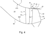
- FIG. 4 shows a sectional view of a structural assembly that defines a flow path 25 and comprises an inlet stator 5, a rotor 6 and flow path boundaries.
- the flow path 25 directs the core air flow A according to FIG Figure 1 through the core engine.
- the flow path 25 is delimited radially on the inside by inner wall or hub structures 95 which form an inner flow path boundary 950.
- the flow path 25 is delimited radially on the outside by a compressor housing 4 that forms a radially outer flow path boundary 410.
- the structural assembly is located in the area of the first stage of a compressor.
- the compressor comprises the inlet stator 5, which has stator blades 50 which can be adjusted in terms of the stagger angle. The swirl in the flow is increased by the inlet guide wheel 5 and, as a result, the following rotor 6 is flown against in a more effective manner.
- the rotor 6 comprises a series of rotor blades or rotor blades 60, which extend radially in the flow path 25.
- the rotor blades 60 have a leading edge 61, a trailing edge 62 and a blade tip 63.
- a gap is implemented between the blade tip 63 and the compressor housing 4.
- an inlet lining 7 is integrated into the compressor housing 4.
- the housing wall of the compressor housing 4 facing the flow path 25 forms a corresponding recess 45 for this purpose.
- the inlet coating 7 forms the flow path boundary 410.
- the running-in lining 7 is fastened in the recess 45 on its radially outer side.
- a housing structure 8 is integrated into the run-in coating 7. In the illustrated embodiment, this is implemented by axial grooves 81 in the shape of a half-heart.
- a such axial groove 81 in half-heart shape 81 is in the Figure 4 shown schematically. However, the illustration should not be understood to mean that the housing structure 8 would protrude from the run-in coating 7 in the radial direction. The illustration only serves to show the axial course of the axial groove 81 in half-heart shape.
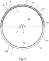
- FIG. 5 shows a sectional view through a compressor housing 4 and a run-in lining 7 in a plane perpendicular to the axial direction which is defined by the machine axis 9 (along the line DD of FIG Figure 4 ).
- the direction of rotation of the rotor 6 is marked with u.
- the compressor housing 4 has an upper compressor housing 410 and a lower compressor housing 420.
- the upper compressor housing 410 and the lower compressor housing 420 indicate spatial areas of the compressor housing 4. These are separated from one another by the horizontal plane 100.
- the upper compressor housing 410 and the lower compressor housing 420 can in principle be formed by any desired structures.
- the compressor housing comprises an upper circumferential segment 41 and a lower circumferential segment 42.
- the circumferential segments 41, 42 adjoin the flow path 25.
- the upper circumferential segment 41 extends, but not necessarily, in the area of the upper compressor housing 410.
- the lower circumferential segment 42 extends in the area of the lower compressor housing 420.
- the circumferential segments 41, 42 differ in any case in that only one of the circumferential segments forms a housing structure. It is provided that only the upper peripheral segment 41 has a housing structure 8, while the lower peripheral segment 42 has no housing structure.
- the structure of the housing is formed in the illustrated embodiment, but not necessarily in the run-in coating.
- the housing 4 has an upper run-in coating 71, in which a housing structuring 8 is implemented, and a lower run-in coating 72, which is implemented without a housing structuring.
- the two run-in linings 71, 72 extend in the example not according to the invention in FIG Figure 5 in the circumferential direction in each case over 180 ° and adjoin one another in the horizontal plane 100.
- the housing 4 is a divided housing which has two housing halves 411, 421, the dividing plane (ie the horizontal plane 100) between the two housing halves 411, 421 also representing the boundary between the two circumferential segments 41, 42 or run-in coatings 71, 72. one or only some of the circumferential segments have a running-in coating.
- the upper run-in coating 71, in which a casing structure 8 is implemented, and the lower run-in coating 72, which is implemented without a casing structure, consist, according to one embodiment, of the material Metco 601NS, Metco 320NS or Metco 314NS from Oerlikon Metco Switzerland in 8808 Pfäffikon, Switzerland .
- Metco 601NS is a mixture of silicon-aluminum powders and polyester powders.
- Metco 320NS is an aluminum-silicon boron nitride powder.
- Metco 314NS is a thermal spray powder made from a mixture of nickel chromium aluminum bentonite.
- high-temperature plastics, porous materials or metallic honeycomb structures are used as the material for the run-in linings 71, 72.
- the radial thickness of the upper run-in coating 71 and the radial thickness of the lower run-in coating 72 are identical in any case in exemplary embodiments of the invention.
- the run-in linings 71, 72 are part of the compressor housing 4.
- the peripheral segments 41, 42 which are only partially provided with a housing structure, are in FIG Figure 5 formed by the inlet linings 71, 72 or at least include these inlet linings 71, 72.
- the circumferential segments 41, 42 are formed by the actual compressor housing, ie the wall of the compressor housing facing the flow path 25.
- the corresponding structures such as axial grooves are formed directly in the housing wall.
- the axial grooves 81 are also shown in a sectional view in half-heart shape. As explained, the axial course of these axial grooves 81 is in the shape of a half-heart in FIG Figure 4 shown. According to the Figure 5 the axial grooves 81 are slightly inclined with respect to the radial direction. This can be done in one or the other circumferential direction. The axial grooves 81 can also run exactly in the radial direction.
- a run-in coating 72 is only provided in the lower circumferential segment 72.
- the structure of the housing 8 is not implemented in an upper run-in coating, but in an upper circumferential segment 41 that extends through the housing wall of the compressor housing is realized. So that the flow path 25 does not have a change in cross section in such a case, it is provided that the housing 4 has a larger housing radius in the lower compressor housing 420 than in the upper compressor housing 410 along the axial area in which it receives the lower inlet coating 72.
- neither the upper housing half 410 nor the lower housing half 420 has a running-in coating.
- a circumferential segment with a housing structure is formed in the upper half of the housing.
- a circumferential segment is formed without a housing structure.
- the Figure 6 shows a further embodiment of a structural assembly according to the present invention.
- the structural assembly comprises a compressor housing 4 which forms a flow path boundary 410.
- a rotor 6 comprises rotor blades 60, each of which has a leading edge 61, a trailing edge 62 and a blade tip 63. It can be seen that a gap is formed between the blade tip 63 and the flow path boundary 410.
- the machine axis 9 is also shown.
- a housing structure 8 is formed directly in the housing wall of the compressor housing 4 without the use of an inlet coating.
- axial grooves 81 in half-heart shape.
- Such half-heart shaped axial grooves are in the DE 10 2007 056 953 A1 described.
- the axial groove 81 with a half-heart shape can then be further defined by two angles ⁇ , ⁇ . These span the starting area and the end area of the cross-sectional curve given by the half heart shape.
- the angle legs are arranged tangentially to the curve profile at the beginning or at the end.
- the angle ⁇ is, for example, in the range between 20 ° and 70 ° to the wall of the compressor housing and the angle ⁇ is, for example, in the range between 30 ° and 80 ° to the wall of the compressor housing.
- the Figure 6 further shows that, in exemplary embodiments of the invention, the housing structure 8 in the area of the leading edge 61 of the rotor blades 60 of the rotor 6 is formed.
- the axial extent of the axial grooves 81 is selected in such a way that the axial grooves 81 extend from the leading edge 630 of the blade tip 63 by a certain extension length opposite to the axial direction and starting from the leading edge 630 by a certain extension length in the axial direction.
- the extension length in the two directions mentioned is, for example, a maximum of 50% of the axial length of the blade tip 63.
- Such an axial extension of the housing structuring can also be provided in the case of housing structurings designed in a different way.
Landscapes
- Engineering & Computer Science (AREA)
- Mechanical Engineering (AREA)
- General Engineering & Computer Science (AREA)
- Structures Of Non-Positive Displacement Pumps (AREA)
Claims (12)
- Module structural pour un compresseur d'une turbomachine, qui comprend :- un rotor (6) muni d'une pluralité d'aubes (60), qui s'étendent radialement dans un chemin d'écoulement (25) de la turbomachine, et- un boîtier de compresseur (4), qui forme une bordure de chemin d'écoulement (410), qui délimite radialement vers l'extérieur le chemin d'écoulement (25) au travers de la turbomachine,- le boîtier de compresseur (4) comprenant une structuration de boîtier (8) adjacente au rotor (6), qui contre un décrochage tournant,- le boîtier de compresseur (4) comprenant une pluralité de segments périphériques (41, 42), qui s'étendent dans la direction périphérique, uniquement un ou uniquement certains des segments périphériques (41) formant la structuration de boîtier (8), et- au moins un segment périphérique (41, 42) du boîtier de compresseur (4) comprenant une garniture de rodage (7, 71, 72),caractérisé en ce que
uniquement un ou uniquement certains des segments périphériques (41) comprennent une garniture de rodage (71), les segments périphériques (41, 42) présentant deux rayons de boîtier différents, le rayon de boîtier d'un segment périphérique qui comprend une garniture de rodage (7, 71, 72) étant supérieur au rayon de boîtier d'un segment périphérique qui ne comprend pas de garniture de rodage. - Module structural selon la revendication 1, caractérisé en ce que le boîtier de compresseur (4) comprend une moitié de boîtier supérieure (410) et une moitié de boîtier inférieure (420), qui s'étendent chacune dans la direction périphérique sur une zone périphérique de 180°, et en ce que le segment périphérique (41) ou les segments périphériques qui forment la structuration de boîtier (8) sont formés dans la moitié de boîtier supérieure (410) du boîtier de compresseur (4).
- Module structural selon la revendication 2, caractérisé en ce que le boîtier de compresseur (4) comprend exactement deux segments périphériques (41, 42), un segment périphérique supérieur (41) étant formé dans la moitié de boîtier supérieure et un segment périphérique inférieur (42) étant formé dans la moitié de boîtier inférieure, et la structuration de boîtier (8) étant formée dans le segment périphérique supérieur (41) .
- Module structural selon l'une quelconque des revendications précédentes, caractérisé en ce que les segments périphériques (41, 42) présentent le même angle d'extension dans la direction périphérique.
- Module structural selon l'une quelconque des revendications précédentes, caractérisé en ce que la succession des segments périphériques (41, 42) est asymétrique en périphérie dans la direction périphérique.
- Module structural selon l'une quelconque des revendications précédentes, caractérisé en ce qu'au moins un segment périphérique (41), qui comprend la structuration de boîtier (8), comprend une garniture de rodage (71), la structuration de boîtier (8) étant formée dans la garniture de rodage (71).
- Module structural selon la revendication 3, caractérisé en ce qu'uniquement le segment périphérique supérieur (41) ou uniquement le segment périphérique inférieur (42) comprend une garniture de rodage et les deux segments périphériques (41, 42) présentent un rayon de boîtier différent.
- Module structural selon l'une quelconque des revendications précédentes, caractérisé en ce que le boîtier de compresseur (4) est formé par un boîtier divisé en deux, qui comprend deux parties (411, 421), qui s'étendent chacune sur 180° dans la direction périphérique.
- Module structural selon l'une quelconque des revendications précédentes, caractérisé en ce que la structuration de boîtier (8) est configurée sous forme discrète en périphérie.
- Module structural selon l'une quelconque des revendications précédentes, caractérisé en ce que la structuration de boîtier (8) est configurée sous la forme de rainures axiales en demi-cœur (81).
- Module structural selon l'une quelconque des revendications précédentes, caractérisé en ce que la structuration de boîtier (8) est configurée adjacente au bord avant des aubes mobiles dans le boîtier de compresseur (4).
- Module structural selon l'une quelconque des revendications précédentes, caractérisé en ce que le rotor (6) est configuré selon une construction BLISK.
Applications Claiming Priority (1)
| Application Number | Priority Date | Filing Date | Title |
|---|---|---|---|
| DE102018116062.3A DE102018116062A1 (de) | 2018-07-03 | 2018-07-03 | Strukturbaugruppe für einen Verdichter einer Strömungsmaschine |
Publications (2)
| Publication Number | Publication Date |
|---|---|
| EP3591237A1 EP3591237A1 (fr) | 2020-01-08 |
| EP3591237B1 true EP3591237B1 (fr) | 2021-05-19 |
Family
ID=67001586
Family Applications (1)
| Application Number | Title | Priority Date | Filing Date |
|---|---|---|---|
| EP19181591.9A Active EP3591237B1 (fr) | 2018-07-03 | 2019-06-21 | Module structural pour un compresseur d'une turbomachine |
Country Status (3)
| Country | Link |
|---|---|
| US (1) | US11131322B2 (fr) |
| EP (1) | EP3591237B1 (fr) |
| DE (1) | DE102018116062A1 (fr) |
Families Citing this family (13)
| Publication number | Priority date | Publication date | Assignee | Title |
|---|---|---|---|---|
| FR3107917B1 (fr) * | 2020-03-04 | 2022-09-09 | Safran | Carter de roue mobile pour turbomachine |
| US12018621B1 (en) | 2023-08-16 | 2024-06-25 | Rolls-Royce North American Technologies Inc. | Adjustable depth tip treatment with rotatable ring with pockets for a fan of a gas turbine engine |
| US12078070B1 (en) | 2023-08-16 | 2024-09-03 | Rolls-Royce North American Technologies Inc. | Adjustable air flow plenum with sliding doors for a fan of a gas turbine engine |
| US12066035B1 (en) | 2023-08-16 | 2024-08-20 | Rolls-Royce North American Technologies Inc. | Adjustable depth tip treatment with axial member with pockets for a fan of a gas turbine engine |
| US11970985B1 (en) | 2023-08-16 | 2024-04-30 | Rolls-Royce North American Technologies Inc. | Adjustable air flow plenum with pivoting vanes for a fan of a gas turbine engine |
| US12085021B1 (en) | 2023-08-16 | 2024-09-10 | Rolls-Royce North American Technologies Inc. | Adjustable air flow plenum with movable closure for a fan of a gas turbine engine |
| US11965528B1 (en) | 2023-08-16 | 2024-04-23 | Rolls-Royce North American Technologies Inc. | Adjustable air flow plenum with circumferential movable closure for a fan of a gas turbine engine |
| US12258870B1 (en) | 2024-03-08 | 2025-03-25 | Rolls-Royce North American Technologies Inc. | Adjustable fan track liner with slotted array active fan tip treatment for distortion tolerance |
| US12286936B1 (en) | 2024-05-09 | 2025-04-29 | Rolls-Royce North American Technologies Inc. | Adjustable fan track liner with groove array active fan tip treatment for distortion tolerance |
| US12209541B1 (en) | 2024-05-09 | 2025-01-28 | Rolls-Royce North American Technologies Inc. | Adjustable fan track liner with dual slotted array active fan tip treatment for distortion tolerance |
| US12215712B1 (en) | 2024-05-09 | 2025-02-04 | Rolls-Royce North American Technologies Inc. | Adjustable fan track liner with dual grooved array active fan tip treatment for distortion tolerance |
| US12168983B1 (en) | 2024-06-28 | 2024-12-17 | Rolls-Royce North American Technologies Inc. | Active fan tip treatment using rotating drum array in fan track liner with axial and circumferential channels for distortion tolerance |
| US12209502B1 (en) | 2024-06-28 | 2025-01-28 | Rolls-Royce North American Technologies Inc. | Active fan tip treatment using rotating drum array with axial channels in fan track liner for distortion tolerance |
Family Cites Families (25)
| Publication number | Priority date | Publication date | Assignee | Title |
|---|---|---|---|---|
| US3890060A (en) * | 1974-02-15 | 1975-06-17 | Gen Electric | Acoustic duct with asymmetric acoustical treatment |
| JP3872966B2 (ja) * | 2001-06-29 | 2007-01-24 | 株式会社日立プラントテクノロジー | 軸流形流体機械 |
| GB2385378B (en) * | 2002-02-14 | 2005-08-31 | Rolls Royce Plc | Engine casing |
| DE102006048933A1 (de) * | 2006-10-17 | 2008-04-24 | Mtu Aero Engines Gmbh | Anordnung zur Strömungsbeeinflussung |
| FR2912789B1 (fr) * | 2007-02-21 | 2009-10-02 | Snecma Sa | Carter avec traitement de carter, compresseur et turbomachine comportant un tel carter. |
| DE102007037924A1 (de) * | 2007-08-10 | 2009-02-12 | Rolls-Royce Deutschland Ltd & Co Kg | Strömungsarbeitsmaschine mit Ringkanalwandausnehmung |
| CN201152282Y (zh) * | 2007-09-26 | 2008-11-19 | 北京航空航天大学 | 一种非轴对称叶尖激励发生器 |
| DE102007053135A1 (de) * | 2007-11-08 | 2009-05-14 | Mtu Aero Engines Gmbh | Gasturbinenbauteil, insbesondere Flugtriebwerksbauteil bzw. Verdichterbauteil |
| CN201190695Y (zh) | 2007-11-09 | 2009-02-04 | 北京航空航天大学 | 一种非轴对称组合处理机匣 |
| DE102007056953B4 (de) | 2007-11-27 | 2015-10-22 | Rolls-Royce Deutschland Ltd & Co Kg | Strömungsarbeitsmaschine mit Ringkanalwandausnehmung |
| DE102008010283A1 (de) * | 2008-02-21 | 2009-08-27 | Mtu Aero Engines Gmbh | Zirkulationsstruktur für einen Turboverdichter |
| FR2930590B1 (fr) * | 2008-04-23 | 2013-05-31 | Snecma | Carter de turbomachine comportant un dispositif empechant une instabilite lors d'un contact entre le carter et le rotor |
| DE102008037154A1 (de) | 2008-08-08 | 2010-02-11 | Rolls-Royce Deutschland Ltd & Co Kg | Strömungsarbeitsmaschine |
| GB2477745A (en) * | 2010-02-11 | 2011-08-17 | Rolls Royce Plc | Compressor Casing |
| JP4841680B2 (ja) * | 2010-05-10 | 2011-12-21 | 川崎重工業株式会社 | ガスタービン圧縮機の抽気構造 |
| DE102010036071A1 (de) * | 2010-09-01 | 2012-03-01 | Mtu Aero Engines Gmbh | Gehäuseseitige Struktur einer Turbomaschine |
| DE102011007767A1 (de) * | 2011-04-20 | 2012-10-25 | Rolls-Royce Deutschland Ltd & Co Kg | Strömungsmaschine |
| FR2975735A1 (fr) * | 2011-05-27 | 2012-11-30 | Snecma | Carter de soufflante de turbomachine et procede pour sa fabrication |
| GB201219617D0 (en) * | 2012-11-01 | 2012-12-12 | Rolls Royce Deutschland & Co Kg | Bleed flow passage |
| JP6109548B2 (ja) * | 2012-11-30 | 2017-04-05 | 三菱重工業株式会社 | 圧縮機 |
| DE102013210171A1 (de) * | 2013-05-31 | 2014-12-04 | Rolls-Royce Deutschland Ltd & Co Kg | Strukturbaugruppe für eine Strömungsmaschine |
| DE102013210169A1 (de) * | 2013-05-31 | 2014-12-04 | Rolls-Royce Deutschland Ltd & Co Kg | Strukturbaugruppe für eine Strömungsmaschine |
| US10047620B2 (en) * | 2014-12-16 | 2018-08-14 | General Electric Company | Circumferentially varying axial compressor endwall treatment for controlling leakage flow therein |
| GB201514896D0 (en) * | 2015-08-21 | 2015-10-07 | Rolls Royce Plc | Rotor tip clearance |
| US10472985B2 (en) * | 2016-12-12 | 2019-11-12 | Honeywell International Inc. | Engine case for fan blade out retention |
-
2018
- 2018-07-03 DE DE102018116062.3A patent/DE102018116062A1/de not_active Withdrawn
-
2019
- 2019-06-21 EP EP19181591.9A patent/EP3591237B1/fr active Active
- 2019-06-26 US US16/453,193 patent/US11131322B2/en active Active
Also Published As
| Publication number | Publication date |
|---|---|
| EP3591237A1 (fr) | 2020-01-08 |
| US20200011346A1 (en) | 2020-01-09 |
| DE102018116062A1 (de) | 2020-01-09 |
| US11131322B2 (en) | 2021-09-28 |
Similar Documents
| Publication | Publication Date | Title |
|---|---|---|
| EP3591237B1 (fr) | Module structural pour un compresseur d'une turbomachine | |
| EP3940200B1 (fr) | Roue à aubes d'une turbomachine | |
| EP3715586B1 (fr) | Pale d'aube de rotor d'une turbomachine | |
| DE102020103776A1 (de) | Getriebe-Gasturbinentriebwerk | |
| DE102018107494A1 (de) | Planetengetriebevorrichtung mit einer Ölversorgungseinrichtung, Gasturbinentriebwerk mit einer Planetengetriebevorrichtung und Verfahren zum Herstellen einer Schaufelpumpe | |
| DE102020103780A1 (de) | Getriebe-Gasturbinentriebwerk | |
| DE102018113753A1 (de) | Planetengetriebe und Gasturbinentriebwerk | |
| WO2020260255A1 (fr) | Transmission et groupe motopropulseur à turbine à gaz | |
| DE102019106633A1 (de) | Getriebe und Gasturbinentriebwerk | |
| DE102020215576A1 (de) | Strömungsleitvorrichtung und ein Gasturbinentriebwerk | |
| EP3599349A1 (fr) | Module structural avec aubes à calage variable inclinées pour un compresseur d'une turbomachine | |
| DE102020113053A1 (de) | Gasturbinentriebwerk | |
| DE102018106864A1 (de) | Verfahren zum Zusammenbau eines Planetengetriebes, ein Planetenträger und ein Flugzeugtriebwerk | |
| EP3543481B1 (fr) | Turbomoteur à gaz et procédé d'introduction de l'huile dans un agencement de transmission | |
| EP4034756B1 (fr) | Turbine à gaz d'aéronef comprenant une transmission | |
| DE102018119463B4 (de) | Labyrinthdichtungssystem und Gasturbinentriebwerk mit einem Labyrinthdichtungssystem | |
| DE102021115337A1 (de) | Planetengetriebe eines Gasturbinetriebwerkes | |
| DE102021209552A1 (de) | Planetengetriebe | |
| DE102020132953A1 (de) | Fan eines Gasturbinentriebwerks | |
| DE102020122721A1 (de) | Getriebeteil | |
| DE102020122418A1 (de) | Planetengetriebe | |
| WO2021069186A1 (fr) | Engrenage à manchon en céramique | |
| DE102020116522A1 (de) | Planetengetriebe | |
| DE102020116785B4 (de) | Strukturbaugruppe für ein Gasturbinentriebwerk | |
| DE102019126144A1 (de) | Gasturbinentriebwerk und Verfahren zur Einstellung eines Ausgangsleitrads im Nebenstromkanal eines Gasturbinentriebwerks |
Legal Events
| Date | Code | Title | Description |
|---|---|---|---|
| PUAI | Public reference made under article 153(3) epc to a published international application that has entered the european phase |
Free format text: ORIGINAL CODE: 0009012 |
|
| STAA | Information on the status of an ep patent application or granted ep patent |
Free format text: STATUS: THE APPLICATION HAS BEEN PUBLISHED |
|
| AK | Designated contracting states |
Kind code of ref document: A1 Designated state(s): AL AT BE BG CH CY CZ DE DK EE ES FI FR GB GR HR HU IE IS IT LI LT LU LV MC MK MT NL NO PL PT RO RS SE SI SK SM TR |
|
| AX | Request for extension of the european patent |
Extension state: BA ME |
|
| RAP1 | Party data changed (applicant data changed or rights of an application transferred) |
Owner name: ROLLS-ROYCE DEUTSCHLAND LTD & CO KG |
|
| STAA | Information on the status of an ep patent application or granted ep patent |
Free format text: STATUS: REQUEST FOR EXAMINATION WAS MADE |
|
| 17P | Request for examination filed |
Effective date: 20200707 |
|
| RBV | Designated contracting states (corrected) |
Designated state(s): AL AT BE BG CH CY CZ DE DK EE ES FI FR GB GR HR HU IE IS IT LI LT LU LV MC MK MT NL NO PL PT RO RS SE SI SK SM TR |
|
| GRAP | Despatch of communication of intention to grant a patent |
Free format text: ORIGINAL CODE: EPIDOSNIGR1 |
|
| STAA | Information on the status of an ep patent application or granted ep patent |
Free format text: STATUS: GRANT OF PATENT IS INTENDED |
|
| INTG | Intention to grant announced |
Effective date: 20201218 |
|
| GRAS | Grant fee paid |
Free format text: ORIGINAL CODE: EPIDOSNIGR3 |
|
| GRAA | (expected) grant |
Free format text: ORIGINAL CODE: 0009210 |
|
| STAA | Information on the status of an ep patent application or granted ep patent |
Free format text: STATUS: THE PATENT HAS BEEN GRANTED |
|
| AK | Designated contracting states |
Kind code of ref document: B1 Designated state(s): AL AT BE BG CH CY CZ DE DK EE ES FI FR GB GR HR HU IE IS IT LI LT LU LV MC MK MT NL NO PL PT RO RS SE SI SK SM TR |
|
| REG | Reference to a national code |
Ref country code: GB Ref legal event code: FG4D Free format text: NOT ENGLISH |
|
| RIN1 | Information on inventor provided before grant (corrected) |
Inventor name: BECKER, BERND Inventor name: GIERSCH, THOMAS Inventor name: GROTHE, PATRICK Inventor name: HEINICHEN, FRANK Inventor name: JUENGST, MAXIMILIAN |
|
| REG | Reference to a national code |
Ref country code: CH Ref legal event code: EP |
|
| REG | Reference to a national code |
Ref country code: DE Ref legal event code: R096 Ref document number: 502019001443 Country of ref document: DE |
|
| REG | Reference to a national code |
Ref country code: AT Ref legal event code: REF Ref document number: 1394246 Country of ref document: AT Kind code of ref document: T Effective date: 20210615 |
|
| REG | Reference to a national code |
Ref country code: IE Ref legal event code: FG4D Free format text: LANGUAGE OF EP DOCUMENT: GERMAN |
|
| REG | Reference to a national code |
Ref country code: LT Ref legal event code: MG9D |
|
| REG | Reference to a national code |
Ref country code: NL Ref legal event code: MP Effective date: 20210519 |
|
| PG25 | Lapsed in a contracting state [announced via postgrant information from national office to epo] |
Ref country code: BG Free format text: LAPSE BECAUSE OF FAILURE TO SUBMIT A TRANSLATION OF THE DESCRIPTION OR TO PAY THE FEE WITHIN THE PRESCRIBED TIME-LIMIT Effective date: 20210819 Ref country code: LT Free format text: LAPSE BECAUSE OF FAILURE TO SUBMIT A TRANSLATION OF THE DESCRIPTION OR TO PAY THE FEE WITHIN THE PRESCRIBED TIME-LIMIT Effective date: 20210519 Ref country code: HR Free format text: LAPSE BECAUSE OF FAILURE TO SUBMIT A TRANSLATION OF THE DESCRIPTION OR TO PAY THE FEE WITHIN THE PRESCRIBED TIME-LIMIT Effective date: 20210519 Ref country code: FI Free format text: LAPSE BECAUSE OF FAILURE TO SUBMIT A TRANSLATION OF THE DESCRIPTION OR TO PAY THE FEE WITHIN THE PRESCRIBED TIME-LIMIT Effective date: 20210519 |
|
| PG25 | Lapsed in a contracting state [announced via postgrant information from national office to epo] |
Ref country code: GR Free format text: LAPSE BECAUSE OF FAILURE TO SUBMIT A TRANSLATION OF THE DESCRIPTION OR TO PAY THE FEE WITHIN THE PRESCRIBED TIME-LIMIT Effective date: 20210820 Ref country code: IS Free format text: LAPSE BECAUSE OF FAILURE TO SUBMIT A TRANSLATION OF THE DESCRIPTION OR TO PAY THE FEE WITHIN THE PRESCRIBED TIME-LIMIT Effective date: 20210919 Ref country code: RS Free format text: LAPSE BECAUSE OF FAILURE TO SUBMIT A TRANSLATION OF THE DESCRIPTION OR TO PAY THE FEE WITHIN THE PRESCRIBED TIME-LIMIT Effective date: 20210519 Ref country code: SE Free format text: LAPSE BECAUSE OF FAILURE TO SUBMIT A TRANSLATION OF THE DESCRIPTION OR TO PAY THE FEE WITHIN THE PRESCRIBED TIME-LIMIT Effective date: 20210519 Ref country code: PT Free format text: LAPSE BECAUSE OF FAILURE TO SUBMIT A TRANSLATION OF THE DESCRIPTION OR TO PAY THE FEE WITHIN THE PRESCRIBED TIME-LIMIT Effective date: 20210920 Ref country code: PL Free format text: LAPSE BECAUSE OF FAILURE TO SUBMIT A TRANSLATION OF THE DESCRIPTION OR TO PAY THE FEE WITHIN THE PRESCRIBED TIME-LIMIT Effective date: 20210519 Ref country code: NO Free format text: LAPSE BECAUSE OF FAILURE TO SUBMIT A TRANSLATION OF THE DESCRIPTION OR TO PAY THE FEE WITHIN THE PRESCRIBED TIME-LIMIT Effective date: 20210819 Ref country code: LV Free format text: LAPSE BECAUSE OF FAILURE TO SUBMIT A TRANSLATION OF THE DESCRIPTION OR TO PAY THE FEE WITHIN THE PRESCRIBED TIME-LIMIT Effective date: 20210519 |
|
| PG25 | Lapsed in a contracting state [announced via postgrant information from national office to epo] |
Ref country code: NL Free format text: LAPSE BECAUSE OF FAILURE TO SUBMIT A TRANSLATION OF THE DESCRIPTION OR TO PAY THE FEE WITHIN THE PRESCRIBED TIME-LIMIT Effective date: 20210519 |
|
| PG25 | Lapsed in a contracting state [announced via postgrant information from national office to epo] |
Ref country code: RO Free format text: LAPSE BECAUSE OF FAILURE TO SUBMIT A TRANSLATION OF THE DESCRIPTION OR TO PAY THE FEE WITHIN THE PRESCRIBED TIME-LIMIT Effective date: 20210519 Ref country code: SM Free format text: LAPSE BECAUSE OF FAILURE TO SUBMIT A TRANSLATION OF THE DESCRIPTION OR TO PAY THE FEE WITHIN THE PRESCRIBED TIME-LIMIT Effective date: 20210519 Ref country code: CZ Free format text: LAPSE BECAUSE OF FAILURE TO SUBMIT A TRANSLATION OF THE DESCRIPTION OR TO PAY THE FEE WITHIN THE PRESCRIBED TIME-LIMIT Effective date: 20210519 Ref country code: DK Free format text: LAPSE BECAUSE OF FAILURE TO SUBMIT A TRANSLATION OF THE DESCRIPTION OR TO PAY THE FEE WITHIN THE PRESCRIBED TIME-LIMIT Effective date: 20210519 Ref country code: ES Free format text: LAPSE BECAUSE OF FAILURE TO SUBMIT A TRANSLATION OF THE DESCRIPTION OR TO PAY THE FEE WITHIN THE PRESCRIBED TIME-LIMIT Effective date: 20210519 Ref country code: EE Free format text: LAPSE BECAUSE OF FAILURE TO SUBMIT A TRANSLATION OF THE DESCRIPTION OR TO PAY THE FEE WITHIN THE PRESCRIBED TIME-LIMIT Effective date: 20210519 Ref country code: SK Free format text: LAPSE BECAUSE OF FAILURE TO SUBMIT A TRANSLATION OF THE DESCRIPTION OR TO PAY THE FEE WITHIN THE PRESCRIBED TIME-LIMIT Effective date: 20210519 |
|
| REG | Reference to a national code |
Ref country code: DE Ref legal event code: R097 Ref document number: 502019001443 Country of ref document: DE |
|
| REG | Reference to a national code |
Ref country code: BE Ref legal event code: MM Effective date: 20210630 |
|
| PLBE | No opposition filed within time limit |
Free format text: ORIGINAL CODE: 0009261 |
|
| STAA | Information on the status of an ep patent application or granted ep patent |
Free format text: STATUS: NO OPPOSITION FILED WITHIN TIME LIMIT |
|
| PG25 | Lapsed in a contracting state [announced via postgrant information from national office to epo] |
Ref country code: MC Free format text: LAPSE BECAUSE OF FAILURE TO SUBMIT A TRANSLATION OF THE DESCRIPTION OR TO PAY THE FEE WITHIN THE PRESCRIBED TIME-LIMIT Effective date: 20210519 Ref country code: LU Free format text: LAPSE BECAUSE OF NON-PAYMENT OF DUE FEES Effective date: 20210621 |
|
| 26N | No opposition filed |
Effective date: 20220222 |
|
| PG25 | Lapsed in a contracting state [announced via postgrant information from national office to epo] |
Ref country code: IE Free format text: LAPSE BECAUSE OF NON-PAYMENT OF DUE FEES Effective date: 20210621 |
|
| PG25 | Lapsed in a contracting state [announced via postgrant information from national office to epo] |
Ref country code: IS Free format text: LAPSE BECAUSE OF FAILURE TO SUBMIT A TRANSLATION OF THE DESCRIPTION OR TO PAY THE FEE WITHIN THE PRESCRIBED TIME-LIMIT Effective date: 20210919 Ref country code: AL Free format text: LAPSE BECAUSE OF FAILURE TO SUBMIT A TRANSLATION OF THE DESCRIPTION OR TO PAY THE FEE WITHIN THE PRESCRIBED TIME-LIMIT Effective date: 20210519 |
|
| PG25 | Lapsed in a contracting state [announced via postgrant information from national office to epo] |
Ref country code: IT Free format text: LAPSE BECAUSE OF FAILURE TO SUBMIT A TRANSLATION OF THE DESCRIPTION OR TO PAY THE FEE WITHIN THE PRESCRIBED TIME-LIMIT Effective date: 20210519 Ref country code: BE Free format text: LAPSE BECAUSE OF NON-PAYMENT OF DUE FEES Effective date: 20210630 |
|
| REG | Reference to a national code |
Ref country code: CH Ref legal event code: PL |
|
| PG25 | Lapsed in a contracting state [announced via postgrant information from national office to epo] |
Ref country code: LI Free format text: LAPSE BECAUSE OF NON-PAYMENT OF DUE FEES Effective date: 20220630 Ref country code: CH Free format text: LAPSE BECAUSE OF NON-PAYMENT OF DUE FEES Effective date: 20220630 |
|
| PG25 | Lapsed in a contracting state [announced via postgrant information from national office to epo] |
Ref country code: CY Free format text: LAPSE BECAUSE OF FAILURE TO SUBMIT A TRANSLATION OF THE DESCRIPTION OR TO PAY THE FEE WITHIN THE PRESCRIBED TIME-LIMIT Effective date: 20210519 |
|
| PG25 | Lapsed in a contracting state [announced via postgrant information from national office to epo] |
Ref country code: HU Free format text: LAPSE BECAUSE OF FAILURE TO SUBMIT A TRANSLATION OF THE DESCRIPTION OR TO PAY THE FEE WITHIN THE PRESCRIBED TIME-LIMIT; INVALID AB INITIO Effective date: 20190621 |
|
| GBPC | Gb: european patent ceased through non-payment of renewal fee |
Effective date: 20230621 |
|
| PG25 | Lapsed in a contracting state [announced via postgrant information from national office to epo] |
Ref country code: MK Free format text: LAPSE BECAUSE OF FAILURE TO SUBMIT A TRANSLATION OF THE DESCRIPTION OR TO PAY THE FEE WITHIN THE PRESCRIBED TIME-LIMIT Effective date: 20210519 Ref country code: GB Free format text: LAPSE BECAUSE OF NON-PAYMENT OF DUE FEES Effective date: 20230621 |
|
| PG25 | Lapsed in a contracting state [announced via postgrant information from national office to epo] |
Ref country code: MT Free format text: LAPSE BECAUSE OF FAILURE TO SUBMIT A TRANSLATION OF THE DESCRIPTION OR TO PAY THE FEE WITHIN THE PRESCRIBED TIME-LIMIT Effective date: 20210519 |
|
| PGFP | Annual fee paid to national office [announced via postgrant information from national office to epo] |
Ref country code: DE Payment date: 20250626 Year of fee payment: 7 |
|
| PGFP | Annual fee paid to national office [announced via postgrant information from national office to epo] |
Ref country code: FR Payment date: 20250624 Year of fee payment: 7 |
|
| REG | Reference to a national code |
Ref country code: AT Ref legal event code: MM01 Ref document number: 1394246 Country of ref document: AT Kind code of ref document: T Effective date: 20240621 |
|
| PG25 | Lapsed in a contracting state [announced via postgrant information from national office to epo] |
Ref country code: AT Free format text: LAPSE BECAUSE OF NON-PAYMENT OF DUE FEES Effective date: 20240621 |
|
| PG25 | Lapsed in a contracting state [announced via postgrant information from national office to epo] |
Ref country code: TR Free format text: LAPSE BECAUSE OF FAILURE TO SUBMIT A TRANSLATION OF THE DESCRIPTION OR TO PAY THE FEE WITHIN THE PRESCRIBED TIME-LIMIT Effective date: 20210519 |
|
| PGFP | Annual fee paid to national office [announced via postgrant information from national office to epo] |
Ref country code: AT Payment date: 20260410 Year of fee payment: 5 |