EP3590555B1 - Appareil de thérapie à conducteurs de fluide intégrés et atténuation de bruit - Google Patents
Appareil de thérapie à conducteurs de fluide intégrés et atténuation de bruit Download PDFInfo
- Publication number
- EP3590555B1 EP3590555B1 EP19193338.1A EP19193338A EP3590555B1 EP 3590555 B1 EP3590555 B1 EP 3590555B1 EP 19193338 A EP19193338 A EP 19193338A EP 3590555 B1 EP3590555 B1 EP 3590555B1
- Authority
- EP
- European Patent Office
- Prior art keywords
- housing
- fluid
- port
- channel
- pressure
- Prior art date
- Legal status (The legal status is an assumption and is not a legal conclusion. Google has not performed a legal analysis and makes no representation as to the accuracy of the status listed.)
- Active
Links
- 239000012530 fluid Substances 0.000 title claims description 138
- 238000002560 therapeutic procedure Methods 0.000 title claims description 27
- 239000004020 conductor Substances 0.000 title description 13
- 239000000853 adhesive Substances 0.000 claims description 7
- 230000001070 adhesive effect Effects 0.000 claims description 7
- 238000011144 upstream manufacturing Methods 0.000 claims description 3
- 210000001519 tissue Anatomy 0.000 description 69
- 239000006260 foam Substances 0.000 description 18
- 206010052428 Wound Diseases 0.000 description 12
- 208000027418 Wounds and injury Diseases 0.000 description 12
- 239000000463 material Substances 0.000 description 11
- 230000001225 therapeutic effect Effects 0.000 description 9
- 230000008901 benefit Effects 0.000 description 5
- 238000000034 method Methods 0.000 description 5
- 238000005192 partition Methods 0.000 description 5
- 230000010261 cell growth Effects 0.000 description 4
- 238000004519 manufacturing process Methods 0.000 description 4
- 230000037361 pathway Effects 0.000 description 4
- 229920000954 Polyglycolide Polymers 0.000 description 3
- 230000008878 coupling Effects 0.000 description 3
- 238000010168 coupling process Methods 0.000 description 3
- 238000005859 coupling reaction Methods 0.000 description 3
- 210000000416 exudates and transudate Anatomy 0.000 description 3
- 238000001746 injection moulding Methods 0.000 description 3
- 239000007788 liquid Substances 0.000 description 3
- 239000004633 polyglycolic acid Substances 0.000 description 3
- 239000011148 porous material Substances 0.000 description 3
- 230000008569 process Effects 0.000 description 3
- 239000000126 substance Substances 0.000 description 3
- 239000004721 Polyphenylene oxide Substances 0.000 description 2
- 208000025865 Ulcer Diseases 0.000 description 2
- 239000003522 acrylic cement Substances 0.000 description 2
- 230000004888 barrier function Effects 0.000 description 2
- 230000007423 decrease Effects 0.000 description 2
- 238000013461 design Methods 0.000 description 2
- 238000011161 development Methods 0.000 description 2
- 238000010586 diagram Methods 0.000 description 2
- 210000002615 epidermis Anatomy 0.000 description 2
- 239000006261 foam material Substances 0.000 description 2
- 239000000499 gel Substances 0.000 description 2
- 230000012010 growth Effects 0.000 description 2
- 230000002209 hydrophobic effect Effects 0.000 description 2
- 208000014674 injury Diseases 0.000 description 2
- 239000000203 mixture Substances 0.000 description 2
- 229920000570 polyether Polymers 0.000 description 2
- 239000004626 polylactic acid Substances 0.000 description 2
- 239000007787 solid Substances 0.000 description 2
- 238000003860 storage Methods 0.000 description 2
- 230000008733 trauma Effects 0.000 description 2
- 231100000397 ulcer Toxicity 0.000 description 2
- 235000014653 Carica parviflora Nutrition 0.000 description 1
- 241000243321 Cnidaria Species 0.000 description 1
- 102000008186 Collagen Human genes 0.000 description 1
- 108010035532 Collagen Proteins 0.000 description 1
- 206010063560 Excessive granulation tissue Diseases 0.000 description 1
- 229920000877 Melamine resin Polymers 0.000 description 1
- 229920005830 Polyurethane Foam Polymers 0.000 description 1
- 239000004372 Polyvinyl alcohol Substances 0.000 description 1
- 239000004820 Pressure-sensitive adhesive Substances 0.000 description 1
- 229920001247 Reticulated foam Polymers 0.000 description 1
- 230000001154 acute effect Effects 0.000 description 1
- 210000000577 adipose tissue Anatomy 0.000 description 1
- 230000002411 adverse Effects 0.000 description 1
- WYTGDNHDOZPMIW-RCBQFDQVSA-N alstonine Natural products C1=CC2=C3C=CC=CC3=NC2=C2N1C[C@H]1[C@H](C)OC=C(C(=O)OC)[C@H]1C2 WYTGDNHDOZPMIW-RCBQFDQVSA-N 0.000 description 1
- 230000001580 bacterial effect Effects 0.000 description 1
- 230000015572 biosynthetic process Effects 0.000 description 1
- 230000017531 blood circulation Effects 0.000 description 1
- 210000000988 bone and bone Anatomy 0.000 description 1
- 229910000389 calcium phosphate Inorganic materials 0.000 description 1
- 239000001506 calcium phosphate Substances 0.000 description 1
- 235000011010 calcium phosphates Nutrition 0.000 description 1
- 150000004649 carbonic acid derivatives Chemical class 0.000 description 1
- 210000000845 cartilage Anatomy 0.000 description 1
- 230000001413 cellular effect Effects 0.000 description 1
- 238000012412 chemical coupling Methods 0.000 description 1
- 230000001684 chronic effect Effects 0.000 description 1
- 239000011248 coating agent Substances 0.000 description 1
- 238000000576 coating method Methods 0.000 description 1
- 229920001436 collagen Polymers 0.000 description 1
- 238000009833 condensation Methods 0.000 description 1
- 230000005494 condensation Effects 0.000 description 1
- 210000002808 connective tissue Anatomy 0.000 description 1
- 230000007547 defect Effects 0.000 description 1
- 230000002950 deficient Effects 0.000 description 1
- 230000001419 dependent effect Effects 0.000 description 1
- 206010012601 diabetes mellitus Diseases 0.000 description 1
- 238000009826 distribution Methods 0.000 description 1
- 230000002500 effect on skin Effects 0.000 description 1
- 230000000694 effects Effects 0.000 description 1
- 210000000981 epithelium Anatomy 0.000 description 1
- 238000005469 granulation Methods 0.000 description 1
- 230000003179 granulation Effects 0.000 description 1
- 210000001126 granulation tissue Anatomy 0.000 description 1
- 230000035876 healing Effects 0.000 description 1
- 239000000416 hydrocolloid Substances 0.000 description 1
- 239000000017 hydrogel Substances 0.000 description 1
- 230000002706 hydrostatic effect Effects 0.000 description 1
- 125000002887 hydroxy group Chemical group [H]O* 0.000 description 1
- 238000003780 insertion Methods 0.000 description 1
- 230000037431 insertion Effects 0.000 description 1
- 230000001788 irregular Effects 0.000 description 1
- 238000002372 labelling Methods 0.000 description 1
- 210000003041 ligament Anatomy 0.000 description 1
- 239000004620 low density foam Substances 0.000 description 1
- 230000007246 mechanism Effects 0.000 description 1
- JDSHMPZPIAZGSV-UHFFFAOYSA-N melamine Chemical compound NC1=NC(N)=NC(N)=N1 JDSHMPZPIAZGSV-UHFFFAOYSA-N 0.000 description 1
- 239000012528 membrane Substances 0.000 description 1
- 230000005012 migration Effects 0.000 description 1
- 238000013508 migration Methods 0.000 description 1
- 238000012986 modification Methods 0.000 description 1
- 230000004048 modification Effects 0.000 description 1
- 238000000465 moulding Methods 0.000 description 1
- 210000003205 muscle Anatomy 0.000 description 1
- 238000009581 negative-pressure wound therapy Methods 0.000 description 1
- 230000001537 neural effect Effects 0.000 description 1
- 206010033675 panniculitis Diseases 0.000 description 1
- 239000006072 paste Substances 0.000 description 1
- 230000002093 peripheral effect Effects 0.000 description 1
- 230000035699 permeability Effects 0.000 description 1
- 229920000747 poly(lactic acid) Polymers 0.000 description 1
- 229920000515 polycarbonate Polymers 0.000 description 1
- 239000004417 polycarbonate Substances 0.000 description 1
- 229920000728 polyester Polymers 0.000 description 1
- 229920006267 polyester film Polymers 0.000 description 1
- 229920000642 polymer Polymers 0.000 description 1
- 229920001296 polysiloxane Polymers 0.000 description 1
- 229920002635 polyurethane Polymers 0.000 description 1
- 239000004814 polyurethane Substances 0.000 description 1
- 229920006264 polyurethane film Polymers 0.000 description 1
- 239000011496 polyurethane foam Substances 0.000 description 1
- 229920002451 polyvinyl alcohol Polymers 0.000 description 1
- 238000012545 processing Methods 0.000 description 1
- 238000007789 sealing Methods 0.000 description 1
- 210000004304 subcutaneous tissue Anatomy 0.000 description 1
- 238000001356 surgical procedure Methods 0.000 description 1
- 210000002435 tendon Anatomy 0.000 description 1
- 229920002725 thermoplastic elastomer Polymers 0.000 description 1
- 230000000472 traumatic effect Effects 0.000 description 1
- QORWJWZARLRLPR-UHFFFAOYSA-H tricalcium bis(phosphate) Chemical compound [Ca+2].[Ca+2].[Ca+2].[O-]P([O-])([O-])=O.[O-]P([O-])([O-])=O QORWJWZARLRLPR-UHFFFAOYSA-H 0.000 description 1
- 230000002792 vascular Effects 0.000 description 1
- 201000002282 venous insufficiency Diseases 0.000 description 1
- 239000002699 waste material Substances 0.000 description 1
- XLYOFNOQVPJJNP-UHFFFAOYSA-N water Chemical compound O XLYOFNOQVPJJNP-UHFFFAOYSA-N 0.000 description 1
Images


Classifications
-
- A—HUMAN NECESSITIES
- A61—MEDICAL OR VETERINARY SCIENCE; HYGIENE
- A61M—DEVICES FOR INTRODUCING MEDIA INTO, OR ONTO, THE BODY; DEVICES FOR TRANSDUCING BODY MEDIA OR FOR TAKING MEDIA FROM THE BODY; DEVICES FOR PRODUCING OR ENDING SLEEP OR STUPOR
- A61M1/00—Suction or pumping devices for medical purposes; Devices for carrying-off, for treatment of, or for carrying-over, body-liquids; Drainage systems
- A61M1/71—Suction drainage systems
- A61M1/72—Cassettes forming partially or totally the fluid circuit
-
- A—HUMAN NECESSITIES
- A61—MEDICAL OR VETERINARY SCIENCE; HYGIENE
- A61M—DEVICES FOR INTRODUCING MEDIA INTO, OR ONTO, THE BODY; DEVICES FOR TRANSDUCING BODY MEDIA OR FOR TAKING MEDIA FROM THE BODY; DEVICES FOR PRODUCING OR ENDING SLEEP OR STUPOR
- A61M1/00—Suction or pumping devices for medical purposes; Devices for carrying-off, for treatment of, or for carrying-over, body-liquids; Drainage systems
- A61M1/90—Negative pressure wound therapy devices, i.e. devices for applying suction to a wound to promote healing, e.g. including a vacuum dressing
- A61M1/96—Suction control thereof
- A61M1/962—Suction control thereof having pumping means on the suction site, e.g. miniature pump on dressing or dressing capable of exerting suction
-
- A—HUMAN NECESSITIES
- A61—MEDICAL OR VETERINARY SCIENCE; HYGIENE
- A61M—DEVICES FOR INTRODUCING MEDIA INTO, OR ONTO, THE BODY; DEVICES FOR TRANSDUCING BODY MEDIA OR FOR TAKING MEDIA FROM THE BODY; DEVICES FOR PRODUCING OR ENDING SLEEP OR STUPOR
- A61M1/00—Suction or pumping devices for medical purposes; Devices for carrying-off, for treatment of, or for carrying-over, body-liquids; Drainage systems
- A61M1/14—Dialysis systems; Artificial kidneys; Blood oxygenators ; Reciprocating systems for treatment of body fluids, e.g. single needle systems for hemofiltration or pheresis
- A61M1/15—Dialysis systems; Artificial kidneys; Blood oxygenators ; Reciprocating systems for treatment of body fluids, e.g. single needle systems for hemofiltration or pheresis with a cassette forming partially or totally the flow circuit for the treating fluid, e.g. the dialysate fluid circuit or the treating gas circuit
-
- A—HUMAN NECESSITIES
- A61—MEDICAL OR VETERINARY SCIENCE; HYGIENE
- A61M—DEVICES FOR INTRODUCING MEDIA INTO, OR ONTO, THE BODY; DEVICES FOR TRANSDUCING BODY MEDIA OR FOR TAKING MEDIA FROM THE BODY; DEVICES FOR PRODUCING OR ENDING SLEEP OR STUPOR
- A61M1/00—Suction or pumping devices for medical purposes; Devices for carrying-off, for treatment of, or for carrying-over, body-liquids; Drainage systems
- A61M1/71—Suction drainage systems
- A61M1/74—Suction control
-
- A—HUMAN NECESSITIES
- A61—MEDICAL OR VETERINARY SCIENCE; HYGIENE
- A61M—DEVICES FOR INTRODUCING MEDIA INTO, OR ONTO, THE BODY; DEVICES FOR TRANSDUCING BODY MEDIA OR FOR TAKING MEDIA FROM THE BODY; DEVICES FOR PRODUCING OR ENDING SLEEP OR STUPOR
- A61M1/00—Suction or pumping devices for medical purposes; Devices for carrying-off, for treatment of, or for carrying-over, body-liquids; Drainage systems
- A61M1/71—Suction drainage systems
- A61M1/77—Suction-irrigation systems
-
- A—HUMAN NECESSITIES
- A61—MEDICAL OR VETERINARY SCIENCE; HYGIENE
- A61M—DEVICES FOR INTRODUCING MEDIA INTO, OR ONTO, THE BODY; DEVICES FOR TRANSDUCING BODY MEDIA OR FOR TAKING MEDIA FROM THE BODY; DEVICES FOR PRODUCING OR ENDING SLEEP OR STUPOR
- A61M1/00—Suction or pumping devices for medical purposes; Devices for carrying-off, for treatment of, or for carrying-over, body-liquids; Drainage systems
- A61M1/80—Suction pumps
-
- A—HUMAN NECESSITIES
- A61—MEDICAL OR VETERINARY SCIENCE; HYGIENE
- A61M—DEVICES FOR INTRODUCING MEDIA INTO, OR ONTO, THE BODY; DEVICES FOR TRANSDUCING BODY MEDIA OR FOR TAKING MEDIA FROM THE BODY; DEVICES FOR PRODUCING OR ENDING SLEEP OR STUPOR
- A61M1/00—Suction or pumping devices for medical purposes; Devices for carrying-off, for treatment of, or for carrying-over, body-liquids; Drainage systems
- A61M1/60—Containers for suction drainage, adapted to be used with an external suction source
-
- A—HUMAN NECESSITIES
- A61—MEDICAL OR VETERINARY SCIENCE; HYGIENE
- A61M—DEVICES FOR INTRODUCING MEDIA INTO, OR ONTO, THE BODY; DEVICES FOR TRANSDUCING BODY MEDIA OR FOR TAKING MEDIA FROM THE BODY; DEVICES FOR PRODUCING OR ENDING SLEEP OR STUPOR
- A61M1/00—Suction or pumping devices for medical purposes; Devices for carrying-off, for treatment of, or for carrying-over, body-liquids; Drainage systems
- A61M1/64—Containers with integrated suction means
-
- A—HUMAN NECESSITIES
- A61—MEDICAL OR VETERINARY SCIENCE; HYGIENE
- A61M—DEVICES FOR INTRODUCING MEDIA INTO, OR ONTO, THE BODY; DEVICES FOR TRANSDUCING BODY MEDIA OR FOR TAKING MEDIA FROM THE BODY; DEVICES FOR PRODUCING OR ENDING SLEEP OR STUPOR
- A61M2205/00—General characteristics of the apparatus
- A61M2205/42—Reducing noise
-
- A—HUMAN NECESSITIES
- A61—MEDICAL OR VETERINARY SCIENCE; HYGIENE
- A61M—DEVICES FOR INTRODUCING MEDIA INTO, OR ONTO, THE BODY; DEVICES FOR TRANSDUCING BODY MEDIA OR FOR TAKING MEDIA FROM THE BODY; DEVICES FOR PRODUCING OR ENDING SLEEP OR STUPOR
- A61M2207/00—Methods of manufacture, assembly or production
-
- B—PERFORMING OPERATIONS; TRANSPORTING
- B29—WORKING OF PLASTICS; WORKING OF SUBSTANCES IN A PLASTIC STATE IN GENERAL
- B29L—INDEXING SCHEME ASSOCIATED WITH SUBCLASS B29C, RELATING TO PARTICULAR ARTICLES
- B29L2031/00—Other particular articles
- B29L2031/753—Medical equipment; Accessories therefor
Definitions
- the invention set forth in the appended claims relates generally to tissue treatment systems and more particularly, but without limitation, to apparatuses with integrated fluid conductors and noise attenuation.
- Negative-pressure therapy may provide a number of benefits, including migration of epithelial and subcutaneous tissues, improved blood flow, and micro-deformation of tissue at a wound site. Together, these benefits can increase development of granulation tissue and reduce healing times.
- US 6,261,065 discloses a system for handling medical fluids, including a cassette body comprising internal cavities defining valve stations and flow paths.
- US2007/265586 A1 describes a device for providing negative pressure therapy to a wound.
- an apparatus for providing negative-pressure therapy comprising: a first housing; a second housing; a panel coupled to the second housing; a first fluid channel integrated into the panel; a second fluid channel integrated into the panel; a first channel port integrated into the panel and fluidly coupled to the first fluid channel; a second channel port integrated into the panel and fluidly coupled to the second fluid channel; a pump disposed between the first housing and the second housing, the pump comprising a negative-pressure port fluidly coupled to the first channel port and a positive-pressure port fluidly coupled to the second channel port; a canister port coupled to the panel and fluidly coupled to the first fluid channel upstream of the negative-pressure port; an expansion chamber coupled to the panel and fluidly coupled to the second fluid channel downstream of the positive-pressure port; and an adhesive label coupled to the panel over the first fluid channel and the second fluid channel.
- FIG. 1 is a simplified functional block diagram of an example embodiment of a therapy system 100 in accordance with this specification.
- the negative-pressure therapy system 100 may include a dressing and a negative-pressure source.
- a dressing 102 may be fluidly coupled to a negative-pressure source 104, as illustrated in Figure 1 .
- a regulator or controller, such as a regulator 106 may also be fluidly coupled to the dressing 102 and the negative-pressure source 104.
- a dressing generally includes a cover and a tissue interface.
- the dressing 102 for example, may include a cover 108 and a tissue interface 110.
- the therapy system 100 may also include a fluid container, such as a container 112, coupled to the dressing 102 and to the negative-pressure source 104.
- components of the therapy system 100 may be coupled directly or indirectly.
- the negative-pressure source 104 may be directly coupled to the regulator 106 and indirectly coupled to the dressing 102 through the regulator 106.
- components may be coupled by virtue of physical proximity, being integral to a single structure, or being formed from the same piece of material. Coupling may also include mechanical, thermal, electrical, or chemical coupling (such as a chemical bond) in some contexts.
- Components may also be fluidly coupled to each other to provide a path for transferring fluids (i.e., liquid and/or gas) between the components.
- components may be fluidly coupled through a fluid conductor.
- a tube for example, is typically an elongated, cylindrical structure with some flexibility, but the geometry and rigidity may vary.
- the tissue interface 110 may be placed within, over, on, or otherwise proximate to a tissue site.
- the cover 108 may be placed over the tissue interface 110 and sealed to tissue near the tissue site.
- the cover 108 may be sealed to undamaged epidermis peripheral to a tissue site.
- the dressing 102 can provide a sealed therapeutic environment proximate to a tissue site, substantially isolated from the external environment, and the negative-pressure source 104 can reduce the pressure in the sealed therapeutic environment. Negative pressure applied across the tissue site through the tissue interface 110 in the sealed therapeutic environment can induce macrostrain and microstrain in the tissue site, as well as remove exudates and other fluids from the tissue site, which can be collected in container 112 and disposed of properly.
- the fluid mechanics of using a negative-pressure source to reduce pressure in another component or location, such as within a sealed therapeutic environment, can be mathematically complex.
- the basic principles of fluid mechanics applicable to negative-pressure therapy are generally well-known to those skilled in the art, and the process of reducing pressure may be described illustratively herein as "delivering,” “distributing,” or “generating” negative pressure, for example.
- tissue site in this context broadly refers to a wound or defect located on or within tissue, including but not limited to, bone tissue, adipose tissue, muscle tissue, neural tissue, dermal tissue, vascular tissue, connective tissue, cartilage, tendons, or ligaments.
- a wound may include chronic, acute, traumatic, subacute, and dehisced wounds, partial-thickness burns, ulcers (such as diabetic, pressure, or venous insufficiency ulcers), flaps, and grafts, for example.
- tissue site may also refer to areas of any tissue that are not necessarily wounded or defective, but are instead areas in which it may be desirable to add or promote the growth of additional tissue. For example, negative pressure may be used in certain tissue areas to grow additional tissue that may be harvested and transplanted to another tissue location.
- Negative pressure generally refers to a pressure less than a local ambient pressure, such as the ambient pressure in a local environment external to a sealed therapeutic environment provided by the dressing 102.
- the local ambient pressure may also be the atmospheric pressure at which a tissue site is located.
- the pressure may be less than a hydrostatic pressure associated with tissue at the tissue site.
- values of pressure stated herein are gauge pressures.
- references to increases in negative pressure typically refer to a decrease in absolute pressure, while decreases in negative pressure typically refer to an increase in absolute pressure.
- a negative-pressure source such as the negative-pressure source 104, may be a reservoir of air at a negative pressure, or may be a manual or electrically-powered device that can reduce the pressure in a sealed volume, such as a vacuum pump, a suction pump, a wall suction port available at many healthcare facilities, or a micro-pump, for example.
- a negative-pressure source may be housed within or used in conjunction with other components, such as sensors, processing units, alarm indicators, memory, databases, software, display devices, or user interfaces that further facilitate negative-pressure therapy.
- the pressure is generally a low vacuum, also commonly referred to as a rough vacuum, between -5 mm Hg (-667 Pa) and -500 mm Hg (-66.7 kPa).
- a rough vacuum between -5 mm Hg (-667 Pa) and -500 mm Hg (-66.7 kPa).
- Common therapeutic ranges are between -75 mm Hg (-9.9 kPa) and -300 mm Hg (-39.9 kPa).
- the tissue interface 110 can be generally adapted to contact a tissue site.
- the tissue interface 110 may be partially or fully in contact with the tissue site. If the tissue site is a wound, for example, the tissue interface 110 may partially or completely fill the wound, or may be placed over the wound.
- the tissue interface 110 may take many forms, and may have many sizes, shapes, or thicknesses depending on a variety of factors, such as the type of treatment being implemented or the nature and size of a tissue site. For example, the size and shape of the tissue interface 110 may be adapted to the contours of deep and irregular shaped tissue sites.
- the tissue interface 110 may be a manifold.
- a "manifold" in this context generally includes any substance or structure providing a plurality of pathways adapted to collect or distribute fluid across a tissue site under negative pressure.
- a manifold may be adapted to receive negative pressure from a source and distribute the negative pressure through multiple apertures across a tissue site, which may have the effect of collecting fluid from across a tissue site and drawing the fluid toward the source.
- the fluid path may be reversed or a secondary fluid path may be provided to facilitate delivering fluid across a tissue site.
- the pathways of a manifold may be channels interconnected to improve distribution or collection of fluids across a tissue site.
- cellular foam, open-cell foam, reticulated foam, porous tissue collections, and other porous material such as gauze or felted mat generally include pores, edges, and/or walls adapted to form interconnected fluid pathways.
- Liquids, gels, and other foams may also include or be cured to include apertures and flow channels.
- a manifold may be a porous foam material having interconnected cells or pores adapted to uniformly (or quasi-uniformly) distribute negative pressure to a tissue site.
- the foam material may be either hydrophobic or hydrophilic.
- a manifold may be an open-cell, reticulated polyurethane foam such as GranuFoam ® dressing available from Kinetic Concepts, Inc. of San Antonio, Texas.
- the tissue interface 110 may be made from a hydrophilic material
- the tissue interface 110 may also wick fluid away from a tissue site, while continuing to distribute negative pressure to the tissue site.
- the wicking properties of the tissue interface 110 may draw fluid away from a tissue site by capillary flow or other wicking mechanisms.
- An example of a hydrophilic foam is a polyvinyl alcohol, open-cell foam such as V.A.C. WhiteFoam ® dressing available from Kinetic Concepts, Inc. of San Antonio, Texas.
- Other hydrophilic foams may include those made from polyether.
- Other foams that may exhibit hydrophilic characteristics include hydrophobic foams that have been treated or coated to provide hydrophilicity.
- the tissue interface 110 may further promote granulation at a tissue site when pressure within the sealed therapeutic environment is reduced.
- any or all of the surfaces of the tissue interface 110 may have an uneven, coarse, or jagged profile that can induce microstrains and stresses at a tissue site if negative pressure is applied through the tissue interface 110.
- the tissue interface 110 may be constructed from bioresorbable materials. Suitable bioresorbable materials may include, without limitation, a polymeric blend of polylactic acid (PLA) and polyglycolic acid (PGA). The polymeric blend may also include without limitation polycarbonates, polyfumarates, and capralactones.
- the tissue interface 110 may further serve as a scaffold for new cell-growth, or a scaffold material may be used in conjunction with the tissue interface 110 to promote cell-growth.
- a scaffold is generally a substance or structure used to enhance or promote the growth of cells or formation of tissue, such as a three-dimensional porous structure that provides a template for cell growth.
- Illustrative examples of scaffold materials include calcium phosphate, collagen, PLA/PGA, coral hydroxy apatites, carbonates, or processed allograft materials.
- the cover 108 may provide a bacterial barrier and protection from physical trauma.
- the cover 108 may also be constructed from a material that can reduce evaporative losses and provide a fluid barrier between two components or two environments, such as between a therapeutic environment and a local external environment.
- the cover 108 may be, for example, an elastomeric film or membrane that can be sealed around a tissue site to maintain a negative pressure at the tissue site for a given negative-pressure source.
- the cover 108 may be a polymer drape, such as a polyurethane film, that is permeable to water vapor but impermeable to liquid. Such drapes typically have a thickness in the range of 25-50 microns. For permeable materials, the permeability generally should be low enough that a desired negative pressure may be maintained.
- An attachment device may be used to attach the cover 108 to an attachment surface, such as undamaged epidermis, a gasket, or another cover.
- the attachment device may take many forms.
- an attachment device may be a medically-acceptable, pressure-sensitive adhesive that extends about a periphery, a portion, or an entire sealing member.
- some or all of the cover 108 may be coated with an acrylic adhesive having a coating weight between 25-65 grams per square meter (g.s.m.). Thicker adhesives, or combinations of adhesives, may be applied in some embodiments to improve the seal and reduce leaks.
- Other example embodiments of an attachment device may include a double-sided tape, paste, hydrocolloid, hydrogel, silicone gel, or organogel.
- the container 112 is representative of a container, canister, pouch, or other storage component, which can be used to manage exudates and other fluids withdrawn from a tissue site.
- a rigid container may be preferred or required for collecting, storing, and disposing of fluids.
- fluids may be properly disposed of without rigid container storage, and a re-usable container could reduce waste and costs associated with negative-pressure therapy.
- FIG. 2 is a perspective view of a control unit 200, illustrating additional details that may be associated with some example embodiments of the therapy system 100.
- the control unit 200 may provide a housing 202 for the negative pressure source 104, and may also provide a user interface, such as the interface 204.
- the control unit 200 may also integrate other components, such as the container 112, for example.
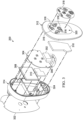
- FIG 3 is an exploded view of the control unit 200, illustrating additional details that may be associated with some embodiments.
- the control unit 200 may include a vacuum pump 302, a printed wiring assembly 304, a valve 306, a power source such as a battery 308, and a mounting foam 310.
- the vacuum pump 302 is an example embodiment of the negative pressure source 104 in Figure 1 .
- some embodiments of the housing 202 may comprise a first housing 312 and a second housing 314, which may be coupled to enclose the vacuum pump 302, the printed wiring assembly 304, the valve 306, the battery 308, and the mounting foam 310.
- the first housing 312 may include controls 316 and an interface overlay 318, which may be attached to a control panel 320 over the controls 316 to form the interface 204 in some embodiments.
- the control unit 200 may also include a seal 322.
- An expansion chamber 324 may also be coupled to or otherwise disposed in the second housing 314 in some embodiments of the control unit 200.
- the mounting foam 310 is preferably a low-density foam, which can positioned between the vacuum pump 302 and the housing 202.
- Illustrative examples of the mounting foam 310 include a melamine, polyester polyurethane, or impregnated polyether foam with a density approximately in the range of 10-100 kilograms per cubic meter.
- the mounting foam 310 may have an adhesive backing or may be pre-bonded to the first housing 312 and the second housing 314 in some embodiments to simplify assembly.
- the seal 322 preferably comprises a material that is relatively pliable and impermeable to fluid.
- the seal 322 may be manufactured from a non-porous polyester film, preferably having a thickness between 0.1 millimeter and 0.2 millimeter.
- the seal 322 also preferably comprises an adhesive or other suitable means for attaching the seal 322 to the second housing 314.
- the seal 322 may include an acrylic adhesive applied to one side, preferably having a thickness of about 0.15 millimeters.
- the seal 322 may also be an adhesive label or integrated with product labeling.
- the expansion chamber 324 is preferably sealed to retain any condensation from humid air flowing through the expansion chamber in operation.
- the mounting foam 310 may be compressed against the upper edges of the expansion chamber 324 to fluidly isolate the interior of the expansion chamber 324 from other components, particularly components that may be adversely affected by moisture.
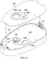
- Figure 4 is an exploded view of the second housing 314 and the seal 322.
- some embodiments of the second housing 314 may include one or more fluid channels.
- the second housing 314 may comprise a panel 402, and fluid channels 404a-404c may be integrated into the panel 402.
- the fluid channels 404a-404c may be open channels, as shown in Figure 4 .
- Such open channels may, for example, be formed as a groove, furrow, cut, depression, or gutter in the panel 402.
- the fluid channels 404a-404c may have rectangular, semi-circular, or trapezoidal cross-sections, for example.
- a canister port 406 may also be coupled to the second housing 314.
- the canister port 406 may be integral to the panel 402, and may also be fluidly coupled to one or more of the fluid channels, such as the fluid channel 404a.
- the seal 322 may also have apertures such as apertures 408a-408c, which can be aligned with various features in the second housing 314.
- the aperture 408a may be aligned with the canister port 406, and the aperture 408b may be aligned and fluidly coupled with a terminus or other portion of the fluid channel 404b.
- a gasket 410 may also be coupled to the seal 322 around the aperture 408a, the aperture 408b, the aperture 408c, or any combination thereof.
- the second housing 314 may also include a canister latch 412 to facilitate fastening the second housing 314 to a canister.
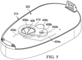
- Figure 5 is a perspective view of the second housing 314 assembled with the seal 322. Assembled as shown in the example embodiment of Figure 5 , the seal 322 is attached to the panel 402 and covers the fluid channels 404a-404c. In some embodiments, the seal 322 may not cover all of the fluid channels 404a-404c. Rather, in some example embodiments, the seal 322 may only cover one or two of the fluid channels 404a-404c, and additional seals may be attached to the panel 402 to cover individual fluid channels. The seal 322 preferably provides a margin of at least 5 millimeters around the perimeter of a channel. Although the seal 322 may be transparent in some embodiments, the fluid channels 404a-404c are shown as hidden lines in Figure 5. Figure 5 also illustrates the alignment of aperture 408a with the canister port 406 in this example embodiment, and further illustrates the alignment of the aperture 408b with an intermediate portion of the fluid channel 404b.
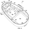
- Figure 6 is a perspective view of the second housing 314 from the opposite side of Figure 5 , illustrating additional details that may be associated with some embodiments.
- the second housing 314 may include partitions 602 that partition the second housing 314 into compartments, such as a battery compartment 604 and a pump compartment 606.
- One or more of the partitions 602 may also form at least part of the expansion chamber 324, as illustrated in the example embodiment of Figure 6 .
- some embodiments of the expansion chamber 324 may include one or more baffles 607.
- the baffles 607 may be a panel, plate, wall or other partition, for example, disposed in the expansion chamber 324 to direct the flow of fluid or otherwise define a fluid path.
- the baffles 607 are preferably substantially impervious to fluid, and may be configured to increase sound attenuation by reflecting sound waves and directing fluid along a tortuous or serpentine path, for example.
- channel extensions 608a-608c may be ridges or ribs that track the fluid channels 404a-404c in the panel 402, which can provide additional depth to the fluid channels.
- at least one fluid port may also be coupled to the panel 402.
- a channel port 610 may be integrated into the channel extension 608a.
- a fluid port, such as the channel port 610, may include either a male or female connector.
- the channel port 610 illustrated in the example embodiment of Figure 6 may include a single male fitting, which generally comprises a protruding body such as a bolt, post, or mounting boss adapted for insertion into a compatible female connector, receptacle, or lumen.
- the example embodiment of Figure 6 also includes a channel port 612, a channel port 614, and a channel port 616, which can include features similar or analogous to the channel port 610.
- Figure 7 is a plan view of the second housing 314 of Figure 6 , illustrating additional details that may be associated with some example embodiments.
- Figure 7 further illustrates a relationship between the fluid channels 404a-404c, which are shown as hidden lines in Figure 7 , and the channel extensions 608a-608c. More specifically, in the example embodiment of Figure 7 , a longitudinal axis of each of the channel extensions 608a-608c can be aligned with a respective longitudinal axis of the fluid channels 404a-404c.
- Figure 7 also illustrates example embodiments of the channel port 610, the channel port 612, the channel port 614, and the channel port 616.
- one end of the fluid channel 404a can be fluidly coupled to the canister port 406 and an opposing end of the fluid channel 404a can be fluidly coupled to the channel port 612.
- a channel port may be fluidly coupled to each terminus of a fluid channel.
- the channel port 614 can be fluidly coupled to a first terminus of the fluid channel 404b and a channel port 618 may be fluidly coupled to a second terminus of the fluid channel 404b.
- One or more channel ports may also be fluidly coupled to a fluid channel between each terminus.
- the channel port 610 may be fluidly coupled to an intermediate point of the fluid channel 404a.
- Figure 8 is a section view of the second housing 314 and the seal 322 taken along line 8-8 of Figure 7 , illustrating additional details that may be associated with some embodiments.
- the fluid channel 404c extends across a proximal end of the partition 602.
- the seal 322 may be secured to the panel 402, as shown in Figure 8 .
- the seal 322 also covers the fluid channel 404c to form an integrated fluid conductor between the expansion chamber 324 and the channel port 616.
- the seal 322 may also cover other fluid channels, such as the fluid channel 404a, the fluid channel 404b, or both, to form additional fluid conductors in the panel 402.
- a seal such as the seal 322 preferably covers and seals the fluid channels completely. In operation, a channel is preferably deep enough to ensure that deformation of the seal under negative pressure does not cause the seal to block the channel.
- Figure 9 is a detail view of a section of Figure 8 .
- some embodiments of the port 616 may include an alignment post 902 and a fluid conductor, such as a passage 904.
- the passage 904 may be coupled to the fluid channel 404c, which can be fluidly coupled to the expansion chamber 324 through the fluid channel 404c and a passage 906 in the panel 402.
- the seal 322 spans the fluid channel 404c in this embodiment to form an enclosed fluid conductor integral to the panel 402.
- the second housing 314 may be manufactured with a molding process, such as injection molding.
- a mold preferably comprises two blocks machined to jointly provide a cavity having the shape and features of a part.
- a part preferably consists only of surfaces that allow a mold to be separated with a straight pull on the mold in at least one orientation. For example, an undercut on a part can prevent a straight pull on a mold, or may require a side pull that can increase the complexity and cost of manufacturing.
- a part design may be visually inspected to identify undercuts or other features that may interfere with a straight pull mold in a particular orientation.
- Surface designs can also be analyzed by considering each line in a solid model, to determine if each line is continuous and intersects the part surface profile only at a single beginning and a single ending.
- An example of an automated geometric analysis of a solid model is described by Lukis et al. in U.S. 8,140,401 .
- Surfaces can also be characterized by the angle between the surface and the direction of pull, referred to herein as the "parting angle." In this context, the parting angle of a surface is equal to ninety degrees minus the angle between the direction of pull and a line that is normal to the surface and intersects the direction of pull.
- a surface that is parallel to the direction of pull has a parting angle of zero degrees
- a surface that is perpendicular to the direction of pull and facing the direction of pull has a parting angle of ninety degrees.
- An undercut may also be characterized by a parting angle.
- a surface that is perpendicular to the direction of pull but faces away from the direction of pull has a parting angle of negative ninety degrees (ninety degrees minus 180 degrees).
- an undercut has a parting angle less than zero degrees (a negative parting angle), and a part may be characterized as consisting only of straight-pull surfaces if all of the surfaces have a parting angle that is greater than or equal to zero degrees (a positive parting angle) in at least one orientation.
- the second housing 314 may consist entirely of straight-pull surfaces, which can be manufactured with a straight-pull mold in at least one orientation.
- the direction of pull may be perpendicular to the panel 402
- the panel 402 including the fluid channels 404a-404c
- the panel 402 may consist of surfaces without overhangs or undercuts, which can be manufactured with a straight-pull mold opened perpendicular to the panel 402.
- Fluid ports, such as the fluid port 610, and channel extensions, such as the channel extensions 608a-608c may also be designed without undercuts to facilitate straight-pull injection molding.
- the panel 402 is generally illustrated as integral to the second housing 314, the panel 402 may also be manufactured separately and fastened to the second housing 314 in some embodiments.
- the first housing 312 and other parts of the control unit 200 may also consist of straight-pull surfaces to reduce manufacturing complexity and cost.
- FIG 10 is a perspective view of the second housing 314 partially assembled with the vacuum pump 302, the printed wiring assembly 304, and the valve 306.
- the vacuum pump 302 may include a negative-pressure port 1002 and a positive-pressure port 1004.
- the vacuum pump 302 may produce a vacuum at the negative-pressure port 1002 and exhaust fluid under positive pressure at the positive-pressure port 1004.
- the negative-pressure port 1002 may be fluidly coupled to the fluid channel 404a
- the positive-pressure port 1004 may be fluidly coupled to the fluid channel 404c.
- a tube 1006 may fluidly couple the negative-pressure port 1002 to the fluid channel 404a through the channel port 610, and a tube 1008 may fluidly couple the positive-pressure port 1004 to the fluid channel 404c through the channel port 616.
- Figure 11 is a section view of the assembly of Figure 10 taken along line 11-11, illustrating additional details that may be associated with some embodiments.
- Figure 11 illustrates an interface between the printed wiring assembly 304 and the channel ports 612 and 614.
- the printed wiring assembly 304 may include pneumatic sensors, such as a pressure transducer 1102 having a transducer port 1104 and a second pressure transducer 1106 having a transducer port 1108.
- the transducer port 1104 may be inserted into the channel port 612 and the transducer port 1108 may be inserted into the channel port 614, as illustrated in the example of Figure 11 .
- FIG. 11 Although only two connections are illustrated in the section view of Figure 11 , similar principles may be readily applied to connect other components, such as the pump 302.
- Figure 12 is an exploded view of Figure 10 , illustrating additional details that may be associated with some embodiments.
- Figure 12 further illustrates the pressure transducer 1102 and the pressure transducer 1106.
- the transducer port 1104 may be configured to be press-fit into the channel port 612, for example, and the transducer port 1108 may be similarly configured to be press-fit into the channel port 614.
- the pressure transducer 1102 may also comprise electrical conductors, such as conductive pins 1202, configured to be coupled to a compatible port (not shown in Figure 12 ) on the printed wiring assembly 304.
- the pressure transducer 1106 may include similar or analogous pins 1204.
- Figure 13 is a section view of another example embodiment of a fluid coupling between two components.
- Figure 13 illustrates a housing 1302, a channel port 1304, a channel port 1306, and a printed wiring assembly 1308, which may be similar or analogous to the second housing 314, the channel port 612, the channel port 614, and the printed wiring assembly 304, respectively.
- a first fitting 1310 can join the channel port 1304 to a pneumatic component of the printed wiring assembly 1308, such as a first pressure transducer 1312.
- a second fitting 1314 can join the channel port 1306 to another pneumatic component, such as a second pressure transducer 1316.
- Fittings such as the first fitting 1310 and the second fitting 1314 may be constructed from a thermoplastic elastomer or similar flexible material, which can provide an interference fit between the fittings and respective pneumatic components.
- a yoke 1318 can join the first fitting 1310 and the second fitting 1314, which can be fabricated as a single unit.
- Fittings may also be over-molded as part of the housing 1302 in some embodiments, but in other embodiments fittings may be fabricated separately and press-fit onto the housing 1302. Although only two fittings are illustrated in the section view of Figure 13 , similar principles may be readily applied to connect other components, and more than two fittings may be fabricated as a single unit similar or analogous to the fittings illustrated in Figure 13 .
- Figure 14 is a perspective view of another example of a housing 1402 that may be associated with some embodiments of a control unit, such as the control unit 200 of Figure 2 .
- the housing 1402 may be similar or analogous to the housing 202, and may include any combination of the features of the housing 202.
- the housing 1402 may have a first housing 1404, a second housing 1406, and a panel 1408 with integrated fluid channels, analogous to the first housing 312, the second housing 314, and the panel 402, respectively.
- Figure 14 illustrates the first housing 1404 assembled with the second housing 1406, and the seal 322 secured to the panel 1408.
- a canister port 1410 may also be coupled the panel 1408.
- the canister port 1410 may be integral to the panel 1408, and may also be fluidly coupled to one or more of the fluid channels.
- a fluid channel 1412 may be fluidly coupled to an exhaust port of a vacuum pump (not shown in Figure 14 ).
- the fluid channel 1412 may be curved or serpentine to increase the length of the fluid channel 1412, analogous to the baffles 307, which can effectively reduce pressure peaks and sound level of exhaust flow.
- the diameter of the fluid channel 1412 can also be adjusted in some embodiments to reduce the sound level.
- Fluid may be vented through an aperture 1414 in the seal 322 over the fluid channel 1412, preferably at a downstream extremity of the fluid channel 1412.
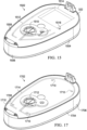
- Figure 15 is a perspective view of another embodiment of a housing 1502 that may be associated with some embodiments of a control unit, such as the control unit 200.
- the housing 1502 may be similar or analogous to the housing 202, and may include any combination of the features of the housing 202.
- the housing 1502 may have a first housing 1504, a second housing 1506, and a panel 1508 with integrated fluid channels, analogous to the first housing 312, the second housing 314, and the panel 402, respectively.
- Figure 15 illustrates the first housing 1504 assembled to the second housing 1506, and the seal 322 secured to the panel 1508.
- a canister port 1510 may also be coupled the housing 1502.
- the canister port 1510 may be integral to the panel 1508, and may also be fluidly coupled to one or more of the fluid channels.
- the fluid channel 1512 may be fluidly coupled to an exhaust port of a vacuum pump (not shown in Figure 15 ).
- the fluid channel 1512 may also be fluidly coupled to an expansion chamber 1514, analogous to the expansion chamber 324.
- the expansion chamber 1514 is an open chamber.
- the fluid capacity of the expansion chamber 1514 is preferably sufficiently large to dissipate exhaust pressure delivered through the fluid channel 1512.
- the expansion chamber 1514 may also include baffles or sound-absorbing foam to further reduce sound produced by exhaust flow from a vacuum pump. Fluid may be vented through an aperture 1516 in the seal 322 over the expansion chamber 1514.
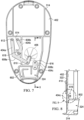
- FIG 16 is a perspective view of yet another example of a housing 1602 that may be associated with some embodiments of a control unit, such as the control unit 200.
- the housing 1602 may be similar or analogous to the second housing 314, and may include any combination of the features of the second housing 314.
- the housing 1602 may include a pump chamber 1604, analogous to the pump compartment 606 in the example embodiment of Figure 6 .
- a vacuum pump 1606 may be disposed in the pump chamber 1604.
- the vacuum pump 1606 may include a vacuum port 1608, which may be fluidly coupled through a tube or other fluid conductor (not shown in Figure 16 ) to a fluid port 1610 to deliver negative-pressure to other components.
- Positive-pressure fluid may be exhausted from the vacuum pump 1606 through an exhaust port 1612 directly into the pump chamber 1604, and then vented through an aperture 1614 in the housing 1602. Exhausting fluid directly into the pump chamber 1604 can reduce the number of fluid connections in some embodiments.
- Figure 17 is a perspective view of another example embodiment of a housing 1702 that may be associated with a control unit, such as the control unit 200.
- the housing 1702 may be similar or analogous to the housing 202, and may include any combination of the features of the housing 202.
- the housing 1702 may have a first housing 1704, a second housing 1706, and a panel 1708 with integrated fluid channels, analogous to the first housing 312, the second housing 314, and the panel 402, respectively.
- Figure 17 illustrates the first housing 1704 assembled with the second housing 1706, and the seal 322 secured to the panel 1708.
- Fasteners (not visible in Figure 17 ) may be inserted through holes 1710 in the panel 1708 to secure the first housing 1704 to the second housing 1706.
- Suitable fasteners may include screws, clips, or pins, for example.
- the housing 1702 may also have a canister port 1712.
- the seal 322 and a fluid channel 1714 can provide an integrated fluid conductor between a negative-pressure source (not shown) and the canister port 1712.
- a substantial portion of the fluid channel 1714 tracks a perimeter of the panel 1708.
- the holes 1710 may be disposed in the panel 1704 interior to the fluid channel 1714, so that an attempt to remove the seal 322 to remove the fasteners may create a leak in the fluid conductor between a negative-pressure source and the canister port 1712. Such a leak can effectively prevent application of negative-pressure therapy in some embodiments, or an appropriate alarm may be generated upon detecting such a leak.
- control unit 200 may be coupled to a canister, such as the container 112 of Figure 1 , which can be fluidly coupled to a dressing, such as the dressing 102 of Figure 1 .
- the vacuum pump 302 can produce a prescribed negative pressure, which can be distributed to the canister through the canister port 406. The negative pressure can then be distributed through the canister to the dressing.
- the vacuum pump 302 may be a reciprocating pump.
- this type of pump typically emits exhaust pulses, which can be a significant source of noise. Noise can be particularly problematic in smaller pumps that produce relatively high airflow rates, since smaller pumps generally rotate at a higher speed to produce higher flow rates. Excessive noise can interfere with patient compliance, particularly in public places or at night.
- a plenum or extended exhaust pathway such as illustrated by the expansion chamber 324, the fluid channel 1412, or the expansion chamber 1514, can reduce pressure peaks of exhaust flow, reducing the sound level of an apparatus without significantly increase the size or cost of an apparatus.
- Baffles, sound-absorbing foam, or both may additionally or alternatively be used to reduce the sound level.
- exhaust air from the positive-pressure port 1004 of the vacuum pump 302 may enter the expansion chamber 324 through the channel port 616.
- sound waves may be reflected and interfere with each other, which can significantly reduce the sound level, before leaving the expansion chamber 324 through an aperture in the panel 402.
- the mounting foam 310 which can seal the expansion chamber 324 in some embodiments, can also absorb sound waves to further reduce the sound level of an apparatus.
- the housing 202 can eliminate undercuts so that it can be molded with open-and-shut tooling, which can be significantly less expensive than other manufacturing processes.
- Fluid channels may also be integrated into an outer surface of the housing 202 to make desired fluid connections between components, which can significantly reduce the number of parts in a system. Reducing the number of parts can also reduce the cost and complexity of manufacturing.
- reducing the use of ancillary tubing can also reduce the risk of connections blocked by twisted or bent tubes.
- some embodiments can combine integrated fluid channels with a custom fitting configured to make multiple fluid connections.
Claims (4)
- Appareil permettant de fournir une thérapie par pression négative, l'appareil comprenant :un premier logement (312) ;un second logement (314) ;un panneau (402) accouplé au second logement (314) ;un premier canal de fluide (404a) intégré dans le panneau (402) ;un second canal de fluide (404c) intégré dans le panneau (402) ;un premier orifice de canal (610) intégré dans le panneau (402) et accouplé fluidiquement au premier canal de fluide (404a) ;un second orifice de canal (616) intégré dans le panneau et accouplé fluidiquement au second canal de fluide (404c) ; etune pompe (302) disposée entre le premier logement (312) et le second logement (314), la pompe (302) comprenant un orifice de pression négative (1002) accouplé fluidiquement au premier orifice de canal (610) ;l'appareil étant caractérisé parla pompe comprenant un orifice de pression positive (1004) accouplé fluidiquement au second orifice de canal (616) ;un orifice de cartouche (406) accouplé au panneau (402) et accouplé fluidiquement au premier canal de fluide (404a) en amont de l'orifice de pression négative (1002) ;une chambre d'expansion (324) accouplée au panneau (402) et accouplée fluidiquement au second canal de fluide (404c) en aval de l'orifice à pression positive (1004) ; etune étiquette adhésive (322) accouplée au panneau (402) sur le premier canal de fluide (404a) et le second canal de fluide (404c).
- Appareil selon la revendication 1, dans lequel le panneau (402), le premier canal de fluide (404a), le premier orifice de canal (610), le second canal de fluide (404c), le second orifice de canal (616), l'orifice de cartouche (406), et la chambre d'expansion (324) sont constitués de surfaces ayant un angle de séparation positif dans au moins une orientation.
- Appareil selon la revendication 1, comprenant en outre un réservoir de fluide (112) accouplé fluidiquement à l'orifice de cartouche (406).
- Appareil selon la revendication 1, comprenant en outre :un réservoir de fluide (112) accouplé fluidiquement à l'orifice de cartouche (406) ; etun pansement accouplé fluidiquement au réservoir de fluide (112).
Applications Claiming Priority (3)
| Application Number | Priority Date | Filing Date | Title |
|---|---|---|---|
| US201462048638P | 2014-09-10 | 2014-09-10 | |
| PCT/US2015/049240 WO2016040520A1 (fr) | 2014-09-10 | 2015-09-09 | Appareil de thérapie à conducteurs de fluide intégrés et atténuation de bruit |
| EP15770707.6A EP3191150B1 (fr) | 2014-09-10 | 2015-09-09 | Appareil de thérapie à conducteurs de fluide intégrés et atténuation de bruit |
Related Parent Applications (2)
| Application Number | Title | Priority Date | Filing Date |
|---|---|---|---|
| EP15770707.6A Division EP3191150B1 (fr) | 2014-09-10 | 2015-09-09 | Appareil de thérapie à conducteurs de fluide intégrés et atténuation de bruit |
| EP15770707.6A Division-Into EP3191150B1 (fr) | 2014-09-10 | 2015-09-09 | Appareil de thérapie à conducteurs de fluide intégrés et atténuation de bruit |
Publications (3)
| Publication Number | Publication Date |
|---|---|
| EP3590555A2 EP3590555A2 (fr) | 2020-01-08 |
| EP3590555A3 EP3590555A3 (fr) | 2020-04-08 |
| EP3590555B1 true EP3590555B1 (fr) | 2023-08-30 |
Family
ID=54197072
Family Applications (2)
| Application Number | Title | Priority Date | Filing Date |
|---|---|---|---|
| EP19193338.1A Active EP3590555B1 (fr) | 2014-09-10 | 2015-09-09 | Appareil de thérapie à conducteurs de fluide intégrés et atténuation de bruit |
| EP15770707.6A Active EP3191150B1 (fr) | 2014-09-10 | 2015-09-09 | Appareil de thérapie à conducteurs de fluide intégrés et atténuation de bruit |
Family Applications After (1)
| Application Number | Title | Priority Date | Filing Date |
|---|---|---|---|
| EP15770707.6A Active EP3191150B1 (fr) | 2014-09-10 | 2015-09-09 | Appareil de thérapie à conducteurs de fluide intégrés et atténuation de bruit |
Country Status (7)
| Country | Link |
|---|---|
| US (2) | US10478536B2 (fr) |
| EP (2) | EP3590555B1 (fr) |
| JP (1) | JP6787883B2 (fr) |
| CN (2) | CN107073180B (fr) |
| AU (1) | AU2015315099B2 (fr) |
| CA (1) | CA2960668A1 (fr) |
| WO (1) | WO2016040520A1 (fr) |
Families Citing this family (22)
| Publication number | Priority date | Publication date | Assignee | Title |
|---|---|---|---|---|
| WO2016103032A1 (fr) | 2014-12-22 | 2016-06-30 | Smith & Nephew Plc | Appareil et procédés de thérapie par pression négative |
| HUE049136T2 (hu) | 2015-04-27 | 2020-08-28 | Smith & Nephew | Csökkentett nyomású berendezések |
| JP1586116S (fr) | 2016-02-29 | 2017-09-19 | ||
| CN109069301B (zh) | 2016-03-07 | 2021-11-30 | 史密夫及内修公开有限公司 | 利用整合到伤口敷料中的负压源的伤口治疗设备和方法 |
| EP4049692A1 (fr) | 2016-04-26 | 2022-08-31 | Smith & Nephew PLC | Pansements pour plaies et procédés d'utilisation avec source de pression négative intégrée dotée d'un composant d'inhibition d'entrée de fluide |
| WO2017191158A1 (fr) | 2016-05-03 | 2017-11-09 | Smith & Nephew Plc | Systèmes et procédés pour commander des sources de pression négative dans des systèmes de traitement par pression négative |
| JP6975170B2 (ja) | 2016-05-03 | 2021-12-01 | スミス アンド ネフュー ピーエルシーSmith & Nephew Public Limited Company | 陰圧療法システムにおける陰圧源への電力伝送の最適化 |
| WO2017191154A1 (fr) | 2016-05-03 | 2017-11-09 | Smith & Nephew Plc | Activation et commande d'un dispositif de traitement des plaies par pression négative |
| EP3503857B1 (fr) | 2016-08-25 | 2024-04-17 | Smith & Nephew plc | Pansement absorbant de thérapie par pression négative pour les plaies |
| WO2018060417A1 (fr) | 2016-09-30 | 2018-04-05 | Smith & Nephew Plc | Appareils et procédés de traitement de plaies par pression négative avec électronique intégrée |
| EP3592312B1 (fr) | 2017-03-08 | 2024-01-10 | Smith & Nephew plc | Commande de dispositif de traitement de plaie par pression négative en présence d'une condition de défaillance |
| US11160915B2 (en) | 2017-05-09 | 2021-11-02 | Smith & Nephew Plc | Redundant controls for negative pressure wound therapy systems |
| GB201718070D0 (en) | 2017-11-01 | 2017-12-13 | Smith & Nephew | Negative pressure wound treatment apparatuses and methods with integrated electronics |
| EP3681550B1 (fr) | 2017-09-13 | 2023-11-08 | Smith & Nephew PLC | Appareils de traitement de plaies par pression négative avec électronique intégrée |
| GB201718072D0 (en) | 2017-11-01 | 2017-12-13 | Smith & Nephew | Negative pressure wound treatment apparatuses and methods with integrated electronics |
| EP3703632B1 (fr) | 2017-11-01 | 2024-04-03 | Smith & Nephew plc | Appareils et procédés de traitement de plaies par pression négative avec électronique intégrée |
| GB201718054D0 (en) | 2017-11-01 | 2017-12-13 | Smith & Nephew | Sterilization of integrated negative pressure wound treatment apparatuses and sterilization methods |
| US20210162106A1 (en) * | 2018-06-28 | 2021-06-03 | Kci Licensing, Inc. | Negative-pressure therapy unit with noise attenuation and integrated seal |
| USD898925S1 (en) | 2018-09-13 | 2020-10-13 | Smith & Nephew Plc | Medical dressing |
| USD895787S1 (en) * | 2019-05-10 | 2020-09-08 | Kci Licensing, Inc. | Negative pressure therapy device |
| US20210207705A1 (en) * | 2020-01-06 | 2021-07-08 | GM Global Technology Operations LLC | Integrated oil capture and gasket system |
| WO2023237973A1 (fr) * | 2022-06-10 | 2023-12-14 | 3M Innovative Properties Company | Dispositif de pression négative universel, support et système |
Family Cites Families (181)
| Publication number | Priority date | Publication date | Assignee | Title |
|---|---|---|---|---|
| US1355846A (en) | 1920-02-06 | 1920-10-19 | David A Rannells | Medical appliance |
| US2547758A (en) | 1949-01-05 | 1951-04-03 | Wilmer B Keeling | Instrument for treating the male urethra |
| US2632443A (en) | 1949-04-18 | 1953-03-24 | Eleanor P Lesher | Surgical dressing |
| GB692578A (en) | 1949-09-13 | 1953-06-10 | Minnesota Mining & Mfg | Improvements in or relating to drape sheets for surgical use |
| US2682873A (en) | 1952-07-30 | 1954-07-06 | Johnson & Johnson | General purpose protective dressing |
| NL189176B (nl) | 1956-07-13 | 1900-01-01 | Hisamitsu Pharmaceutical Co | Pleister op basis van een synthetische rubber. |
| US2969057A (en) | 1957-11-04 | 1961-01-24 | Brady Co W H | Nematodic swab |
| US3066672A (en) | 1960-09-27 | 1962-12-04 | Jr William H Crosby | Method and apparatus for serial sampling of intestinal juice |
| US3367332A (en) | 1965-08-27 | 1968-02-06 | Gen Electric | Product and process for establishing a sterile area of skin |
| US3520300A (en) | 1967-03-15 | 1970-07-14 | Amp Inc | Surgical sponge and suction device |
| US3568675A (en) | 1968-08-30 | 1971-03-09 | Clyde B Harvey | Fistula and penetrating wound dressing |
| US3682180A (en) | 1970-06-08 | 1972-08-08 | Coilform Co Inc | Drain clip for surgical drain |
| BE789293Q (fr) | 1970-12-07 | 1973-01-15 | Parke Davis & Co | Pansement medico-chirugical pour brulures et lesions analogues |
| US3826254A (en) | 1973-02-26 | 1974-07-30 | Verco Ind | Needle or catheter retaining appliance |
| US3888331A (en) * | 1974-05-03 | 1975-06-10 | Gen Motors Corp | Power tuned wave interference silencer |
| DE2527706A1 (de) | 1975-06-21 | 1976-12-30 | Hanfried Dr Med Weigand | Einrichtung zum einleiten von kontrastmittel in einen kuenstlichen darmausgang |
| DE2640413C3 (de) | 1976-09-08 | 1980-03-27 | Richard Wolf Gmbh, 7134 Knittlingen | Katheter-Überwachungsgerät |
| NL7710909A (nl) | 1976-10-08 | 1978-04-11 | Smith & Nephew | Samengestelde hechtstrook. |
| GB1562244A (en) | 1976-11-11 | 1980-03-05 | Lock P M | Wound dressing materials |
| US4080970A (en) | 1976-11-17 | 1978-03-28 | Miller Thomas J | Post-operative combination dressing and internal drain tube with external shield and tube connector |
| US4139004A (en) | 1977-02-17 | 1979-02-13 | Gonzalez Jr Harry | Bandage apparatus for treating burns |
| US4184510A (en) | 1977-03-15 | 1980-01-22 | Fibra-Sonics, Inc. | Valued device for controlling vacuum in surgery |
| US4161264A (en) * | 1977-06-17 | 1979-07-17 | Johnson Bryan E | Fluid metering and mixing device having inlet and outlet valves |
| US4165748A (en) | 1977-11-07 | 1979-08-28 | Johnson Melissa C | Catheter tube holder |
| US4256109A (en) | 1978-07-10 | 1981-03-17 | Nichols Robert L | Shut off valve for medical suction apparatus |
| SE414994B (sv) | 1978-11-28 | 1980-09-01 | Landstingens Inkopscentral | Venkateterforband |
| BR7908937A (pt) | 1978-12-06 | 1981-06-30 | Svedman Paul | Dispositivo para tratamento de tecidos,por exemplo,pele |
| US4266545A (en) | 1979-04-06 | 1981-05-12 | Moss James P | Portable suction device for collecting fluids from a closed wound |
| US4284079A (en) | 1979-06-28 | 1981-08-18 | Adair Edwin Lloyd | Method for applying a male incontinence device |
| US4261363A (en) | 1979-11-09 | 1981-04-14 | C. R. Bard, Inc. | Retention clips for body fluid drains |
| US4569348A (en) | 1980-02-22 | 1986-02-11 | Velcro Usa Inc. | Catheter tube holder strap |
| ATE14835T1 (de) | 1980-03-11 | 1985-08-15 | Schmid Eduard | Hauttransplantations-druckverband. |
| US4297995A (en) | 1980-06-03 | 1981-11-03 | Key Pharmaceuticals, Inc. | Bandage containing attachment post |
| US4333468A (en) | 1980-08-18 | 1982-06-08 | Geist Robert W | Mesentery tube holder apparatus |
| US4465485A (en) | 1981-03-06 | 1984-08-14 | Becton, Dickinson And Company | Suction canister with unitary shut-off valve and filter features |
| US4392853A (en) | 1981-03-16 | 1983-07-12 | Rudolph Muto | Sterile assembly for protecting and fastening an indwelling device |
| US4373519A (en) | 1981-06-26 | 1983-02-15 | Minnesota Mining And Manufacturing Company | Composite wound dressing |
| US4392858A (en) | 1981-07-16 | 1983-07-12 | Sherwood Medical Company | Wound drainage device |
| US4419097A (en) | 1981-07-31 | 1983-12-06 | Rexar Industries, Inc. | Attachment for catheter tube |
| AU550575B2 (en) | 1981-08-07 | 1986-03-27 | Richard Christian Wright | Wound drainage device |
| SE429197B (sv) | 1981-10-14 | 1983-08-22 | Frese Nielsen | Anordning for behandling av sar |
| DE3146266A1 (de) | 1981-11-21 | 1983-06-01 | B. Braun Melsungen Ag, 3508 Melsungen | Kombinierte vorrichtung fuer eine medizinische saugdrainage |
| US4551139A (en) | 1982-02-08 | 1985-11-05 | Marion Laboratories, Inc. | Method and apparatus for burn wound treatment |
| US4475909A (en) | 1982-05-06 | 1984-10-09 | Eisenberg Melvin I | Male urinary device and method for applying the device |
| EP0100148B1 (fr) | 1982-07-06 | 1986-01-08 | Dow Corning Limited | Pansement médico-chirurgical et son procédé de production |
| NZ206837A (en) | 1983-01-27 | 1986-08-08 | Johnson & Johnson Prod Inc | Thin film adhesive dressing:backing material in three sections |
| US4548202A (en) | 1983-06-20 | 1985-10-22 | Ethicon, Inc. | Mesh tissue fasteners |
| US4540412A (en) | 1983-07-14 | 1985-09-10 | The Kendall Company | Device for moist heat therapy |
| US4543100A (en) | 1983-11-01 | 1985-09-24 | Brodsky Stuart A | Catheter and drain tube retainer |
| US4525374A (en) | 1984-02-27 | 1985-06-25 | Manresa, Inc. | Treating hydrophobic filters to render them hydrophilic |
| GB2157958A (en) | 1984-05-03 | 1985-11-06 | Ernest Edward Austen Bedding | Ball game net support |
| US4897081A (en) | 1984-05-25 | 1990-01-30 | Thermedics Inc. | Percutaneous access device |
| US5215522A (en) | 1984-07-23 | 1993-06-01 | Ballard Medical Products | Single use medical aspirating device and method |
| GB8419745D0 (en) | 1984-08-02 | 1984-09-05 | Smith & Nephew Ass | Wound dressing |
| US4872450A (en) | 1984-08-17 | 1989-10-10 | Austad Eric D | Wound dressing and method of forming same |
| US4655754A (en) | 1984-11-09 | 1987-04-07 | Stryker Corporation | Vacuum wound drainage system and lipids baffle therefor |
| US4826494A (en) | 1984-11-09 | 1989-05-02 | Stryker Corporation | Vacuum wound drainage system |
| US4605399A (en) | 1984-12-04 | 1986-08-12 | Complex, Inc. | Transdermal infusion device |
| US5037397A (en) | 1985-05-03 | 1991-08-06 | Medical Distributors, Inc. | Universal clamp |
| US4640688A (en) | 1985-08-23 | 1987-02-03 | Mentor Corporation | Urine collection catheter |
| US4710165A (en) | 1985-09-16 | 1987-12-01 | Mcneil Charles B | Wearable, variable rate suction/collection device |
| US4758220A (en) | 1985-09-26 | 1988-07-19 | Alcon Laboratories, Inc. | Surgical cassette proximity sensing and latching apparatus |
| US4733659A (en) | 1986-01-17 | 1988-03-29 | Seton Company | Foam bandage |
| EP0256060A1 (fr) | 1986-01-31 | 1988-02-24 | OSMOND, Roger L. W. | Systeme de succion pour drainage de blessures et drainage gastro-intestinal |
| US4838883A (en) | 1986-03-07 | 1989-06-13 | Nissho Corporation | Urine-collecting device |
| JPS62281965A (ja) | 1986-05-29 | 1987-12-07 | テルモ株式会社 | カテ−テルおよびカテ−テル用固定部材 |
| GB8621884D0 (en) | 1986-09-11 | 1986-10-15 | Bard Ltd | Catheter applicator |
| GB2195255B (en) | 1986-09-30 | 1991-05-01 | Vacutec Uk Limited | Apparatus for vacuum treatment of an epidermal surface |
| US4743232A (en) | 1986-10-06 | 1988-05-10 | The Clinipad Corporation | Package assembly for plastic film bandage |
| DE3634569A1 (de) | 1986-10-10 | 1988-04-21 | Sachse Hans E | Kondomkatheter, ein harnroehrenkatheter zur verhinderung von aufsteigenden infektionen |
| JPS63135179A (ja) | 1986-11-26 | 1988-06-07 | 立花 俊郎 | 薬物の経皮投与具 |
| GB8628564D0 (en) | 1986-11-28 | 1987-01-07 | Smiths Industries Plc | Anti-foaming agent suction apparatus |
| GB8706116D0 (en) | 1987-03-14 | 1987-04-15 | Smith & Nephew Ass | Adhesive dressings |
| US4798580A (en) * | 1987-04-27 | 1989-01-17 | Site Microsurgical Systems, Inc. | Disposable peristaltic pump cassette system |
| US4787888A (en) | 1987-06-01 | 1988-11-29 | University Of Connecticut | Disposable piezoelectric polymer bandage for percutaneous delivery of drugs and method for such percutaneous delivery (a) |
| US4863449A (en) | 1987-07-06 | 1989-09-05 | Hollister Incorporated | Adhesive-lined elastic condom cathether |
| US5176663A (en) | 1987-12-02 | 1993-01-05 | Pal Svedman | Dressing having pad with compressibility limiting elements |
| US4906240A (en) | 1988-02-01 | 1990-03-06 | Matrix Medica, Inc. | Adhesive-faced porous absorbent sheet and method of making same |
| US4985019A (en) | 1988-03-11 | 1991-01-15 | Michelson Gary K | X-ray marker |
| US4950235A (en) * | 1988-05-10 | 1990-08-21 | Pacesetter Infusion, Ltd. | Container-side occlusion detection system for a medication infusion system |
| GB8812803D0 (en) | 1988-05-28 | 1988-06-29 | Smiths Industries Plc | Medico-surgical containers |
| US4919654A (en) | 1988-08-03 | 1990-04-24 | Kalt Medical Corporation | IV clamp with membrane |
| US5000741A (en) | 1988-08-22 | 1991-03-19 | Kalt Medical Corporation | Transparent tracheostomy tube dressing |
| DE69017479T2 (de) | 1989-01-16 | 1995-07-13 | Roussel Uclaf | Azabicycloheptenderivate und ihre Salze, Verfahren zu ihrer Herstellung, ihre Verwendung als Arzneimittel und diese enthaltende Zubereitungen. |
| GB8906100D0 (en) | 1989-03-16 | 1989-04-26 | Smith & Nephew | Laminates |
| US4969880A (en) | 1989-04-03 | 1990-11-13 | Zamierowski David S | Wound dressing and treatment method |
| US5261893A (en) | 1989-04-03 | 1993-11-16 | Zamierowski David S | Fastening system and method |
| US5100396A (en) | 1989-04-03 | 1992-03-31 | Zamierowski David S | Fluidic connection system and method |
| US5527293A (en) | 1989-04-03 | 1996-06-18 | Kinetic Concepts, Inc. | Fastening system and method |
| US5358494A (en) | 1989-07-11 | 1994-10-25 | Svedman Paul | Irrigation dressing |
| JP2719671B2 (ja) | 1989-07-11 | 1998-02-25 | 日本ゼオン株式会社 | 創傷被覆材 |
| US5232453A (en) | 1989-07-14 | 1993-08-03 | E. R. Squibb & Sons, Inc. | Catheter holder |
| GB2235877A (en) | 1989-09-18 | 1991-03-20 | Antonio Talluri | Closed wound suction apparatus |
| US5134994A (en) | 1990-02-12 | 1992-08-04 | Say Sam L | Field aspirator in a soft pack with externally mounted container |
| US5092858A (en) | 1990-03-20 | 1992-03-03 | Becton, Dickinson And Company | Liquid gelling agent distributor device |
| US5173577A (en) * | 1990-09-04 | 1992-12-22 | Ap Parts Manufacturing Co. | Stamp formed muffler with low back pressure |
| US5149331A (en) | 1991-05-03 | 1992-09-22 | Ariel Ferdman | Method and device for wound closure |
| US5278100A (en) | 1991-11-08 | 1994-01-11 | Micron Technology, Inc. | Chemical vapor deposition technique for depositing titanium silicide on semiconductor wafers |
| US5636643A (en) | 1991-11-14 | 1997-06-10 | Wake Forest University | Wound treatment employing reduced pressure |
| US5645081A (en) | 1991-11-14 | 1997-07-08 | Wake Forest University | Method of treating tissue damage and apparatus for same |
| US5279550A (en) | 1991-12-19 | 1994-01-18 | Gish Biomedical, Inc. | Orthopedic autotransfusion system |
| US5167613A (en) | 1992-03-23 | 1992-12-01 | The Kendall Company | Composite vented wound dressing |
| FR2690617B1 (fr) | 1992-04-29 | 1994-06-24 | Cbh Textile | Pansement adhesif transparent. |
| DE4306478A1 (de) | 1993-03-02 | 1994-09-08 | Wolfgang Dr Wagner | Drainagevorrichtung, insbesondere Pleuradrainagevorrichtung, und Drainageverfahren |
| US6241747B1 (en) | 1993-05-03 | 2001-06-05 | Quill Medical, Inc. | Barbed Bodily tissue connector |
| US5342376A (en) | 1993-05-03 | 1994-08-30 | Dermagraphics, Inc. | Inserting device for a barbed tissue connector |
| US5344415A (en) | 1993-06-15 | 1994-09-06 | Deroyal Industries, Inc. | Sterile system for dressing vascular access site |
| US5466229A (en) * | 1993-08-06 | 1995-11-14 | Davstar, Inc. | Fluid collection system |
| US5437651A (en) | 1993-09-01 | 1995-08-01 | Research Medical, Inc. | Medical suction apparatus |
| JP2748229B2 (ja) | 1994-01-19 | 1998-05-06 | オリオン機械株式会社 | 消音器 |
| US5549584A (en) | 1994-02-14 | 1996-08-27 | The Kendall Company | Apparatus for removing fluid from a wound |
| US5464391A (en) * | 1994-03-03 | 1995-11-07 | Northgate Technologies Inc. | Irrigation system for a surgical site |
| US5556375A (en) | 1994-06-16 | 1996-09-17 | Hercules Incorporated | Wound dressing having a fenestrated base layer |
| US5607388A (en) | 1994-06-16 | 1997-03-04 | Hercules Incorporated | Multi-purpose wound dressing |
| US5664270A (en) | 1994-07-19 | 1997-09-09 | Kinetic Concepts, Inc. | Patient interface system |
| AU698477B2 (en) | 1994-08-22 | 1998-10-29 | Kci Licensing, Inc. | Wound drainage equipment |
| DE29504378U1 (de) | 1995-03-15 | 1995-09-14 | Mtg Medizinisch Tech Geraeteba | Elektronisch geregelte Niedervakuumpumpe für die Thorax- und Wunddrainage |
| GB9523253D0 (en) | 1995-11-14 | 1996-01-17 | Mediscus Prod Ltd | Portable wound treatment apparatus |
| US5746719A (en) * | 1996-10-25 | 1998-05-05 | Arthur D. Little, Inc. | Fluid flow control system incorporating a disposable pump cartridge |
| US6135116A (en) | 1997-07-28 | 2000-10-24 | Kci Licensing, Inc. | Therapeutic method for treating ulcers |
| AU755496B2 (en) | 1997-09-12 | 2002-12-12 | Kci Licensing, Inc. | Surgical drape and suction head for wound treatment |
| GB9719520D0 (en) | 1997-09-12 | 1997-11-19 | Kci Medical Ltd | Surgical drape and suction heads for wound treatment |
| US6071267A (en) | 1998-02-06 | 2000-06-06 | Kinetic Concepts, Inc. | Medical patient fluid management interface system and method |
| US6458109B1 (en) * | 1998-08-07 | 2002-10-01 | Hill-Rom Services, Inc. | Wound treatment apparatus |
| US6488643B1 (en) | 1998-10-08 | 2002-12-03 | Kci Licensing, Inc. | Wound healing foot wrap |
| US6145160A (en) * | 1998-11-20 | 2000-11-14 | Primus Holdings, L.P. | Tank-type vacuum cleaner |
| US6287316B1 (en) | 1999-03-26 | 2001-09-11 | Ethicon, Inc. | Knitted surgical mesh |
| US6856821B2 (en) | 2000-05-26 | 2005-02-15 | Kci Licensing, Inc. | System for combined transcutaneous blood gas monitoring and vacuum assisted wound closure |
| US7799004B2 (en) | 2001-03-05 | 2010-09-21 | Kci Licensing, Inc. | Negative pressure wound treatment apparatus and infection identification system and method |
| JP3924985B2 (ja) * | 1999-04-15 | 2007-06-06 | 株式会社豊田自動織機 | 圧縮機の吐出脈動減衰装置 |
| US6991643B2 (en) | 2000-12-20 | 2006-01-31 | Usgi Medical Inc. | Multi-barbed device for retaining tissue in apposition and methods of use |
| CN100357599C (zh) * | 1999-09-03 | 2007-12-26 | 巴克斯特国际公司 | 泵送流体的系统 |
| US6261065B1 (en) * | 1999-09-03 | 2001-07-17 | Baxter International Inc. | System and methods for control of pumps employing electrical field sensing |
| US6824533B2 (en) * | 2000-11-29 | 2004-11-30 | Hill-Rom Services, Inc. | Wound treatment apparatus |
| US6764462B2 (en) * | 2000-11-29 | 2004-07-20 | Hill-Rom Services Inc. | Wound treatment apparatus |
| ATE266443T1 (de) | 2000-02-24 | 2004-05-15 | Venetec Int Inc | Universelles katheterbefestigungssystem |
| AU2001261149A1 (en) | 2000-05-11 | 2001-11-20 | Zevex, Inc. | Apparatus and method for preventing free flow in an infusion line |
| US6540705B2 (en) | 2001-02-22 | 2003-04-01 | Core Products International, Inc. | Ankle brace providing upper and lower ankle adjustment |
| US7496528B2 (en) | 2001-12-27 | 2009-02-24 | Proto Labs, Inc. | Automated quoting of molds and molded parts |
| US7846141B2 (en) | 2002-09-03 | 2010-12-07 | Bluesky Medical Group Incorporated | Reduced pressure treatment system |
| GB0224986D0 (en) | 2002-10-28 | 2002-12-04 | Smith & Nephew | Apparatus |
| GB0325126D0 (en) | 2003-10-28 | 2003-12-03 | Smith & Nephew | Apparatus with heat |
| GB0325120D0 (en) | 2003-10-28 | 2003-12-03 | Smith & Nephew | Apparatus with actives |
| US7909805B2 (en) | 2004-04-05 | 2011-03-22 | Bluesky Medical Group Incorporated | Flexible reduced pressure treatment appliance |
| US8529548B2 (en) | 2004-04-27 | 2013-09-10 | Smith & Nephew Plc | Wound treatment apparatus and method |
| JP2006234600A (ja) * | 2005-02-25 | 2006-09-07 | Sumitomo Bakelite Co Ltd | プラスチック製マイクロチップおよびその製造方法 |
| US7563248B2 (en) * | 2005-03-17 | 2009-07-21 | Smisson-Cartledge Biomedical Llc | Infusion fluid heat exchanger and cartridge |
| US7438705B2 (en) * | 2005-07-14 | 2008-10-21 | Boehringer Technologies, L.P. | System for treating a wound with suction and method detecting loss of suction |
| AU2006273684A1 (en) * | 2005-07-24 | 2007-02-01 | Carmeli Adahan | Suctioning system, method and kit |
| EP1909863A1 (fr) * | 2005-07-24 | 2008-04-16 | Carmeli Adahan | Systeme de fermeture et de drainage de plaie |
| US7435284B2 (en) * | 2005-11-17 | 2008-10-14 | Thermo Electron Corporation | Parallel-plate diffusion gas dehumidifier and methods for use |
| CA2867838C (fr) * | 2005-12-14 | 2016-08-02 | Stryker Corporation | Dispositif de collecte et elimination de pate chirurgicale medicale comportant un recipient et une station d'accueil, la station d'accueil presentant des caracteristiques facilitant l'alignement de la station d'accueil et du recipient |
| WO2007087810A2 (fr) * | 2006-02-02 | 2007-08-09 | Coloplast A/S | Procede d'aspiration et systeme de drainage de plaies |
| US7779625B2 (en) * | 2006-05-11 | 2010-08-24 | Kalypto Medical, Inc. | Device and method for wound therapy |
| US20090326488A1 (en) * | 2006-07-24 | 2009-12-31 | Klaus Budig | Canister, Suction Device and System For Vacuum Treatment Securing a Fixed Treatment Pressure |
| CA2872297C (fr) * | 2006-09-28 | 2016-10-11 | Smith & Nephew, Inc. | Systeme portatif pour therapie de blessures |
| GB0712739D0 (en) * | 2007-07-02 | 2007-08-08 | Smith & Nephew | Apparatus |
| GB0723876D0 (en) * | 2007-12-06 | 2008-01-16 | Smith & Nephew | Apparatus and method for topical negative pressure therapy |
| GB0723875D0 (en) * | 2007-12-06 | 2008-01-16 | Smith & Nephew | Wound management |
| US8021347B2 (en) | 2008-07-21 | 2011-09-20 | Tyco Healthcare Group Lp | Thin film wound dressing |
| KR20110005795A (ko) * | 2008-04-04 | 2011-01-19 | 메디칼 비젼 리서치 앤드 디벨롭먼트 에이비 | 반사광을 이용한 액체 내 입자의 측정 장치 |
| US8007481B2 (en) | 2008-07-17 | 2011-08-30 | Tyco Healthcare Group Lp | Subatmospheric pressure mechanism for wound therapy system |
| US8251979B2 (en) | 2009-05-11 | 2012-08-28 | Tyco Healthcare Group Lp | Orientation independent canister for a negative pressure wound therapy device |
| US8216198B2 (en) | 2009-01-09 | 2012-07-10 | Tyco Healthcare Group Lp | Canister for receiving wound exudate in a negative pressure therapy system |
| JP5492207B2 (ja) * | 2008-08-27 | 2014-05-14 | ライフ テクノロジーズ コーポレーション | 生物学的サンプルの処理装置および処理方法 |
| US8486032B2 (en) * | 2008-12-24 | 2013-07-16 | Kci Licensing, Inc. | Reduced-pressure treatment systems and methods employing debridement mechanisms |
| US8529526B2 (en) * | 2009-10-20 | 2013-09-10 | Kci Licensing, Inc. | Dressing reduced-pressure indicators, systems, and methods |
| US8403902B2 (en) * | 2010-05-18 | 2013-03-26 | Kci Licensing, Inc. | Reduced-pressure medical systems and methods employing a moisture processing device |
| GB201015656D0 (en) * | 2010-09-20 | 2010-10-27 | Smith & Nephew | Pressure control apparatus |
| US8992510B2 (en) * | 2011-08-03 | 2015-03-31 | Kci Licensing, Inc. | Reduced-pressure wound dressings |
| WO2013043972A1 (fr) * | 2011-09-23 | 2013-03-28 | Avery Dennison Corporation | Appareil, comportant un orifice pour fluide, pouvant être utilisé en vue du traitement par pression négative de plaies et méthodes associées |
| US9084845B2 (en) * | 2011-11-02 | 2015-07-21 | Smith & Nephew Plc | Reduced pressure therapy apparatuses and methods of using same |
| EP2895213B8 (fr) * | 2012-09-12 | 2017-08-30 | KCI Licensing, Inc. | Systèmes de collecte d'exsudats en thérapie sous pression réduite |
| AU2013334799B2 (en) * | 2012-10-24 | 2018-11-08 | Stryker Corporation | Waste collection system for medical/surgical waste having a mobile chassis with a vacuum pump and a mobile cart with a waste container that is coupled to the chassis with the vacuum pump |
| US20160038658A1 (en) * | 2012-11-26 | 2016-02-11 | Apex Medical Corp. | Fluid collector unit of wound drainage therapy system and collection container thereof |
| CN109701095B (zh) * | 2012-11-26 | 2022-10-28 | 3M创新知识产权公司 | 用于与减压治疗系统一起使用的组合溶液泵和储存系统 |
| US8827035B2 (en) * | 2012-12-03 | 2014-09-09 | Ford Global Technologies, Llc | Conformal transverse muffler |
| US9522230B2 (en) * | 2013-04-10 | 2016-12-20 | BioMime Innovations, LLC | Mechanical leech system |
| US10245392B2 (en) * | 2014-08-08 | 2019-04-02 | Neogenix, Llc | Oxygen concentrating device, wound care apparatus, and treatment methods |
| US11179506B2 (en) * | 2015-02-27 | 2021-11-23 | Cork Medical, Llc | Negative pressure wound therapy pump and canister |
| CA3053326A1 (fr) * | 2016-05-24 | 2017-11-30 | Somavac Medical Solutions, Inc. | Dispositif portatif a reservoir jetable pour recueillir un liquide interne apres une intervention chirurgicale |
-
2015
- 2015-09-09 CN CN201580051431.3A patent/CN107073180B/zh active Active
- 2015-09-09 EP EP19193338.1A patent/EP3590555B1/fr active Active
- 2015-09-09 JP JP2017513071A patent/JP6787883B2/ja active Active
- 2015-09-09 AU AU2015315099A patent/AU2015315099B2/en active Active
- 2015-09-09 CA CA2960668A patent/CA2960668A1/fr not_active Abandoned
- 2015-09-09 EP EP15770707.6A patent/EP3191150B1/fr active Active
- 2015-09-09 CN CN202010421827.5A patent/CN111544671B/zh active Active
- 2015-09-09 US US14/849,321 patent/US10478536B2/en active Active
- 2015-09-09 WO PCT/US2015/049240 patent/WO2016040520A1/fr active Application Filing
-
2019
- 2019-09-26 US US16/584,523 patent/US11771815B2/en active Active
Also Published As
| Publication number | Publication date |
|---|---|
| CN107073180A (zh) | 2017-08-18 |
| JP6787883B2 (ja) | 2020-11-18 |
| WO2016040520A1 (fr) | 2016-03-17 |
| US20160067392A1 (en) | 2016-03-10 |
| EP3590555A2 (fr) | 2020-01-08 |
| JP2017532099A (ja) | 2017-11-02 |
| AU2015315099B2 (en) | 2020-03-05 |
| US20200016302A1 (en) | 2020-01-16 |
| EP3191150A1 (fr) | 2017-07-19 |
| CA2960668A1 (fr) | 2016-03-17 |
| AU2015315099A1 (en) | 2017-03-30 |
| EP3590555A3 (fr) | 2020-04-08 |
| EP3191150B1 (fr) | 2019-10-30 |
| US10478536B2 (en) | 2019-11-19 |
| CN107073180B (zh) | 2020-06-02 |
| US11771815B2 (en) | 2023-10-03 |
| CN111544671A (zh) | 2020-08-18 |
| CN111544671B (zh) | 2023-09-08 |
Similar Documents
| Publication | Publication Date | Title |
|---|---|---|
| US11771815B2 (en) | Therapy apparatus with integrated fluid conductors and noise attenuation | |
| EP3488881B1 (fr) | Thérapie à pression négative dynamique avec instillation | |
| US20190142645A1 (en) | Systems And Methods For Collecting Exudates In Reduced-Pressure Therapy | |
| US20210137745A1 (en) | Dressing bolster with area pressure indicator | |
| US20210267809A1 (en) | Release liner with edge protection | |
| US11123537B2 (en) | Apparatus for irrigation with negative pressure | |
| US20220001094A1 (en) | Negative-pressure therapy with pneumatically-actuated instillation | |
| US20210205143A1 (en) | Dressing Interface, Systems, And Methods | |
| US20210162106A1 (en) | Negative-pressure therapy unit with noise attenuation and integrated seal |
Legal Events
| Date | Code | Title | Description |
|---|---|---|---|
| PUAI | Public reference made under article 153(3) epc to a published international application that has entered the european phase |
Free format text: ORIGINAL CODE: 0009012 |
|
| STAA | Information on the status of an ep patent application or granted ep patent |
Free format text: STATUS: THE APPLICATION HAS BEEN PUBLISHED |
|
| AC | Divisional application: reference to earlier application |
Ref document number: 3191150 Country of ref document: EP Kind code of ref document: P |
|
| AK | Designated contracting states |
Kind code of ref document: A2 Designated state(s): AL AT BE BG CH CY CZ DE DK EE ES FI FR GB GR HR HU IE IS IT LI LT LU LV MC MK MT NL NO PL PT RO RS SE SI SK SM TR |
|
| RIN1 | Information on inventor provided before grant (corrected) |
Inventor name: MERCER, DAVID Inventor name: PRATT, BENJAMIN ANDREW Inventor name: LOCKE, CHRISTOPHER, BRIAN Inventor name: SEDDON, JAMES KILLINGWORTH Inventor name: FRANCIS, LOREN |
|
| PUAL | Search report despatched |
Free format text: ORIGINAL CODE: 0009013 |
|
| AK | Designated contracting states |
Kind code of ref document: A3 Designated state(s): AL AT BE BG CH CY CZ DE DK EE ES FI FR GB GR HR HU IE IS IT LI LT LU LV MC MK MT NL NO PL PT RO RS SE SI SK SM TR |
|
| RIC1 | Information provided on ipc code assigned before grant |
Ipc: A61M 1/00 20060101AFI20200305BHEP Ipc: B29C 33/00 20060101ALI20200305BHEP |
|
| STAA | Information on the status of an ep patent application or granted ep patent |
Free format text: STATUS: REQUEST FOR EXAMINATION WAS MADE |
|
| 17P | Request for examination filed |
Effective date: 20201008 |
|
| RBV | Designated contracting states (corrected) |
Designated state(s): AL AT BE BG CH CY CZ DE DK EE ES FI FR GB GR HR HU IE IS IT LI LT LU LV MC MK MT NL NO PL PT RO RS SE SI SK SM TR |
|
| RAP1 | Party data changed (applicant data changed or rights of an application transferred) |
Owner name: 3M INNOVATIVE PROPERTIES COMPANY |
|
| GRAP | Despatch of communication of intention to grant a patent |
Free format text: ORIGINAL CODE: EPIDOSNIGR1 |
|
| STAA | Information on the status of an ep patent application or granted ep patent |
Free format text: STATUS: GRANT OF PATENT IS INTENDED |
|
| INTG | Intention to grant announced |
Effective date: 20230523 |
|
| GRAS | Grant fee paid |
Free format text: ORIGINAL CODE: EPIDOSNIGR3 |
|
| GRAA | (expected) grant |
Free format text: ORIGINAL CODE: 0009210 |
|
| STAA | Information on the status of an ep patent application or granted ep patent |
Free format text: STATUS: THE PATENT HAS BEEN GRANTED |
|
| AC | Divisional application: reference to earlier application |
Ref document number: 3191150 Country of ref document: EP Kind code of ref document: P |
|
| AK | Designated contracting states |
Kind code of ref document: B1 Designated state(s): AL AT BE BG CH CY CZ DE DK EE ES FI FR GB GR HR HU IE IS IT LI LT LU LV MC MK MT NL NO PL PT RO RS SE SI SK SM TR |
|
| REG | Reference to a national code |
Ref country code: GB Ref legal event code: FG4D |
|
| REG | Reference to a national code |
Ref country code: CH Ref legal event code: EP |
|
| REG | Reference to a national code |
Ref country code: DE Ref legal event code: R096 Ref document number: 602015085494 Country of ref document: DE |
|
| REG | Reference to a national code |
Ref country code: IE Ref legal event code: FG4D |
|
| PGFP | Annual fee paid to national office [announced via postgrant information from national office to epo] |
Ref country code: GB Payment date: 20230920 Year of fee payment: 9 |
|
| PGFP | Annual fee paid to national office [announced via postgrant information from national office to epo] |
Ref country code: DE Payment date: 20230822 Year of fee payment: 9 |
|
| REG | Reference to a national code |
Ref country code: LT Ref legal event code: MG9D |
|
| REG | Reference to a national code |
Ref country code: NL Ref legal event code: MP Effective date: 20230830 |
|
| REG | Reference to a national code |
Ref country code: AT Ref legal event code: MK05 Ref document number: 1604583 Country of ref document: AT Kind code of ref document: T Effective date: 20230830 |
|
| PG25 | Lapsed in a contracting state [announced via postgrant information from national office to epo] |
Ref country code: GR Free format text: LAPSE BECAUSE OF FAILURE TO SUBMIT A TRANSLATION OF THE DESCRIPTION OR TO PAY THE FEE WITHIN THE PRESCRIBED TIME-LIMIT Effective date: 20231201 |
|
| PG25 | Lapsed in a contracting state [announced via postgrant information from national office to epo] |
Ref country code: IS Free format text: LAPSE BECAUSE OF FAILURE TO SUBMIT A TRANSLATION OF THE DESCRIPTION OR TO PAY THE FEE WITHIN THE PRESCRIBED TIME-LIMIT Effective date: 20231230 |
|
| PG25 | Lapsed in a contracting state [announced via postgrant information from national office to epo] |
Ref country code: SE Free format text: LAPSE BECAUSE OF FAILURE TO SUBMIT A TRANSLATION OF THE DESCRIPTION OR TO PAY THE FEE WITHIN THE PRESCRIBED TIME-LIMIT Effective date: 20230830 Ref country code: RS Free format text: LAPSE BECAUSE OF FAILURE TO SUBMIT A TRANSLATION OF THE DESCRIPTION OR TO PAY THE FEE WITHIN THE PRESCRIBED TIME-LIMIT Effective date: 20230830 Ref country code: NO Free format text: LAPSE BECAUSE OF FAILURE TO SUBMIT A TRANSLATION OF THE DESCRIPTION OR TO PAY THE FEE WITHIN THE PRESCRIBED TIME-LIMIT Effective date: 20231130 Ref country code: LV Free format text: LAPSE BECAUSE OF FAILURE TO SUBMIT A TRANSLATION OF THE DESCRIPTION OR TO PAY THE FEE WITHIN THE PRESCRIBED TIME-LIMIT Effective date: 20230830 Ref country code: LT Free format text: LAPSE BECAUSE OF FAILURE TO SUBMIT A TRANSLATION OF THE DESCRIPTION OR TO PAY THE FEE WITHIN THE PRESCRIBED TIME-LIMIT Effective date: 20230830 Ref country code: IS Free format text: LAPSE BECAUSE OF FAILURE TO SUBMIT A TRANSLATION OF THE DESCRIPTION OR TO PAY THE FEE WITHIN THE PRESCRIBED TIME-LIMIT Effective date: 20231230 Ref country code: HR Free format text: LAPSE BECAUSE OF FAILURE TO SUBMIT A TRANSLATION OF THE DESCRIPTION OR TO PAY THE FEE WITHIN THE PRESCRIBED TIME-LIMIT Effective date: 20230830 Ref country code: GR Free format text: LAPSE BECAUSE OF FAILURE TO SUBMIT A TRANSLATION OF THE DESCRIPTION OR TO PAY THE FEE WITHIN THE PRESCRIBED TIME-LIMIT Effective date: 20231201 Ref country code: FI Free format text: LAPSE BECAUSE OF FAILURE TO SUBMIT A TRANSLATION OF THE DESCRIPTION OR TO PAY THE FEE WITHIN THE PRESCRIBED TIME-LIMIT Effective date: 20230830 Ref country code: AT Free format text: LAPSE BECAUSE OF FAILURE TO SUBMIT A TRANSLATION OF THE DESCRIPTION OR TO PAY THE FEE WITHIN THE PRESCRIBED TIME-LIMIT Effective date: 20230830 |
|
| PG25 | Lapsed in a contracting state [announced via postgrant information from national office to epo] |
Ref country code: PL Free format text: LAPSE BECAUSE OF FAILURE TO SUBMIT A TRANSLATION OF THE DESCRIPTION OR TO PAY THE FEE WITHIN THE PRESCRIBED TIME-LIMIT Effective date: 20230830 Ref country code: NL Free format text: LAPSE BECAUSE OF FAILURE TO SUBMIT A TRANSLATION OF THE DESCRIPTION OR TO PAY THE FEE WITHIN THE PRESCRIBED TIME-LIMIT Effective date: 20230830 |
|
| REG | Reference to a national code |
Ref country code: GB Ref legal event code: 732E Free format text: REGISTERED BETWEEN 20240208 AND 20240214 |
|
| RAP2 | Party data changed (patent owner data changed or rights of a patent transferred) |
Owner name: SOLVENTUM INTELLECTUAL PROPERTIES COMPANY |
|
| REG | Reference to a national code |
Ref country code: DE Ref legal event code: R081 Ref document number: 602015085494 Country of ref document: DE Owner name: SOLVENTUM INTELLECTUAL PROPERTIES CO. (N.D.GES, US Free format text: FORMER OWNER: 3M INNOVATIVE PROPERTIES COMPANY, ST. PAUL, MN, US |