EP3590210B1 - Systeme und verfahren zur optischen leistungsüberwachung auf multiband-pilottonbasis - Google Patents
Systeme und verfahren zur optischen leistungsüberwachung auf multiband-pilottonbasis Download PDFInfo
- Publication number
- EP3590210B1 EP3590210B1 EP18781482.7A EP18781482A EP3590210B1 EP 3590210 B1 EP3590210 B1 EP 3590210B1 EP 18781482 A EP18781482 A EP 18781482A EP 3590210 B1 EP3590210 B1 EP 3590210B1
- Authority
- EP
- European Patent Office
- Prior art keywords
- pilot tone
- pilot
- frequency
- signal
- pilot tones
- Prior art date
- Legal status (The legal status is an assumption and is not a legal conclusion. Google has not performed a legal analysis and makes no representation as to the accuracy of the status listed.)
- Active
Links
Images


Classifications
-
- H—ELECTRICITY
- H04—ELECTRIC COMMUNICATION TECHNIQUE
- H04B—TRANSMISSION
- H04B10/00—Transmission systems employing electromagnetic waves other than radio-waves, e.g. infrared, visible or ultraviolet light, or employing corpuscular radiation, e.g. quantum communication
- H04B10/07—Arrangements for monitoring or testing transmission systems; Arrangements for fault measurement of transmission systems
- H04B10/075—Arrangements for monitoring or testing transmission systems; Arrangements for fault measurement of transmission systems using an in-service signal
- H04B10/079—Arrangements for monitoring or testing transmission systems; Arrangements for fault measurement of transmission systems using an in-service signal using measurements of the data signal
- H04B10/0795—Performance monitoring; Measurement of transmission parameters
- H04B10/07951—Monitoring or measuring chromatic dispersion or PMD
-
- H—ELECTRICITY
- H04—ELECTRIC COMMUNICATION TECHNIQUE
- H04L—TRANSMISSION OF DIGITAL INFORMATION, e.g. TELEGRAPHIC COMMUNICATION
- H04L5/00—Arrangements affording multiple use of the transmission path
- H04L5/003—Arrangements for allocating sub-channels of the transmission path
- H04L5/0048—Allocation of pilot signals, i.e. of signals known to the receiver
-
- H—ELECTRICITY
- H04—ELECTRIC COMMUNICATION TECHNIQUE
- H04B—TRANSMISSION
- H04B10/00—Transmission systems employing electromagnetic waves other than radio-waves, e.g. infrared, visible or ultraviolet light, or employing corpuscular radiation, e.g. quantum communication
- H04B10/07—Arrangements for monitoring or testing transmission systems; Arrangements for fault measurement of transmission systems
- H04B10/075—Arrangements for monitoring or testing transmission systems; Arrangements for fault measurement of transmission systems using an in-service signal
- H04B10/077—Arrangements for monitoring or testing transmission systems; Arrangements for fault measurement of transmission systems using an in-service signal using a supervisory or additional signal
- H04B10/0775—Performance monitoring and measurement of transmission parameters
-
- H—ELECTRICITY
- H04—ELECTRIC COMMUNICATION TECHNIQUE
- H04B—TRANSMISSION
- H04B10/00—Transmission systems employing electromagnetic waves other than radio-waves, e.g. infrared, visible or ultraviolet light, or employing corpuscular radiation, e.g. quantum communication
- H04B10/60—Receivers
-
- H—ELECTRICITY
- H04—ELECTRIC COMMUNICATION TECHNIQUE
- H04L—TRANSMISSION OF DIGITAL INFORMATION, e.g. TELEGRAPHIC COMMUNICATION
- H04L5/00—Arrangements affording multiple use of the transmission path
- H04L5/0001—Arrangements for dividing the transmission path
- H04L5/0003—Two-dimensional division
- H04L5/0005—Time-frequency
- H04L5/0007—Time-frequency the frequencies being orthogonal, e.g. OFDM(A) or DMT
- H04L5/0008—Wavelet-division
Definitions
- This disclosure relates to optical performance monitoring using pilot tones.
- DWDM dense wavelength division multiplex
- a pilot tone is used for optical performance monitoring (OPM), or example to measure the power of each channel.
- the pilot tone is a small and low-frequency modulation (e.g. kHz to MHz) applied to a high-speed optical channel.
- a pilot tone provides an in-band ancillary channel for performance monitoring.
- Each channel is modulated with a different pilot tone (frequency). Accordingly, the power of a particular pilot tone can be useful for indicating the power of the high speed optical channel in a wavelength division multiplexed (WDM) system.
- WDM wavelength division multiplexed
- the optical system may have an optical transmitter including a digital signal processor to receive a signal channel, add data corresponding to a pilot tone, generate a digital signal associated with the signal channel and including the pilot tone, and output the digital signal.
- the optical system may further have a digital-to-analog converter to convert the digital signal to an analog signal, a laser to provide an optical signal, and a modulator to receive the optical signal and the analog signal, and modulate the optical signal based on the analog signal to form a modulated optical signal.
- the modulated optical signal may include the pilot tone.
- US 2017/054513 A1 describes a signal processing method including obtaining a data signal that comprises one or more pairs of pilot tones and a plurality of subcarrier signals, identifying the one or more pairs of pilot tones, determining a local oscillator frequency offset estimation for the data signal using the one or more pairs of pilot tones, wherein the local oscillator frequency offset estimation indicates a frequency offset, and compensating the data signal in accordance with the local oscillator frequency offset estimation.
- embodiments of the present disclosure provide a method and apparatus for generating multi-band pilot tones.
- embodiments of the present disclosure provide a method and apparatus for generating multi-band pilot tones.
- Other aspects, not part of the invention, provide a method and apparatus for receiving such pilot tones and performing optical channel performance monitoring based on such pilot tones.
- reference numerals may be repeated among the figures to indicate corresponding or analogous elements. Numerous details are set forth to provide an understanding of the examples described herein. The examples may be practiced without these details. In other instances, well-known methods, procedures, and components are not described in detail to avoid obscuring the examples described. The description is not to be considered as limited to the scope of the examples described herein.
- an optical network may have a plurality of nodes, each node including a reconfigurable optical add-drop multiplexer (ROADM) 10.
- a continuous pilot tone signal can be used to monitor the channel power.
- Such a pilot tone can be further modulated to carry channel characterizing information.
- the network may also include a plurality of pilot tone detectors (PTD) 15 at various locations in the optical network to monitor channel information, such as presence and optical power level of individual wavelength channels, modulation format, baud rate, and/or other channel characteristics. While not shown, it should be appreciated that each PTD 15 typically includes a low-speed photodiode, amplification circuitry, analog-to-digital converter, and a digital signal processor (DSP).
- DSP digital signal processor
- FIG. 2 illustrates more details of link between two ROADMS 10.
- One ROADM 10 can drop one or more channels from a received DWDM signal at receivers Rx, add one or more channels generated by transmitters Tx, and pass thru other channels. In some cases dropped channels are converted from optical to electrical domains, and added channels are converted from electrical to optical domains. Otherwise, channels are switched or passed thru in the optical domain.
- a link between ROADMS typically includes a plurality of optical amplifiers 12 for amplifying optical signals.
- Each PTD 15 can detect the pilot tones of all the DWDM channels. The power of each pilot tone can be determined e.g. by digital processing, as shown in box 16.
- low frequency pilot tone modulation on one channel is also transferred to other channels. Because of this SRS effect, the detected tone power also includes contributions from other channels.
- wavelength channel ⁇ 1 has low frequency pilot tone modulation with frequency f1. Due to SRS, f1 will also appear on wavelength channels ⁇ 2 and ⁇ 3 as indicated by arrows 300,302 respectively. Similarly, wavelength channel ⁇ 2 has low frequency pilot tone modulation with frequency f2 which will also appear on wavelength channel ⁇ 3 as indicated by arrow 304. Note that the energy transfer is bi-directional: energy is transferred from a shorter wavelength to a longer wavelength, leading to power increase on the longer wavelength; on the other hand, a longer wavelength draws energy from the shorter wavelength, leading to power decrease on the shorter wavelength. As such f2 will also appear on wavelength ⁇ 1.
- the SRS crosstalk error accumulates in multi-span systems. SRS crosstalk caused error can easily be more than 5 dB in multi-span systems. The error can be so large that even the channel detection can be wrong.
- Figures 4A and 4B show examples of a simulated frequency dependence of SRS. Cross talk is plotted as a function of pilot tone frequency for a channel of interest. For these examples there are 80 channels in the C band, and the channel of interest is the first channel (shortest wavelength).
- Figure 4A shows results of simulations conducted for LEAF TM fiber
- Figure 4B shows results of simulations conducted for standard single-mode fiber (SSMF).
- Both Figures 4A and 4B show results for varying numbers of spans, from one span to eight spans, with a span of 80 km in length.
- For the LEAF TM fiber simulation there was -1 dBm per channel fiber input power, and for the SSMF simulation there was +1dBm per channel fiber input power.
- S ( ⁇ f ) is the spectral power of the optical signal
- ⁇ f is the frequency relative to the carrier frequency
- f PT is the pilot tone frequency
- m d is the modulation depth.
- ⁇ ( ⁇ f , f PT ,ACD ) is the relative phase for frequency component ⁇ f after accumulated chromatic dispersion ACD.
- ⁇ channel wavelength
- c the speed of light in a vacuum.
- the signal spectrum is indicated at 302.
- the entire signal is modulated by a pilot tone. Without dispersion, for example at position 304 of the optical fiber 300, the pilot tone modulation at different frequencies across the signal spectrum 302 is the same. While shown at discrete frequencies, the single pilot tone is modulated across the entire spectrum. This is shown diagrammatically at 306. Later, at a position 308 located some distance along the fiber 300, there is a non-zero ACD.
- the pilot tone modulation at different frequencies has a different phase, and this causes fading in the overall pilot tone.
- This is shown diagrammatically at 310 where the pilot tone at one end of the spectrum is shown with a phase shift relative to the pilot tone at the other end of the spectrum. While shown at discrete frequencies, the phase shift varies continuously for the single pilot tone across the entire spectrum.
- Figures 6A and 6B show simulated dispersion fading for a 34G baud and 68G baud Nyquist signal respectively.
- the relative power change measured for the pilot tone is plotted as a function of pilot tone frequency for various ACDs from 0 ps/nm to 50000 ps/nm.
- Significant chromatic dispersion fading can be seen that generally increases with pilot tone frequency, and that is more severe with higher baud rate (the Figure 6B example). Thus, in order to have acceptable performance, it may be necessary to use a lower pilot tone frequency.
- the signal is divided into N spectral bands, and a respective pilot tone is applied to each spectral band.
- the pilot tones applied the bands differ from each other in some manner, for example in terms of frequency, phase offset. Detailed examples are described below.
- the number N of spectral bands may be an integer number greater than one.
- An example is shown in Figure 7 , where an optical channel spectrum 500 of a signal is divided into four bands 502,504,506,508, and a separate pilot tone is applied to each of the four bands. Pilot tone PT 1 is applied to Band 502. Pilot tone PT 2 is applied to band 504. Pilot tone PT 3 is applied to band 506. Pilot tone PT 4 is applied to band 508.
- the spectral bandwidth of the multiple spectral bands can be uniform or non-uniform.
- the pilot tone frequency applied on the spectral bands is the same. If the pilot tone frequencies applied to different bands are the same, then the pilot tones differ in some other manner. For example, their relative phase can be configured. In some embodiments, the pilot tone frequency is different for each spectral band.
- the approach is applied to a single carrier signal. In other examples, the approach is applied to a digital multi-band signal.
- one or more of the bands does not have a pilot tone applied at all, but in this case, at least two of the bands have applied pilot tones.
- the number of bands, modulation depth, frequency, phase etc. may change over time.
- all bands have respective pilot tones applied with the same frequency, and a pre-phase shift is applied between the pilot tones in different bands.
- the pilot tones carry pilot tone data.
- Figures 8A and 8B contain an example of multi-band pilot tone simulation results for various pilot tone pre-phases.
- Figure 8A a plot of relative pilot tone phase as a function of frequency over a signal spectrum.
- the simulation parameters include a 34G baud rate, 35000 ps/nm accumulative chromatic dispersion, 60MHz pilot tone frequency, and the signal spectrum is divided into two bands 600,602. Pilot tones with the same frequency are applied to the two bands 600,602 with a relative pre-phase applied as between the two pilot tones.
- One of the bands 602 contains positive frequencies (relative to the center frequency of the band), and the other of the bands 600 contains negative frequencies (relative to the center frequency of the band).
- the vertical axis shows the relative pilot tone phase as a function of frequency over the signal spectrum after 35000 ps/nm dispersion.
- Curve 604 represents a case where no pre-phase has been applied. This is equivalent to modulating the entire spectrum with one pilot tone.
- the relative pilot tone phase increases continuously from about -1.80 radians at the low frequency end of the signal spectrum to about +1.8 radians at the high frequency end of the spectrum. The maximum difference is about 3.6 radians.
- Curve 606 has pre-phase amounts applied.
- the applied pre-phase of about 0.9 radians is represented at 608, and in band 602, the applied pre-phase of about -0.9 radians is represented at 610.
- the relative pre-phase as between the two bands is indicated at 609, this being the difference between the amounts indicated at 608,610, namely about -1.8 radians.
- the result is that the relative pilot tone phase starts at about -0.9 radians at the low frequency end of band 600. This increases to about +0.9 radians at the high frequency end of band 600. Then it decreases to about -0.9 radians at the low frequency end of band 602, and increases to +0.9 radians at the high frequency end of band 602.
- the maximum phase difference is about 1.8 radians.
- Figure 8B shows pilot tone power fading plotted as a function of pre-phase in curve 620.
- the maximum of curve 620 occurs at Point B.
- Point B on curve 620 is the pilot tone fading for a pre-phase amount of -1.8 radians, i.e. the same amount as for curve 606 in Figure 8A .
- Point A on curve 620 is the pilot tone power fading with no pre-phase amount. It can be seen that pilot tone fading is greatly improved with pre-phase (point B) compared to without pre-phase (point A).
- Figures 9A and 9B show similar simulation results for simulation parameters that include a 34G baud rate, 50000 ps/nm accumulative chromatic dispersion, 60MHz pilot tone frequency, with the signal spectrum divided into two bands. Again, pilot tone power fading is greatly improved with pre-phase (B) compared to without pre-phase (A).
- Figures 10A and 10B show similar simulation results for simulation parameters that include a 34G baud rate, 50000 ps/nm accumulative chromatic dispersion, 60MHz pilot tone frequency, where the signal spectrum is divided into four bands. Again, the pilot tone power fading is greatly improved with pre-phase (B) compared to without pre-phase (A)
- Figures 11A and 11B show similar simulation results for simulation parameters that include 34G baud rate, 0 ps/nm accumulative chromatic dispersion, 60MHz pilot tone frequency, where the signal spectrum is divided into four bands.
- pilot tone power fading is degraded with pre-phase (B) compared to without pre-phase (A).
- Figures 12A and 12B show similar simulation results for simulation parameters that include 34G baud rate, 0 and 50000 ps/nm accumulative chromatic dispersion, 60MHz pilot tone frequency, where the signal spectrum is divided into four bands.
- the performance or 0 dispersion is shown in curve 1000
- the performance for 50000 ps/nm is shown in curve 1002.
- pre-phase improves the fading with dispersion, but degrades if there is no dispersion.
- the dispersion can be different at different points in the network.
- a pre-phase is selected to reach a compromise that will make the pilot tone fading worse at points of the network that experience lower dispersion, and better at points in the network that experience higher dispersion.
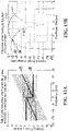
- Figures 13A and13B show similar simulation results for simulation parameters that include 34G baud rate, 0 and 50000 ps/nm accumulative chromatic dispersion, 60MHz pilot tone frequency, where the signal spectrum is divided into two bands.
- the performance or 0 dispersion is shown in curve 1100
- the performance for 50000 ps/nm is shown in curve 1102.
- pre-phase improves the fading with dispersion, but degrades if there is no dispersion.
- the pilot tone applied to each spectral band has a different pilot tone frequency.
- the dispersion fading is 1/N of that of a single band.
- each pilot tone is modulated with a different frequency different pilot tone data (Case A).
- each pilot tone is modulated with a different frequency and the same data (Case B).
- the signal-to-noise ratio (SNR) for the data is relatively higher when each pilot tone is modulated with the same data compared to the case where each pilot tone is modulated with different data.
- a receiver can process a received signal to perform optical performance monitoring. Part of this may, for example, involve optical channel detection. This can be done by detecting the power of pilot tones transmitted for different optical channels.
- pilot tone power detection may be performed in the same way as it would be had the entire band been modulated with a single pilot tone.
- the pilot tones having different frequencies with different data (case A) detection can be performed in each band in the same way as if a single pilot tone was applied to a single large band. An overall result can be obtained by summing the powers in all of the bands.
- the detection results for the multi-band pilot tones are combined to derive the total pilot tone power, and to recover the pilot tone data. In some cases, it may be possible to use one pilot tone to recover the pilot tone data, provided that the SNR is good enough.
- the following is an example of how the multi-band pilot can be applied.
- This approach may be implemented in a DSP, for example.
- ⁇ is the pre-phase applied to mitigate dispersion fading, but a similar approach can be applied to any of bands, and using pilot tones that differ in other manners, for example pilot tone frequency.
- V + ⁇ V ⁇ ⁇ 0
- V ⁇ ⁇ V ⁇ ⁇ 0
- each spectral band is converted back to the time domain:
- V + t iFFT V + ⁇
- V ⁇ t iFFT V ⁇ ⁇
- each band is in the time domain separately with a respective pilot tone, for example, with a pre-phase applied to one of the two bands in this example.
- FIG. 14 is a flowchart of a method of applying pilot tones provided by an embodiment of the invention.
- the method begins at 1400 with spectrally dividing a time domain digital signal into a plurality of spectral bands. However, note that step 1400 is not necessary in the case that the method is to be applied to multiple digital sub-band signals.
- the method continues at 1402 with applying a respective pilot tone to each of at least two of the plurality of spectral bands to produce a respective spectral band with applied pilot tne, the pilot tones differing from each other.
- the method continues at 1404 with recombining the spectral bands with applied pilot tones and any remaining spectral bands that did not have pilot tones applied to produce a recombined time domain digital signal.
- the recombined time domain digital signal is converted to an optical channel signal at 1406. Typically, the optical channel signal would then be transmitted.
- the optical channel signal may be combined with other optical channel signals before transmission.
- Figure 15 is a flowchart of a method of performing optical channel performance monitoring not part of the present invention.
- the method begins at 1500 with receiving an optical channel signal in which different pilot tones have been applied to each of at least two sub-bands.
- the optical channel signal may be part of a signal containing multiple optical channels.
- the method continues at 1502 with performing optical channel performance monitoring based on detecting the pilot tones. Any of the alternatives and modifications described herein can be applied with the method of Figure 15 .
- Figure 16A is a block diagram of an apparatus for applying pilot tones not part of the present invention.
- the apparatus includes a frequency band divider 1600 for spectrally dividing a time domain digital signal into a plurality of spectral bands, and a pilot tone generator 1602 for applying a respective pilot tone to each of at least two of the plurality of spectral bands to produce a respective spectral band with applied pilot tone, the pilot tones differing from each other.
- the frequency band divider 1600 is not necessary for embodiments in which the input is multiple digital sub-band signals.
- the apparatus also includes a spectral band recombiner 1604 for recombining the spectral bands with applied pilot tones and any remaining spectral bands to which pilot tones were not applied to produce a recombined time domain digital signal.
- the apparatus also includes an electrical-to-optical modulator 1606 for converting the recombined time domain digital signal to an optical channel signal for transmission. Any of the alternatives and modifications described herein can be applied with the apparatus of Figure 16A .
- FIG 16B is a block diagram of another apparatus for applying pilot tones provided by an embodiment of the invention.
- the apparatus includes an FFT 1652 converting a time domain digital signal 1650 into a frequency domain signal.
- the frequency domain signal is split into multiple bands 1654,1664. Each band is then converted back to a respective time domain digital signal with a respective IFFT 1656,1666.
- components 1652, 1654, 1656, 1664, 1666 collectively are a specific example of the frequency band divider 1600 of Figure 16A .
- Multipliers 1658,1668 are used to apply respective pilot tone modulations to the two time domain digital signals, and the pilot tone modulated signals are recombined at 1670 prior to digital to analog conversion 1680.
- Figure 17 is a block diagram of an apparatus for performing optical channel performance monitoring not part of the present invention.
- the apparatus includes a receiver 1700 for receiving an optical channel signal in which different pilot tones have been applied to each of at least two sub-bands.
- the apparatus also includes an optical channel performance monitor 1702 for performing optical channel performance monitoring based on detecting the pilot tones. Any of the alternatives and modifications described herein can be applied with the apparatus of Figure 17 .
- the described embodiment make use of a frequency band divider to divide the spectrum of a signal, and following this pilot tone modulation is applied to each spectral band.
- no frequency band divider is provided. Rather, an input to the system and method is multiple different sub-bands that carry different bit streams, from a single source or from multiple individual sources. These different sub-bands are modulated with respective pilot tones, before being combined.
- This approach can be realized from the method of Figure 14 by omitting block 1400, and from the apparatus of Figure 16A by omitting the frequency band divider 1600, and from the apparatus of Figure 16B by omitting the FFT 1652, and treating the two bands 1654 as different sub-band inputs from a single or multiple individual sources.
Landscapes
- Engineering & Computer Science (AREA)
- Signal Processing (AREA)
- Computer Networks & Wireless Communication (AREA)
- Physics & Mathematics (AREA)
- Electromagnetism (AREA)
- Optical Communication System (AREA)
Claims (6)
- Verfahren, umfassend:Anwenden einer FFT auf ein digitales Zeitbereichssignal, um ein Frequenzbereichssignal (1652) zu erzeugen;Aufteilen des Frequenzbereichssignals in eine Vielzahl von Spektralbändern (1654 ~ 1664);Anwenden einer IFFT auf jedes der Vielzahl von Spektralbändern, um entsprechende Wellenformen (1656 ~ 1666) zu erzeugen;für mindestens zwei der Wellenformen Multiplizieren jeder Wellenform mit einem jeweiligen Pilotton, wobei sich die Pilottöne voneinander unterscheiden (1658 ~ 1668);Kombinieren der Wellenformen, an die Pilottöne angelegt sind, und aller verbleibenden Wellenformen, an denen kein Pilotton angelegt ist, um ein kombiniertes digitales Zeitbereichssignal (1670) zu erzeugen; undUmwandeln des kombinierten digitalen Zeitbereichssignals in ein optisches Kanalsignal.
- Verfahren nach Anspruch 1, wobei sich die Pilottöne dadurch voneinander unterscheiden, dass jeder Pilotton eine andere Pilottonfrequenz hat.
- Verfahren nach Anspruch 1, wobei die Pilottöne dieselbe Frequenz haben und sich dadurch voneinander unterscheiden, dass jeder eine andere Vorphase hat.
- Verfahren nach einem der Ansprüche 1 bis 3, ferner umfassend das Ändern mindestens eines der Pilottöne im Laufe der Zeit, wobei das Ändern mindestens eines der Pilottöne im Laufe der Zeit das Ändern mindestens eines der Folgenden umfasst:Modulationstiefe;Pilottonfrequenz;Pilottonphase;eine Anzahl von Pilottönen.
- Gerät, umfassend:einen Pilottonmodulator zum Anwenden einer FFT auf ein digitales Zeitbereichssignal, um ein Frequenzbereichssignal zu erzeugen, Aufteilen des Frequenzbereichssignals in eine Vielzahl von Spektralbändern, Anwenden einer IFFT auf jedes der Vielzahl von Spektralbändern, um jeweilige Wellenformen zu erzeugen, und Multiplizieren jeder Wellenform mit einem entsprechenden Pilotton für mindestens zwei der Wellenformen, wobei sich die Pilottöne voneinander unterscheiden;ein Spektralbandkombinator zum Kombinieren der Wellenformen, an die Pilottöne angelegt sind, und aller verbleibenden Wellenformen, an denen kein Pilotton angelegt ist, um ein kombiniertes digitales Zeitbereichssignal zu erzeugen;einen Elektrisch-zu-Optisch-Modulator zum Umwandeln des kombinierten digitalen Zeitbereichssignals in ein optisches Kanalsignal.
- Gerät nach Anspruch 5, konfiguriert zum Erzeugen von Pilottönen, die sich voneinander dadurch unterscheiden, dass jeder Pilotton eine andere Pilottonfrequenz hat; oder jeder Pilotton eine andere Vorphase hat.
Applications Claiming Priority (2)
| Application Number | Priority Date | Filing Date | Title |
|---|---|---|---|
| US15/479,666 US10523315B2 (en) | 2017-04-05 | 2017-04-05 | Systems and method of multi-band pilot tone based optical performance monitoring |
| PCT/CN2018/079366 WO2018184461A1 (en) | 2017-04-05 | 2018-03-16 | Systems and method of multi-band pilot tone based optical performance monitoring |
Publications (3)
| Publication Number | Publication Date |
|---|---|
| EP3590210A1 EP3590210A1 (de) | 2020-01-08 |
| EP3590210A4 EP3590210A4 (de) | 2020-03-25 |
| EP3590210B1 true EP3590210B1 (de) | 2022-05-25 |
Family
ID=63711285
Family Applications (1)
| Application Number | Title | Priority Date | Filing Date |
|---|---|---|---|
| EP18781482.7A Active EP3590210B1 (de) | 2017-04-05 | 2018-03-16 | Systeme und verfahren zur optischen leistungsüberwachung auf multiband-pilottonbasis |
Country Status (4)
| Country | Link |
|---|---|
| US (1) | US10523315B2 (de) |
| EP (1) | EP3590210B1 (de) |
| CN (1) | CN110463091B (de) |
| WO (1) | WO2018184461A1 (de) |
Families Citing this family (23)
| Publication number | Priority date | Publication date | Assignee | Title |
|---|---|---|---|---|
| CN108781113B (zh) * | 2016-06-24 | 2020-03-20 | 华为技术有限公司 | 用于提供导频音的方法和装置 |
| US10523315B2 (en) | 2017-04-05 | 2019-12-31 | Huawei Technologies Co., Ltd. | Systems and method of multi-band pilot tone based optical performance monitoring |
| US10992389B2 (en) | 2018-02-07 | 2021-04-27 | Infinera Corporation | Independently routable digital subcarriers with configurable spacing for optical communication networks |
| US11368228B2 (en) | 2018-04-13 | 2022-06-21 | Infinera Corporation | Apparatuses and methods for digital subcarrier parameter modifications for optical communication networks |
| US11095389B2 (en) | 2018-07-12 | 2021-08-17 | Infiriera Corporation | Subcarrier based data center network architecture |
| US10979167B2 (en) | 2018-10-01 | 2021-04-13 | Huawei Technologies Co., Ltd. | Systems and method of multi-laser wavelength control |
| US11095364B2 (en) | 2019-03-04 | 2021-08-17 | Infiriera Corporation | Frequency division multiple access optical subcarriers |
| US11258528B2 (en) | 2019-09-22 | 2022-02-22 | Infinera Corporation | Frequency division multiple access optical subcarriers |
| US11336369B2 (en) | 2019-03-22 | 2022-05-17 | Infinera Corporation | Framework for handling signal integrity using ASE in optical networks |
| US10965439B2 (en) | 2019-04-19 | 2021-03-30 | Infinera Corporation | Synchronization for subcarrier communication |
| US10972184B2 (en) | 2019-05-07 | 2021-04-06 | Infinera Corporation | Bidirectional optical communications |
| US11095374B2 (en) * | 2019-05-14 | 2021-08-17 | Infinera Corporation | Out-of-band communication channel for sub-carrier-based optical communication systems |
| US11190291B2 (en) | 2019-05-14 | 2021-11-30 | Infinera Corporation | Out-of-band communication channel for subcarrier-based optical communication systems |
| US11489613B2 (en) | 2019-05-14 | 2022-11-01 | Infinera Corporation | Out-of-band communication channel for subcarrier-based optical communication systems |
| US11476966B2 (en) | 2019-05-14 | 2022-10-18 | Infinera Corporation | Out-of-band communication channel for subcarrier-based optical communication systems |
| US11239935B2 (en) * | 2019-05-14 | 2022-02-01 | Infinera Corporation | Out-of-band communication channel for subcarrier-based optical communication systems |
| US11296812B2 (en) | 2019-05-14 | 2022-04-05 | Infinera Corporation | Out-of-band communication channel for subcarrier-based optical communication systems |
| US11297005B2 (en) | 2019-09-05 | 2022-04-05 | Infiriera Corporation | Dynamically switching queueing schemes for network switches |
| EP4042606A1 (de) | 2019-10-10 | 2022-08-17 | Infinera Corporation | Optischer unterträger-zweiwegschutz und wiederherstellung für optische kommunikationsnetzwerke |
| US11743621B2 (en) | 2019-10-10 | 2023-08-29 | Infinera Corporation | Network switches systems for optical communications networks |
| US12081269B2 (en) | 2019-10-10 | 2024-09-03 | Infinera Corporation | Hub-leaf laser synchronization |
| CN114221700B (zh) * | 2021-12-22 | 2023-06-13 | 阿里巴巴(中国)有限公司 | 计算光传输网络的配置的方法、装置及光传输网络系统 |
| CN120200664A (zh) * | 2023-12-22 | 2025-06-24 | 华为技术有限公司 | 一种光检测设备、光发射机、检测方法及通信方法 |
Family Cites Families (64)
| Publication number | Priority date | Publication date | Assignee | Title |
|---|---|---|---|---|
| US6046838A (en) | 1998-12-22 | 2000-04-04 | Kestrel Solutions, Inc. | Automatic bias control for electro-optic modulators |
| GB9907496D0 (en) | 1999-03-31 | 1999-05-26 | British Telecomm | Communications network |
| KR100301950B1 (ko) * | 1999-04-02 | 2001-10-29 | 윤덕용 | 광 회선분배 시스템의 입력단자 판별에 의한 광 경로 감시 장치 |
| US6614776B1 (en) | 1999-04-28 | 2003-09-02 | Tantivy Communications, Inc. | Forward error correction scheme for high rate data exchange in a wireless system |
| WO2001026256A1 (en) | 1999-09-02 | 2001-04-12 | Ortel Corporation | Composite second-order bias control schemes |
| US7197243B1 (en) * | 2000-03-31 | 2007-03-27 | Nortel Networks Limited | Optical waveform for use in a DWDM optical network and systems for generating and processing same |
| JP2002228550A (ja) | 2001-02-02 | 2002-08-14 | Ando Electric Co Ltd | 波長分散分布測定器、及び測定方法 |
| KR100408187B1 (ko) | 2001-04-24 | 2003-12-03 | 한국과학기술원 | 주파수 변조된 광신호 전송장치 및 주파수 변조된광신호의 전력 및 광주파수 감시장치 |
| JP3880437B2 (ja) | 2001-08-31 | 2007-02-14 | 松下電器産業株式会社 | 送受信装置及び送受信方法 |
| CA2358382C (en) | 2001-10-05 | 2008-09-09 | Ping Wai Wan | Channel identification in communications networks |
| GB2383706B (en) * | 2001-11-30 | 2005-03-30 | Marconi Optical Components Ltd | Modulation control |
| US7346279B1 (en) * | 2002-03-25 | 2008-03-18 | Forster Energy Llc | Optical transceiver using heterodyne detection and a transmitted reference clock |
| US7007223B2 (en) | 2002-06-30 | 2006-02-28 | Intel Corporation | Efficient method and apparatus for low latency forward error correction |
| JP2004040668A (ja) * | 2002-07-05 | 2004-02-05 | Nec Corp | 光信号伝送システム及び方法、光信号送信装置及び方法、並びに光信号受信装置及び方法 |
| JP3883919B2 (ja) * | 2002-07-16 | 2007-02-21 | 富士通株式会社 | 状態検出機能を備えた光送信装置 |
| KR20040035291A (ko) | 2002-10-19 | 2004-04-29 | 삼성전자주식회사 | 주파수영역에 파일럿 톤을 삽입한 다중 반송파 송신시스템 및 그의 파일럿 삽입방법 |
| DE60304436T2 (de) | 2003-01-14 | 2006-08-24 | Agilent Technologies, Inc. (n.d.Ges.d.Staates Delaware), Palo Alto | Verfahren und Gerät zum Einkoppeln eines Pilottons in ein Digitalsignal |
| US7412166B2 (en) * | 2003-04-30 | 2008-08-12 | Tellabs Operations, Inc. | Pilot tones for optical signal wavelength identification and power measurement |
| CN1581756A (zh) * | 2003-08-06 | 2005-02-16 | 华为技术有限公司 | 光调顶传输方法和系统 |
| JP2005148329A (ja) * | 2003-11-14 | 2005-06-09 | Fujitsu Ltd | 光変調装置 |
| US7539187B2 (en) | 2004-07-07 | 2009-05-26 | Qvidium Technologies, Inc. | System and method for low-latency content-sensitive forward error correction |
| US7630126B2 (en) | 2005-02-28 | 2009-12-08 | Alcatel-Lucent Usa Inc. | Two-pump optical parametric devices having reduced stimulated Raman scattering noise levels |
| AU2006330069A1 (en) | 2005-06-13 | 2007-07-05 | Ccor Solutions | Four quadrant linearizer |
| KR100772504B1 (ko) * | 2005-12-01 | 2007-11-01 | 한국전자통신연구원 | 높은 전송 전력 효율을 가지는 ofdm 세기 변조 /직접검파방식의 유/무선 통신 시스템 변조/복조 장치와 방법 |
| US7783193B2 (en) | 2006-05-30 | 2010-08-24 | Alcatel Lucent | Noise tone avoidance in optical networks |
| JP5130702B2 (ja) * | 2006-12-05 | 2013-01-30 | 富士通株式会社 | 偏波直交制御装置 |
| US8032022B2 (en) | 2008-02-06 | 2011-10-04 | At&T Intellectual Property Ii, L.P. | Method for lightpath monitoring in an optical routing network |
| US20090324226A1 (en) * | 2008-06-30 | 2009-12-31 | Fred Buchali | System, method and apparatus for channel estimation based on intra-symbol frequency domain averaging for coherent optical OFDM |
| US20090324223A1 (en) * | 2008-06-30 | 2009-12-31 | Xiang Liu | System, method and apparatus for channel estimation with dual polarization training symbols for coherent optical OFDM |
| US9264134B2 (en) * | 2008-09-29 | 2016-02-16 | Infinera Corporation | Automatic laser shutdown and recovery in response to a link break |
| US8204377B2 (en) * | 2008-10-23 | 2012-06-19 | Alcatel Lucent | System, method and apparatus for joint self phase modulation compensation for coherent optical polarization-division-multiplexed orthogonal-frequency division-multiplexing systems |
| US20100150577A1 (en) * | 2008-12-16 | 2010-06-17 | Essiambre Rene-Jean | Communication System and Method With Signal Constellation |
| US8218979B2 (en) * | 2009-06-30 | 2012-07-10 | Alcatel Lucent | System, method and apparatus for coherent optical OFDM |
| WO2011106626A2 (en) * | 2010-02-25 | 2011-09-01 | Interdigital Patent Holdings, Inc. | Blind timing synchronization and low complexity channel estimation in aco-ofdm systems |
| US20110228838A1 (en) | 2010-03-17 | 2011-09-22 | Trendchip Technologies Corp. | Apparatus for impulse noise mitigation |
| GB2480311A (en) * | 2010-05-13 | 2011-11-16 | Univ Bangor | Optical OFDM synchronisation using clock signal transmitted outside OFDM symbol frequency band |
| KR20120068337A (ko) * | 2010-12-17 | 2012-06-27 | 한국전자통신연구원 | 코히어런트 광 ofdm 송수신 방법 및 장치 |
| US20120170929A1 (en) * | 2011-01-03 | 2012-07-05 | Chongjin Xie | Apparatus And Method For Monitoring An Optical Coherent Network |
| GB2489922A (en) * | 2011-04-06 | 2012-10-17 | Univ Bangor | Synchronising optical OFDM signal with pattern of DC offset levels superimposed upon OFDM symbols |
| EP2642676B1 (de) * | 2012-03-20 | 2017-03-15 | ADVA Optical Networking SE | Verfahren und Einrichtung zum Betrieb eines optischen Übertragungssystems |
| US8923457B2 (en) * | 2012-04-02 | 2014-12-30 | Nec Laboratories America, Inc. | Method and system for pilot-based time domain phase noise mitigation for coherent receiver |
| JP5962414B2 (ja) * | 2012-10-10 | 2016-08-03 | 富士通株式会社 | 光伝送システム、光伝送装置の調整方法、および光伝送装置の調整プログラム |
| US8971719B2 (en) * | 2012-12-21 | 2015-03-03 | Infinera Corporation | Nonlinearity compensation using pilot tones |
| US9479260B2 (en) * | 2013-05-03 | 2016-10-25 | Futurewei Technologies, Inc. | Single carrier flexible bit rate transceiver for coherent optical network |
| WO2015096094A1 (zh) * | 2013-12-26 | 2015-07-02 | 华为技术有限公司 | 信号的调制及数字信息的恢复方法、通信设备及系统 |
| US9363583B2 (en) | 2013-12-27 | 2016-06-07 | Futurewei Technologies, Inc. | System and method for reducing the stimulated Raman scattering crosstalk in channel monitoring |
| US9270370B2 (en) * | 2014-01-29 | 2016-02-23 | Huawei Technologies Co., Ltd. | System and method for pilot tone modulation by data bias |
| GB201406271D0 (en) * | 2014-04-08 | 2014-05-21 | Univ Aston | Method of Non-Linearity Compensation in Optical Fibre Communications |
| CN106464631B (zh) * | 2014-06-13 | 2019-10-25 | 华为技术有限公司 | 正交频分复用光信号的调制方法、装置及设备 |
| US9749056B2 (en) * | 2015-01-14 | 2017-08-29 | Huawei Technologies Co., Ltd | Method and system for discrete multi-tone transmission with multiple modulations |
| CN106161329B (zh) * | 2015-04-24 | 2019-07-30 | 富士通株式会社 | 信号处理装置、信号发送装置以及接收机 |
| US9780888B2 (en) * | 2015-05-12 | 2017-10-03 | Qualcomm Incorporated | Techniques for mitigating cross device co-existence interference |
| US9614638B2 (en) | 2015-07-02 | 2017-04-04 | Fujitsu Limited | Methods and systems for periodic optical filtering to identify tone modulated optical signals |
| US9647767B2 (en) * | 2015-08-20 | 2017-05-09 | Futurewei Technologies, Inc. | Estimation and compensation of local oscillator frequency offset and chromatic dispersion using pilot tones in spectral-shaping subcarrier modulation |
| US10003426B2 (en) * | 2016-02-19 | 2018-06-19 | Huawei Technologies Co., Ltd. | Wavelength conflict detection using coded pilot tone |
| CN108702208B (zh) | 2016-02-19 | 2020-07-24 | 华为技术有限公司 | 利用扩频导频音的光信道监测 |
| US9941960B2 (en) * | 2016-06-22 | 2018-04-10 | Huawei Technologies Co., Ltd. | Method and system for optical performance monitoring |
| US20170255078A1 (en) | 2016-03-03 | 2017-09-07 | Huawei Technologies Co., Ltd. | Wavelength selective switch with monitoring ports |
| US9705592B1 (en) * | 2016-04-05 | 2017-07-11 | Infinera Corporation | In-service skew monitoring in a nested Mach-Zehnder modulator structure using pilot signals and balanced phase detection |
| CN108781113B (zh) * | 2016-06-24 | 2020-03-20 | 华为技术有限公司 | 用于提供导频音的方法和装置 |
| US10038546B2 (en) * | 2016-10-20 | 2018-07-31 | Nokia Of America Corporation | Method and apparatus for locking WDM transmitter carriers to a defined grid |
| US10027424B2 (en) * | 2016-11-22 | 2018-07-17 | Ciena Corporation | Low-latency adjustment of flexible transceivers using pilot signal |
| US10523315B2 (en) | 2017-04-05 | 2019-12-31 | Huawei Technologies Co., Ltd. | Systems and method of multi-band pilot tone based optical performance monitoring |
| US10574351B2 (en) | 2017-10-23 | 2020-02-25 | Huawei Technologies Co., Ltd. | Monitoring performance of optical network equipment using pilot tones |
-
2017
- 2017-04-05 US US15/479,666 patent/US10523315B2/en active Active
-
2018
- 2018-03-16 CN CN201880017278.6A patent/CN110463091B/zh active Active
- 2018-03-16 WO PCT/CN2018/079366 patent/WO2018184461A1/en not_active Ceased
- 2018-03-16 EP EP18781482.7A patent/EP3590210B1/de active Active
Also Published As
| Publication number | Publication date |
|---|---|
| US10523315B2 (en) | 2019-12-31 |
| CN110463091A (zh) | 2019-11-15 |
| EP3590210A1 (de) | 2020-01-08 |
| EP3590210A4 (de) | 2020-03-25 |
| US20180294874A1 (en) | 2018-10-11 |
| WO2018184461A1 (en) | 2018-10-11 |
| CN110463091B (zh) | 2021-02-23 |
Similar Documents
| Publication | Publication Date | Title |
|---|---|---|
| EP3590210B1 (de) | Systeme und verfahren zur optischen leistungsüberwachung auf multiband-pilottonbasis | |
| US10574351B2 (en) | Monitoring performance of optical network equipment using pilot tones | |
| US8655170B2 (en) | OSNR monitor device and OSNR measurement device | |
| CN103326777B (zh) | 光功率监测器、光功率控制系统和光功率监测方法 | |
| JP6829766B2 (ja) | 光送信機、光受信機及び光伝送システム | |
| US20120219285A1 (en) | In-band optical signal to noise ratio monitoring technique | |
| US9294216B2 (en) | Optical OFDM transmission | |
| JP2003510890A (ja) | Nrzwdmシステムのfwm損失を減じる方法とそのシステム | |
| US10469163B2 (en) | Optical channel monitoring using expanded-spectrum pilot tone | |
| JP2015091131A (ja) | 偏波依存損失を監視するシステム及び方法 | |
| EP3058670B1 (de) | System und verfahren mit spektralformung und expandiertem kanalabstand | |
| US7912370B2 (en) | Optical power measurement apparatus and optical power measurement method | |
| JP2015106829A (ja) | 光信号品質モニタ装置、光伝送装置、及び、光信号品質モニタ方法 | |
| EP2975788A2 (de) | Optische übertragungsvorrichtung und detektionsvorrichtung | |
| US11575556B2 (en) | Estimation of communication system impairments using spectrally selective signal perturbations | |
| WO2011083798A1 (ja) | 波長分散を検出する方法及び装置並びに波長分散を補償する方法及び装置 | |
| EP3844896B1 (de) | Überwachung der leistung eines optischen netzwerks mit niedrigleistungslücken und einem pilotton | |
| JP2017011471A (ja) | 光分岐挿入装置 | |
| US10256907B2 (en) | System and method for coherent detection with digital signal procession | |
| EP3417552B1 (de) | Verfahren und vorrichtung zur bereitstellung eines pilottons | |
| EP3923488B1 (de) | Erzeugen eines pilottons für ein optisches telekommunikationssystem | |
| EP3754868A1 (de) | Volloptischer intrakanal-multiwellenlängen-linear-zu-nichtlinearer leistungsverhältnismonitor | |
| JP6422799B2 (ja) | 光伝送システム、光送信装置及びその制御方法 | |
| Hong et al. | Modulation format identification and transmission quality monitoring for link establishment in optical network using machine learning techniques | |
| CN117768027A (zh) | 一种光信号调制和监测方法及相关装置 |
Legal Events
| Date | Code | Title | Description |
|---|---|---|---|
| STAA | Information on the status of an ep patent application or granted ep patent |
Free format text: STATUS: THE INTERNATIONAL PUBLICATION HAS BEEN MADE |
|
| PUAI | Public reference made under article 153(3) epc to a published international application that has entered the european phase |
Free format text: ORIGINAL CODE: 0009012 |
|
| STAA | Information on the status of an ep patent application or granted ep patent |
Free format text: STATUS: REQUEST FOR EXAMINATION WAS MADE |
|
| 17P | Request for examination filed |
Effective date: 20191001 |
|
| AK | Designated contracting states |
Kind code of ref document: A1 Designated state(s): AL AT BE BG CH CY CZ DE DK EE ES FI FR GB GR HR HU IE IS IT LI LT LU LV MC MK MT NL NO PL PT RO RS SE SI SK SM TR |
|
| AX | Request for extension of the european patent |
Extension state: BA ME |
|
| REG | Reference to a national code |
Ref country code: DE Ref legal event code: R079 Ref document number: 602018036012 Country of ref document: DE Free format text: PREVIOUS MAIN CLASS: H04J0014020000 Ipc: H04B0010077000 |
|
| A4 | Supplementary search report drawn up and despatched |
Effective date: 20200221 |
|
| RIC1 | Information provided on ipc code assigned before grant |
Ipc: H04B 10/077 20130101AFI20200217BHEP Ipc: H04L 5/00 20060101ALI20200217BHEP |
|
| DAV | Request for validation of the european patent (deleted) | ||
| DAX | Request for extension of the european patent (deleted) | ||
| GRAP | Despatch of communication of intention to grant a patent |
Free format text: ORIGINAL CODE: EPIDOSNIGR1 |
|
| STAA | Information on the status of an ep patent application or granted ep patent |
Free format text: STATUS: GRANT OF PATENT IS INTENDED |
|
| INTG | Intention to grant announced |
Effective date: 20220105 |
|
| GRAS | Grant fee paid |
Free format text: ORIGINAL CODE: EPIDOSNIGR3 |
|
| GRAA | (expected) grant |
Free format text: ORIGINAL CODE: 0009210 |
|
| STAA | Information on the status of an ep patent application or granted ep patent |
Free format text: STATUS: THE PATENT HAS BEEN GRANTED |
|
| AK | Designated contracting states |
Kind code of ref document: B1 Designated state(s): AL AT BE BG CH CY CZ DE DK EE ES FI FR GB GR HR HU IE IS IT LI LT LU LV MC MK MT NL NO PL PT RO RS SE SI SK SM TR |
|
| REG | Reference to a national code |
Ref country code: GB Ref legal event code: FG4D |
|
| REG | Reference to a national code |
Ref country code: CH Ref legal event code: EP |
|
| REG | Reference to a national code |
Ref country code: AT Ref legal event code: REF Ref document number: 1494664 Country of ref document: AT Kind code of ref document: T Effective date: 20220615 Ref country code: DE Ref legal event code: R096 Ref document number: 602018036012 Country of ref document: DE |
|
| REG | Reference to a national code |
Ref country code: IE Ref legal event code: FG4D |
|
| REG | Reference to a national code |
Ref country code: LT Ref legal event code: MG9D |
|
| REG | Reference to a national code |
Ref country code: NL Ref legal event code: MP Effective date: 20220525 |
|
| REG | Reference to a national code |
Ref country code: AT Ref legal event code: MK05 Ref document number: 1494664 Country of ref document: AT Kind code of ref document: T Effective date: 20220525 |
|
| PG25 | Lapsed in a contracting state [announced via postgrant information from national office to epo] |
Ref country code: SE Free format text: LAPSE BECAUSE OF FAILURE TO SUBMIT A TRANSLATION OF THE DESCRIPTION OR TO PAY THE FEE WITHIN THE PRESCRIBED TIME-LIMIT Effective date: 20220525 Ref country code: PT Free format text: LAPSE BECAUSE OF FAILURE TO SUBMIT A TRANSLATION OF THE DESCRIPTION OR TO PAY THE FEE WITHIN THE PRESCRIBED TIME-LIMIT Effective date: 20220926 Ref country code: NO Free format text: LAPSE BECAUSE OF FAILURE TO SUBMIT A TRANSLATION OF THE DESCRIPTION OR TO PAY THE FEE WITHIN THE PRESCRIBED TIME-LIMIT Effective date: 20220825 Ref country code: NL Free format text: LAPSE BECAUSE OF FAILURE TO SUBMIT A TRANSLATION OF THE DESCRIPTION OR TO PAY THE FEE WITHIN THE PRESCRIBED TIME-LIMIT Effective date: 20220525 Ref country code: LT Free format text: LAPSE BECAUSE OF FAILURE TO SUBMIT A TRANSLATION OF THE DESCRIPTION OR TO PAY THE FEE WITHIN THE PRESCRIBED TIME-LIMIT Effective date: 20220525 Ref country code: HR Free format text: LAPSE BECAUSE OF FAILURE TO SUBMIT A TRANSLATION OF THE DESCRIPTION OR TO PAY THE FEE WITHIN THE PRESCRIBED TIME-LIMIT Effective date: 20220525 Ref country code: GR Free format text: LAPSE BECAUSE OF FAILURE TO SUBMIT A TRANSLATION OF THE DESCRIPTION OR TO PAY THE FEE WITHIN THE PRESCRIBED TIME-LIMIT Effective date: 20220826 Ref country code: FI Free format text: LAPSE BECAUSE OF FAILURE TO SUBMIT A TRANSLATION OF THE DESCRIPTION OR TO PAY THE FEE WITHIN THE PRESCRIBED TIME-LIMIT Effective date: 20220525 Ref country code: ES Free format text: LAPSE BECAUSE OF FAILURE TO SUBMIT A TRANSLATION OF THE DESCRIPTION OR TO PAY THE FEE WITHIN THE PRESCRIBED TIME-LIMIT Effective date: 20220525 Ref country code: BG Free format text: LAPSE BECAUSE OF FAILURE TO SUBMIT A TRANSLATION OF THE DESCRIPTION OR TO PAY THE FEE WITHIN THE PRESCRIBED TIME-LIMIT Effective date: 20220825 Ref country code: AT Free format text: LAPSE BECAUSE OF FAILURE TO SUBMIT A TRANSLATION OF THE DESCRIPTION OR TO PAY THE FEE WITHIN THE PRESCRIBED TIME-LIMIT Effective date: 20220525 |
|
| PG25 | Lapsed in a contracting state [announced via postgrant information from national office to epo] |
Ref country code: RS Free format text: LAPSE BECAUSE OF FAILURE TO SUBMIT A TRANSLATION OF THE DESCRIPTION OR TO PAY THE FEE WITHIN THE PRESCRIBED TIME-LIMIT Effective date: 20220525 Ref country code: PL Free format text: LAPSE BECAUSE OF FAILURE TO SUBMIT A TRANSLATION OF THE DESCRIPTION OR TO PAY THE FEE WITHIN THE PRESCRIBED TIME-LIMIT Effective date: 20220525 Ref country code: LV Free format text: LAPSE BECAUSE OF FAILURE TO SUBMIT A TRANSLATION OF THE DESCRIPTION OR TO PAY THE FEE WITHIN THE PRESCRIBED TIME-LIMIT Effective date: 20220525 Ref country code: IS Free format text: LAPSE BECAUSE OF FAILURE TO SUBMIT A TRANSLATION OF THE DESCRIPTION OR TO PAY THE FEE WITHIN THE PRESCRIBED TIME-LIMIT Effective date: 20220925 |
|
| PG25 | Lapsed in a contracting state [announced via postgrant information from national office to epo] |
Ref country code: SM Free format text: LAPSE BECAUSE OF FAILURE TO SUBMIT A TRANSLATION OF THE DESCRIPTION OR TO PAY THE FEE WITHIN THE PRESCRIBED TIME-LIMIT Effective date: 20220525 Ref country code: SK Free format text: LAPSE BECAUSE OF FAILURE TO SUBMIT A TRANSLATION OF THE DESCRIPTION OR TO PAY THE FEE WITHIN THE PRESCRIBED TIME-LIMIT Effective date: 20220525 Ref country code: RO Free format text: LAPSE BECAUSE OF FAILURE TO SUBMIT A TRANSLATION OF THE DESCRIPTION OR TO PAY THE FEE WITHIN THE PRESCRIBED TIME-LIMIT Effective date: 20220525 Ref country code: EE Free format text: LAPSE BECAUSE OF FAILURE TO SUBMIT A TRANSLATION OF THE DESCRIPTION OR TO PAY THE FEE WITHIN THE PRESCRIBED TIME-LIMIT Effective date: 20220525 Ref country code: DK Free format text: LAPSE BECAUSE OF FAILURE TO SUBMIT A TRANSLATION OF THE DESCRIPTION OR TO PAY THE FEE WITHIN THE PRESCRIBED TIME-LIMIT Effective date: 20220525 Ref country code: CZ Free format text: LAPSE BECAUSE OF FAILURE TO SUBMIT A TRANSLATION OF THE DESCRIPTION OR TO PAY THE FEE WITHIN THE PRESCRIBED TIME-LIMIT Effective date: 20220525 |
|
| REG | Reference to a national code |
Ref country code: DE Ref legal event code: R097 Ref document number: 602018036012 Country of ref document: DE |
|
| PG25 | Lapsed in a contracting state [announced via postgrant information from national office to epo] |
Ref country code: AL Free format text: LAPSE BECAUSE OF FAILURE TO SUBMIT A TRANSLATION OF THE DESCRIPTION OR TO PAY THE FEE WITHIN THE PRESCRIBED TIME-LIMIT Effective date: 20220525 |
|
| PLBE | No opposition filed within time limit |
Free format text: ORIGINAL CODE: 0009261 |
|
| STAA | Information on the status of an ep patent application or granted ep patent |
Free format text: STATUS: NO OPPOSITION FILED WITHIN TIME LIMIT |
|
| 26N | No opposition filed |
Effective date: 20230228 |
|
| PG25 | Lapsed in a contracting state [announced via postgrant information from national office to epo] |
Ref country code: SI Free format text: LAPSE BECAUSE OF FAILURE TO SUBMIT A TRANSLATION OF THE DESCRIPTION OR TO PAY THE FEE WITHIN THE PRESCRIBED TIME-LIMIT Effective date: 20220525 |
|
| P01 | Opt-out of the competence of the unified patent court (upc) registered |
Effective date: 20230524 |
|
| PG25 | Lapsed in a contracting state [announced via postgrant information from national office to epo] |
Ref country code: MC Free format text: LAPSE BECAUSE OF FAILURE TO SUBMIT A TRANSLATION OF THE DESCRIPTION OR TO PAY THE FEE WITHIN THE PRESCRIBED TIME-LIMIT Effective date: 20220525 |
|
| REG | Reference to a national code |
Ref country code: CH Ref legal event code: PL |
|
| GBPC | Gb: european patent ceased through non-payment of renewal fee |
Effective date: 20230316 |
|
| REG | Reference to a national code |
Ref country code: BE Ref legal event code: MM Effective date: 20230331 |
|
| PG25 | Lapsed in a contracting state [announced via postgrant information from national office to epo] |
Ref country code: LU Free format text: LAPSE BECAUSE OF NON-PAYMENT OF DUE FEES Effective date: 20230316 |
|
| REG | Reference to a national code |
Ref country code: IE Ref legal event code: MM4A |
|
| PG25 | Lapsed in a contracting state [announced via postgrant information from national office to epo] |
Ref country code: GB Free format text: LAPSE BECAUSE OF NON-PAYMENT OF DUE FEES Effective date: 20230316 |
|
| PG25 | Lapsed in a contracting state [announced via postgrant information from national office to epo] |
Ref country code: LI Free format text: LAPSE BECAUSE OF NON-PAYMENT OF DUE FEES Effective date: 20230331 Ref country code: IT Free format text: LAPSE BECAUSE OF FAILURE TO SUBMIT A TRANSLATION OF THE DESCRIPTION OR TO PAY THE FEE WITHIN THE PRESCRIBED TIME-LIMIT Effective date: 20220525 Ref country code: IE Free format text: LAPSE BECAUSE OF NON-PAYMENT OF DUE FEES Effective date: 20230316 Ref country code: GB Free format text: LAPSE BECAUSE OF NON-PAYMENT OF DUE FEES Effective date: 20230316 Ref country code: FR Free format text: LAPSE BECAUSE OF NON-PAYMENT OF DUE FEES Effective date: 20230331 Ref country code: CH Free format text: LAPSE BECAUSE OF NON-PAYMENT OF DUE FEES Effective date: 20230331 |
|
| PG25 | Lapsed in a contracting state [announced via postgrant information from national office to epo] |
Ref country code: BE Free format text: LAPSE BECAUSE OF NON-PAYMENT OF DUE FEES Effective date: 20230331 |
|
| PG25 | Lapsed in a contracting state [announced via postgrant information from national office to epo] |
Ref country code: BG Free format text: LAPSE BECAUSE OF FAILURE TO SUBMIT A TRANSLATION OF THE DESCRIPTION OR TO PAY THE FEE WITHIN THE PRESCRIBED TIME-LIMIT Effective date: 20220525 |
|
| PG25 | Lapsed in a contracting state [announced via postgrant information from national office to epo] |
Ref country code: BG Free format text: LAPSE BECAUSE OF FAILURE TO SUBMIT A TRANSLATION OF THE DESCRIPTION OR TO PAY THE FEE WITHIN THE PRESCRIBED TIME-LIMIT Effective date: 20220525 |
|
| PGFP | Annual fee paid to national office [announced via postgrant information from national office to epo] |
Ref country code: DE Payment date: 20250204 Year of fee payment: 8 |
|
| PG25 | Lapsed in a contracting state [announced via postgrant information from national office to epo] |
Ref country code: CY Free format text: LAPSE BECAUSE OF FAILURE TO SUBMIT A TRANSLATION OF THE DESCRIPTION OR TO PAY THE FEE WITHIN THE PRESCRIBED TIME-LIMIT; INVALID AB INITIO Effective date: 20180316 |
|
| PG25 | Lapsed in a contracting state [announced via postgrant information from national office to epo] |
Ref country code: HU Free format text: LAPSE BECAUSE OF FAILURE TO SUBMIT A TRANSLATION OF THE DESCRIPTION OR TO PAY THE FEE WITHIN THE PRESCRIBED TIME-LIMIT; INVALID AB INITIO Effective date: 20180316 |
|
| PG25 | Lapsed in a contracting state [announced via postgrant information from national office to epo] |
Ref country code: TR Free format text: LAPSE BECAUSE OF FAILURE TO SUBMIT A TRANSLATION OF THE DESCRIPTION OR TO PAY THE FEE WITHIN THE PRESCRIBED TIME-LIMIT Effective date: 20220525 |