EP3590182B1 - Couplage magnétique et procédé - Google Patents
Couplage magnétique et procédé Download PDFInfo
- Publication number
- EP3590182B1 EP3590182B1 EP18715061.0A EP18715061A EP3590182B1 EP 3590182 B1 EP3590182 B1 EP 3590182B1 EP 18715061 A EP18715061 A EP 18715061A EP 3590182 B1 EP3590182 B1 EP 3590182B1
- Authority
- EP
- European Patent Office
- Prior art keywords
- magnets
- driving member
- magnet
- driven member
- driven
- Prior art date
- Legal status (The legal status is an assumption and is not a legal conclusion. Google has not performed a legal analysis and makes no representation as to the accuracy of the status listed.)
- Active
Links
- 230000008878 coupling Effects 0.000 title claims description 14
- 238000010168 coupling process Methods 0.000 title claims description 14
- 238000005859 coupling reaction Methods 0.000 title claims description 14
- 238000000034 method Methods 0.000 title claims description 12
- 238000013459 approach Methods 0.000 claims description 9
- 238000004519 manufacturing process Methods 0.000 claims 1
- 230000005540 biological transmission Effects 0.000 description 12
- 238000000926 separation method Methods 0.000 description 10
- 230000033001 locomotion Effects 0.000 description 7
- BGPVFRJUHWVFKM-UHFFFAOYSA-N N1=C2C=CC=CC2=[N+]([O-])C1(CC1)CCC21N=C1C=CC=CC1=[N+]2[O-] Chemical compound N1=C2C=CC=CC2=[N+]([O-])C1(CC1)CCC21N=C1C=CC=CC1=[N+]2[O-] BGPVFRJUHWVFKM-UHFFFAOYSA-N 0.000 description 4
- 238000005381 potential energy Methods 0.000 description 4
- 230000008901 benefit Effects 0.000 description 3
- 238000006243 chemical reaction Methods 0.000 description 3
- 230000001965 increasing effect Effects 0.000 description 3
- 230000003993 interaction Effects 0.000 description 3
- 230000004888 barrier function Effects 0.000 description 2
- 230000008859 change Effects 0.000 description 2
- 239000000314 lubricant Substances 0.000 description 2
- 239000000463 material Substances 0.000 description 2
- 238000010248 power generation Methods 0.000 description 2
- 239000007787 solid Substances 0.000 description 2
- 229910000831 Steel Inorganic materials 0.000 description 1
- 230000001133 acceleration Effects 0.000 description 1
- 238000011109 contamination Methods 0.000 description 1
- 230000007423 decrease Effects 0.000 description 1
- 230000001419 dependent effect Effects 0.000 description 1
- 230000005611 electricity Effects 0.000 description 1
- 230000005484 gravity Effects 0.000 description 1
- 230000001939 inductive effect Effects 0.000 description 1
- 238000005461 lubrication Methods 0.000 description 1
- 239000000696 magnetic material Substances 0.000 description 1
- 230000005389 magnetism Effects 0.000 description 1
- 230000007246 mechanism Effects 0.000 description 1
- 230000035699 permeability Effects 0.000 description 1
- 229910052761 rare earth metal Inorganic materials 0.000 description 1
- 230000009467 reduction Effects 0.000 description 1
- 125000006850 spacer group Chemical group 0.000 description 1
- 239000010959 steel Substances 0.000 description 1
Images


Classifications
-
- H—ELECTRICITY
- H02—GENERATION; CONVERSION OR DISTRIBUTION OF ELECTRIC POWER
- H02K—DYNAMO-ELECTRIC MACHINES
- H02K49/00—Dynamo-electric clutches; Dynamo-electric brakes
- H02K49/10—Dynamo-electric clutches; Dynamo-electric brakes of the permanent-magnet type
- H02K49/102—Magnetic gearings, i.e. assembly of gears, linear or rotary, by which motion is magnetically transferred without physical contact
-
- H—ELECTRICITY
- H02—GENERATION; CONVERSION OR DISTRIBUTION OF ELECTRIC POWER
- H02K—DYNAMO-ELECTRIC MACHINES
- H02K49/00—Dynamo-electric clutches; Dynamo-electric brakes
- H02K49/10—Dynamo-electric clutches; Dynamo-electric brakes of the permanent-magnet type
- H02K49/104—Magnetic couplings consisting of only two coaxial rotary elements, i.e. the driving element and the driven element
-
- H—ELECTRICITY
- H02—GENERATION; CONVERSION OR DISTRIBUTION OF ELECTRIC POWER
- H02K—DYNAMO-ELECTRIC MACHINES
- H02K51/00—Dynamo-electric gears, i.e. dynamo-electric means for transmitting mechanical power from a driving shaft to a driven shaft and comprising structurally interrelated motor and generator parts
-
- H—ELECTRICITY
- H02—GENERATION; CONVERSION OR DISTRIBUTION OF ELECTRIC POWER
- H02K—DYNAMO-ELECTRIC MACHINES
- H02K7/00—Arrangements for handling mechanical energy structurally associated with dynamo-electric machines, e.g. structural association with mechanical driving motors or auxiliary dynamo-electric machines
- H02K7/18—Structural association of electric generators with mechanical driving motors, e.g. with turbines
- H02K7/1807—Rotary generators
Definitions
- Document JP 2005253292 A describes a permanent magnet (or electromagnet) that is disposed on the side faces of paired gears made of steel having a high magnetic permeability si that N-poles (or S-poles) are opposed to each other. A magnetic repulsive force is generated between the tooth surfaces that engage, which can result in a reduction in contact surface pressure or a non-contact state.
- Document FR 2546253 A1 describes a device for magnetic coupling between two rotary driving and driven shafts, comprising two neighbouring transverse discs respectively fastened to the two driving and driven shafts and each carrying, at their periphery, a succession of magnets.
- This device is characterised in that the driving shaft and driven shaft are parallel to one another and spaced apart by a distance which is less than the sum of the radii of the two.
- Document DE 102009056227 A1 describes a wheel with a set of teeth comprising a magnetic polarity. Power transmission is performed at the teeth by radial magnetic repulsion. Reduced radial deflection forces are transferred to a shaft bearing of an axis of rotation when reduced rotational power transmission is executed.
- the teeth are formed by permanent magnetic material or electromagnet and are provided with an enclosure in a form of mechanical gear teeth. An axis of a rotatable is parallel to an axis of a gear shaft of another set of teeth.
- US 2004/0041479 A1 describes an apparatus for inducing drive that includes a primary and four secondary drive shafts.
- the primary and secondary shafts are fitted with magnets that are oriented such that when the primary shaft is rotated the secondary shafts are caused to rotate due to attractive or repulsive forces.
- the primary shaft is connected to and rotated by a rotational energy source such as a motor powered by electricity or a battery.
- Each secondary shaft is fitted with two annular magnetic discs that are oriented to vertically support the weight of the shaft above the alternating or generating device.
- Document WO 2007/055421 A1 describes a device for transmitting rotation without contact.
- Such a device comprises a main rotor with permanent magnet units fixed to its outer circumference and an auxiliary rotor with second permanent magnet units fixed to its outer circumference at equal intervals.
- Each of the first and second permanent magnet units has a magnet body integrated so as to attract each other.
- Document WO 2016/184513 A1 describes a transmission comprising a drive element for providing a rotational drive, an output element which is dependent on the rotational drive, a first coupling arrangement assigned to the drive element, and a second coupling arrangement assigned to the output element.
- the drive element and the output element are coupled to one another in a manner which transmits force contactlessly on account of a magnetic interaction of the coupling arrangements, resulting in the rotational drive movement being converted into the output movement.
- Document US 3814962 A describes a magnetic worn gear drive including a worm gear having a helical tooth of permanent magnet material.
- a worm wheel has a plurality of circumferentially spaced teeth of permanent magnet material.
- the teeth on the worm wheel interdigitate with the tooth of the worm gear.
- the teeth are magnetized so that like poles on the worm gear tooth and worm wheel teeth face one another. Rotation of the worm gear causes rotation of the worm wheel by magnetic repulsion.
- magnetic coupling apparatus for transmitting drive from a driving member to a driven member, wherein the driving member has at least one first magnet and the driven member has one or more second magnets, and wherein the driving member and the driven member are arranged so that, as the driving member rotates, the at least one first magnet approaches one of the second magnets and thus exerts a force upon it which causes the driven member to rotate.
- the poles of the first and second magnets are aligned to optimise the force.
- the poles are aligned so that the force is repulsive.
- the magnets are preferably arranged on the driving member and the driven member so that as the driving member rotates a succession of first magnets is brought into apposition to a succession of second magnets.
- the first and second sets of magnets are arranged to remain in spaced circular loci as the driving member and driven member rotate.
- the driving member may be arranged in use to be driven by a source of input power.
- the source of input power may comprise any of (but not limited to): electrical power, mechanical power.
- the driven member may be connected to an output device.
- the output device may comprise any of (but not limited to) : a pump, a generator, a gear.
- the driving member may comprise first magnets arranged around a periphery of the driving member, preferably at spaced locations and more preferably at substantially equally spaced locations.
- the or each first magnets are arranged on the driving member so that their North-South axes are substantially parallel with an axis of rotation of the driving member.
- the second magnets are arranged on the driven member so that their North-South axes are substantially parallel with an axis of rotation of the driven member.
- the driving member comprises a shaft and a substantially planar body on which the magnets are mounted.
- the driven member may comprise a shaft and a substantially planar body on which the magnets are mounted.
- the planar body may comprise a substantially circular, more preferably disc-like or annular body.
- the magnets are arranged substantially normally with respect to their respective substantially planar bodies.
- planar body of the driving member and the planar body of the driven member lie in a substantially common plane.
- the magnets are preferably arranged on the driving member and the driven member so that as the driving member rotates a succession of first magnets is brought into apposition to a succession of second magnets.
- the first and second sets of magnets are arranged to remain in spaced circular loci as the driving member and driven member rotate.
- the method includes powering the driving member by a source of input power, which may comprise any of (but not limited to): electrical power, mechanical power.
- the method includes connecting the driven member to an output device.
- the output device may comprise any of (but not limited to): a pump, a generator, a gear.
- a magnetic coupling apparatus comprising:
- Driving and driven members are preferably aligned so that, when rotating, the magnets in one plurality will pass magnets in the other plurality in a manner in which both their North and/or South seeking poles essentially abut in close proximity, i.e. N-to-N and/or S-to-S. Preferably they do not touch each other so that each one of the plurality of magnets fast with the driving member provides in turn a repulsive force with one of the plurality of magnets fast with the driven member. Accordingly, the magnets on the driving member impart a succession of repulsive forces (pushes) to the magnets on the driven member, thus causing it to rotate in an essentially smooth manner. This provides a drive to the output member.
- the mutual engagement of a driving magnet in the plurality of driving magnets has limited circumferential freedom of movement in its engagement with a driven magnet in the plurality of driven magnets. More preferably, the separation distance between said driving and driven magnets in a forward direction of rotation is less than the separation distance between said driving magnet and the next driven magnet in a reverse direction of rotation.
- the source of input power may be electrical in nature.
- the source of input power may be mechanical in nature.
- the magnets may be permanent magnets.
- the magnets may be electromagnets.
- the electromagnets may be energised for only a predetermined part of the angular rotation of the driving and/or driven member.
- Each magnet of the pluralities of magnets fast with both driving and driven members may be aligned normally to the common plane of rotation of both driving and driven members.
- Each magnet of the pluralities of magnets fast with both driving and driven members may be aligned normally to the plane of rotation of the respective driving or driven members and these planes of rotation may be parallel to but offset from each other.
- the magnets of the plurality on the driving member may abut in close proximity, but not touch the magnets of the plurality on the driven member in a manner in which the axes of each abutting pair of magnets are essentially parallel to each other.
- the driving and driven members may be essentially planar and circular and/or may have circular parts and the magnets may be located normally to the plane of rotation and at/near the circumferences.
- Each magnet of the plurality of magnets fast with both driving and driven members may be mounted so that the same pole, e.g. the North-seeking pole, is at the end of the magnet in contact with either the driving or driven member and hence the other pole, i.e. the South seeking pole, is at the distal end of the magnet remote from the common plane of rotation.
- the same pole e.g. the North-seeking pole
- the other pole i.e. the South seeking pole
- the apparatus may comprise a gearing transmission.
- the apparatus may comprise a power generator and/or a power convertor.
- the output member may include a rotational drive means.
- the output member may comprise an electrical power generator.
- the coupling between the power source and the driving member may be either via an axial connection or may be via the driving member's circumference.
- the coupling between the driven member and the output member may be via an axial connection or via the driven member's circumference.
- the passing in close proximity may allow for a degree of slippage between the driving and driven members.
- the mutual engagement of the driving and driven members preferably provides a non-contact gear ratio or speed change.
- the numbers of magnets in either/each plurality and/or relative diameters of the driving and driven members may determine the rotational gear ratio and/or speed change of the apparatus.
- the spacing of the magnets in either/both pluralities and/or relative diameters of the driving and driven members may determine the torque transmission capabilities of the apparatus.
- the spacing of the magnets in either/both pluralities may permit rotational self-starting of the driven member when power is supplied to the driving member.
- the invention includes a method of providing a magnetic coupling comprising the steps of:
- Driving and driven members are preferably aligned so that, when rotating, the magnets in one plurality will pass magnets in the other plurality in a manner in which both their North and/or South seeking poles essentially abut in close proximity, i.e. N-to-N and/or S-to-S. Preferably they do not touch each other so that each one of the plurality of magnets fast with the driving member provides in turn a repulsive force with one of the plurality of magnets fast with the driven member. Accordingly the magnets on the driving member impart a succession of repulsive forces (pushes) to the magnets on the driven member, thus causing it to rotate in an essentially smooth manner. This provides a drive to the output member.
- the mutual engagement of a driving magnet in the plurality of driving magnets has limited circumferential freedom of movement in its engagement with a driven magnet in the plurality of driven magnets. More preferably the separation distance between said driving and driven magnets in a forward direction of rotation is less than the separation distance between said driving magnet and the next driven magnet in a reverse direction of rotation.
- the method may comprise a method of providing a gearing transmission.
- the method may comprise a method of power generation and/or of power conversion.
- the driven member may be caused to rotate before power is supplied to the power source.
- the driven member may synchronise at the same, or at a different, rotational speed to that of the driving member according to the number of magnets in each of the pluralities and the initial speed to which the driven member is caused to rotate.
- Providing power to the driving member may be arranged to cause the driven member to commence rotation and synchronise itself with the driving member. Accordingly, the apparatus may be self-starting.
- the one or more electromagnets may be energised for only a predetermined rotational solid angle of the driving and/or driven members corresponding to the close-proximity abutting of each pair of magnets.
- a magnet on the rotatable driving member engages with, but does not contact, a magnet on the rotatable driven member.
- the engagement may involve a degree of circumferential freedom of movement so that the separation distance between a magnet on the driving member and a magnet on the driven member in the forward sense of rotation may be less than that between said magnet on the driving member and the following magnet on the driven member in the reverse sense of rotation.
- Both driving and driven members are preferably planar and preferably essentially circular, and/or have circular circumferential parts, with a plurality of permanent magnets arranged spaced uniformly around their circumferences or circumferential parts.
- the two members may be arranged to rotate in a common plane.
- the magnets are arranged in the substantially the same sense and substantially parallel to each other so that when a magnet in the one plurality approaches a magnet in the other plurality, the two North seeking poles are adjacent and the two South seeking poles are also adjacent, thus causing a doubly repulsive force to be generated.
- each magnet in its plurality will give a repulsive 'kick' to one of the plurality of magnets on the driven member causing it to move away.
- driving and driven magnets will approach each other consecutively and undergo sequential repulsive kicks so that the driven member will continue to rotate until the two members turn synchronously.
- driving and driven members do not interengage but pass in close proximity, the driven member may be started rotating before power is supplied to the driving member.
- the driven member may be used as an output, driving an item of equipment either via an axial connection or via a further circumferential repulsive magnetic drive, such as just described.
- An advantageous feature is the non-contact nature of the magnetic drive. This may allow the apparatus to be used to transmit drive and/or power through an isolating barrier.
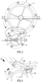
- Figs. 1 and 2 show a basic principle. Power is supplied 3 to motor 1, which drives member 2 rotationally 12. Mounted on driving member 2 are cylindrical bar magnets 5. Member 2 rotates 12 close to, but does not contact, driven member 7 (as shown) and a magnet 5 engages with a magnet 11 located at the circumferences of members 2 and 7 respectively.
- the driving member and driven member are broadly planar, more preferably circular, disk-like or annular bodies. All magnets 5 and 11 are mounted normally so that (for example) their N poles are close to members 2 and 7, i.e. at the upper ends of Fig. 2 , and thus their S poles are at their distal ends. As shown ( Fig.
- members 2 and 7 are coplanar and thus magnets 5 and 11 are parallel to each other and approach with the two N poles adjacent and the two S poles adjacent so that a maximum repulsive force 14 ( Fig. 4 ) is generated causing driven member 7 to rotate 13 away from each magnet 5.
- the repulsive force is represented by double headed arrow 14 ( Fig. 4 ).
- driving member 2 When motor 1 is energised, driving member 2 will rotate and bring a magnet 5 towards a magnet 11, which will cause driven member 7 to turn. As member 2 reaches operating speed, the repeated repulsive 'kicks' 14 from magnets 5 to magnets 11 will synchronise the rotations 12 and 13; as member 2 carries four magnets 5 and member 7 has eight magnets 11, member 7 will rotate at half the speed of member 2.
- Member 7 drives an item 8, e.g. a pump, or a generator - thereby generating power - via shaft 9.
- the gearing ratio between driving 2 and driven 7 members ( Fig. 1 ) will depend on the relative numbers of magnets 5 and 11 respectively; typical ratios may be 2:1, 1:1 or 1:2, etc. in the Fig. 1 embodiment. As shown, the diameter of member 7 is greater than that of member 2 so the torque transmitted to shaft 9 will be greater than that in shaft 4.
- Fig. 3 is a copy of Fig. 1 but with the area of the interaction of magnets 5 and 11 indicated by ellipse A.
- Fig. 4 is an enlargement of area of ellipse A.
- the separation distance 6A between magnets 5 and 11 in the forward direction of motion (12, 13) is much smaller than the separation distance 6B between magnet 5 and the following magnet 11 (i.e. in the reverse sense of rotation).
- the attractive or repulsive force between two magnets is essentially inversely proportion to the square of the separation distance.
- the forward force F A is essentially proportional to 1/6A 2
- the reverse force F B is proportional to 1/6B 2 .
- to indicate the difference between F A and F B one may scale off Fig.
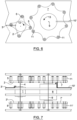
- FIG. 2 shows how the arrangement in Fig. 1 may be used to drive a further rotary output.
- driven magnets 11 become the driver, engaging with magnets 17 on member 19, causing rotation 21 about axis 18.
- the output 19 may be a rotary device (not shown), or a further power output 20.
- an axial input drive 4 ( Fig. 1 ) is taught, a circumferential input drive (not shown but similar to members 17-21) is equally possible.
- Figs. 6 and 7 show a second variation of the basic principle in which driving 2 and driven 7 members, with their magnets 5 and 11, are doubled up and shown as 2' and 7', and their magnets 5' and 11', respectively. This arrangement should increase the power transmitting capability of the gearing.
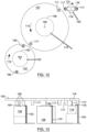
- Figs. 8 and 9 show the principle of the invention where the magnets 105 and 111 pass close to each other without touching, as opposed to inter-engaging ( Figs. 1-7 ).
- power is supplied 103 to motor 100, which drives member 102 rotationally 112.
- Member 102 rotates 112 close to, but clear of, driven member 107, as shown 106, and a magnet 105 engages with a magnet 111 located close to the circumference of member 107.
- all magnets 105 and 111 are mounted normally so that (for example) their N poles are close to members 102 and 107 and thus their S poles are at their distal ends.
- members 102 and 107 are coplanar and thus magnets 105 and 111 are parallel to each other and approach with the two N poles adjacent and the two S poles adjacent so that a maximum repulsive force 114 ( Fig. 9 ) is generated causing driven member 107 to rotate 113 away from each magnet 105.
- the repulsive force is represented by double headed arrow 114.
- Member 107 drives pump 108 via shaft 109 but may equally drive a generator to produce electrical power.
- An advantage of this ⁇ close passing' arrangement is that slippage can occur between driving 102 and driven 107 members, e.g. if the load on the driven member 107 becomes excessive. This will protect motor 100 from damage due to being stalled.
- both driving 102 and driven 107 members respectively carry only two magnets 105 and 111, each will rotate 112, 113 at the same speed though in opposite senses.
- the ratio of rotational speeds may be 2:1, 1:1 or 1:2, etc. in the Fig. 8 representation.
- the diameter of member 107 is greater than that of member 102 so the torque transmitted to shaft 109 will be greater than that in shaft 104.
- Figs. 10 and 11 show a variation of the arrangement of Figs. 8 and 9 in which driving member 102 is located parallel to, but below, the plane of the driven member 107.
- Spacers 115 maintain the close 106, but non-contact, abutting alignment of pluralities of magnets 105 and 111.
- magnets are mounted normally on members 102 and 107 respectively, again with the N and S poles directly abutting.
- This arrangement is more compact than that shown in Figs. 8 and 9 but the principle of operation is the same and the same reference numerals are used.
- Figs. 12 and 13 show a further variation of the principle of the invention, but with a second power take off via member 116, driven by the interaction of pluralities of magnets 111 and 117, to axle 118 and a robotic item 119 (alternatively a generator) and output 120.
- a single input 103 is used but provides two different outputs 109 and 119. All three members 102, 107 and 116 are coplanar.
- Embodiments of the invention may be adapted, as required, by changing the relative diameters of members 102, 107 and 116 and numbers of magnets in each plurality.
- a plurality of second takes off 116-120 may be provided, as required; in this way the apparatus of the invention could simultaneously drive a number of different robotic systems, e.g. on a space craft.
- Fig. 12 a two-stage power take off is taught and has been achieved in practice.
- motor 100 has to be powerful enough to provide the input force to drive the combination of the two magnetic repulsions 105-111 and 111-117 to produce useful outputs 109, 119.
- Figs. 8-13 the pluralities have shown only two driving 105 and two driven 111 magnets; this has been to teach the principle of the invention in a clear logical way.
- One method of increasing the transmitted power is shown in Figs. 14 and 15 , where the plurality of driving magnets 105A is used in pairs in a specially modified member 102A.
- the pairs of magnets 105A will give magnet 111A a 'double kick' as each passes i.e. increasing the torque transmission.
- each magnet 105A and 111A is doubled up.
- the repulsive force, as magnets 105A and 111A pass is potentially greater than that in the Figs. 8-13 representations.
- driven member 107 will not begin to rotate when driving member 102 is started. Under these circumstances, if driven member 107 is turning 113 before motor 101 is started, members 102 and 107 will automatically synchronise.
- a mass at a high point will have potential energy (mgh, where m is the mass, g is the acceleration due to gravity and h is the height) and, if it is allowed to roll down a hill, it will convert a part of this into kinetic energy (1 ⁇ 2mv 2 , where v is the velocity). During the conversion, part of the potential energy will be lost due to friction and air resistance.
- the input power source and the repulsive forces between permanent magnets in the pluralities of magnets combine to produce the power in the output member.
- commutators (not shown) would be provided coaxially with some/all of axles 4, 9, 18, 104, 109 & 118 and power to energise the electromagnets, i.e. the equivalents to 5, 11, 17, 105, 111 &117 would be supplied for only the appropriate proximity, solid, rotational angles of members 2, 7, 16, 102, 107 & 116.
- Electromagnets may have a marginal advantage over permanent magnets in that the magnetism may not be energised until the rotation 12, 13 ( Figs. 1-7 ) and 112, 113 ( Figs. 8-15 ) has reached the point of closest proximity of magnets 5 and 11, thus eliminating the small reverse 'kick' (FB, 6B ⁇ Fig. 4 ⁇ ) as magnets approach prior to the strong forward 'kick' (FA, 6A) at and after closest proximity as they move away from each other.
- Combinations of bar magnets and electromagnets are equally possible on the same, or different, driving and/or driven members.
Landscapes
- Engineering & Computer Science (AREA)
- Power Engineering (AREA)
- Dynamo-Electric Clutches, Dynamo-Electric Brakes (AREA)
Claims (11)
- Appareil d'accouplement magnétique, pour transmettre un entraînement depuis un élément d'entraînement (102) à un élément entraîné (107), dans lequel l'élément d'entraînement (102) a au moins un premier aimant (105) et l'élément entraîné (107) a un ou plusieurs seconds aimants (111), dans lequel l'au moins un premier aimant (105) est agencé sur l'élément d'entraînement (102) de sorte que son axe Nord-Sud soit sensiblement parallèle à un axe de rotation de l'élément d'entraînement, dans lequel l'un ou plusieurs seconds aimants (111) sont agencés sur l'élément entraîné (107) de sorte que leurs axes Nord-Sud soient sensiblement parallèles à un axe de rotation de l'élément entraîné (107), dans lequel l'au moins un premier aimant (105) et l'un ou plusieurs seconds aimants (111) sont agencés sensiblement dans le même sens et sensiblement parallèles les uns aux autres de sorte que lorsqu'un aimant de l'au moins un premier aimant (105) s'approche d'un aimant dans l'un ou plusieurs seconds aimants (111), les deux pôles pointant le Nord soient adjacents et les deux pôles pointant le Sud soient également adjacents, provoquant ainsi la génération d'une force doublement répulsive tandis l'élément d'entraînement (102) tourne (112), ce qui entraîne la rotation (112) de l'élément entraîné (107), dans lequel l'au moins un premier aimant (105) et l'un ou plusieurs seconds aimants (111) sont agencés pour rester dans des lieux circulaires espacés tandis l'élément d'entraînement (102) et l'élément entraîné (107) tournent (112, 113).
- Appareil selon l'une quelconque des revendications précédentes, dans lequel il y a une pluralité de premiers aimants (105) agencés sur l'élément d'entraînement.
- Appareil selon la revendication 2,
dans lequel les aimants sont agencés sur l'élément d'entraînement (102) et l'élément entraîné (107) de sorte que tandis que l'élément d'entraînement (102) tourne (112), une succession de premiers aimants (105) est amenée en apposition à une succession de seconds aimants (111). - Appareil selon l'une quelconque des revendications précédentes, dans lequel l'élément d'entraînement (102) est agencé en utilisation pour être entraîné par une source de puissance d'entrée (100), et dans lequel la source de puissance d'entrée comprend une puissance électrique ou une puissance mécanique.
- Appareil selon l'une quelconque des revendications précédentes, dans lequel l'élément entraîné (107) est connecté à un dispositif de sortie (108), et dans lequel le dispositif de sortie comprend l'un quelconque d'une pompe, d'un générateur ou d'un engrenage.
- Appareil selon l'une quelconque des revendications précédentes, dans lequel l'élément d'entraînement (102) comprend des premiers aimants (105) agencés autour d'une périphérie de l'élément d'entraînement (102) à des emplacements espacés, et dans lequel
l'élément entraîné (107) comprend des seconds aimants (111) agencés autour d'une périphérie de l'élément entraîné (107) à des emplacements espacés. - Appareil selon l'une quelconque des revendications précédentes, dans lequel l'élément d'entraînement (102) comprend un arbre (104) et un corps sensiblement plan sur lequel les aimants sont montés.
- Appareil selon l'une quelconque des revendications précédentes, dans lequel l'élément entraîné (107) comprend un arbre (109) et un corps sensiblement plan sur lequel les aimants sont montés.
- Appareil selon la revendication 7 ou 8,
dans lequel au moins l'un parmi l'élément d'entraînement (102) ou l'élément entraîné (107) comprend un arbre et un corps sensiblement plan sur lequel les aimants respectifs sont montés et dans lequel le corps plan comprend un corps en forme de disque ou annulaire. - Appareil selon la revendication 7 et 8,
dans lequel à la fois l'élément d'entraînement (102) et l'élément entraîné (107) comprennent un arbre et un corps sensiblement plan sur lequel les aimants respectifs sont montés et dans lequel le corps plan de l'élément d'entraînement (102) et le corps plan de l'élément entraîné (107) se trouvent dans un plan sensiblement commun. - Procédé de réalisation d'un accouplement magnétique entre un élément d'entraînement (102) et un élément entraîné (107), l'élément d'entraînement (102) ayant au moins un premier aimant (105) et l'élément entraîné (107) ayant un ou plusieurs seconds aimants (111), dans lequel l'au moins un premier aimant (105) est agencé sur l'élément d'entraînement (102) de sorte que son axe Nord-Sud soit sensiblement parallèle à un axe de rotation de l'élément d'entraînement, dans lequel l'un ou plusieurs seconds aimants (111) sont agencés sur l'élément entraîné (107) de sorte que leurs axes Nord-Sud soient sensiblement parallèles à un axe de rotation de l'élément entraîné (107), dans lequel l'au moins un premier aimant (105) et l'un ou plusieurs seconds aimants (111) sont agencés sensiblement dans le même sens et sensiblement parallèles les uns aux autres de sorte que lorsqu'un aimant de l'au moins un premier aimant (105) s'approche d'un aimant dans l'un ou plusieurs seconds aimants (111), les deux pôles pointant le Nord soient adjacents et les deux pôles pointant le sud soient également adjacents, provoquant ainsi la génération d'une force doublement répulsive tandis que l'élément d'entraînement (102) tourne (112) ce qui entraîne la rotation (112) de l'élément entraîné (107), dans lequel le procédé comprend l'agencement de l'au moins un premier aimant (105) et de l'un ou plusieurs seconds aimants (111) pour rester dans des lieux circulaires espacés tandis que l'élément d'entraînement (102) et l'élément entraîné (107) tournent (113).
Applications Claiming Priority (4)
| Application Number | Priority Date | Filing Date | Title |
|---|---|---|---|
| GB1703452.1A GB2560187A (en) | 2017-03-03 | 2017-03-03 | Magnetic power transmission |
| GBGB1721117.8A GB201721117D0 (en) | 2017-03-03 | 2017-12-18 | Magnetic energy conversion |
| GBGB1800156.0A GB201800156D0 (en) | 2017-03-03 | 2018-01-05 | Magnetic energy conversion |
| PCT/GB2018/050494 WO2018158562A1 (fr) | 2017-03-03 | 2018-02-27 | Couplage magnétique et procédé |
Publications (2)
| Publication Number | Publication Date |
|---|---|
| EP3590182A1 EP3590182A1 (fr) | 2020-01-08 |
| EP3590182B1 true EP3590182B1 (fr) | 2023-07-26 |
Family
ID=58543971
Family Applications (1)
| Application Number | Title | Priority Date | Filing Date |
|---|---|---|---|
| EP18715061.0A Active EP3590182B1 (fr) | 2017-03-03 | 2018-02-27 | Couplage magnétique et procédé |
Country Status (6)
| Country | Link |
|---|---|
| US (1) | US20200076289A1 (fr) |
| EP (1) | EP3590182B1 (fr) |
| JP (1) | JP2020510169A (fr) |
| CN (1) | CN110383653A (fr) |
| GB (4) | GB2560187A (fr) |
| WO (1) | WO2018158562A1 (fr) |
Families Citing this family (1)
| Publication number | Priority date | Publication date | Assignee | Title |
|---|---|---|---|---|
| EP4202563A1 (fr) * | 2021-12-23 | 2023-06-28 | The Swatch Group Research and Development Ltd | Mécanisme horloger muni d'un engrenage magnétique |
Family Cites Families (14)
| Publication number | Priority date | Publication date | Assignee | Title |
|---|---|---|---|---|
| GB549590A (en) * | 1940-08-21 | 1942-11-27 | British Thomson Houston Co Ltd | Improvements in and relating to magnetic gearing |
| US2243555A (en) * | 1940-08-21 | 1941-05-27 | Gen Electric | Magnet gearing |
| BE791979A (fr) * | 1971-12-02 | 1973-03-16 | Baermann Max | Engrenage a vis sans fin a aimantation permanente |
| FR2546253B1 (fr) * | 1983-05-20 | 1988-09-16 | Aaton Sa | Dispositif d'accouplement magnetique entre deux arbres rotatifs menant et mene |
| AU2001295273A1 (en) * | 2000-10-11 | 2002-04-22 | Andrew Boyd French | Drive apparatus |
| US6998723B2 (en) * | 2002-08-06 | 2006-02-14 | Carl Cheung Tung Kong | Electrical generating system having a magnetic coupling |
| JP2005253292A (ja) * | 2004-02-04 | 2005-09-15 | Techno Network Shikoku Co Ltd | 高トルク伝達非接触歯車 |
| EP1875108A1 (fr) * | 2005-04-08 | 2008-01-09 | Andrew Boyd French | Dispositif a entrainement magnetique |
| CN100535449C (zh) * | 2005-07-19 | 2009-09-02 | 磐石国际股份有限公司 | 磁动式多轴风扇及其动力传输系统 |
| WO2007055421A1 (fr) * | 2005-11-10 | 2007-05-18 | Crystalbay Co., Ltd. | Dispositif de transmission de rotation exempt de contact |
| CN101262165A (zh) * | 2007-03-06 | 2008-09-10 | 刘新广 | 磁传动器 |
| DE102009056227A1 (de) * | 2009-11-28 | 2011-06-09 | Christian Zschoch | Magnetisches Zahnrad |
| US9337712B2 (en) * | 2011-03-04 | 2016-05-10 | Allen G. Storaasli | Eccentric magnetic gear system based on repulsion |
| CN107534382A (zh) * | 2015-05-20 | 2018-01-02 | 费斯托股份有限两合公司 | 传动机构 |
-
2017
- 2017-03-03 GB GB1703452.1A patent/GB2560187A/en not_active Withdrawn
- 2017-12-18 GB GBGB1721117.8A patent/GB201721117D0/en not_active Ceased
-
2018
- 2018-01-05 GB GBGB1800156.0A patent/GB201800156D0/en not_active Ceased
- 2018-02-27 US US16/489,449 patent/US20200076289A1/en not_active Abandoned
- 2018-02-27 WO PCT/GB2018/050494 patent/WO2018158562A1/fr active Application Filing
- 2018-02-27 CN CN201880015445.3A patent/CN110383653A/zh active Pending
- 2018-02-27 GB GB1803141.9A patent/GB2560260A/en not_active Withdrawn
- 2018-02-27 EP EP18715061.0A patent/EP3590182B1/fr active Active
- 2018-02-27 JP JP2019547417A patent/JP2020510169A/ja active Pending
Also Published As
| Publication number | Publication date |
|---|---|
| WO2018158562A1 (fr) | 2018-09-07 |
| GB2560187A (en) | 2018-09-05 |
| GB201803141D0 (en) | 2018-04-11 |
| US20200076289A1 (en) | 2020-03-05 |
| GB201721117D0 (en) | 2018-01-31 |
| JP2020510169A (ja) | 2020-04-02 |
| GB201800156D0 (en) | 2018-02-21 |
| GB2560260A (en) | 2018-09-05 |
| EP3590182A1 (fr) | 2020-01-08 |
| GB201703452D0 (en) | 2017-04-19 |
| CN110383653A (zh) | 2019-10-25 |
Similar Documents
| Publication | Publication Date | Title |
|---|---|---|
| EP1332298B1 (fr) | Appareil d'entrainement | |
| US7233088B2 (en) | Torque converter and system using the same | |
| KR101894672B1 (ko) | 정, 역방향 상대속도를 이용한 발전시스템 | |
| WO2006133703A1 (fr) | Dispositif magnétique pour le transfert de forces | |
| EP3590182B1 (fr) | Couplage magnétique et procédé | |
| US6369477B1 (en) | Roller-type electric motor | |
| WO2010000302A1 (fr) | Transmission à friction harmonique | |
| EP3139040A1 (fr) | Dispositif d'entraînement en rotation | |
| EP1340309B1 (fr) | Procede et dispositif de transmission magnetique d'une force | |
| Muruganandam et al. | Design and implementation of a novel magnetic bevel gear | |
| JPH05231299A (ja) | 回転装置 | |
| KR102214726B1 (ko) | 자력을 이용한 동력보조장치 | |
| Sapsalev et al. | Structural model of a magnetic coupling | |
| US20210075308A1 (en) | Systems and methods for magnetic rotational coupling devices | |
| RU2210849C1 (ru) | Электромеханический рекуперативный преобразователь | |
| CN110943597B (zh) | 一种磁力驱动装置 | |
| JP4759489B2 (ja) | 非接触動力伝達装置 | |
| KR20220157614A (ko) | 영구자석의 자력을 이용한 자기자력 동력 보조 장치 | |
| JPH06280954A (ja) | 磁石式ボール遊星減速装置 | |
| WO2019102377A1 (fr) | Moteur et agencement de convertisseur de vitesse | |
| JPH02223375A (ja) | 磁気歯車装置 | |
| PL233000B1 (pl) | Przekładnia magnetyczna |
Legal Events
| Date | Code | Title | Description |
|---|---|---|---|
| STAA | Information on the status of an ep patent application or granted ep patent |
Free format text: STATUS: UNKNOWN |
|
| STAA | Information on the status of an ep patent application or granted ep patent |
Free format text: STATUS: THE INTERNATIONAL PUBLICATION HAS BEEN MADE |
|
| PUAI | Public reference made under article 153(3) epc to a published international application that has entered the european phase |
Free format text: ORIGINAL CODE: 0009012 |
|
| STAA | Information on the status of an ep patent application or granted ep patent |
Free format text: STATUS: REQUEST FOR EXAMINATION WAS MADE |
|
| 17P | Request for examination filed |
Effective date: 20190906 |
|
| AK | Designated contracting states |
Kind code of ref document: A1 Designated state(s): AL AT BE BG CH CY CZ DE DK EE ES FI FR GB GR HR HU IE IS IT LI LT LU LV MC MK MT NL NO PL PT RO RS SE SI SK SM TR |
|
| AX | Request for extension of the european patent |
Extension state: BA ME |
|
| DAV | Request for validation of the european patent (deleted) | ||
| DAX | Request for extension of the european patent (deleted) | ||
| STAA | Information on the status of an ep patent application or granted ep patent |
Free format text: STATUS: EXAMINATION IS IN PROGRESS |
|
| STAA | Information on the status of an ep patent application or granted ep patent |
Free format text: STATUS: EXAMINATION IS IN PROGRESS |
|
| 17Q | First examination report despatched |
Effective date: 20200922 |
|
| GRAP | Despatch of communication of intention to grant a patent |
Free format text: ORIGINAL CODE: EPIDOSNIGR1 |
|
| STAA | Information on the status of an ep patent application or granted ep patent |
Free format text: STATUS: GRANT OF PATENT IS INTENDED |
|
| INTG | Intention to grant announced |
Effective date: 20220830 |
|
| RAP3 | Party data changed (applicant data changed or rights of an application transferred) |
Owner name: CLEANER WORLD TECHNOLOGIES LTD |
|
| GRAS | Grant fee paid |
Free format text: ORIGINAL CODE: EPIDOSNIGR3 |
|
| GRAA | (expected) grant |
Free format text: ORIGINAL CODE: 0009210 |
|
| STAA | Information on the status of an ep patent application or granted ep patent |
Free format text: STATUS: THE PATENT HAS BEEN GRANTED |
|
| AK | Designated contracting states |
Kind code of ref document: B1 Designated state(s): AL AT BE BG CH CY CZ DE DK EE ES FI FR GB GR HR HU IE IS IT LI LT LU LV MC MK MT NL NO PL PT RO RS SE SI SK SM TR |
|
| REG | Reference to a national code |
Ref country code: CH Ref legal event code: EP |
|
| REG | Reference to a national code |
Ref country code: DE Ref legal event code: R096 Ref document number: 602018054011 Country of ref document: DE |
|
| REG | Reference to a national code |
Ref country code: IE Ref legal event code: FG4D |
|
| REG | Reference to a national code |
Ref country code: LT Ref legal event code: MG9D |
|
| REG | Reference to a national code |
Ref country code: NL Ref legal event code: MP Effective date: 20230726 |
|
| REG | Reference to a national code |
Ref country code: AT Ref legal event code: MK05 Ref document number: 1593102 Country of ref document: AT Kind code of ref document: T Effective date: 20230726 |
|
| PG25 | Lapsed in a contracting state [announced via postgrant information from national office to epo] |
Ref country code: NL Free format text: LAPSE BECAUSE OF FAILURE TO SUBMIT A TRANSLATION OF THE DESCRIPTION OR TO PAY THE FEE WITHIN THE PRESCRIBED TIME-LIMIT Effective date: 20230726 |
|
| PG25 | Lapsed in a contracting state [announced via postgrant information from national office to epo] |
Ref country code: GR Free format text: LAPSE BECAUSE OF FAILURE TO SUBMIT A TRANSLATION OF THE DESCRIPTION OR TO PAY THE FEE WITHIN THE PRESCRIBED TIME-LIMIT Effective date: 20231027 |
|
| PG25 | Lapsed in a contracting state [announced via postgrant information from national office to epo] |
Ref country code: IS Free format text: LAPSE BECAUSE OF FAILURE TO SUBMIT A TRANSLATION OF THE DESCRIPTION OR TO PAY THE FEE WITHIN THE PRESCRIBED TIME-LIMIT Effective date: 20231126 |
|
| PG25 | Lapsed in a contracting state [announced via postgrant information from national office to epo] |
Ref country code: SE Free format text: LAPSE BECAUSE OF FAILURE TO SUBMIT A TRANSLATION OF THE DESCRIPTION OR TO PAY THE FEE WITHIN THE PRESCRIBED TIME-LIMIT Effective date: 20230726 Ref country code: RS Free format text: LAPSE BECAUSE OF FAILURE TO SUBMIT A TRANSLATION OF THE DESCRIPTION OR TO PAY THE FEE WITHIN THE PRESCRIBED TIME-LIMIT Effective date: 20230726 Ref country code: PT Free format text: LAPSE BECAUSE OF FAILURE TO SUBMIT A TRANSLATION OF THE DESCRIPTION OR TO PAY THE FEE WITHIN THE PRESCRIBED TIME-LIMIT Effective date: 20231127 Ref country code: NO Free format text: LAPSE BECAUSE OF FAILURE TO SUBMIT A TRANSLATION OF THE DESCRIPTION OR TO PAY THE FEE WITHIN THE PRESCRIBED TIME-LIMIT Effective date: 20231026 Ref country code: LV Free format text: LAPSE BECAUSE OF FAILURE TO SUBMIT A TRANSLATION OF THE DESCRIPTION OR TO PAY THE FEE WITHIN THE PRESCRIBED TIME-LIMIT Effective date: 20230726 Ref country code: LT Free format text: LAPSE BECAUSE OF FAILURE TO SUBMIT A TRANSLATION OF THE DESCRIPTION OR TO PAY THE FEE WITHIN THE PRESCRIBED TIME-LIMIT Effective date: 20230726 Ref country code: IS Free format text: LAPSE BECAUSE OF FAILURE TO SUBMIT A TRANSLATION OF THE DESCRIPTION OR TO PAY THE FEE WITHIN THE PRESCRIBED TIME-LIMIT Effective date: 20231126 Ref country code: HR Free format text: LAPSE BECAUSE OF FAILURE TO SUBMIT A TRANSLATION OF THE DESCRIPTION OR TO PAY THE FEE WITHIN THE PRESCRIBED TIME-LIMIT Effective date: 20230726 Ref country code: GR Free format text: LAPSE BECAUSE OF FAILURE TO SUBMIT A TRANSLATION OF THE DESCRIPTION OR TO PAY THE FEE WITHIN THE PRESCRIBED TIME-LIMIT Effective date: 20231027 Ref country code: FI Free format text: LAPSE BECAUSE OF FAILURE TO SUBMIT A TRANSLATION OF THE DESCRIPTION OR TO PAY THE FEE WITHIN THE PRESCRIBED TIME-LIMIT Effective date: 20230726 Ref country code: AT Free format text: LAPSE BECAUSE OF FAILURE TO SUBMIT A TRANSLATION OF THE DESCRIPTION OR TO PAY THE FEE WITHIN THE PRESCRIBED TIME-LIMIT Effective date: 20230726 |
|
| PG25 | Lapsed in a contracting state [announced via postgrant information from national office to epo] |
Ref country code: PL Free format text: LAPSE BECAUSE OF FAILURE TO SUBMIT A TRANSLATION OF THE DESCRIPTION OR TO PAY THE FEE WITHIN THE PRESCRIBED TIME-LIMIT Effective date: 20230726 |
|
| PG25 | Lapsed in a contracting state [announced via postgrant information from national office to epo] |
Ref country code: ES Free format text: LAPSE BECAUSE OF FAILURE TO SUBMIT A TRANSLATION OF THE DESCRIPTION OR TO PAY THE FEE WITHIN THE PRESCRIBED TIME-LIMIT Effective date: 20230726 |
|
| PG25 | Lapsed in a contracting state [announced via postgrant information from national office to epo] |
Ref country code: SM Free format text: LAPSE BECAUSE OF FAILURE TO SUBMIT A TRANSLATION OF THE DESCRIPTION OR TO PAY THE FEE WITHIN THE PRESCRIBED TIME-LIMIT Effective date: 20230726 Ref country code: RO Free format text: LAPSE BECAUSE OF FAILURE TO SUBMIT A TRANSLATION OF THE DESCRIPTION OR TO PAY THE FEE WITHIN THE PRESCRIBED TIME-LIMIT Effective date: 20230726 Ref country code: ES Free format text: LAPSE BECAUSE OF FAILURE TO SUBMIT A TRANSLATION OF THE DESCRIPTION OR TO PAY THE FEE WITHIN THE PRESCRIBED TIME-LIMIT Effective date: 20230726 Ref country code: EE Free format text: LAPSE BECAUSE OF FAILURE TO SUBMIT A TRANSLATION OF THE DESCRIPTION OR TO PAY THE FEE WITHIN THE PRESCRIBED TIME-LIMIT Effective date: 20230726 Ref country code: DK Free format text: LAPSE BECAUSE OF FAILURE TO SUBMIT A TRANSLATION OF THE DESCRIPTION OR TO PAY THE FEE WITHIN THE PRESCRIBED TIME-LIMIT Effective date: 20230726 Ref country code: CZ Free format text: LAPSE BECAUSE OF FAILURE TO SUBMIT A TRANSLATION OF THE DESCRIPTION OR TO PAY THE FEE WITHIN THE PRESCRIBED TIME-LIMIT Effective date: 20230726 Ref country code: SK Free format text: LAPSE BECAUSE OF FAILURE TO SUBMIT A TRANSLATION OF THE DESCRIPTION OR TO PAY THE FEE WITHIN THE PRESCRIBED TIME-LIMIT Effective date: 20230726 |
|
| PGFP | Annual fee paid to national office [announced via postgrant information from national office to epo] |
Ref country code: DE Payment date: 20240219 Year of fee payment: 7 Ref country code: GB Payment date: 20240215 Year of fee payment: 7 |