EP3589970B1 - Method and system for obtaining an adaptive angle-doppler ambiguity function in mimo radars - Google Patents
Method and system for obtaining an adaptive angle-doppler ambiguity function in mimo radars Download PDFInfo
- Publication number
- EP3589970B1 EP3589970B1 EP18706764.0A EP18706764A EP3589970B1 EP 3589970 B1 EP3589970 B1 EP 3589970B1 EP 18706764 A EP18706764 A EP 18706764A EP 3589970 B1 EP3589970 B1 EP 3589970B1
- Authority
- EP
- European Patent Office
- Prior art keywords
- transmit
- denotes
- doppler
- pcm
- angle
- Prior art date
- Legal status (The legal status is an assumption and is not a legal conclusion. Google has not performed a legal analysis and makes no representation as to the accuracy of the status listed.)
- Active
Links
- 238000000034 method Methods 0.000 title claims description 54
- 230000003044 adaptive effect Effects 0.000 title claims description 7
- 238000012545 processing Methods 0.000 claims description 16
- 230000007704 transition Effects 0.000 claims description 16
- 230000002596 correlated effect Effects 0.000 claims description 14
- 230000000875 corresponding effect Effects 0.000 claims description 13
- 239000011159 matrix material Substances 0.000 claims description 8
- 238000005311 autocorrelation function Methods 0.000 claims description 6
- 238000005070 sampling Methods 0.000 claims description 6
- 230000005855 radiation Effects 0.000 claims description 5
- 238000012935 Averaging Methods 0.000 claims description 4
- 238000005314 correlation function Methods 0.000 claims description 4
- 230000000694 effects Effects 0.000 claims description 4
- 230000005540 biological transmission Effects 0.000 claims description 3
- 238000002156 mixing Methods 0.000 claims description 3
- 230000008878 coupling Effects 0.000 description 20
- 238000010168 coupling process Methods 0.000 description 20
- 238000005859 coupling reaction Methods 0.000 description 20
- 238000013461 design Methods 0.000 description 18
- 238000004088 simulation Methods 0.000 description 14
- 230000008569 process Effects 0.000 description 11
- 238000013459 approach Methods 0.000 description 9
- 238000001514 detection method Methods 0.000 description 9
- 238000003491 array Methods 0.000 description 6
- 238000007493 shaping process Methods 0.000 description 6
- 230000008901 benefit Effects 0.000 description 5
- 230000004044 response Effects 0.000 description 5
- 230000001629 suppression Effects 0.000 description 5
- 230000006978 adaptation Effects 0.000 description 3
- 238000012512 characterization method Methods 0.000 description 3
- 230000001427 coherent effect Effects 0.000 description 3
- 230000001419 dependent effect Effects 0.000 description 3
- 230000002708 enhancing effect Effects 0.000 description 3
- 230000015572 biosynthetic process Effects 0.000 description 2
- 230000001276 controlling effect Effects 0.000 description 2
- 230000007423 decrease Effects 0.000 description 2
- 238000005286 illumination Methods 0.000 description 2
- 238000011835 investigation Methods 0.000 description 2
- 230000005012 migration Effects 0.000 description 2
- 238000013508 migration Methods 0.000 description 2
- 230000000116 mitigating effect Effects 0.000 description 2
- 230000002123 temporal effect Effects 0.000 description 2
- 241001188564 Gymnosoma par Species 0.000 description 1
- 238000007476 Maximum Likelihood Methods 0.000 description 1
- 238000004458 analytical method Methods 0.000 description 1
- 230000035559 beat frequency Effects 0.000 description 1
- 230000002457 bidirectional effect Effects 0.000 description 1
- 230000021615 conjugation Effects 0.000 description 1
- 238000009795 derivation Methods 0.000 description 1
- 238000011161 development Methods 0.000 description 1
- 230000005284 excitation Effects 0.000 description 1
- 238000000605 extraction Methods 0.000 description 1
- 238000001914 filtration Methods 0.000 description 1
- 230000006872 improvement Effects 0.000 description 1
- 230000004807 localization Effects 0.000 description 1
- 230000000873 masking effect Effects 0.000 description 1
- 230000007246 mechanism Effects 0.000 description 1
- 230000003071 parasitic effect Effects 0.000 description 1
- 230000001902 propagating effect Effects 0.000 description 1
- 230000008054 signal transmission Effects 0.000 description 1
- 230000003595 spectral effect Effects 0.000 description 1
- 238000001228 spectrum Methods 0.000 description 1
- 230000001360 synchronised effect Effects 0.000 description 1
- 238000003786 synthesis reaction Methods 0.000 description 1
- 230000017105 transposition Effects 0.000 description 1
Images


Classifications
-
- G—PHYSICS
- G01—MEASURING; TESTING
- G01S—RADIO DIRECTION-FINDING; RADIO NAVIGATION; DETERMINING DISTANCE OR VELOCITY BY USE OF RADIO WAVES; LOCATING OR PRESENCE-DETECTING BY USE OF THE REFLECTION OR RERADIATION OF RADIO WAVES; ANALOGOUS ARRANGEMENTS USING OTHER WAVES
- G01S13/00—Systems using the reflection or reradiation of radio waves, e.g. radar systems; Analogous systems using reflection or reradiation of waves whose nature or wavelength is irrelevant or unspecified
- G01S13/02—Systems using reflection of radio waves, e.g. primary radar systems; Analogous systems
- G01S13/06—Systems determining position data of a target
- G01S13/42—Simultaneous measurement of distance and other co-ordinates
-
- G—PHYSICS
- G01—MEASURING; TESTING
- G01S—RADIO DIRECTION-FINDING; RADIO NAVIGATION; DETERMINING DISTANCE OR VELOCITY BY USE OF RADIO WAVES; LOCATING OR PRESENCE-DETECTING BY USE OF THE REFLECTION OR RERADIATION OF RADIO WAVES; ANALOGOUS ARRANGEMENTS USING OTHER WAVES
- G01S13/00—Systems using the reflection or reradiation of radio waves, e.g. radar systems; Analogous systems using reflection or reradiation of waves whose nature or wavelength is irrelevant or unspecified
- G01S13/003—Bistatic radar systems; Multistatic radar systems
-
- G—PHYSICS
- G01—MEASURING; TESTING
- G01S—RADIO DIRECTION-FINDING; RADIO NAVIGATION; DETERMINING DISTANCE OR VELOCITY BY USE OF RADIO WAVES; LOCATING OR PRESENCE-DETECTING BY USE OF THE REFLECTION OR RERADIATION OF RADIO WAVES; ANALOGOUS ARRANGEMENTS USING OTHER WAVES
- G01S13/00—Systems using the reflection or reradiation of radio waves, e.g. radar systems; Analogous systems using reflection or reradiation of waves whose nature or wavelength is irrelevant or unspecified
- G01S13/02—Systems using reflection of radio waves, e.g. primary radar systems; Analogous systems
- G01S13/50—Systems of measurement based on relative movement of target
- G01S13/52—Discriminating between fixed and moving objects or between objects moving at different speeds
- G01S13/536—Discriminating between fixed and moving objects or between objects moving at different speeds using transmission of continuous unmodulated waves, amplitude-, frequency-, or phase-modulated waves
-
- G—PHYSICS
- G01—MEASURING; TESTING
- G01S—RADIO DIRECTION-FINDING; RADIO NAVIGATION; DETERMINING DISTANCE OR VELOCITY BY USE OF RADIO WAVES; LOCATING OR PRESENCE-DETECTING BY USE OF THE REFLECTION OR RERADIATION OF RADIO WAVES; ANALOGOUS ARRANGEMENTS USING OTHER WAVES
- G01S13/00—Systems using the reflection or reradiation of radio waves, e.g. radar systems; Analogous systems using reflection or reradiation of waves whose nature or wavelength is irrelevant or unspecified
- G01S13/88—Radar or analogous systems specially adapted for specific applications
- G01S13/93—Radar or analogous systems specially adapted for specific applications for anti-collision purposes
- G01S13/931—Radar or analogous systems specially adapted for specific applications for anti-collision purposes of land vehicles
-
- G—PHYSICS
- G01—MEASURING; TESTING
- G01S—RADIO DIRECTION-FINDING; RADIO NAVIGATION; DETERMINING DISTANCE OR VELOCITY BY USE OF RADIO WAVES; LOCATING OR PRESENCE-DETECTING BY USE OF THE REFLECTION OR RERADIATION OF RADIO WAVES; ANALOGOUS ARRANGEMENTS USING OTHER WAVES
- G01S7/00—Details of systems according to groups G01S13/00, G01S15/00, G01S17/00
- G01S7/02—Details of systems according to groups G01S13/00, G01S15/00, G01S17/00 of systems according to group G01S13/00
- G01S7/35—Details of non-pulse systems
- G01S7/352—Receivers
- G01S7/354—Extracting wanted echo-signals
-
- H—ELECTRICITY
- H01—ELECTRIC ELEMENTS
- H01Q—ANTENNAS, i.e. RADIO AERIALS
- H01Q21/00—Antenna arrays or systems
- H01Q21/29—Combinations of different interacting antenna units for giving a desired directional characteristic
- H01Q21/293—Combinations of different interacting antenna units for giving a desired directional characteristic one unit or more being an array of identical aerial elements
Definitions
- ⁇ ( i c ) denotes the phase center position at the transmit array and the switching across chirps is denoted by the chirp index i c
- j is the complex number.
- the expression for ⁇ k ⁇ ⁇ ′ denotes the Fourier transform of the PDF and can be seen as the spatial spectrum.
- a further advantage of the invention is to provide for a waveform adaptation mechanism where the correlated PCM is adapted to enhance the AF in certain regions towards obtaining better detection of weak targets masked by strong targets.
- the PDF ( ⁇ ⁇ ( i c 1 ) ) and joint PDF ( ⁇ ⁇ ( i c 1 ), ⁇ ( i c 2 ) ) of the PCM are used for this exercise.
- Fig.1 shows schematically a System Model for a FMCW PCM system according to an embodiment.
- the local oscillator output is a consecutive set of FMCW chirps, where each chirp is radiated in a random alternating fashion with just one transmit antenna element being active at a time.
- the collocated transmit antenna elements are mounted along the x -axis with an inter-element spacing of d T and a total number of N antenna elements. From the sparse transmit array structure the chirp sequence is propagating towards K multiple, in general moving, point scatters.
- the transmitted signal u ⁇ C I c ⁇ 1 consists of I c FMCW chirps, while each chirp contains a different phase center position ⁇ ( i c ) at the transmit array.
- Figure 2 illustrates the relationship of random process and PCM.
- the phase center can assume any real position within the virtual array by appropriate modulation scheme.
- the PDF ⁇ ⁇ ( i c ) is continuous; however, the PDF is discrete for scenarios involving antenna switching.
- the coupling term is dependent on the rectangular window function, W ( ⁇ D ⁇ ′ p , and the Fourier transform of the correlation function of PCM.
- This estimate can be used for signal design and the filter coefficients h ( ⁇ ) can be adjusted to optimize the SINR in regions where it is poor.
- s d a T,K ⁇ a R,K , where a T , K is a I c ⁇ 1 column vector with the ith element being e j ⁇ D ⁇ i c T c + k ⁇ ⁇ i c and a R , K is a M ⁇ 1 vector with the m th element being e jk ⁇ d R m
- Figure 3 illustrates the sinus cardinal like characteristic of the main lobe and its sidelobes.
- This sinus cardinal characteristic arises from the uniform PDF, therefore the resolution is maximal, while the sidelobes are high.
- the PDF is replaced by a Gaussian distribution, the resolution decreases and the sidelobes are suppressed, as it is illustrated in Figure 4 .
- the uniform and Gaussian PDF are depicted in Figure 8 and Figure 9 , respectively. Both PDF's are discrete, which illustrates the switching of the transmit array.
- the total number of CW pulses, in a coherent processing interval, is set to 512.
- FMCW Frequency Modulated Continuous Wave
- h ( ⁇ ) cos( ⁇ 0 ⁇ ) and the frequency ⁇ 0 is used as a design parameter. It should be noted that the choice of h ( ⁇ ) is one of the several possibilities.
- Figure 11 shows Doppler plane projection of the angle-Doppler ambiguity function for a colored random PCM.
- the two targets can be clearly resolved while the six grating lobes a ⁇ appear in between the two targets.
- Figure 12 shows Doppler plane projection of the angle-Doppler ambiguity function for a colored random PCM.
- the two targets can be clearly resolved while the six grading lobes a ⁇ appear in between the two targets.
- the colored random PCM is able to adaptively enhance certain regions of the sidelobe floor, such that the performance in terms of sidelobe floor increases and becomes similar to the side lobe floor of FDM for the optimized region but maintaining all properties of enhanced resolution and unambiguous Doppler range.
- This present invention provides a novel technique for enhanced low cost target detection of weak targets masked by strong reflections with the objective of suppressing the angle-Doppler coupling. It considers PCM based on random spatio-temporal modulations of the transmit array followed by a matched filter processing at receiver.
- PCM based on random spatio-temporal modulations of the transmit array followed by a matched filter processing at receiver.
- the method offers degrees of freedom, which act as design parameters to serve the objective. These include the PDF of the PCM which determines how often the transmission takes place from a given antenna as well as the nature of transitions from one antenna to the other (being correlated or otherwise). Simulation results have proven the capability of the proposed method by illustrating the desired shaping of the AF based on the choice of the PDF of PCM. This provides for an additional degree of freedom in designing radar systems for target discrimination.
Description
- The present invention generally relates to a wireless detection of objects using MIMO radar, e.g. for use in an automotive vehicle, and more particularly to a method and system for obtaining an angle-Doppler ambiguity function (AF) using random phase center motion (PCM); the invention also provides for a AF that can be made adaptive.
- In modern vehicles, radar systems are increasingly used, i.e. for sensing neighboring objects/targets (including other vehicles), for lane changing, collision avoidance and other driver assist functions.
- Unambiguous discrimination in radar systems with respect to angle, Doppler and range remains an area of investigation. Angular resolution is physically limited by the total antenna array size.
- Known techniques can be divided into three different topics which are all involving a kind of phase center motion but with different terminology.
- Synthetic aperture radar (SAR) utilize Displaced Phase Center Antenna (DPCA) technique, in order to improve the performance of Moving-Target-Indicator (MTI) radars mounted on moving platforms. By shifting the phase center of the antenna backward, the DPCA technique compensates for the forward motion of the moving platform so that, over a few pulse repetition intervals, the antenna is effectively stationary in space.
- Literature relating to antennas and propagation are mainly dealing with antenna beam pattern shaping and side lobe suppression. The background of those is lying more on antennas and their radiation characteristic and less in designing signal for coding. Nevertheless, the keywords phase center motion and 4 dimensional array (3 space dimension plus time) are introduced.
- Time Division Multiplexed (TDM) MIMO was introduced, where only one transmitter is active at a time in order to achieve orthogonal signals with respect to the angle of arrival. The TDM switching scheme itself can be interpreted as a kind of phase center motion for a single trajectory. Therefore, the relevant literature discloses the use of just a single trajectory and the presented trajectories are all suffering from target Doppler shifts and therefore not orthogonal in angle and Doppler simultaneously.
- More particularly, the known virtual Multiple-Input-Multiple-Output (MIMO) concept provides better angular resolution with the same number of antenna elements with respect to their phased array counterpart. The utilization of sparse arrays and orthogonal signals leads to a virtually filled array in the processing unit. Achieving orthogonality with respect to the transmit signals has been extensively discussed in the prior art.
- B. T. Perry, T. Levy, P. Bell, S. Davis, K. Kolodziej, N. O'Donoughue, J. S. Herd, "Low Cost Phased Array Radar for Applications in Engineering Education," in IEEE International Symposium on Phased Array Systems and Technology, 2013, discloses low cost Frequency Modulated Continuous Wave (FMCW) radar by switching the transmitters and receivers across FMCW chirps in a linear fashion. The consecutive switching scheme of transmit-receive-pairs yields a simple Discrete Fourier Transform (DFT) based received processing for resolving different angle of arrivals. The side-lobe suppression of the backscatter is addressed by virtual antenna overlapping; this decreases the virtual array aperture and therefore the angular resolution. However, linear switching of antenna elements across pulses results in angle-Doppler coupling.
- K. Rambach and B. Yang "Colocated MIMO Radar: Cramer-Rao Bound and Optimal Time Division Multiplexing for DOA Estimation of Moving Targets," in IEEE International Conference on Acoustics, Speech and Signal Processing (ICASSP), 2013, have investigated a time division multiplex (TDM) MIMO radar and analyzed the Direction of Arrival (DoA) estimation of a moving target. Using this Cramer-Rao bound (CRB), they deduced optimal TDM schemes such that the CRB is as small as for a stationary target. Simulations confirmed the theoretical results and showed that the Root mean square error (RMSE) of the maximum likelihood estimator is indeed as small as for a stationary target, if an optimal TDM scheme is used.
- C. Hammes, Y. Nijsure, B. Shankar, U. Schroeder, B. Ottersten, "Discrimination of Angle-Doppler Signatures using Arbitrary Phase Center Motion for MIMO Radars," in IEEE Radar Conference, 2017. (available online: http://wwwen.uni.lu/snt/people/christian_hammes), discloses techniques addressing the aforementioned coupling problem, in which a nonlinear approach is used. That is, a TDM technique is utilized as a virtual motion of the transmit phase center, called Phase Center Motion (PCM). The PCM technique has been introduced as a joint transmit-receive-time modulated array approach, where the PCM is independent of the target motion and, therefore, enables unambiguous multiple target discrimination by using inter-chirp modulation. While time modulated or four dimensional arrays are exploiting apparent antenna motion in an attempt to optimize the radiation pattern sidelobes, the PCM approach in Hammes et al (2017) exploits the time modulation such that a sparse array structure provides thumbtack response within the angle-Doppler domain, called angle-Doppler Ambiguity Function (AF).
- A problem addressed by the present invention is that known techniques do not exploit the space time coding of phase centre motion in every sense. In MIMO signal design they do not use phase centre motion as a design parameter at all. Therefore, all the signal design algorithms do not consider a complete new degree of freedom. In state of the art MIMO transmit signal design, they are considering time and space separately and not as a joint design parameter, which opens new avenues to signal design.
- In TDM MIMO the space time coding is used, but still only on trajectory on a one-dimensional array. The orthogonality in trajectory is not considered and investigated. Furthermore, strong angle Doppler coupling is a big drawback of this approach.
- In addition, techniques known from antenna and propagation literature neglect the capability of space time coding with regard to achieving orthogonality at all. To the contrary, they consider it as undesired because the splitting into orthogonal sequences yields a certain energy distribution.
- An object of the present invention is to provide waveforms that can be used to enhance resolution of targets in the angular domain (azimuth and elevation) and Doppler domain as well as interference mitigation in co-existence scenarios.
- In order to overcome the abovementioned problems, the present invention as defined in
claim 1 provides a method for obtaining an angle-Doppler ambiguity function (AF) for a target using multiple-input-multiple-output (MIMO) radar, the MIMO radar including a transmit antenna array, the transmit antenna array being at least one-dimensional and having a plurality of antenna elements, the method comprising: generating transmit signals for transmission by the transmit antenna array, the transmit signals defining at least a first transmit trajectory of a phase center within the transmit antenna array; transmitting the transmit signals using the transmit antenna array; receiving receive signals from the target, the receive signals resulting from the incidence of the transmit signals upon the target; and obtaining at least an angle-Doppler ambiguity function (AF) from the receive signals; wherein the first transmit trajectory corresponds to an amplitude modulation (AM) of the transmit signals so as to define a virtual array such that, in operation, the phase center undergoes random phase center motion (PCM) such that a phase center position within the transmit antenna array varies randomly with time. - The phase center position can be varied at any rate. In one embodiment, it is varied on a chirp-by-chirp basis (inter-chip PCM) and denoted by χ(ic ). The PCM χ(ic ) represents the position of the phase center in the transmit antenna array at the ic's chirp. In other embodiment, the phase center can be changed within a chirp (intra-chirp PCM) at a
pre-determined rate 1/Ts where Ts is the sampling rate; in such cases, the PCM χ(is ) represents the position of the phase center in the transmit antenna array at the is'th sample. - Preferably, the PCM χ(ic ) includes both correlated and uncorrelated transitions between positions within the transmit antenna array.
- Preferably, the phase center can assume any real position within the virtual array. The circumstance that one antenna element is active at the time enables orthogonality in time and therefore the virtual array can be constructed. This orthogonality is achieved both for correlated and uncorrelated transitions of the PCM. The problem which is addressed is of angle-Doppler coupling and the masking of weak reflections from the certain targets, e.g., children by strong reflections from other target e.g, truck.
- Preferably, the PCM χ(ic ) is described by a corresponding probability density function PDF ρ χ(ic ) and its temporal characteristic determining the nature of PCM transitions with regards to time - correlated or uncorrelated - this is referred to as the spectral property. Preferably, the transmit signals are such that a radiation characteristic


- Further, the correlation function for PCM induced phase vector


- When the PCM transitions are correlated, rχ (τ) is determined by ρ χ(i
c1 ),χ(ic1 -τ) the joint PDF of χ(i c1) and χ(i c2) and takes the form
- Preferably, the MIMO radar includes a receive antenna array, the receive antenna array being at least one-dimensional and having a plurality of antenna elements, wherein:
- receiving the receive signals from the object comprises receiving the receive signals using the receive antenna array; and
- the receive signals define at least a first receive trajectory of a phase center within the receive antenna array. Preferably, the first transmit trajectory and the first receive trajectory correspond or are identical.
- Preferably, obtaining at least an angle-Doppler ambiguity function (AF) from the receive signals comprises down-converting and digitizing the receive signals to obtain digitized receive signals written in matrix notation


- Particularly, the received samples, [ Y ] ic ,m (is ), at instance is for the ic chirp at the antenna m, containing a superposition of signals reflected from different targets and includes the angle (kφ ), Doppler (ωD
κ ) and range (ωBκ ) information are ordered in a three dimensional datacube. Using suitable designs of PCM helps mitigating the coupling of the angle and Doppler (kφ , ωDκ ). The traditional linear PCM strategies obtained from TDM MIMO cannot mitigate this coupling; in fact, they suffer due to the same. The random PCM provides a means to exploit virtual arrays without the coupling problem. - Preferably, obtaining at least an angle-Doppler ambiguity function (AF) from the receive signals further comprises rearranging the digitized receive signals in a data-cube, where a first dimension contains the intra-chirp samples, a second dimension denotes the inter-chirp samples and a third dimension refers to the data from each receive antenna element.
- Preferably, obtaining at least an angle-Doppler ambiguity function (AF) from the receive signals further comprises using a trajectory matched filter bank to extract Doppler and angular information from the receive signals. Preferably, a matched filter is applied to each dimension in order to compress the continuous wave such that the range, angle and Doppler information can be extracted.
- Preferably, obtaining at least an angle-Doppler ambiguity function (AF) from the receive signals further comprises squaring the output [ Y ] ic ,m (is ) of the matched filter(s) to obtained a squared filter output [ Ỹ ] p,q (l) for the p-th Doppler bin, q-th angular bin and l-th range bin, given by

- In an alternate embodiment [ Ỹ ] p,q (l) is computed using a three dimensional Fourier transform of new datacube where the raw signals are reordered according to

- In the sparse datacube

c ,is ):
- Preferably, according to one aspect of the invention wherein uncorrelated PCM transitions are considered, obtaining at least an angle-Doppler ambiguity function (AF) from the receive signals further comprises obtaining at least an angle-Doppler ambiguity function (AF) from the receive signals further comprises averaging [ Ỹ ] p,q (l) to obtain


κ (l)), the angle function (fφκ (q)), and fχ (q,p) denotes the coupling between the angle and Doppler. The function frκ (l), will have peaks corresponding to the target k for all angle and Doppler entries (q,p). Similarly, fφκ (q) will have a peak corresponding to the angle of arrival of the target k for all (l,p). However, the term fχ (q,p) couples angle and Doppler, thereby preventing resolvable peaks on the AF plot for Doppler. This leads to erroneous estimates of the target parameters or inability to resolve multiple targets. It should be noted, however, that fχ (q,p) involves the PCM and not the other terms. This provides us with a degree of freedom to choose the PCM towards decoupling angle and Doppler. - Preferably, according to another aspect of the invention wherein correlated PCM transitions are considered, obtaining at least an angle-Doppler ambiguity function (AF) from the receive signals further comprise obtaining at least an angle-Doppler ambiguity function (AF) from the receive signals further comprises averaging [ Ỹ ] p,q(l) to obtain


- According to an aspect of the invention, the E [[ Ỹ ] p,q (l)] can be controlled through the PDF (ρ χ(i
c1 )) and joint PDF (ρ χ(ic1 ),χ(ic2 )) of the PCM. - According to the invention defined in claim 13, there is provided a system for obtaining an angle-Doppler ambiguity function (AF) for a target using multiple-input-multiple-output (MIMO) radar, the system comprising a transmit antenna array, the transmit antenna array being at least one-dimensional and having a plurality of antenna elements; and processing circuitry, coupled to the transmit antenna array, the processing circuitry being configured to carry out the method of any of
claims 1 to 12. - The system preferably further comprises a receive antenna array coupled to the processing circuitry, the receive antenna array being at least one-dimensional and having a plurality of antenna elements.
- According to the invention defined in
claim 15, there is provided a non-transitory computer readable medium storing instructions which, when executed by processing circuitry of the system according to any one of claims 13 or 14, perform the method of any ofclaims 1 to 12. - An advantage of the invention, at least in embodiments, is to provide enhanced low cost target detection with the objective of suppressing the angle-Doppler coupling. It considers PCM based on random spatio-temporal modulations of the transmit array followed by a matched filter processing at receiver.
- A further advantage of the invention is to provide a framework for adapting these waveforms to enhance the AF at certain regions to mitigate the impact of strong targets and enhance the detection of weaker ones. Use of such waveforms leads to adaptive AF.
- A further advantage of the invention is to provide for a waveform adaptation mechanism where the correlated PCM is adapted to enhance the AF in certain regions towards obtaining better detection of weak targets masked by strong targets. As mentioned above (see e.g. par. [0028]), the PDF (ρ χ(i
c1 )) and joint PDF (ρ χ(ic1 ),χ(ic2 )) of the PCM are used for this exercise. - A further advantage is the ease of implementation - by just using a switched transmit array and a conventional beamforming technique at the receiver.
- Simulation results have proven the capability of the invention by illustrating the desired shaping of the AF based on the choice of the PDF.
- In another interesting aspect of the invention, the phase center motion (PCM) is designed based on the design of the autocorrelation function to impose nulls at specific Doppler locations, indexed by

- Another interesting aspect of the invention is the use of the method adaptively. One application of this is to detect a weak target in the vicinity of a strong target. Once a strong target had been detected, the PCM can be adapted to suppress it by minimizing the corresponding fχ (q,p) in equation (10) to suppres detected target. The process can be continued by suppressing detected targets in the scene and enhancing the illumination of the weaker targets.
- One embodiment of obtaining a auto-correlation function is to consider uncorrelated PCM with Gaussian PDF and filter it using a linear filter h(). This leads to,

- In one embodiment, the choice of the filter h(n) = cos(ω 0 n) for some frequency ω 0.
- In one embodiment, the system adaptation can take the following steps
- If there is no knowledge about the target scenario, it has to be assumed a worst case with no prior knowledge, where targets could be located anywhere and have the same RCS. It can be shown that for such a scenario, the white PCM provides the best SINR. Thus, h(τ)is chosen as an impulse.
- When knowledge about the scene is gathered by applying a matched filter threshold, an estimate of some target positions and their reflected power typically corresponding to strong targets, are determined. The responses corresponding to ones with weak backscatter may be missed by the threshold algorithm.
- This estimate can be used for signal design and the filter coefficients h(τ) can be adjusted to optimize the SINR in regions where it is poor.
- Further details and advantages of the present invention will be apparent from the following detailed description of not limiting embodiments with reference to the attached drawing, wherein:
-
Fig.1 shows schematically a System Model for a FMCW PCM system according to an embodiment; -
Fig. 2 shows random PCM properties with the PCM PDF (left side) and the uncorrelated phase center positions (right side) used in an embodiment; -
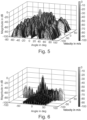
Fig.3 shows results in the form of an Angle-Doppler AF for single target with SNR = 10 dB, Ic = 512 and uniform PDF, obtained using an embodiment; -
Fig. 4 shows results in the form of an Angle-Doppler AF for single target with SNR = 10 dB, Ic = 512 and Gaussian PDF, obtained using an embodiment; -
Fig. 5 shows results in the form of an Angle-Doppler AF for single target with SNR = 10 dB, Ic = 128 and rectangular PDF, obtained using an embodiment; -
Fig. 6 shows results in the form of an Angle-Doppler AF for single target with SNR = 10 dB and Ic = 512 using one transmitter and 16 receivers by applying conventional beamforming; -
Fig. 7 shows results in the form of an Angle-Doppler AF for two target with SNR = .20 dB, Ic = 512 and uniform PDF, obtained using an embodiment; -
Fig. 8 shows a uniform discrete PDF for Ic = 512 chirps, in an embodiment; -
Fig. 9 illustrates a Gaussian discrete PDF for Ic = 512 chirps, in an embodiment; -
Fig. 10 illustrates the Doppler plane projection of the AF for a PCM with uncorrelated transitions; -
Fig. 11 shows Doppler plane projection of the AF for PCM with correlated transitions; and -
Fig. 12 shows Doppler plane projection of the AF for PCM with correlated transitions with a different window function thanFigure 11 . - In the following, like numerals will be used to indicate like elements.
- Embodiments of the present invention involve one or more of the following considerations. It should be noted that the presented FMCW implementation serves only for illustration purposes and the PCM principle is compatible with other radar waveforms such as OFDM or PMCW.
- A phase center motion is nothing other than a space time code of a certain signal. Therefore, one signal can have different space time codes. It can be shown that these space time codes can be orthogonal even though the excitation signal of the antenna elements is the same. The space time code can be expressed by trajectories within the antenna array, therefore, orthogonality in trajectory is introduced as a new degree of freedom.
- A random Phase Center Motion (PCM) technique is presented herein, based on Frequency Modulated Continuous Wave (FMCW) radar, in order to suppress the angle-Doppler coupling in Time Division Multiplex (TDM) Multiple-Input-Multiple-Output (MIMO) radar when employing sparse array structures. Embodiments exploit an apparently moving transmit platform or PCM due to spatio-temporal transmit array modulation. In particular, the techniques involve a framework utilizing a random PCM trajectory. The statistical characterization of the random PCM trajectory is devised, such that the PCM and the target motion coupling is minimal, while the angular resolution is increased by enabling the virtual MIMO concept. In more detail, embodiments of the present invention involve sidelobe suppression approaches within the angle-Doppler Ambiguity Function (AF) by introducing a phase center probability density function within the array. This allows for enhanced discrimination of multiple targets. Simulation results demonstrate the suppression angle-Doppler coupling by more than 30 dB, even though spatiotemporal transmit array modulation is done across chirps which leads usually to strong angle-Doppler coupling. Further, the temporal characteristics of the PCM, governed by the filtering operation, provide additional degrees of freedom for the adaptive design of AF. In particular, the correlation of PCM can be used to obtain desired AF in regions of interest towards enhancing the detection of weak targets in addition to the improvement in the angle-Doppler coupling.
- In contrast to the deterministic PCM in the above-references Hammes et al. paper, the present invention develops a framework for PCM trajectories where the phase center position varies randomly in time. Embodiments of the present invention utilize random PCM trajectories whose statistical characterization is based on uncorrelated transitions. Such a PCM implies high trajectory fluctuations, which are different from smooth target trajectories, due to the inertia of real targets. Therefore, PCM and the target trajectory can be decoupled due to their independent trajectories. In addition to the uncorrelated transitions, the PCM is described by the Probability Density Function (PDF). An interesting aspect is that the PDF impacts the angle-Doppler determination. Embodiments of the present invention involve the exploitation of the PDF to enhance target discrimination. Since the PCM trajectory parameters are known, a trajectory matched filter bank can be employed in order to extract Doppler and angular information. Embodiments of the present invention involve the development of a matched filter operating on the FMCW samples, chirps and the number of antennas to provide multiple target information. Throughout, the operator ∥·∥ is used for the l 2-norm. [·] η,γ defines a matrix entry with row index η and column index γ. The notation [·] η indicates a column vector element with the index η. The E {·} is the expectation operator. The symbol cC defines the set of complex numbers.
-
Fig.1 shows schematically a System Model for a FMCW PCM system according to an embodiment. The local oscillator output is a consecutive set of FMCW chirps, where each chirp is radiated in a random alternating fashion with just one transmit antenna element being active at a time. The collocated transmit antenna elements are mounted along the x-axis with an inter-element spacing of dT and a total number of N antenna elements. From the sparse transmit array structure the chirp sequence is propagating towards K multiple, in general moving, point scatters. - The back-scattered signal, which is a superposition of single target back-scatters, is captured by the dense receive array. The receive array contains M collocated antenna elements with an inter-element spacing of dR . Due to the FMCW scheme, the captured signal at each receiver is down-mixed by an instantaneous local oscillator signal and subsequently converted to the digital domain. The accumulated data is rearranged in a data-cube, where the first dimension contains the intra-chirp samples, the second dimension denotes the inter-chirp samples and the third dimension refers to the data from each receive antenna element. A matched filter is applied to each dimension in order to compress the continuous wave such that the range, angle and Doppler information can be extracted. The matched filter output squaring provides the range-angle-Doppler AF.
- The transmitted signal


- Since the antenna elements are assumed to be point-like isotropic radiators mounted in x-direction, the propagation vector for x-direction is denoted as kφ = k 0sin(φ), where k 0 is the free space wave number and j the complex number. The FMCW parameters are the center angular frequency ω0, the angular bandwidth B and the chirp duration Tc.
- The received signal is sampled by the intra-chirps sampling time denoted by Ts , while is describes the intra-chirp sample index. If the signal is reflected by multiple point-like moving targets, the captured down-mixed and digital converted received signals are written in matrix notation


- The complex constant


k (icTc + isTs). The sampling time and the corresponding sample index are denoted by Ts and is , respectively. The FMCW associated angular beat frequency is defined as
- After the formation of data-cube, a three dimensional matched filter is applied with a subsequent squaring. Since the matched filter correlates the received signal with its conjugate complex signal, the matched filter operation in is and m direction has the form of a DFT. The matched filter for the inter-chirp dimension ic has to extract Doppler and angular information simultaneously. Further, during the extraction, the angular information in ic direction has to be synchronized with the angular information in m direction. The synchronization problem is solved by zero padding in m dimension such that the spatial DFT wave number resolution is proportional to the inverse virtual array size. While p denotes the index for the Doppler dimension, the index q denotes the angular dimension. The angular resolution depends on the virtual array size


- Further, it can be shown, if two targets κ 1 and κ 2 are in different resolution bins, the cross terms, which are outputs of the squaring, can be neglected. Therefore the squared matched filter output can be formulated as a superposition of targets,

- Conveniently, the range and angular filter response are defined as fr
k (l) =


- Unlike a deterministic function for PCM as considered in [7], the PCM χ(ic ) is considered as a random process. In particular, let ρ χ(ic ) denote the PDF of χ(ic ). One phase center position is further assumed to be independent of the other, leading to Dirac-like autocorrelation response E{χ(i c1)χ(i c2)} = δ(i c1 - i c2). The PDF of arbitrary shape is assumed to be time independent. This coupled with the correlation assumption leads to a wide sense stationary characterization of χ(ic ).
-
Figure 2 illustrates the relationship of random process and PCM. As discussed in the above-mentioned Hammes et al. paper, the phase center can assume any real position within the virtual array by appropriate modulation scheme. Thus, in general, the PDF ρ χ(ic ) is continuous; however, the PDF is discrete for scenarios involving antenna switching. - Since the PCM is a white random process, (4) considers an estimate of the expected matched filter output or angle-Doppler AF. Based on this, for further analysis, the average value of (4) is considered,

- The consideration of the latter term in (5) leads to an expression of a rectangular windowed periodogram,

- The autocorrelation function r(i) depends on the relative time shift i = i c1 - i c2 . Since the PDF ρ χ(ic ) of χ(ic ) is known, the autocorrelation function can be evaluated analytically as,

- The function


- The result matches to array factor investigations (see (i)S. Yang, Y.-B. Gan, P. Khiang Tan, "Linear Antenna Arrays With Bidirectional Phase Center Motion," IEEE Trans. Antennas Propag., vol. 53, no. 5, April 2005, (ii) G. Li, S. Yang, Z. Nie, "Direction of Arrival Estimation in Time Modulated Linear Array With Unidirectional Phase Center Motion," IEEE Trans. Antennas Propag., vol. 58, no. 4, 2010, (iii) S. Yang, Y.-B. Gan, A. Qing, "Sideband Suppression in Time-Modulated Linear Arrays by the Differential Evolution Algorithm," IEEE Antennas Wireless Propag. Lett., vol. 1, 2002, (iv) L. Poli, P. Rocca, L. Manica, A. Massa, "Pattern synthesis in timemodulated linear array through pulse shifting," IET Microwave, Antennas and Propagation, February 2009 and (v) J. Guo, S. Yang, S.-W. Qu, Jun Hu, Zaiping Nie, "A Study on Linear Frequency Modulation Signal Transmission by 4-D Antenna Arrays," IEEE Trans. Antennas Propag., vol. 63, no. 12, December 2015), where the array factor is the Fourier Transform over the antenna weightings. Therefore, the PDF becomes a design parameter of the ambiguity function shape in angular direction and can be exploited for sidelobe suppression.
- The periodogram fχ (q, p) can be further evaluated,

- The function


- In this case, we do not consider uncorrelated PCM transitions. While the general expression for correlation in equation (6) holds, the simplification in (7) does not. Using Fourier Transforms, equation (6) can be re-written as,


- Using (10) and (6) in (5), and, for the sake of argument, focusing on the k = 1 target, it can be seen that the


- It is possible to shape the side-lobes in the AF (output of the receiver matched filter) using PCM by controlling its autocorrelation function. The correlation function of the PCM is dependent on the PDF (ρ χ(i
c1 )) and joint PDF (ρ χ(ic1 ),χ(ic2 )) of the PCM. In particular, it is possible to put nulls at selected
- The process can be made adaptive. Once a strong target had been detected, the PCM can be adapted to suppress it by minimizing the corresponding fχ (q,p) in equation (10) to detect a weak target in the vicinity of the suppressed target. The process can be continued by suppressing detected targets in the scene and enhancing the illumination of the weaker targets.
- Several possibilities towards design of rχ (i) can be found. One embodiment is to consider uncorrelated PCM with Gaussian PDF and filter it using a linear filter h( ). For such a scheme, equation (7) reduces to,

- Where χ = [χ(i c1),χ(i c2)] T , µ = E[χ] and R h (τ) is the correlation matrix of χ and takes the form,


- Thus equation (12) indicates that the PCM shaping filter h(τ) plays a role in determining the AF for the case of Gaussian PCM.
- If there is no knowledge about the target scenario, it has to be assumed a worst case with no prior knowledge, where targets could be located anywhere and have the same RCS. It can be shown that for such a scenario, the white PCM provides the best SINR. Thus, h(τ)is chosen as an impulse.
- When knowledge about the scene is gathered by applying a matched filter threshold, an estimate of some target positions and their reflected power typically corresponding to strong targets, are determined. The responses corresponding to ones with weak backscatter may be missed by the threshold algorithm.
- This estimate can be used for signal design and the filter coefficients h(τ) can be adjusted to optimize the SINR in regions where it is poor.
- An analytical approach to the identification of these regions involves computing the clutter covariance matrix R C wherein all the detected targets are considered as clutter. The choice of h(τ) is to ensure that


φ dR m - The aforementioned process allows for a better estimation of weaker target contributions to R C . The process is repeated with the updated until further updates do not add significantly to existing R C .
- Single Target Simulation Results: The simulation is carried out with N = 4 transmit antennas and M = 4 receive antennas, mounted in a collocated manner as depicted in
Figure 2 , such that the virtual MIMO array length is maximal. The FMCW chirp duration is set to Tc = 10µs, while the carrier frequency is f 0 = 77 GHz and the angular bandwidth B = 20π MHz. If two targets are present, the targets are at the same range bin in a distance of r = 10 m. The same distance r = 10 m is set for the single target simulation. -
Figure 3 illustrates the sinus cardinal like characteristic of the main lobe and its sidelobes. This sinus cardinal characteristic arises from the uniform PDF, therefore the resolution is maximal, while the sidelobes are high. As a consequence, if the PDF is replaced by a Gaussian distribution, the resolution decreases and the sidelobes are suppressed, as it is illustrated inFigure 4 . The uniform and Gaussian PDF are depicted inFigure 8 andFigure 9 , respectively. Both PDF's are discrete, which illustrates the switching of the transmit array. - Another degree of freedom by the proposed method is the choice of number of chirps, as it increases the sidelobe floor of the AF. The AF in
Figure 5 has a higher sidelobe floor in comparison to the AF inFigure 3 . As a result, as the number of chirps is increased, the influence of sidelobe floor on target detection decreases, because the sidelobes perturb the target detection much more than the sidelobe floor. Therefore, for a high number of chirps, the AF inFigure 3 performs similar in terms of sidelobes and resolution compared to the filled array case. This is clearly shown inFigure 6 , where the performance of the proposed scheme is similar to that of filled array with 16 elements (having the same resolution as the considered virtual MIMO array, but with only 8 elements in total). For the filled array, beamforming is undertaken at the receiver. -
Figure 7 illustrates the method for a low Signal to Noise Ratio (SNR) in a multiple target scenario. The proposed matched filter approach enhances the detection performance for close proximity targets. - Multiple Target Simulations: The simulation is carried out in co-located 4 transmit and 4 receive MIMO configuration, where the four receive antenna elements are mounted along the x-direction with an inter-element spacing of


- In these simulations, h(τ) = cos(ω 0 τ) and the frequency ω 0 is used as a design parameter. It should be noted that the choice of h(τ) is one of the several possibilities.
-
Figure 10 shows the Doppler plane projection of the angle-Doppler ambiguity function for a white random PCM. The strong RCS target disturbs the weak RCS target, leading to 9 false alarms -
Figure 11 shows Doppler plane projection of the angle-Doppler ambiguity function for a colored random PCM. The two targets can be clearly resolved while the six grating lobes a ∗ appear in between the two targets. -
Figure 12 shows Doppler plane projection of the angle-Doppler ambiguity function for a colored random PCM. The two targets can be clearly resolved while the six grading lobes a ∗ appear in between the two targets. - Finally, the following table compares the proposed White PCM and Coloured PCM (with uncorrelated and correlated transitions respectively) with traditional Frequency Division Multiplexing (FDM, S. Appel, D. Berges, D. Mueller, A. Ziroff, M. Vossiek, "MIMO FMCW Reader Concept for Locating Backscatter Transponders," IEEE Transactions on Microwave Theory and Techniques, vol. 64, no. 9, September 2016). and the Time Division Multiplexed (TDM) MIMO (XP32824509, D. Zoeke, A. Ziroff, "Phase Migration Effects in Moving Target Localization Using Switched MIMO Arrays," in Proceedings of the 12th European Radar Conference, September 2015). The colored random PCM is able to adaptively enhance certain regions of the sidelobe floor, such that the performance in terms of sidelobe floor increases and becomes similar to the side lobe floor of FDM for the optimized region but maintaining all properties of enhanced resolution and unambiguous Doppler range.
FDM TDM MIMO White Random PCM Coloured PCM Range Resolution 2.4m 0.6m 0.6m 0.6m Angular Resolution (degrees) 0.4 0.4 0.4 0.4 Unambiguous Doppler range (m/s) 195 49 195 195 Side Lobe floor -35 dB -45 dB -30 dB 20 dB - This present invention provides a novel technique for enhanced low cost target detection of weak targets masked by strong reflections with the objective of suppressing the angle-Doppler coupling. It considers PCM based on random spatio-temporal modulations of the transmit array followed by a matched filter processing at receiver. The ease of implementation, by just using a switched transmit array and a conventional beamforming technique at the receiver, makes the proposed approach attractive. In addition to the ease of implementation, the method offers degrees of freedom, which act as design parameters to serve the objective. These include the PDF of the PCM which determines how often the transmission takes place from a given antenna as well as the nature of transitions from one antenna to the other (being correlated or otherwise). Simulation results have proven the capability of the proposed method by illustrating the desired shaping of the AF based on the choice of the PDF of PCM. This provides for an additional degree of freedom in designing radar systems for target discrimination.
Claims (15)
- A method for obtaining an adaptive angle-Doppler ambiguity function, AF, for a target scene using multiple-input-multiple-output, MIMO, radar, the MIMO radar including a transmit antenna array, the transmit antenna array being at least one-dimensional and having a plurality of antenna elements, the method comprising:generating transmit signals for transmission by the transmit antenna array, the transmit signals defining at least a first transmit trajectory of a phase center within the transmit antenna array; andtransmitting the transmit signals using the transmit antenna array;receiving receive signals from the target, the receive signals resulting from the incidence of the transmit signals upon the target; andobtaining at least an angle-Doppler ambiguity function, AF, from the receive signals;wherein the first transmit trajectory corresponds to an amplitude modulation, AM, of the transmit signals so as to define a virtual array, such that, in operation, the phase center undergoes random phase center motion, PCM, such that a phase center position within the transmit antenna array varies randomly with time.
- The method according to claim 1, wherein the PCM includes correlated and uncorrelated transitions between positions within the transmit antenna array.
- The method according to claim 1 or 2, wherein the phase center can assume any real position within the virtual array.
- The method according to any of claims 1 to 3, wherein the phase center position is varied on a chirp-by-chirp basis, and PCM χ(ic ) represents the position of the phase center in the transmit antenna array at the ic's chirp and is described by a corresponding probability density function PDF ρ χ(ic ) and, preferably, its time characteristic such as independent phase center positions with respect to time.
- The method according to claim 4, wherein the transmit signals are such that a radiation characteristic


- The method according to any of the preceding claims, wherein the MIMO radar includes a receive antenna array, the receive antenna array being at least one-dimensional and having a plurality of antenna elements, wherein:receiving the receive signals from the object comprises receiving the receive signals using the receive antenna array; andthe receive signals define at least a first receive trajectory of a phase center within the receive antenna array, and wherein preferably the first transmit trajectory and the first receive trajectory correspond to each other or are identical.
- The method according to any of the preceding claims, wherein obtaining at least an angle-Doppler ambiguity function, AF, from the receive signals comprises down-converting and digitizing the receive signals to obtain digitized receive signals written in matrix notation


c ,m defines a matrix entry with row index ic and column index m, [ Y ] ic ,m (is ) denotes the received samples at instance is for chirp ic at antenna m, and includes the angle (kφ ), Doppler (ωDκ ) and range (ωBκ ) information, dR denotes an inter-element spacing between recieve antenna elements, Tc denotes a chirp duration, TS denotes an intra-chirps sampling time, χ(ic ) denotes the phase center position at the transmit array and the switching across chirps is denoted by the chirp index ic , j is the complex number, and ck is a complex constant, which is a result of a FMCW down-mixing procedure and propagation effects, containing the κ-th target radar cross section together with the signal attenuation σ κ. - The method according to claim 7, wherein obtaining at least an angle-Doppler ambiguity function, AF, from the receive signals further comprises rearranging the digitized receive signals in a data-cube, where a first dimension contains intra-chirp samples, a second dimension denotes inter-chirp samples and a third dimension refers to data from each of a plurality of receive antenna elements
- The method according to any of the preceding claims, wherein obtaining at least an angle-Doppler ambiguity function, AF, from the receive signals further comprises using a trajectory matched filter bank to extract Doppler and angular information from the receive signals.
- The method according to claim 9, when depending on claim 7, wherein obtaining at least an angle-Doppler ambiguity function, AF, from the receive signals further comprises squaring an output [ Y ] ic ,m (is ) of the matched filter(s) to obtain a squared filter output [ Ỹ ] p,q (l) for the p-th Doppler bin, q-th angular bin and l-th range bin, given by

κ ) and range (ωBκ ) information, χ(ic ) denotes the phase center position at the transmit array, j is the complex number, and ck is a complex constant, which is a result of a FMCW down-mixing procedure and propagation effects, containing the κ-th target radar cross section together with the signal attenuation σ κ. - The method according to claim 10, when depending iteratively from claim 5, further wherein obtaining at least an angle-Doppler ambiguity function, AF, from the receive signals further comprises- averaging [ Ỹ ] p,q (l) to obtainor


κ (l) is the range function and fφκ (q) is the angle function- averaging [ Ỹ ] p,q (l) to obtain


- The method according to claim 4, wherein the PCM is described by the second order PDF ρ χ(k),χ(l) where k, l are chirp or sample index, χ(k) represents the position of the phase center at the k-th chirp and χ(l) represents the position of the phase center at the l-th sample and/or the correlated PCM is described by its PDF and an auto-correlation function,

- A system for obtaining an adaptive angle-Doppler ambiguity function, AF, for a target using multiple-input-multiple-output, MIMO, radar, the system comprising a transmit antenna array, the transmit antenna array being at least one-dimensional and having a plurality of antenna elements; and processing circuitry, coupled to the transmit antenna array, the processing circuitry being configured to carry out the method of any of claims 1 to 12.
- The system according to claim 13, further comprising a receive antenna array coupled to the processing circuitry, the receive antenna array being at least one-dimensional and having a plurality of antenna elements.
- A non-transitory computer readable medium storing instructions which, when executed by the processing circuitry of the system according to any one of claims 13 or 14, perform the method of any of claims 1 to 12.
Applications Claiming Priority (3)
| Application Number | Priority Date | Filing Date | Title |
|---|---|---|---|
| LU100128 | 2017-03-03 | ||
| LU100480A LU100480B1 (en) | 2017-10-11 | 2017-10-11 | Method and system for obtaining an adaptive angle-Doppler ambiguity function in MIMO radars |
| PCT/EP2018/054995 WO2018158353A1 (en) | 2017-03-03 | 2018-03-01 | Method and system for obtaining an adaptive angle-doppler ambiguity function in mimo radars |
Publications (2)
| Publication Number | Publication Date |
|---|---|
| EP3589970A1 EP3589970A1 (en) | 2020-01-08 |
| EP3589970B1 true EP3589970B1 (en) | 2023-02-15 |
Family
ID=61258255
Family Applications (1)
| Application Number | Title | Priority Date | Filing Date |
|---|---|---|---|
| EP18706764.0A Active EP3589970B1 (en) | 2017-03-03 | 2018-03-01 | Method and system for obtaining an adaptive angle-doppler ambiguity function in mimo radars |
Country Status (4)
| Country | Link |
|---|---|
| US (1) | US11415664B2 (en) |
| EP (1) | EP3589970B1 (en) |
| CN (1) | CN110520750B (en) |
| WO (1) | WO2018158353A1 (en) |
Cited By (1)
| Publication number | Priority date | Publication date | Assignee | Title |
|---|---|---|---|---|
| US20220236399A1 (en) * | 2021-01-27 | 2022-07-28 | Texas Instruments Incorporated | System and method for the compression of echolocation data |
Families Citing this family (54)
| Publication number | Priority date | Publication date | Assignee | Title |
|---|---|---|---|---|
| CN108713154B (en) * | 2016-02-29 | 2022-04-15 | 三菱电机株式会社 | Radar apparatus |
| IL250253B (en) | 2017-01-24 | 2021-10-31 | Arbe Robotics Ltd | Method for separating targets and clutter from noise in radar signals |
| IL255982A (en) | 2017-11-29 | 2018-01-31 | Arbe Robotics Ltd | Detection, mitigation and avoidance of mutual interference between automotive radars |
| IL259190A (en) * | 2018-05-07 | 2018-06-28 | Arbe Robotics Ltd | System and method of fmcw time multiplexed mimo imaging radar using multi-band chirps |
| KR102628655B1 (en) * | 2018-06-29 | 2024-01-24 | 삼성전자주식회사 | Method and device to operate radar |
| IL260694A (en) | 2018-07-19 | 2019-01-31 | Arbe Robotics Ltd | Apparatus and method of two-stage signal processing in a radar system |
| IL260696A (en) | 2018-07-19 | 2019-01-31 | Arbe Robotics Ltd | Apparatus and method of rf built in self-test (rfbist) in a radar system |
| IL260695A (en) | 2018-07-19 | 2019-01-31 | Arbe Robotics Ltd | Apparatus and method of eliminating settling time delays in a radar system |
| IL261636A (en) | 2018-09-05 | 2018-10-31 | Arbe Robotics Ltd | Skewed mimo antenna array for use in automotive imaging radar |
| CN109597041B (en) * | 2018-11-09 | 2022-12-23 | 西安电子科技大学 | Segmented linear frequency modulation waveform design method based on coherent FDA |
| CN109343053A (en) * | 2018-11-26 | 2019-02-15 | 上海瀚唯科技有限公司 | 4D millimetre-wave radar system space information sensing method |
| CN110133635A (en) * | 2019-04-03 | 2019-08-16 | 电子科技大学 | A kind of method of cooperation MIMO radar and communication system calculating target positioning and mutual information |
| CN110196421B (en) * | 2019-06-10 | 2022-09-13 | 西北工业大学 | Dense MIMO sonar self-adaptive beam forming detection method |
| CN110133631B (en) * | 2019-06-11 | 2020-11-03 | 电子科技大学 | Fuzzy function-based frequency control array MIMO radar target positioning method |
| US11313948B2 (en) * | 2019-07-08 | 2022-04-26 | GM Global Technology Operations LLC | Radar system and method for identifying multiple targets in a beam response spectrum |
| CN110646773B (en) * | 2019-09-27 | 2023-04-07 | 成都纳雷科技有限公司 | Weak target detection method, tracking method and system based on automobile millimeter wave radar |
| US11592548B2 (en) * | 2019-09-27 | 2023-02-28 | Intel Corporation | Methods and apparatus to improve doppler velocity estimation |
| US11737121B2 (en) | 2021-08-20 | 2023-08-22 | Rockwell Collins, Inc. | System and method to compile and distribute spatial awareness information for network |
| US11665658B1 (en) | 2021-04-16 | 2023-05-30 | Rockwell Collins, Inc. | System and method for application of doppler corrections for time synchronized transmitter and receiver |
| US11726162B2 (en) | 2021-04-16 | 2023-08-15 | Rockwell Collins, Inc. | System and method for neighbor direction and relative velocity determination via doppler nulling techniques |
| IL271269A (en) | 2019-12-09 | 2021-06-30 | Arbe Robotics Ltd | Radome for automotive radar patch antenna |
| US20210181303A1 (en) * | 2019-12-16 | 2021-06-17 | Semiconductor Components Industries, Llc | Calibrating array antennas based on signal energy distribution as a function of angle |
| US20240021062A1 (en) * | 2019-12-23 | 2024-01-18 | Vayyar Imaging Ltd. | Target monitoring and alert system and method |
| KR20210082946A (en) * | 2019-12-26 | 2021-07-06 | 삼성전자주식회사 | Method and device to process radar signal |
| EP3862772A1 (en) * | 2020-02-04 | 2021-08-11 | Aptiv Technologies Limited | Radar device |
| CN111289966B (en) * | 2020-02-20 | 2022-05-10 | 上海交通大学 | Motion information measuring method based on MIMO frequency modulation continuous wave radar coherent phase tracking |
| CN113325363A (en) * | 2020-02-28 | 2021-08-31 | 加特兰微电子科技(上海)有限公司 | Method and device for determining direction of arrival and related equipment |
| CN111398955B (en) * | 2020-03-13 | 2022-04-08 | 中国科学院电子学研究所苏州研究院 | SAR image sidelobe removing method based on generation of antagonistic neural network |
| CN111562581B (en) * | 2020-04-26 | 2021-09-07 | 南京慧尔视防务科技有限公司 | Traffic radar, target detection method and device thereof, electronic equipment and storage medium |
| CN111505600B (en) * | 2020-05-19 | 2022-04-15 | 西北大学 | STPC-based FDA-MIMO radar signal processing method, device and medium |
| CN111682888B (en) * | 2020-05-27 | 2021-07-09 | 清华大学 | Precoding method and system for MIMO integrated system shared transmitting array |
| EP3955023A1 (en) * | 2020-08-13 | 2022-02-16 | Stichting IMEC Nederland | Method and device for extracting spatial/velocity resolution of a single-input single-output radar |
| CN112016662B (en) * | 2020-08-21 | 2023-05-05 | 西安电子科技大学 | Array directional diagram synthesis method based on hybrid differential evolution algorithm and weighted total least square method |
| US11888554B2 (en) * | 2020-09-23 | 2024-01-30 | Nxp Usa, Inc. | Automotive MIMO radar system using efficient difference co-array processor |
| US11619705B2 (en) | 2020-10-20 | 2023-04-04 | Aptiv Technologies Limited | Radar system with modified orthogonal linear antenna subarrays |
| CN112666543B (en) * | 2020-12-01 | 2023-10-27 | 安徽隼波科技有限公司 | Sparse array TDM-MIMO radar and correction method thereof |
| CN112578370B (en) * | 2020-12-07 | 2023-07-21 | 江苏科技大学 | Near-field test method for far-field target intensity |
| US11822005B2 (en) * | 2021-02-26 | 2023-11-21 | Nxp B.V. | Radar communications with offset chirp interval time |
| US11815585B2 (en) | 2021-02-27 | 2023-11-14 | Nxp Usa, Inc. | Method and system for time division multiplexing MIMO radar doppler compensation using spurious angle spectrum hypothesis tests |
| KR102351551B1 (en) * | 2021-03-12 | 2022-01-18 | (주)디지탈엣지 | Multi function radar system and signal processing method thereof |
| TWI762243B (en) * | 2021-03-17 | 2022-04-21 | 緯創資通股份有限公司 | Fmcw radar and method for processing digital signals and characterization information detection |
| CN113075649B (en) * | 2021-03-30 | 2022-07-22 | 电子科技大学 | Signal level direct positioning method suitable for distributed networked radar |
| CN113193880B (en) * | 2021-04-21 | 2022-02-25 | 北京航空航天大学 | Unmanned aerial vehicle backscattering communication method based on time modulation array |
| CN113281732B (en) * | 2021-05-27 | 2023-03-24 | 华中科技大学 | MIMO radar target positioning method and system based on space-time coding |
| US11320516B1 (en) * | 2021-05-27 | 2022-05-03 | Aurora Operations, Inc. | Phase-modulated continuous wave radar receiver with time division quadrature sampling |
| WO2023282132A1 (en) * | 2021-07-05 | 2023-01-12 | 株式会社村田製作所 | Radar device, and vehicle provided with same |
| CN113610172B (en) * | 2021-08-13 | 2023-08-18 | 北京地平线信息技术有限公司 | Neural network model training method and device and sensing data fusion method and device |
| CN113777575B (en) * | 2021-09-14 | 2023-08-25 | 电子科技大学长三角研究院(衢州) | MIMO radar multi-target parameter estimation evaluation method applied to complex environment |
| CN114217284B (en) * | 2021-12-03 | 2022-12-30 | 珠海安自达科技有限公司 | Radar moving target detection and interference suppression method and system based on characteristics |
| CN114594857B (en) * | 2022-02-24 | 2023-11-21 | 北京大学 | Method for recognizing air gestures by using wireless radio frequency signals |
| CN114966686B (en) * | 2022-05-26 | 2023-03-03 | 哈尔滨工业大学 | Bank-ship bistatic high-frequency ground wave radar motion compensation method |
| CN114924248B (en) * | 2022-07-22 | 2022-11-01 | 中国电子科技集团公司第五十四研究所 | Wide-area random sparse array target rapid positioning method |
| CN115128562B (en) * | 2022-08-29 | 2022-11-29 | 长沙隼眼软件科技有限公司 | Channel calibration method, device and storage medium |
| CN116626645B (en) * | 2023-07-21 | 2023-10-20 | 西安电子科技大学 | Broadband radar high-speed target coherent accumulation grating lobe inhibition method |
Family Cites Families (15)
| Publication number | Priority date | Publication date | Assignee | Title |
|---|---|---|---|---|
| DE3501952C1 (en) * | 1985-01-22 | 1991-03-28 | Siemens Ag | Method of locating targets by reflected beam - measures frequency of reflected signal using monostatic radar system at transmitter, or multiple remote multistatic radar |
| WO2003079037A2 (en) * | 2002-03-13 | 2003-09-25 | Raytheon Company | A noise suppression system and method for phased-array based systems |
| JP4994839B2 (en) * | 2003-08-04 | 2012-08-08 | ロケイタ コーポレイション プロプライエタリー リミテッド | System and method for determining attitude using spatial shift key (SSK) modulation signature |
| US7474258B1 (en) * | 2005-06-06 | 2009-01-06 | Signal Labs, Inc. | System and method for detection and discrimination of targets in the presence of interference |
| CN101414002A (en) * | 2008-12-01 | 2009-04-22 | 西安电子科技大学 | Method for counteracting airborne radar non-self-adapting clutter |
| US8289203B2 (en) * | 2009-06-26 | 2012-10-16 | Src, Inc. | Radar architecture |
| US9250319B2 (en) * | 2010-10-21 | 2016-02-02 | Reutech Radar Systems (Proprietary) Limited | Floodlight radar system for detecting and locating moving targets in three dimensions |
| US20120274499A1 (en) * | 2011-04-29 | 2012-11-01 | Spatial Digital Systems | Radar imaging via spatial spectrum measurement and MIMO waveforms |
| US20140266868A1 (en) * | 2013-03-15 | 2014-09-18 | Src, Inc. | Methods And Systems For Multiple Input Multiple Output Synthetic Aperture Radar Ground Moving Target Indicator |
| DE102013212090A1 (en) * | 2013-06-25 | 2015-01-08 | Robert Bosch Gmbh | Angle-resolving FMCW radar sensor |
| CN103954959A (en) * | 2014-03-19 | 2014-07-30 | 南京航空航天大学 | Stepping frequency radar system based on chaotic signal source, and channel construction method thereof |
| CN103941243B (en) * | 2014-04-03 | 2016-08-17 | 电子科技大学 | A kind of spinning aircraft based on SAR three-dimensional imaging surveys high method |
| US9772402B2 (en) * | 2014-06-09 | 2017-09-26 | Src, Inc. | Multiplatform GMTI radar with adaptive clutter suppression |
| JP6377000B2 (en) * | 2015-03-25 | 2018-08-22 | パナソニック株式会社 | Radar equipment |
| EP3526622B1 (en) * | 2016-10-13 | 2021-08-04 | IEE International Electronics & Engineering S.A. | Method and system for obtaining angle-doppler signatures in mimo radars |
-
2018
- 2018-03-01 EP EP18706764.0A patent/EP3589970B1/en active Active
- 2018-03-01 WO PCT/EP2018/054995 patent/WO2018158353A1/en active Application Filing
- 2018-03-01 CN CN201880015573.8A patent/CN110520750B/en active Active
- 2018-03-01 US US16/490,824 patent/US11415664B2/en active Active
Cited By (1)
| Publication number | Priority date | Publication date | Assignee | Title |
|---|---|---|---|---|
| US20220236399A1 (en) * | 2021-01-27 | 2022-07-28 | Texas Instruments Incorporated | System and method for the compression of echolocation data |
Also Published As
| Publication number | Publication date |
|---|---|
| WO2018158353A1 (en) | 2018-09-07 |
| EP3589970A1 (en) | 2020-01-08 |
| US20200011968A1 (en) | 2020-01-09 |
| CN110520750A (en) | 2019-11-29 |
| US11415664B2 (en) | 2022-08-16 |
| CN110520750B (en) | 2023-11-14 |
Similar Documents
| Publication | Publication Date | Title |
|---|---|---|
| EP3589970B1 (en) | Method and system for obtaining an adaptive angle-doppler ambiguity function in mimo radars | |
| US7038618B2 (en) | Method and apparatus for performing bistatic radar functions | |
| KR100589302B1 (en) | System and method for adaptive broadcast radar system | |
| Wang et al. | Main-beam range deceptive jamming suppression with simulated annealing FDA-MIMO radar | |
| Rabaste et al. | Signal waveforms and range/angle coupling in coherent colocated MIMO radar | |
| EP3306745B1 (en) | Sensor device | |
| Abdalla et al. | Overview of frequency diverse array in radar ECCM applications | |
| Yu et al. | MIMO adaptive beamforming for nonseparable multipath clutter mitigation | |
| Lu et al. | Co-located MIMO radar target detection in cluttered and noisy environment based on 2D block sparse recovery | |
| Lesturgie | Some relevant applications of MIMO to radar | |
| US8116169B2 (en) | Active sonar system and active sonar method using noise reduction techniques and advanced signal processing techniques | |
| Rambach | Direction of arrival estimation using a multiple-input-multiple-output radar with applications to automobiles | |
| Wang et al. | Space-time coding technique for coherent frequency diverse array | |
| Xu et al. | Automotive FMCW radar with difference co-chirps | |
| Lesturgie | Improvement of high-frequency surface waves radar performances by use of multiple-input multiple-output configurations | |
| Mecca et al. | Slow-time MIMO spacetime adaptive processing | |
| Hammes et al. | Random phase center motion technique for enhanced angle-doppler discrimination using MIMO radars | |
| LU100480B1 (en) | Method and system for obtaining an adaptive angle-Doppler ambiguity function in MIMO radars | |
| Landi et al. | Time-orthogonal-waveform-space-time adaptive processing for distributed aperture radars | |
| Tabrikian et al. | Performance bounds and techniques for target localization using MIMO radars | |
| Bogdan et al. | Simulation of Automotive MIMO Radar | |
| Wang et al. | A method to suppress the noise convolution jamming in fda-mimo radar | |
| de Arriba‐Ruiz et al. | Multipath mitigation techniques based on time reversal concept and superresolution algorithms for inverse synthetic aperture radar imaging | |
| Dong | Frequency diverse array radar data processing | |
| Wang | FDA-MIMO Radar Using Ambiguity Function for Target Two-Dimensional Localization |
Legal Events
| Date | Code | Title | Description |
|---|---|---|---|
| STAA | Information on the status of an ep patent application or granted ep patent |
Free format text: STATUS: UNKNOWN |
|
| STAA | Information on the status of an ep patent application or granted ep patent |
Free format text: STATUS: THE INTERNATIONAL PUBLICATION HAS BEEN MADE |
|
| PUAI | Public reference made under article 153(3) epc to a published international application that has entered the european phase |
Free format text: ORIGINAL CODE: 0009012 |
|
| STAA | Information on the status of an ep patent application or granted ep patent |
Free format text: STATUS: REQUEST FOR EXAMINATION WAS MADE |
|
| 17P | Request for examination filed |
Effective date: 20190822 |
|
| AK | Designated contracting states |
Kind code of ref document: A1 Designated state(s): AL AT BE BG CH CY CZ DE DK EE ES FI FR GB GR HR HU IE IS IT LI LT LU LV MC MK MT NL NO PL PT RO RS SE SI SK SM TR |
|
| AX | Request for extension of the european patent |
Extension state: BA ME |
|
| DAV | Request for validation of the european patent (deleted) | ||
| DAX | Request for extension of the european patent (deleted) | ||
| STAA | Information on the status of an ep patent application or granted ep patent |
Free format text: STATUS: EXAMINATION IS IN PROGRESS |
|
| STAA | Information on the status of an ep patent application or granted ep patent |
Free format text: STATUS: EXAMINATION IS IN PROGRESS |
|
| 17Q | First examination report despatched |
Effective date: 20211103 |
|
| GRAP | Despatch of communication of intention to grant a patent |
Free format text: ORIGINAL CODE: EPIDOSNIGR1 |
|
| STAA | Information on the status of an ep patent application or granted ep patent |
Free format text: STATUS: GRANT OF PATENT IS INTENDED |
|
| RIC1 | Information provided on ipc code assigned before grant |
Ipc: G01S 13/931 20200101ALI20220825BHEP Ipc: G01S 13/52 20060101ALI20220825BHEP Ipc: G01S 13/42 20060101ALI20220825BHEP Ipc: G01S 13/00 20060101ALI20220825BHEP Ipc: G01S 7/35 20060101AFI20220825BHEP |
|
| INTG | Intention to grant announced |
Effective date: 20220915 |
|
| GRAS | Grant fee paid |
Free format text: ORIGINAL CODE: EPIDOSNIGR3 |
|
| GRAA | (expected) grant |
Free format text: ORIGINAL CODE: 0009210 |
|
| STAA | Information on the status of an ep patent application or granted ep patent |
Free format text: STATUS: THE PATENT HAS BEEN GRANTED |
|
| AK | Designated contracting states |
Kind code of ref document: B1 Designated state(s): AL AT BE BG CH CY CZ DE DK EE ES FI FR GB GR HR HU IE IS IT LI LT LU LV MC MK MT NL NO PL PT RO RS SE SI SK SM TR |
|
| REG | Reference to a national code |
Ref country code: CH Ref legal event code: EP Ref country code: GB Ref legal event code: FG4D |
|
| REG | Reference to a national code |
Ref country code: DE Ref legal event code: R096 Ref document number: 602018046129 Country of ref document: DE |
|
| REG | Reference to a national code |
Ref country code: AT Ref legal event code: REF Ref document number: 1548496 Country of ref document: AT Kind code of ref document: T Effective date: 20230315 Ref country code: IE Ref legal event code: FG4D |
|
| PGFP | Annual fee paid to national office [announced via postgrant information from national office to epo] |
Ref country code: FR Payment date: 20230213 Year of fee payment: 6 |
|
| PGFP | Annual fee paid to national office [announced via postgrant information from national office to epo] |
Ref country code: DE Payment date: 20230213 Year of fee payment: 6 |
|
| REG | Reference to a national code |
Ref country code: LT Ref legal event code: MG9D |
|
| REG | Reference to a national code |
Ref country code: NL Ref legal event code: MP Effective date: 20230215 |
|
| P01 | Opt-out of the competence of the unified patent court (upc) registered |
Effective date: 20230527 |
|
| REG | Reference to a national code |
Ref country code: AT Ref legal event code: MK05 Ref document number: 1548496 Country of ref document: AT Kind code of ref document: T Effective date: 20230215 |
|
| PG25 | Lapsed in a contracting state [announced via postgrant information from national office to epo] |
Ref country code: RS Free format text: LAPSE BECAUSE OF FAILURE TO SUBMIT A TRANSLATION OF THE DESCRIPTION OR TO PAY THE FEE WITHIN THE PRESCRIBED TIME-LIMIT Effective date: 20230215 Ref country code: PT Free format text: LAPSE BECAUSE OF FAILURE TO SUBMIT A TRANSLATION OF THE DESCRIPTION OR TO PAY THE FEE WITHIN THE PRESCRIBED TIME-LIMIT Effective date: 20230615 Ref country code: NO Free format text: LAPSE BECAUSE OF FAILURE TO SUBMIT A TRANSLATION OF THE DESCRIPTION OR TO PAY THE FEE WITHIN THE PRESCRIBED TIME-LIMIT Effective date: 20230515 Ref country code: NL Free format text: LAPSE BECAUSE OF FAILURE TO SUBMIT A TRANSLATION OF THE DESCRIPTION OR TO PAY THE FEE WITHIN THE PRESCRIBED TIME-LIMIT Effective date: 20230215 Ref country code: LV Free format text: LAPSE BECAUSE OF FAILURE TO SUBMIT A TRANSLATION OF THE DESCRIPTION OR TO PAY THE FEE WITHIN THE PRESCRIBED TIME-LIMIT Effective date: 20230215 Ref country code: LT Free format text: LAPSE BECAUSE OF FAILURE TO SUBMIT A TRANSLATION OF THE DESCRIPTION OR TO PAY THE FEE WITHIN THE PRESCRIBED TIME-LIMIT Effective date: 20230215 Ref country code: HR Free format text: LAPSE BECAUSE OF FAILURE TO SUBMIT A TRANSLATION OF THE DESCRIPTION OR TO PAY THE FEE WITHIN THE PRESCRIBED TIME-LIMIT Effective date: 20230215 Ref country code: ES Free format text: LAPSE BECAUSE OF FAILURE TO SUBMIT A TRANSLATION OF THE DESCRIPTION OR TO PAY THE FEE WITHIN THE PRESCRIBED TIME-LIMIT Effective date: 20230215 Ref country code: AT Free format text: LAPSE BECAUSE OF FAILURE TO SUBMIT A TRANSLATION OF THE DESCRIPTION OR TO PAY THE FEE WITHIN THE PRESCRIBED TIME-LIMIT Effective date: 20230215 |
|
| PGFP | Annual fee paid to national office [announced via postgrant information from national office to epo] |
Ref country code: IT Payment date: 20230419 Year of fee payment: 6 |
|
| PG25 | Lapsed in a contracting state [announced via postgrant information from national office to epo] |
Ref country code: SE Free format text: LAPSE BECAUSE OF FAILURE TO SUBMIT A TRANSLATION OF THE DESCRIPTION OR TO PAY THE FEE WITHIN THE PRESCRIBED TIME-LIMIT Effective date: 20230215 Ref country code: PL Free format text: LAPSE BECAUSE OF FAILURE TO SUBMIT A TRANSLATION OF THE DESCRIPTION OR TO PAY THE FEE WITHIN THE PRESCRIBED TIME-LIMIT Effective date: 20230215 Ref country code: IS Free format text: LAPSE BECAUSE OF FAILURE TO SUBMIT A TRANSLATION OF THE DESCRIPTION OR TO PAY THE FEE WITHIN THE PRESCRIBED TIME-LIMIT Effective date: 20230615 Ref country code: GR Free format text: LAPSE BECAUSE OF FAILURE TO SUBMIT A TRANSLATION OF THE DESCRIPTION OR TO PAY THE FEE WITHIN THE PRESCRIBED TIME-LIMIT Effective date: 20230516 Ref country code: FI Free format text: LAPSE BECAUSE OF FAILURE TO SUBMIT A TRANSLATION OF THE DESCRIPTION OR TO PAY THE FEE WITHIN THE PRESCRIBED TIME-LIMIT Effective date: 20230215 |
|
| PG25 | Lapsed in a contracting state [announced via postgrant information from national office to epo] |
Ref country code: SM Free format text: LAPSE BECAUSE OF FAILURE TO SUBMIT A TRANSLATION OF THE DESCRIPTION OR TO PAY THE FEE WITHIN THE PRESCRIBED TIME-LIMIT Effective date: 20230215 Ref country code: RO Free format text: LAPSE BECAUSE OF FAILURE TO SUBMIT A TRANSLATION OF THE DESCRIPTION OR TO PAY THE FEE WITHIN THE PRESCRIBED TIME-LIMIT Effective date: 20230215 Ref country code: EE Free format text: LAPSE BECAUSE OF FAILURE TO SUBMIT A TRANSLATION OF THE DESCRIPTION OR TO PAY THE FEE WITHIN THE PRESCRIBED TIME-LIMIT Effective date: 20230215 Ref country code: DK Free format text: LAPSE BECAUSE OF FAILURE TO SUBMIT A TRANSLATION OF THE DESCRIPTION OR TO PAY THE FEE WITHIN THE PRESCRIBED TIME-LIMIT Effective date: 20230215 Ref country code: CZ Free format text: LAPSE BECAUSE OF FAILURE TO SUBMIT A TRANSLATION OF THE DESCRIPTION OR TO PAY THE FEE WITHIN THE PRESCRIBED TIME-LIMIT Effective date: 20230215 |
|
| REG | Reference to a national code |
Ref country code: CH Ref legal event code: PL |
|
| REG | Reference to a national code |
Ref country code: DE Ref legal event code: R097 Ref document number: 602018046129 Country of ref document: DE |
|
| PG25 | Lapsed in a contracting state [announced via postgrant information from national office to epo] |
Ref country code: SK Free format text: LAPSE BECAUSE OF FAILURE TO SUBMIT A TRANSLATION OF THE DESCRIPTION OR TO PAY THE FEE WITHIN THE PRESCRIBED TIME-LIMIT Effective date: 20230215 |
|
| REG | Reference to a national code |
Ref country code: BE Ref legal event code: MM Effective date: 20230331 |
|
| PLBE | No opposition filed within time limit |
Free format text: ORIGINAL CODE: 0009261 |
|
| STAA | Information on the status of an ep patent application or granted ep patent |
Free format text: STATUS: NO OPPOSITION FILED WITHIN TIME LIMIT |
|
| PG25 | Lapsed in a contracting state [announced via postgrant information from national office to epo] |
Ref country code: LU Free format text: LAPSE BECAUSE OF NON-PAYMENT OF DUE FEES Effective date: 20230301 |
|
| PG25 | Lapsed in a contracting state [announced via postgrant information from national office to epo] |
Ref country code: MC Free format text: LAPSE BECAUSE OF FAILURE TO SUBMIT A TRANSLATION OF THE DESCRIPTION OR TO PAY THE FEE WITHIN THE PRESCRIBED TIME-LIMIT Effective date: 20230215 |
|
| REG | Reference to a national code |
Ref country code: IE Ref legal event code: MM4A |
|
| 26N | No opposition filed |
Effective date: 20231116 |
|
| GBPC | Gb: european patent ceased through non-payment of renewal fee |
Effective date: 20230515 |
|
| PG25 | Lapsed in a contracting state [announced via postgrant information from national office to epo] |
Ref country code: SI Free format text: LAPSE BECAUSE OF FAILURE TO SUBMIT A TRANSLATION OF THE DESCRIPTION OR TO PAY THE FEE WITHIN THE PRESCRIBED TIME-LIMIT Effective date: 20230215 Ref country code: MC Free format text: LAPSE BECAUSE OF FAILURE TO SUBMIT A TRANSLATION OF THE DESCRIPTION OR TO PAY THE FEE WITHIN THE PRESCRIBED TIME-LIMIT Effective date: 20230215 Ref country code: LI Free format text: LAPSE BECAUSE OF NON-PAYMENT OF DUE FEES Effective date: 20230331 Ref country code: IE Free format text: LAPSE BECAUSE OF NON-PAYMENT OF DUE FEES Effective date: 20230301 Ref country code: CH Free format text: LAPSE BECAUSE OF NON-PAYMENT OF DUE FEES Effective date: 20230331 |
|
| PG25 | Lapsed in a contracting state [announced via postgrant information from national office to epo] |
Ref country code: BE Free format text: LAPSE BECAUSE OF NON-PAYMENT OF DUE FEES Effective date: 20230331 |