EP3589358B1 - Surgical implant system - Google Patents
Surgical implant system Download PDFInfo
- Publication number
- EP3589358B1 EP3589358B1 EP18714702.0A EP18714702A EP3589358B1 EP 3589358 B1 EP3589358 B1 EP 3589358B1 EP 18714702 A EP18714702 A EP 18714702A EP 3589358 B1 EP3589358 B1 EP 3589358B1
- Authority
- EP
- European Patent Office
- Prior art keywords
- implant
- surgical implant
- accordance
- central body
- body portion
- Prior art date
- Legal status (The legal status is an assumption and is not a legal conclusion. Google has not performed a legal analysis and makes no representation as to the accuracy of the status listed.)
- Active
Links
Images


Classifications
-
- A—HUMAN NECESSITIES
- A61—MEDICAL OR VETERINARY SCIENCE; HYGIENE
- A61N—ELECTROTHERAPY; MAGNETOTHERAPY; RADIATION THERAPY; ULTRASOUND THERAPY
- A61N1/00—Electrotherapy; Circuits therefor
- A61N1/18—Applying electric currents by contact electrodes
- A61N1/32—Applying electric currents by contact electrodes alternating or intermittent currents
- A61N1/36—Applying electric currents by contact electrodes alternating or intermittent currents for stimulation
- A61N1/3601—Applying electric currents by contact electrodes alternating or intermittent currents for stimulation of respiratory organs
-
- A—HUMAN NECESSITIES
- A61—MEDICAL OR VETERINARY SCIENCE; HYGIENE
- A61N—ELECTROTHERAPY; MAGNETOTHERAPY; RADIATION THERAPY; ULTRASOUND THERAPY
- A61N1/00—Electrotherapy; Circuits therefor
- A61N1/18—Applying electric currents by contact electrodes
- A61N1/32—Applying electric currents by contact electrodes alternating or intermittent currents
- A61N1/36—Applying electric currents by contact electrodes alternating or intermittent currents for stimulation
- A61N1/3605—Implantable neurostimulators for stimulating central or peripheral nerve system
- A61N1/3606—Implantable neurostimulators for stimulating central or peripheral nerve system adapted for a particular treatment
- A61N1/3611—Respiration control
-
- A—HUMAN NECESSITIES
- A61—MEDICAL OR VETERINARY SCIENCE; HYGIENE
- A61N—ELECTROTHERAPY; MAGNETOTHERAPY; RADIATION THERAPY; ULTRASOUND THERAPY
- A61N1/00—Electrotherapy; Circuits therefor
- A61N1/02—Details
- A61N1/04—Electrodes
- A61N1/05—Electrodes for implantation or insertion into the body, e.g. heart electrode
- A61N1/0526—Head electrodes
- A61N1/0548—Oral electrodes
Definitions
- the disclosed subject matter is directed to a surgical implant system, device and methods related to medical conditions such as the obstructive sleep apnea.
- the disclosed subject matter is directed to an implant for neurostimulation and associated activation devices and methods.
- neurostimulators are known in the art. In the field of neurostimulators for the stimulation of the hypoglossal nerves, the following provide some examples.
- US 8,577,465 describes an implant unit that may include a flexible carrier, at least one pair of modulation electrodes on the flexible carrier, and at least one implantable circuit in electrical communication with the at least one pair of modulation electrodes.
- the at least one pair of modulation electrodes and the at least one circuit may be configured for implantation through derma on an underside of a subject's chin and for location proximate to terminal fibers of the medial branch of the subject's hypoglossal nerve, such that an electric field extending from the at least one pair of modulation electrodes can modulate one or more of the terminal fibers of the medial branch of the hypoglossal nerve.
- US2013085560 describes an implant unit configured for implantation into a body of a subject and may include an antenna configured to receive a signal.
- the implant unit may also include at least one pair of modulation electrodes configured to be implanted into the body of the subject in the vicinity of at least one nerve to be modulated, the at least one pair of modulation electrodes being configured to receive an applied electric signal in response to the signal received by the antenna and generate an electrical field to modulate the at least one nerve from a position where the at least one pair of modulation electrodes does not contact the at least one nerve.
- US201403189 describes an implant unit delivery tool having an implant tool and an implant activator.
- the implant tool may be configured to retain an implant unit during an implantation procedure in which the implant unit is fixated to tissue.
- the implant activator may be associated with the implant tool. Additionally, the implant activator may be configured to selectively transfer power to the implant unit during the implantation procedure to cause modulation of at least one nerve in the body of a subject prior to final fixation of the implant unit to the tissue.
- Documents US2014371802 , US2014358197 , US2014358026 and US 9, 504, 839 also disclose known surgical implants.
- a surgical implant in accordance with this aspect, comprises:
- an implant unit activation device comprising: a main body comprising an implant activator and an axially displaceable adaptor configured to displace relative the main body, the implant activator having a power source and being configured to wirelessly transfer energy from the power source to an implant unit during implantation of the implant unit into the body of a subject to cause stimulation of at least one nerve in the body of the subject; and wherein the axial displacement of the adaptor allows adjusting of the amount of energy received by the implant unit.
- the amount of energy may be adjusted directly through the implant unit activation device.
- a method of positioning and activating a neurostimulation implant device comprising:
- the implant may be configured for treatment of obstructive sleep apnea and the location of implantation may be in the vicinity of the hypoglossal nerve.
- the neurostimulation device may be configured to modulate at least one branch of the hypoglossal nerves.
- the second amount may be greater or equal to the first amount of power.
- the second amount may be equal to or less relative the first amount of power.
- Nerve modulation includes inhibition (e.g. blockage), stimulation, modification, regulation, or therapeutic alteration of activity, electrical or chemical, in the central, peripheral, or autonomic nervous system.
- Nerve modulation may take the form of nerve stimulation, which may include providing energy to the nerve to create a voltage change sufficient for the nerve to activate, or propagate an electrical signal of its own.
- modulation of a nerve may include modulation of an entire nerve and/or modulation of a portion of a nerve.
- a primary target response of nerve stimulation may include contraction of a tongue muscle in order to move the tongue to a position that does not block the patient's airway, the cause of obstruction in OSA.
- OSA obstructive sleep apnea
- the features of the the disclosed subject matter can be applied to surgical implant for nerve modulation for other conditions in mammalian bodies, mutatis mutandis.
- the presently disclosed subject matter is directed to the surgical implant, and the implant can be activated by an activator unit provided with a power source either applied externally or implanted in the body of the subject.
- the external activation unit for the implant is disclosed in other applications and patents to the applicant.
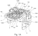
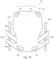
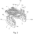
- FIGS 1A to 1E and Figure 2 illustrate an example of the surgical implant in accordance with the disclosed subject matter.
- the implant may be formed of any materials suitable for implantation into the body of a patient.
- the implant in accordance with the disclosed subject matter is at least partially encapsulated in a biocompatible material.
- the implant may be substantially encapsulated at least in one layer of a biocompatible polymer including at least one of silicone, phenyltrimethoxysilane (PTMS), polymethyl methacrylate (PMMA), parylene C, polyimide, liquid polyimide, laminated polyimide, epoxy, polyether ether ketone (PEEK), liquid crystal polymer (LCP), KAPTON, or combinations thereof.
- the implant may be encapsulated at least in one layer of a biocompatible polymer, and include one or more additional layer covering portions thereof.
- the implant may include ceramic material, thermoplastic material such as ULTEM, or other compatible materials.
- the surgical implant generally designated 100, comprises a substantially planar central body portion 120 having a top side 122 and a bottom side 124; two adjustable wing portions 132A and 132B; connecting members 134A and 134B (in the illustrated example, each connecting member comprising two elements 136A and 136B as will be further described hereinafter).
- the connecting members extending respectively from opposite sides of the central body portion 120, each of the connecting members is configured for flexibly connecting each one of the two wing portions 132A and 132B to said central body portion 120 at opposite sides thereof.
- the implant further comprises electronic components configured to stimulate a nerve when implanted in a subject in a location that permits it to modulate a nerve (e.g. as seen in Fig. 3 ) as will be discussed, without being in a direct contact with the nerve to be modulated/stimulated.
- the implant unit 100 may be placed on a genioglossus muscle so as to neuromodulate a hypoglossal nerve, which at least partially may extend within the muscle.
- the surgical implant due to the structure of the surgical implant, its flexibility and the degrees of freedom of the connecting members and the wing portions, it allows for neuromodulation of nerve branches otherwise not accessible as these are either extending within the muscle tissue or are branched out such that only emitting of electrical filed over an area covering the respective branches of the nerve will permit neuromodulating of the nerve, such as the terminal branches of the hypoglossal nerve.
- implant may include an antenna a (seen e.g. in Figs 1A and 2 ) and associated electronic circuit and components mounted onto or integrated with central body portion (160, details not shown).
- the antenna a may include any suitable antenna known to those skilled in the art that may be configured to send and/or receive signals and power.
- the antenna may include any suitable size, shape, and/or configuration accommodated by the dimensions of the implant. The size, shape and/or configuration may be determined by the patient anatomy, the placement location of the implant unit, the amount of energy required to neuromodulate the nerve, etc.
- Suitable antennas may include, but are not limited to, a long-wire antenna, a patch antenna, a helical antenna, PCB antenna, etc.
- Implant may additionally include a plurality of field-generating implant electrodes generally designated e (e.g. Fig. 1 A , 1B , 2 ).
- the electrodes e may include any suitable shape and/or orientation on the implant unit so long as the electrodes may be configured to generate an electric field in the body of a patient.
- Implant electrodes may also include any suitable conductive material (e.g., copper, silver, gold, platinum, iridium, platinum-iridium, platinum-gold, conductive polymers, etc.) or combinations of conductive (and/or noble metals) materials.
- the electrodes may include short line electrodes, circular electrodes, and/or circular pairs of electrodes.
- electrodes e may be located on the wing portions connected by connecting wires W to the electronic components and the antenna on the central body portion.
- the electrodes e may be located on any portion of wing portions.
- the connecting wires are configured to extend through the connecting members and are sized and shaped to be encapsulated therein.
- the wires W extend in designated channels.
- the wires may extend in designated reinforced channels.
- the connecting members are provided with designated channels (not shown) configured to retain the connecting wires in place and further facilitating the flexibility of the connecting members without braking or damaging the wires and their respective connections to the components on the central body portion and the respective electrode.
- the implant may further include circuit components 160 and any other required components facilitating the antenna to receive the energy and transmitting this energy for the electrodes to emit the electric filed to the nerves.
- the implant does not comprise a power source.
- the implant in the illustrated example is activated externally. It will be appreciated that other means of activating the implant can be envisioned, either externally or internally.
- the implant unit can be activate using wifi, RF, IR or Bluetooth technologies.
- Implant electrodes e may be spaced apart by about a distance of about 0.2 mm to 40 mm. In other embodiments, the electrodes may be spaced apart by a distance of approximately up to 12 mm. In accordance with yet an example, the distance may be approximately 0.5-7 mm measured between the internal edges of the electrodes.
- implant may include a protective coating that encapsulates the implant 170.
- the protective coating may be made from a flexible material to enable bending thereof, such as silicone. The encapsulation material of the protective coating may also resist humidity penetration and protect against corrosion.
- the surgical implant is substantially sealed and impervious to fluid.
- substantially sealed implant refers to the condition of having a sufficiently low unintended leakage and permeation rate under given fluid flow or pressure conditions.
- first pair of electrodes and the second pair of electrodes may be partially covered at their periphery with the encapsulating material, having at least a portion thereof exposed however sealing the implant such that no fluid will enter or exit through the seal surrounding the open window of the electrodes.
- first pair of electrodes and the second pair of electrodes are partially embedded within the encapsulating material and comprise an outer layer of encapsulating material extending thereover and leaving at least a portion thereof exposed to the environment.
- each one of the two connecting members is constituted by two parallelly extending arched elongated elements 136A and 136B, each extending at an angle and hingedly from the central body 120, such that the connecting members are integrally formed with and extend from the central body portion, allowing for at least one degree of freedom, as will be discussed.
- a connecting may be through a hinge which may be a living hinge, integral hinge, segmented hinge, etc.
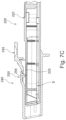
- the arched elongated segments extend from the side edge 125 and project above the top side 122 of the central body portion 120, as best seen in Fig. 1C , with the wing portions 132A and 132B, each integrally formed with and extending from the opposite ends of the elongated segments.
- each connecting member comprises two separate segments, in accordance with the disclosed subject matter, the connecting member may be a single segment. In accordance with another example, the two separate members may be connected with a connecting layer therebetween, either continuously, leaving no opening between the arched elongated segments, or with a non-continuous, layer, interconnecting the segments.
- each one of the two wing portions is integrally articulated to the respective elongated segments (extension members) extending between the central body portion and the two wing portions.
- the connecting member may be a flexible element configured to deform in at least one direction.
- the connecting member can be of a unitary thickness or as exemplified and best seen in Fig. 1C of thickness decreasing from the portion closest to the area of connection with the central body designated H to thickness designated h at the portion closer to the wing portions.
- the decrease in thickness can be gradual (as shown) or alternatively provided in segments. Such decrease in thickness provides for flexibility of the connecting members and allows for degrees of freedom both to the connecting members and the movement of the wing portions.
- the connecting members are configured to endure strain, particularly due to being bent, folded, or stretched, without breaking or suffering permanent injury. "Flexible" as used herein may or may not include the further properties of being resilient or elastic. Deformation could refer to at least one parameter change, e.g. change of length, thickness etc. in a pre-specified space.
- the connecting members allow several degrees of freedom to the two wing portions as best illustrated in Figs. 1B and 1C .
- the connecting members are configured with flexibility along the length thereof and at least at points designated C, B and A, where point C designates the section at the connection of the elongated segment to the central body portion, point B designates the segment at around the center of the arch of the elongated member and point A designates the segment integrally connecting the elongated members to the wing portions.
- point C designates the section at the connection of the elongated segment to the central body portion
- point B designates the segment at around the center of the arch of the elongated member
- point A designates the segment integrally connecting the elongated members to the wing portions.
- the elongated segment is allowed to deform and open the arch and move the wing portion at an angle ⁇ which can be between 0 degrees and up to 180 degrees.
- the angle ⁇ can extend between -90 (e.g.
- the wing portion can pivot at point A at angle ⁇ which can be between 0 degrees to about 100 degrees. In other examples, the angle can extend between -90 (e.g. towards the bottom side 124) to 100 degrees, or as illustrated up to 25 degrees. It will be appreciated that while the angular displacement has been shown separately for each of the points a combination of displacement is allowed and the wing portions can be angled in combination with the angular or other deformation of the connecting members. In accordance with disclosed subject matter and illustrated example, 0 degrees is the resting position of the element which has the degree of freedom to change position(s).
- the wing portions can be displaced in the direction of arrow X (e.g. horizontally), arrow Z (vertically) or arrow Y (angularly, e.g. inwards the central portion or outwardly therefrom, where the wing portions can flex towards or away from each other).
- arrow X e.g. horizontally
- arrow Z vertically
- arrow Y angularly, e.g. inwards the central portion or outwardly therefrom, where the wing portions can flex towards or away from each other.
- Such flexibility along multitude of dimensions allow positioning of the implant and in particular its wing portions over the treated muscle, in a saddle like position and conform to the dimensions of the muscle, which may be different from subject to subject.
- the disposition of the wing portion is further defined by angle ⁇ which provide for an angle between the edge 137 of the wing and the horizontal plane extending through the central body portion.
- the angle ⁇ can be between about 0 degrees to 10 degrees, and in the illustrated example is between 3
- the surgical implant may be formed from a unitary elastomeric material.
- the implant may be provided with anchoring arrangements.
- the anchoring arrangement is in the form of suturing holes (e.g. 152, 155).
- the implant may be provided with anchoring elements made of a material configured to withstand the forces acting on the implant and the sutures, e.g. during the tongue movement.
- a material can be e.g. a PEEK, ceramic, titanium etc.
- the suturing holes 152 can be provided at the wing portions at the desired location.
- other anchoring elements can be provided at the central body portion, e.g. adjacent the edges thereof as seen in Fig, 1D designated as 154.
- the central body portion comprises four such holes, only few or none of these can be provided.
- the positioning of the suture holes on the wing portions as illustrated in the accompanying drawings are for illustration purposes only and other shapes, configurations and positions thereof are envisioned.
- Other types of anchoring arrangements are envisioned, such as adhesives, staples etc, as disclosed herein.
- the central body portion can further be provided with a load bearing reinforcing structure 158, internally disposed, and configured to provide structural rigidity to the central body portion.
- the reinforcing structure can be resilient and allow for a degree of flexibility to the central body portion when force is applied thereto in the direction of arrow E, allowing at least a portion of the central body portion to flex e.g. as seen in Fig. 1B .
- the reinforcing structure in the illustrated example is provided through the central body and provides for a walled structured 156 to surround the electronics 160 and also longitudinal ribs 158 as seen e.g. in Fig. 1A .
- the reinforcing structure may have a different structure, e.g. crossed ribs to form a net like structure, a spiral, e.g. interconnected stips, etc. to provide for the same function of reinforcement and substantial exposure of the antenna a and the electronic parts.
- the implant may further comprise a surgical mesh, e.g. polymeric mesh, provided at least over a portion thereof.
- a surgical mesh may be of any suitable material.
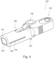
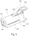
- an implant unit activation device illustrated in Figures 4 to 7C and generally designated 200 comprises a main body 220 comprising an implant activator and an axially displaceable retractor 240 configured to displace relative the main body.
- the implant activator comprises an antenna, a power source and associated circuitry (not shown) and being configured to wirelessly transfer energy from the power source to an implant unit (e.g. surgical implant 100) during implantation of the implant unit into the body of a subject to cause stimulation of at least one nerve in the body of the subject during the implantation procedure.
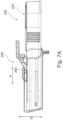
- the axial displacement of the retractor 240 allows adjusting of the degree of energy received by the implant unit.
- the activation device is configured to deliver energy to the implant unit with the retractor allowing to displace or more particularly retract the activation unit in the direction of arrow P (seen in Fig. 7A ) from the implant so as to control the amount of energy received by the implant unit as a function of distance at which it is delivered thereto.
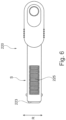
- the axis of displacement may comprise e.g. displacement along axis Q and ⁇ or R (e.g. as shown in Figs. 6 and 7A ).
- the retractor 240 is in this example a sleeve like member configured to controllably slide over the main shaft S of the activation device main body.
- the sleeve like member defines a hollowed and axially extending interior which securably mounts over the shaft of the main body.
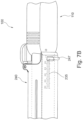
- the sleeve like member is provided with a release lever 245 and engagement mechanism 250, such that the engagement mechanism is configured to selectively engage the corresponding engaging members 225 on the shaft of the main body.
- the shaft is provided with toothed surface 225 and the inner side of the sleeve is provided with the engagement mechanism 255 constituted by a protrusion configured to engage the toothed surface to lock thereagainst.
- the main body shaft may be provided with indicia 235 allowing the user to determine the location at which it is desired to lock the sleeve against the shaft.
- the shaft is provided with a protrusion 229 which when aligned with the sleeve extends slidable in a slit 243 in the sleeve which in the example extends at two opposite sides of the sleeve as seen in Fig. 5 .
- a protrusion 229 which when aligned with the sleeve extends slidable in a slit 243 in the sleeve which in the example extends at two opposite sides of the sleeve as seen in Fig. 5 .
- other configurations are envisioned that will allow the main body of the activation device to be distanced from the implant unit keeping the device at the predetermined position with respect to the implant unit.
- the sleeve can further be provided with a support and gripping element 247 to allow the user to grip the sleeve, while activating the lever 245 to release the engagement of the mechanism 255 and retracting the shaft body through the sleeve to distance its end portion 223 from the opening 241 in the sleeve.
- the edge of the device 200 is angled to enable line of sight during use and for ergonomic considerations.
- the amount of energy or power level is determined by the axial movement of the retractor
- other examples include a screw on sleeve, partial elements extending from the shaft and configured to distance the edge of the shaft from the point of contact with the implant device.
- the amount and level of energy may be controlled directly through the device, without adjusting the distance between the shaft edge relative the implant device.
- An exemplary method of positioning and activating a neurostimulation implant device e.g. surgical implant 100 in accordance with the disclosed subject matter is provided.
- the method in accordance with the disclosed subject matter comprises: providing the implant and positioning it over the tissue of the subject, e.g. the genioglossus muscle.
- an implant unit activation device comprising: a main body comprising an implant activator having a power source, a second antenna configured to provide a signal to the first antenna and an axially displaceable adaptor ⁇ retractor associated with the implant activator, the implant activator configured to wirelessly transfer energy from a power source to the implant during implantation to cause modulation of at least one nerve in the body of the subject; and wherein the axial displacement (e.g. retraction) of the adaptor from at least a first position to at least a second position allows adjusting of the degree of energy received by the implant unit.
- next step comprises identifying the stimulation threshold by determining a degree of nerve modulation response for each of the at least first pair of electrodes and a second pair of electrodes by positioning said first pair of electrodes at an estimated implant location proximal to the nerve and selectively displacing the second antenna to deliver a first amount of power and a second amount of power required to obtain a stimulation threshold in at least the first pair of electrodes based on one or more patient signals;
- the implant may be configured for treatment of obstructive sleep apnea and the location of implantation may be in the vicinity of the hypoglossal nerve.
- the neurostimulation device may be configured to modulate at least one branch of the hypoglossal nerves.
- the second amount may be greater or equal to the first amount of power.
- the second amount may be equal to or less relative the first amount of power.
Landscapes
- Health & Medical Sciences (AREA)
- Animal Behavior & Ethology (AREA)
- Public Health (AREA)
- Engineering & Computer Science (AREA)
- Biomedical Technology (AREA)
- Nuclear Medicine, Radiotherapy & Molecular Imaging (AREA)
- Radiology & Medical Imaging (AREA)
- Life Sciences & Earth Sciences (AREA)
- General Health & Medical Sciences (AREA)
- Veterinary Medicine (AREA)
- Pulmonology (AREA)
- Physiology (AREA)
- Neurology (AREA)
- Neurosurgery (AREA)
- Cardiology (AREA)
- Heart & Thoracic Surgery (AREA)
- Prostheses (AREA)
- Electrotherapy Devices (AREA)
Applications Claiming Priority (2)
| Application Number | Priority Date | Filing Date | Title |
|---|---|---|---|
| US201762464917P | 2017-02-28 | 2017-02-28 | |
| PCT/EP2018/054913 WO2018158305A1 (en) | 2017-02-28 | 2018-02-28 | Surgical implant system |
Publications (2)
| Publication Number | Publication Date |
|---|---|
| EP3589358A1 EP3589358A1 (en) | 2020-01-08 |
| EP3589358B1 true EP3589358B1 (en) | 2025-06-04 |
Family
ID=61837720
Family Applications (1)
| Application Number | Title | Priority Date | Filing Date |
|---|---|---|---|
| EP18714702.0A Active EP3589358B1 (en) | 2017-02-28 | 2018-02-28 | Surgical implant system |
Country Status (8)
| Country | Link |
|---|---|
| US (1) | US11707623B2 (enExample) |
| EP (1) | EP3589358B1 (enExample) |
| JP (1) | JP7248581B2 (enExample) |
| CN (1) | CN110325243B (enExample) |
| AU (1) | AU2018227019B2 (enExample) |
| CA (1) | CA3054180A1 (enExample) |
| IL (1) | IL268887B2 (enExample) |
| WO (1) | WO2018158305A1 (enExample) |
Families Citing this family (3)
| Publication number | Priority date | Publication date | Assignee | Title |
|---|---|---|---|---|
| NL2019598B1 (en) * | 2017-09-21 | 2019-03-28 | Tacx Roerend En Onroerend Goed B V | Bicycle trainer and method of its operation |
| IL268936A (en) | 2019-08-26 | 2021-03-01 | Nyxoah SA | Method and process for placing and fixing a surgical implant |
| AU2020468179B2 (en) * | 2020-09-18 | 2025-02-13 | Nyxoah SA | Pair of intelligent electric conductors |
Citations (1)
| Publication number | Priority date | Publication date | Assignee | Title |
|---|---|---|---|---|
| US9504839B2 (en) * | 2013-07-15 | 2016-11-29 | Boston Scientific Neuromodulation Corporation | Tension clamp side loading lead anchor and methods and systems using the lead anchor |
Family Cites Families (83)
| Publication number | Priority date | Publication date | Assignee | Title |
|---|---|---|---|---|
| US2125008A (en) | 1935-10-05 | 1938-07-26 | William M Scholl | Medicated pad |
| US4370984A (en) | 1979-04-30 | 1983-02-01 | Ndm Corporation | X-Ray transparent medical electrode |
| USD272943S (en) | 1981-06-22 | 1984-03-06 | Stone Robert D | Electrode for biomedical signals |
| US4856499A (en) | 1988-04-11 | 1989-08-15 | Assist Research Corp. | Erection device |
| US5261400A (en) * | 1992-02-12 | 1993-11-16 | Medtronic, Inc. | Defibrillator employing transvenous and subcutaneous electrodes and method of use |
| USD349958S (en) | 1992-07-24 | 1994-08-23 | Bioject Inc. | Needleless injector |
| US5406945A (en) | 1993-05-24 | 1995-04-18 | Ndm Acquisition Corp. | Biomedical electrode having a secured one-piece conductive terminal |
| US5645586A (en) * | 1994-07-08 | 1997-07-08 | Ventritex, Inc. | Conforming implantable defibrillator |
| USD372787S (en) | 1995-01-31 | 1996-08-13 | Dozier Glenda S | Bandage |
| US5538500A (en) | 1995-02-08 | 1996-07-23 | Peterson; Donald A. | Postoperative wound dressing |
| JP2974959B2 (ja) | 1996-03-01 | 1999-11-10 | テクナ電子工業株式会社 | 睡眠時無呼吸デ−タ収録装置 |
| US5995874A (en) | 1998-02-09 | 1999-11-30 | Dew Engineering And Development Limited | Transcutaneous energy transfer device |
| US6031746A (en) | 1998-09-04 | 2000-02-29 | General Electric Company | Switching amplifier for generating continuous arbitrary waveforms for magnetic resonance imaging coils |
| USD430674S (en) | 2000-01-07 | 2000-09-05 | 3M Innovative Properties Company | Adhesive bandage |
| GB0011202D0 (en) | 2000-05-09 | 2000-06-28 | Kci Licensing Inc | Abdominal wound dressing |
| US6850803B1 (en) * | 2000-06-16 | 2005-02-01 | Medtronic, Inc. | Implantable medical device with a recharging coil magnetic shield |
| US6549071B1 (en) | 2000-09-12 | 2003-04-15 | Silicon Laboratories, Inc. | Power amplifier circuitry and method using an inductance coupled to power amplifier switching devices |
| US7052483B2 (en) | 2000-12-19 | 2006-05-30 | Animas Corporation | Transcutaneous inserter for low-profile infusion sets |
| US7151914B2 (en) | 2001-08-21 | 2006-12-19 | Medtronic, Inc. | Transmitter system for wireless communication with implanted devices |
| US20040010233A1 (en) | 2002-04-16 | 2004-01-15 | Birger Hjertman | System and a method for modification of a device and a device suitable for modification |
| USD477085S1 (en) | 2002-10-07 | 2003-07-08 | Robert Michael Sanfilippo | Medical electrode with an off-set snaptab |
| US7976519B2 (en) | 2002-12-31 | 2011-07-12 | Kci Licensing, Inc. | Externally-applied patient interface system and method |
| USD516212S1 (en) | 2003-05-13 | 2006-02-28 | Atos Medical Ab | Tracheostoma plaster device |
| US7233137B2 (en) | 2003-09-30 | 2007-06-19 | Sharp Kabushiki Kaisha | Power supply system |
| CN101146494B (zh) * | 2005-03-21 | 2012-02-01 | 凯福恩公司 | 带有可展开翼部的棘突间植入物 |
| USD655807S1 (en) | 2005-12-09 | 2012-03-13 | Unomedical A/S | Medical device |
| US7610100B2 (en) * | 2005-12-30 | 2009-10-27 | Boston Scientific Neuromodulation Corporation | Methods and systems for treating osteoarthritis |
| CA120177S (en) | 2006-10-30 | 2009-06-01 | Sanofi Aventis Deutschland | Medical injector |
| US7772582B2 (en) | 2007-07-11 | 2010-08-10 | International Business Machines Corporation | Four-terminal reconfigurable devices |
| EP3954433A1 (en) | 2007-10-16 | 2022-02-16 | Implantica Patent Ltd. | A method and system for supplying energy to a medical device |
| NZ565234A (en) | 2008-01-18 | 2010-11-26 | Telemetry Res Ltd | Selectable resonant frequency transcutaneous energy transfer system |
| WO2009114671A1 (en) | 2008-03-13 | 2009-09-17 | Access Business Group International Llc | Inductive power supply system with multiple coil primary |
| US8487480B1 (en) | 2008-09-27 | 2013-07-16 | Witricity Corporation | Wireless energy transfer resonator kit |
| US9396867B2 (en) | 2008-09-27 | 2016-07-19 | Witricity Corporation | Integrated resonator-shield structures |
| US9515494B2 (en) | 2008-09-27 | 2016-12-06 | Witricity Corporation | Wireless power system including impedance matching network |
| US20120235504A1 (en) | 2008-09-27 | 2012-09-20 | Kesler Morris P | Tunable wireless energy transfer for sensors |
| WO2010059097A1 (en) | 2008-11-21 | 2010-05-27 | Milux Holding S.A. | System, method and apparatus f or supplying energy to an implantable medical device |
| JP2010252468A (ja) | 2009-04-14 | 2010-11-04 | Sony Corp | 送電装置および方法、受電装置および方法、並びに、電力伝送システム |
| US9044588B2 (en) | 2009-04-16 | 2015-06-02 | Cochlear Limited | Reference electrode apparatus and method for neurostimulation implants |
| WO2011008165A1 (en) | 2009-07-17 | 2011-01-20 | Milux Holding S.A. | An improved medical system comprising implants |
| EP2461862A4 (en) * | 2009-08-06 | 2013-02-20 | Giancarlo Barolat | SYSTEM AND METHOD FOR STIMULATION OF POSTERIOR TIBIAL NERVE AND / OR OTHER NERVE |
| US9950166B2 (en) * | 2009-10-20 | 2018-04-24 | Nyxoah SA | Acred implant unit for modulation of nerves |
| WO2011074082A1 (ja) | 2009-12-16 | 2011-06-23 | 富士通株式会社 | 磁界共鳴送電装置、及び、磁界共鳴受電装置 |
| US8721661B2 (en) * | 2010-04-14 | 2014-05-13 | Medtronic, Inc. | Strain relief apparatus for use with implantable medical lead |
| US20120089081A1 (en) | 2010-10-12 | 2012-04-12 | Wahng Chao Uei | Piezoelectric element driver |
| CA141113S (en) | 2010-12-23 | 2012-01-23 | Profibrix Bv | Dispenser for pharmaceutical powder formulations |
| DE102011005519A1 (de) | 2011-03-14 | 2012-09-20 | Maschinenfabrik Gustav Eirich Gmbh & Co. Kg | Verfahren zum Granulieren oder Agglomerieren sowie Werkzeug hierfür |
| EP2701783B1 (en) | 2011-04-28 | 2021-03-24 | Sanofi-Aventis Deutschland GmbH | Connection for medical device |
| US8401664B2 (en) | 2011-04-29 | 2013-03-19 | Cyberonics, Inc. | System and method for charging a power cell in an implantable medical device |
| USD735322S1 (en) | 2011-05-11 | 2015-07-28 | Sanofi-Aventis Deutschland Gmbh | Injection device |
| CA2850434C (en) | 2011-09-30 | 2021-03-16 | Adi Mashiach | Apparatus and methods for implant coupling indication |
| US9818530B2 (en) | 2012-01-17 | 2017-11-14 | Texas Instruments Incorporated | Adaptive wireless power transfer system and method |
| JP2013223409A (ja) | 2012-04-19 | 2013-10-28 | Sony Corp | 送電装置、非接触電力伝送システムおよび信号生成方法 |
| EP2845290B1 (en) | 2012-05-03 | 2018-08-29 | Powermat Technologies Ltd. | System and method for triggering power transfer across an inductive power coupling and non resonant transmission |
| AU346291S (en) | 2012-05-15 | 2013-01-09 | Smith & Nephew | Medical dressing |
| KR20150112923A (ko) * | 2012-07-26 | 2015-10-07 | 아디 매쉬아취 | 임플란트 디바이스와 외부 디바이스 간의 내부 공진 매칭 |
| US10052097B2 (en) | 2012-07-26 | 2018-08-21 | Nyxoah SA | Implant unit delivery tool |
| US9935498B2 (en) | 2012-09-25 | 2018-04-03 | Cyberonics, Inc. | Communication efficiency with an implantable medical device using a circulator and a backscatter signal |
| US9305700B2 (en) | 2012-10-04 | 2016-04-05 | Linear Technology Corporation | Auto resonant driver for wireless power transmitter sensing required transmit power for optimum efficiency |
| US10238875B2 (en) | 2012-12-19 | 2019-03-26 | Adi Mashiach | Systems and methods for hypertension control |
| US20140339910A1 (en) | 2013-05-15 | 2014-11-20 | Witricity Corporation | Device to device signaling in wireless energy transfer systems |
| CN105873637B (zh) * | 2013-06-17 | 2020-03-03 | 尼科索亚股份有限公司 | 在整个治疗周期上进行调节的动态修改 |
| USD764657S1 (en) | 2013-07-03 | 2016-08-23 | Unitract Syringe Pty Ltd | Automatic injector |
| USD755980S1 (en) | 2013-08-30 | 2016-05-10 | Mölnlycke Health Care Ab | Wound dressing |
| CN104578439B (zh) | 2013-10-21 | 2018-10-09 | 台达电子企业管理(上海)有限公司 | 用于无线充电线路的装置 |
| USD715928S1 (en) | 2013-10-28 | 2014-10-21 | Tidi Securement Products, Llc | Catheter anchor pad with release layer |
| US9294057B2 (en) | 2013-12-18 | 2016-03-22 | National Instruments Corporation | Efficient low noise high speed amplifier |
| US9895531B2 (en) | 2014-04-11 | 2018-02-20 | Pacesetter, Inc. | Protective patch for protecting the implant site of a trial neurostimulation lead |
| USD778451S1 (en) | 2014-05-13 | 2017-02-07 | Tdk Corporation | Conductive seal of a biomedical signal recorder |
| US9358384B2 (en) * | 2014-09-05 | 2016-06-07 | Advanced Neuromodulation Systems, Inc. | Implantable lead with flexible paddle electrode array |
| US10456497B2 (en) | 2014-09-10 | 2019-10-29 | C. R. Bard, Inc. | Protective dressing for skin-placed medical device |
| USD759828S1 (en) | 2014-09-18 | 2016-06-21 | Steven Riedle | Adhesive bandage |
| USD756513S1 (en) | 2014-11-13 | 2016-05-17 | Biomedical Enterprises, Inc. | Orthopedic implant insertion device |
| USD780311S1 (en) | 2014-11-20 | 2017-02-28 | Biomedical Enterprises, Inc. | Orthopedic implant |
| US20170007442A1 (en) | 2015-07-11 | 2017-01-12 | Thermal Fit, LLC | Intraoral Orthosis Device and Method for Manufacturing |
| USD777329S1 (en) | 2015-10-19 | 2017-01-24 | Nextremity Solutions, Inc. | Bone staple |
| USD773666S1 (en) | 2015-10-27 | 2016-12-06 | Biomedical Enterprises, Inc. | Orthopedic implant |
| USD773665S1 (en) | 2015-10-27 | 2016-12-06 | Biomedical Enterprises, Inc. | Orthopedic implant |
| USD819202S1 (en) | 2016-02-04 | 2018-05-29 | Atos Medical Ab | Heat and moisture exchanger base plate |
| USD790714S1 (en) | 2016-02-12 | 2017-06-27 | Kci Usa, Inc. | Medical dressing support frame with tab |
| USD866769S1 (en) | 2016-09-12 | 2019-11-12 | Nyxoah S.A. | Patch |
| CN106422063A (zh) * | 2016-11-23 | 2017-02-22 | 刘帆 | 一种简易电激止鼾方法及装置 |
| WO2018136493A1 (en) | 2017-01-17 | 2018-07-26 | Veressa Medical, Inc. | System for identifying a target medical device implant site |
-
2018
- 2018-02-28 US US16/488,141 patent/US11707623B2/en active Active
- 2018-02-28 AU AU2018227019A patent/AU2018227019B2/en active Active
- 2018-02-28 EP EP18714702.0A patent/EP3589358B1/en active Active
- 2018-02-28 IL IL268887A patent/IL268887B2/en unknown
- 2018-02-28 CN CN201880014151.9A patent/CN110325243B/zh active Active
- 2018-02-28 CA CA3054180A patent/CA3054180A1/en active Pending
- 2018-02-28 WO PCT/EP2018/054913 patent/WO2018158305A1/en not_active Ceased
- 2018-02-28 JP JP2019546279A patent/JP7248581B2/ja active Active
Patent Citations (1)
| Publication number | Priority date | Publication date | Assignee | Title |
|---|---|---|---|---|
| US9504839B2 (en) * | 2013-07-15 | 2016-11-29 | Boston Scientific Neuromodulation Corporation | Tension clamp side loading lead anchor and methods and systems using the lead anchor |
Also Published As
| Publication number | Publication date |
|---|---|
| CN110325243B (zh) | 2023-12-05 |
| EP3589358A1 (en) | 2020-01-08 |
| AU2018227019A1 (en) | 2019-10-17 |
| IL268887B2 (en) | 2023-11-01 |
| WO2018158305A1 (en) | 2018-09-07 |
| US20200001082A1 (en) | 2020-01-02 |
| CN110325243A (zh) | 2019-10-11 |
| IL268887B1 (en) | 2023-07-01 |
| US11707623B2 (en) | 2023-07-25 |
| JP7248581B2 (ja) | 2023-03-29 |
| CA3054180A1 (en) | 2018-09-07 |
| IL268887A (en) | 2019-10-31 |
| WO2018158305A9 (en) | 2019-07-18 |
| AU2018227019B2 (en) | 2023-07-20 |
| JP2020508759A (ja) | 2020-03-26 |
Similar Documents
| Publication | Publication Date | Title |
|---|---|---|
| US9486621B2 (en) | Implanting an electrode array against the spinal cord inside the dura for stimulating the spinal cord and treating pain | |
| US9427572B2 (en) | Implantable medical device with connector blocks | |
| CA2957962C (en) | Implantable lead affixation structure for nerve stimulation to alleviate bladder dysfunction and other indications | |
| US9026227B2 (en) | Anchor sleeve for implantable lead | |
| US8332044B2 (en) | Percutaneous access for neuromodulation procedures | |
| EP2101861B1 (en) | Attached implantable medical elongated members | |
| US20060173520A1 (en) | Implantable retention system and method | |
| EP3448496B1 (en) | Lead implant fixation mechanism | |
| US20190001122A1 (en) | Lead for neuromodulation | |
| EP3589358B1 (en) | Surgical implant system | |
| EP2456511B1 (en) | Electrode having erectable lead | |
| HK40013633A (en) | Surgical implant system | |
| HK40013633B (zh) | 外科植入系统 | |
| US20090030492A1 (en) | Nerve lead tie down with bearing |
Legal Events
| Date | Code | Title | Description |
|---|---|---|---|
| STAA | Information on the status of an ep patent application or granted ep patent |
Free format text: STATUS: UNKNOWN |
|
| STAA | Information on the status of an ep patent application or granted ep patent |
Free format text: STATUS: THE INTERNATIONAL PUBLICATION HAS BEEN MADE |
|
| PUAI | Public reference made under article 153(3) epc to a published international application that has entered the european phase |
Free format text: ORIGINAL CODE: 0009012 |
|
| STAA | Information on the status of an ep patent application or granted ep patent |
Free format text: STATUS: REQUEST FOR EXAMINATION WAS MADE |
|
| 17P | Request for examination filed |
Effective date: 20190924 |
|
| AK | Designated contracting states |
Kind code of ref document: A1 Designated state(s): AL AT BE BG CH CY CZ DE DK EE ES FI FR GB GR HR HU IE IS IT LI LT LU LV MC MK MT NL NO PL PT RO RS SE SI SK SM TR |
|
| AX | Request for extension of the european patent |
Extension state: BA ME |
|
| DAV | Request for validation of the european patent (deleted) | ||
| DAX | Request for extension of the european patent (deleted) | ||
| STAA | Information on the status of an ep patent application or granted ep patent |
Free format text: STATUS: EXAMINATION IS IN PROGRESS |
|
| 17Q | First examination report despatched |
Effective date: 20230510 |
|
| GRAP | Despatch of communication of intention to grant a patent |
Free format text: ORIGINAL CODE: EPIDOSNIGR1 |
|
| STAA | Information on the status of an ep patent application or granted ep patent |
Free format text: STATUS: GRANT OF PATENT IS INTENDED |
|
| INTG | Intention to grant announced |
Effective date: 20250306 |
|
| RAP3 | Party data changed (applicant data changed or rights of an application transferred) |
Owner name: NYXOAH S.A. |
|
| GRAS | Grant fee paid |
Free format text: ORIGINAL CODE: EPIDOSNIGR3 |
|
| GRAA | (expected) grant |
Free format text: ORIGINAL CODE: 0009210 |
|
| STAA | Information on the status of an ep patent application or granted ep patent |
Free format text: STATUS: THE PATENT HAS BEEN GRANTED |
|
| AK | Designated contracting states |
Kind code of ref document: B1 Designated state(s): AL AT BE BG CH CY CZ DE DK EE ES FI FR GB GR HR HU IE IS IT LI LT LU LV MC MK MT NL NO PL PT RO RS SE SI SK SM TR |
|
| REG | Reference to a national code |
Ref country code: GB Ref legal event code: FG4D |
|
| REG | Reference to a national code |
Ref country code: CH Ref legal event code: EP |
|
| REG | Reference to a national code |
Ref country code: DE Ref legal event code: R096 Ref document number: 602018082380 Country of ref document: DE |
|
| REG | Reference to a national code |
Ref country code: IE Ref legal event code: FG4D |
|
| REG | Reference to a national code |
Ref country code: NL Ref legal event code: FP |
|
| PG25 | Lapsed in a contracting state [announced via postgrant information from national office to epo] |
Ref country code: FI Free format text: LAPSE BECAUSE OF FAILURE TO SUBMIT A TRANSLATION OF THE DESCRIPTION OR TO PAY THE FEE WITHIN THE PRESCRIBED TIME-LIMIT Effective date: 20250604 Ref country code: ES Free format text: LAPSE BECAUSE OF FAILURE TO SUBMIT A TRANSLATION OF THE DESCRIPTION OR TO PAY THE FEE WITHIN THE PRESCRIBED TIME-LIMIT Effective date: 20250604 |
|
| REG | Reference to a national code |
Ref country code: LT Ref legal event code: MG9D |
|
| PG25 | Lapsed in a contracting state [announced via postgrant information from national office to epo] |
Ref country code: NO Free format text: LAPSE BECAUSE OF FAILURE TO SUBMIT A TRANSLATION OF THE DESCRIPTION OR TO PAY THE FEE WITHIN THE PRESCRIBED TIME-LIMIT Effective date: 20250904 Ref country code: GR Free format text: LAPSE BECAUSE OF FAILURE TO SUBMIT A TRANSLATION OF THE DESCRIPTION OR TO PAY THE FEE WITHIN THE PRESCRIBED TIME-LIMIT Effective date: 20250905 |
|
| PG25 | Lapsed in a contracting state [announced via postgrant information from national office to epo] |
Ref country code: PL Free format text: LAPSE BECAUSE OF FAILURE TO SUBMIT A TRANSLATION OF THE DESCRIPTION OR TO PAY THE FEE WITHIN THE PRESCRIBED TIME-LIMIT Effective date: 20250604 |
|
| PG25 | Lapsed in a contracting state [announced via postgrant information from national office to epo] |
Ref country code: BG Free format text: LAPSE BECAUSE OF FAILURE TO SUBMIT A TRANSLATION OF THE DESCRIPTION OR TO PAY THE FEE WITHIN THE PRESCRIBED TIME-LIMIT Effective date: 20250604 |
|
| PG25 | Lapsed in a contracting state [announced via postgrant information from national office to epo] |
Ref country code: HR Free format text: LAPSE BECAUSE OF FAILURE TO SUBMIT A TRANSLATION OF THE DESCRIPTION OR TO PAY THE FEE WITHIN THE PRESCRIBED TIME-LIMIT Effective date: 20250604 |
|
| PG25 | Lapsed in a contracting state [announced via postgrant information from national office to epo] |
Ref country code: RS Free format text: LAPSE BECAUSE OF FAILURE TO SUBMIT A TRANSLATION OF THE DESCRIPTION OR TO PAY THE FEE WITHIN THE PRESCRIBED TIME-LIMIT Effective date: 20250904 |
|
| PG25 | Lapsed in a contracting state [announced via postgrant information from national office to epo] |
Ref country code: LV Free format text: LAPSE BECAUSE OF FAILURE TO SUBMIT A TRANSLATION OF THE DESCRIPTION OR TO PAY THE FEE WITHIN THE PRESCRIBED TIME-LIMIT Effective date: 20250604 |
|
| PG25 | Lapsed in a contracting state [announced via postgrant information from national office to epo] |
Ref country code: PT Free format text: LAPSE BECAUSE OF FAILURE TO SUBMIT A TRANSLATION OF THE DESCRIPTION OR TO PAY THE FEE WITHIN THE PRESCRIBED TIME-LIMIT Effective date: 20251006 |