EP3589083B1 - Systems for forming and maintaining a high performance frc - Google Patents
Systems for forming and maintaining a high performance frc Download PDFInfo
- Publication number
- EP3589083B1 EP3589083B1 EP19187386.8A EP19187386A EP3589083B1 EP 3589083 B1 EP3589083 B1 EP 3589083B1 EP 19187386 A EP19187386 A EP 19187386A EP 3589083 B1 EP3589083 B1 EP 3589083B1
- Authority
- EP
- European Patent Office
- Prior art keywords
- frc
- plasma
- confinement
- confinement chamber
- formation
- Prior art date
- Legal status (The legal status is an assumption and is not a legal conclusion. Google has not performed a legal analysis and makes no representation as to the accuracy of the status listed.)
- Active
Links
Images


Classifications
-
- G—PHYSICS
- G21—NUCLEAR PHYSICS; NUCLEAR ENGINEERING
- G21B—FUSION REACTORS
- G21B1/00—Thermonuclear fusion reactors
- G21B1/05—Thermonuclear fusion reactors with magnetic or electric plasma confinement
- G21B1/052—Thermonuclear fusion reactors with magnetic or electric plasma confinement reversed field configuration
-
- H—ELECTRICITY
- H05—ELECTRIC TECHNIQUES NOT OTHERWISE PROVIDED FOR
- H05H—PLASMA TECHNIQUE; PRODUCTION OF ACCELERATED ELECTRICALLY-CHARGED PARTICLES OR OF NEUTRONS; PRODUCTION OR ACCELERATION OF NEUTRAL MOLECULAR OR ATOMIC BEAMS
- H05H1/00—Generating plasma; Handling plasma
- H05H1/02—Arrangements for confining plasma by electric or magnetic fields; Arrangements for heating plasma
- H05H1/04—Arrangements for confining plasma by electric or magnetic fields; Arrangements for heating plasma using magnetic fields substantially generated by the discharge in the plasma
- H05H1/08—Theta pinch devices, e.g. SCYLLA
-
- H—ELECTRICITY
- H05—ELECTRIC TECHNIQUES NOT OTHERWISE PROVIDED FOR
- H05H—PLASMA TECHNIQUE; PRODUCTION OF ACCELERATED ELECTRICALLY-CHARGED PARTICLES OR OF NEUTRONS; PRODUCTION OR ACCELERATION OF NEUTRAL MOLECULAR OR ATOMIC BEAMS
- H05H1/00—Generating plasma; Handling plasma
- H05H1/02—Arrangements for confining plasma by electric or magnetic fields; Arrangements for heating plasma
- H05H1/10—Arrangements for confining plasma by electric or magnetic fields; Arrangements for heating plasma using externally-applied magnetic fields only, e.g. Q-machines, Yin-Yang, base-ball
- H05H1/14—Arrangements for confining plasma by electric or magnetic fields; Arrangements for heating plasma using externally-applied magnetic fields only, e.g. Q-machines, Yin-Yang, base-ball wherein the containment vessel is straight and has magnetic mirrors
-
- H—ELECTRICITY
- H05—ELECTRIC TECHNIQUES NOT OTHERWISE PROVIDED FOR
- H05H—PLASMA TECHNIQUE; PRODUCTION OF ACCELERATED ELECTRICALLY-CHARGED PARTICLES OR OF NEUTRONS; PRODUCTION OR ACCELERATION OF NEUTRAL MOLECULAR OR ATOMIC BEAMS
- H05H1/00—Generating plasma; Handling plasma
- H05H1/02—Arrangements for confining plasma by electric or magnetic fields; Arrangements for heating plasma
- H05H1/16—Arrangements for confining plasma by electric or magnetic fields; Arrangements for heating plasma using externally-applied electric and magnetic fields
-
- H—ELECTRICITY
- H05—ELECTRIC TECHNIQUES NOT OTHERWISE PROVIDED FOR
- H05H—PLASMA TECHNIQUE; PRODUCTION OF ACCELERATED ELECTRICALLY-CHARGED PARTICLES OR OF NEUTRONS; PRODUCTION OR ACCELERATION OF NEUTRAL MOLECULAR OR ATOMIC BEAMS
- H05H3/00—Production or acceleration of neutral particle beams, e.g. molecular or atomic beams
-
- Y—GENERAL TAGGING OF NEW TECHNOLOGICAL DEVELOPMENTS; GENERAL TAGGING OF CROSS-SECTIONAL TECHNOLOGIES SPANNING OVER SEVERAL SECTIONS OF THE IPC; TECHNICAL SUBJECTS COVERED BY FORMER USPC CROSS-REFERENCE ART COLLECTIONS [XRACs] AND DIGESTS
- Y02—TECHNOLOGIES OR APPLICATIONS FOR MITIGATION OR ADAPTATION AGAINST CLIMATE CHANGE
- Y02E—REDUCTION OF GREENHOUSE GAS [GHG] EMISSIONS, RELATED TO ENERGY GENERATION, TRANSMISSION OR DISTRIBUTION
- Y02E30/00—Energy generation of nuclear origin
- Y02E30/10—Nuclear fusion reactors
Definitions
- the embodiments described herein relate generally to magnetic plasma confinement systems and, more particularly, to systems that facilitate forming and maintaining Field Reversed Configurations with superior stability as well as particle, energy and flux confinement.
- the Field Reversed Configuration belongs to the class of magnetic plasma confinement topologies known as compact toroids (CT). It exhibits predominantly poloidal magnetic fields and possesses zero or small self-generated toroidal fields (see M. Tuszewski, Nucl. Fusion 28, 2033 (1988 )).
- CT Compact toroids
- the attractions of such a configuration are its simple geometry for ease of construction and maintenance, a natural unrestricted divertor for facilitating energy extraction and ash removal, and very high ⁇ ( ⁇ is the ratio of the average plasma pressure to the average magnetic field pressure inside the FRC), i.e ., high power density.
- ⁇ is the ratio of the average plasma pressure to the average magnetic field pressure inside the FRC
- the high ⁇ nature is advantageous for economic operation and for the use of advanced, aneutronic fuels such as D-He 3 and p-B 11 .
- the traditional method of forming an FRC uses the field-reversed ⁇ -pinch technology, producing hot, high-density plasmas (see A. L. Hoffman and J. T. Slough, Nucl. Fusion 33, 27 (1993 )).
- a variation on this is the translation-trapping method in which the plasma created in a theta-pinch "source” is more-or-less immediately ejected out one end into a confinement chamber. The translating plasmoid is then trapped between two strong mirrors at the ends of the chamber (see, for instance, H. Himura, S. Okada, S. Sugimoto, and S. Goto, Phys. Plasmas 2, 191 (1995 )).
- FRCs have proved to be extremely robust, resilient to dynamic formation, translation, and violent capture events. Moreover, they show a tendency to assume a preferred plasma state (see e.g. H. Y. Guo, A. L. Hoffman, K. E. Miller, and L. C. Steinhauer, Phys. Rev. Lett. 92, 245001 (2004 )).
- FRCs consist of a torus of closed field lines inside a separatrix, and of an annular edge layer on the open field lines just outside the separatrix. The edge layer coalesces into jets beyond the FRC length, providing a natural divertor.
- the FRC topology coincides with that of a Field-Reversed-Mirror plasma.
- the FRC plasma has a ⁇ of about 10.
- the inherent low internal magnetic field provides for a certain indigenous kinetic particle population, i.e. particles with large larmor radii, comparable to the FRC minor radius. It is these strong kinetic effects that appear to at least partially contribute to the gross stability of past and present FRCs, such as those produced in the collision-merging experiment.
- Typical past FRC experiments have been dominated by convective losses with energy confinement largely determined by particle transport. Particles diffuse primarily radially out of the separatrix volume, and are then lost axially in the edge layer. Accordingly, FRC confinement depends on the properties of both closed and open field line regions.
- the particle diffusion time out of the separatrix scales as ⁇ ⁇ a 2 /D ⁇ (a ⁇ r s /4, where r s is the central separatrix radius), and D ⁇ is a characteristic FRC diffusivity, such as D ⁇ ⁇ 12.5 ⁇ ie , with ⁇ ie representing the ion gyroradius, evaluated at an externally applied magnetic field.
- the edge layer particle confinement time ⁇ ll is essentially an axial transit time in past FRC experiments. In steady-state, the balance between radial and axial particle losses yields a separatrix density gradient length ⁇ ⁇ (D ⁇ ll ) 1/2 .
- the FRC particle confinement time scales as ( ⁇ ⁇ ) 1/2 for past FRCs that have substantial density at the separatrix (see e.g. M. TUSZEWSKI, "Field Reversed Configurations," Nucl. Fusion 28, 2033 (1988 )).
- WO2013/074666-A2 discloses an FRC system having a central confinement vessel surrounded by two diametrically opposed reversed-field- theta-pinch formation sections and, beyond the formation sections, two divertor chambers to control neutral density and impurity contamination.
- a magnetic system having a series of quasi-dc coils is axially positioned along the FRC system components, quasi-dc mirror coils between the confinement chamber and the adjacent formation sections, and mirror plugs between the formation sections and the divertors.
- the formation sections include modular pulsed power formation systems that enable FRCs to be formed in-situ and then accelerated and injected (static formation) or formed and accelerated simultaneously (dynamic formation).
- the FRC system further includes neutral atom beam injectors, a pellet injector, gettering systems, axial plasma guns and flux surface biasing electrodes.
- ROGER RAMAN "Fuelling Requirements for Advanced Tokamak Operation", 32ND EPS CONFERENCE ON PLASMA PHYS. TARRAGONA, vol. 29C, 27 June 2005 (2005-06-27), pages 1-4, XP55438760, ISBN: 978-0-660-19890-3 discloses aspects relating to Tokamak operation.
- the present application provides a system for generating and maintaining a plasma in a magnetic field with a field reversed configuration in accordance with the claims which follow.
- the present embodiments provided herein are directed to systems that facilitate forming and maintaining High Performance Field Reversed Configurations (FRCs) with superior stability as well as superior particle, energy and flux confinement over conventional FRCs.
- FRCs Field Reversed Configurations
- Such High Performance FRCs provide a pathway to a whole variety of applications including compact neutron sources (for medical isotope production, nuclear waste remediation, materials research, neutron radiography and tomography), compact photon sources (for chemical production and processing), mass separation and enrichment systems, and reactor cores for fusion of light nuclei for the future generation of energy.
- Figure 1 depicts particle confinement in an FRC system 10 described below (see Figures 2 and 3 ), operating in accordance with a High Performance FRC regime (HPF) for forming and maintaining an FRC versus operating in accordance with a conventional regime CR for forming and maintaining an FRC, and versus particle confinement in accordance with conventional regimes for forming and maintaining an FRC used in other experiments.
- HPF High Performance FRC regime
- the present disclosure will outline and detail the innovative individual components of the FRC system 10 and methods as well as their collective effects.
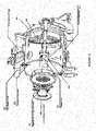
- FIGS 2 and 3 depict a schematic of the present FRC system 10.
- the FRC system 10 includes a central confinement vessel 100 surrounded by two diametrically opposed reversed-field-theta-pinch formation sections 200 and, beyond the formation sections 200, two divertor chambers 300 to control neutral density and impurity contamination.
- the present FRC system 10 was built to accommodate ultrahigh vacuum and operates at typical base pressures of 10 -8 torr. Such vacuum pressures require the use of double-pumped mating flanges between mating components, metal O-rings, high purity interior walls, as well as careful initial surface conditioning of all parts prior to assembly, such as physical and chemical cleaning followed by a 24 hour 250 °C vacuum baking and Hydrogen glow discharge cleaning.
- the reversed-field-theta-pinch formation sections 200 are standard field-reversed-theta-pinches (FRTPs), albeit with an advanced pulsed power formation system discussed in detail below (see Figures 4 through 6 ).
- Each formation section 200 is made of standard opaque industrial grade quartz tubes that feature a 2 millimeter inner lining of ultrapure quartz.
- the confinement chamber 100 is made of stainless steel to allow a multitude of radial and tangential ports; it also serves as a flux conserver on the timescale of the experiments described below and limits fast magnetic transients. Vacuums are created and maintained within the FRC system 10 with a set of dry scroll roughing pumps, turbo molecular pumps and cryo pumps.
- the magnetic system 400 is illustrated in Figures 2 and 3 .
- Figure 2 illustrates an FRC magnetic flux and density contours (as functions of the radial and axial coordinates) pertaining to an FRC 450 producible by the FRC system 10. These contours were obtained by a 2-D resistive Hall-MHD numerical simulation using code developed to simulate systems and methods corresponding to the FRC system 10, and agree well with measured experimental data.
- the FRC 450 consists of a torus of closed field lines at the interior 453 of the FRC 450 inside a separatrix 451, and of an annular edge layer 456 on the open field lines 452 just outside the separatrix 451.
- the edge layer 456 coalesces into jets 454 beyond the FRC length, providing a natural divertor.
- the main magnetic system 410 includes a series of quasi-dc coils 412, 414, and 416 that are situated at particular axial positions along the components, i.e., along the confinement chamber 100, the formation sections 200 and the divertors 300, of the FRC system 10.
- the quasi-dc coils 412, 414 and 416 are fed by quasi-dc switching power supplies and produce basic magnetic bias fields of about 0.1 T in the confinement chamber 100, the formation sections 200 and the divertors 300.
- the main magnetic system 410 includes quasi-dc mirror coils 420 (fed by switching supplies) between either end of the confinement chamber 100 and the adjacent formation sections 200.
- the quasi-dc mirror coils 420 provide magnetic mirror ratios of up to 5 and can be independently energized for equilibrium shaping control.
- mirror plugs 440 are positioned between each of the formation sections 200 and divertors 300.
- the mirror plugs 440 comprise compact quasi-dc mirror coils 430 and mirror plug coils 444.
- the quasi-dc mirror coils 430 include three coils 432, 434 and 436 (fed by switching supplies) that produce additional guide fields to focus the magnetic flux surfaces 455 towards the small diameter passage 442 passing through the mirror plug coils 444.
- the mirror plug coils 444 which wrap around the small diameter passage 442 and are fed by LC pulsed power circuitry, produce strong magnetic mirror fields of up to 4 T.
- this entire coil arrangement is to tightly bundle and guide the magnetic flux surfaces 455 and end-streaming plasma jets 454 into the remote chambers 310 of the divertors 300.
- a set of saddle-coil "antennas" 460 are located outside the confinement chamber 100, two on each side of the mid-plane, and are fed by dc power supplies.
- the saddle-coil antennas 460 can be configured to provide a quasi-static magnetic dipole or quadrupole field of about 0.01 T for controlling rotational instabilities and/or electron current control.
- the saddle-coil antennas 460 can flexibly provide magnetic fields that are either symmetric or antisymmetric about the machine's midplane, depending on the direction of the applied currents.
- the pulsed power formation systems 210 operate on a modified theta-pinch principle. There are two systems that each power one of the formation sections 200. Figures 4 through 6 illustrate the main building blocks and arrangement of the formation systems 210.
- Each skid 220 is composed of capacitors 221, inductors 223, fast high current switches 225 and associated trigger 222 and dump circuitry 224.
- each formation system 210 stores between 350-400 kJ of capacitive energy, which provides up to 35 GW of power to form and accelerate the FRCs. Coordinated operation of these components is achieved via a state-of-the-art trigger and control system 222 and 224 that allows synchronized timing between the formation systems 210 on each formation section 200 and minimizes switching jitter to tens of nanoseconds.
- Neutral atom beams 600 are deployed on the FRC system 10 to provide heating and current drive as well as to develop fast particle pressure.
- the individual beam lines comprising neutral atom beam injector systems 610 and 640 are located around the central confinement chamber 100 and inject fast particles tangentially to the FRC plasma (and perpendicular or at an angel normal to the major axis of symmetry in the central confinement vessel 100) with an impact parameter such that the target trapping zone lies well within the separatrix 451 (see Figure 2 ).
- Each injector system 610 and 640 is capable of injecting up to 1 MW of neutral beam power into the FRC plasma with particle energies between 20 and 40 keV.
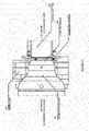
- the systems 610 and 640 are based on positive ion multi-aperture extraction sources and utilize geometric focusing, inertial cooling of the ion extraction grids and differential pumping. Apart from using different plasma sources, the systems 610 and 640 are primarily differentiated by their physical design to meet their respective mounting locations, yielding side and top injection capabilities. Typical components of these neutral beam injectors are specifically illustrated in Figure 7 for the side injector systems 610. As shown in Figure 7 , each individual neutral beam system 610 includes an RF plasma source 612 at an input end (this is substituted with an arc source in systems 640) with a magnetic screen 614 covering the end.
- An ion optical source and acceleration grids 616 is coupled to the plasma source 612 and a gate valve 620 is positioned between the ion optical source and acceleration grids 616 and a neutralizer 622.
- a deflection magnet 624 and an ion dump 628 are located between the neutralizer 622 and an aiming device 630 at the exit end.
- a cooling system comprises two cryo-refrigerators 634, two cryopanels 636 and a LN2 shroud 638. This flexible design allows for operation over a broad range of FRC parameters.
- An alternative configuration for the neutral atom beam injectors 600 is that of injecting the fast particles tangentially to the FRC plasma, but with an angle A less than 90° relative to the major axis of symmetry in the central confinement vessel 100.
- These types of orientation of the beam injectors 615 are shown in Figure 3C .
- the beam injectors 615 may be oriented such that the beam injectors 615 on either side of the mid-plane of the central confinement vessel 100 inject their particles towards the mid-plane.
- the axial position of these beam systems 600 may be chosen closer to the mid-plane.
- this arrangement of the beam injectors 615 allows more direct and independent control of the axial elongation and other characteristics of the FRC 450. For instance, injecting the beams at a shallow angle A relative to the vessel's major axis of symmetry will create an FRC plasma with longer axial extension and lower temperature while picking a more perpendicular angle A will lead to an axially shorter but hotter plasma. In this fashion the injection angle A and location of the beam injectors 615 can be optimized for different purposes.
- such angling and positioning of the beam injectors 615 can allow beams of higher energy (which is generally more favorable for depositing more power with less beam divergence) to be injected into lower magnetic fields than would otherwise be necessary to trap such beams. This is due to the fact that it is the azimuthal component of the energy that determines fast ion orbit scale (which becomes progressively smaller as the injection angle relative to the vessel's major axis of symmetry is reduced at constant beam energy). Furthermore, angled injection towards the mid-plane and with axial beam positions close to the mid-plane improves beam-plasma coupling, even as the FRC plasma shrinks or otherwise axially contracts during the injection period.
- a 12-barrel pellet injector 700 (see e.g. I. Vinyar et al., "Pellet Injectors Developed at PELIN for JET, TAE, and HL-2A," Proceedings of the 26th Fusion Science and Technology Symposium, 09/27 to 10/01 (2010 )) is utilized on FRC system 10.
- Figure 3 illustrates the layout of the pellet injector 700 on the FRC system 10.
- the cylindrical pellets (D ⁇ 1 mm, L ⁇ 1 - 2 mm) are injected into the FRC with a velocity in the range of 150 - 250 km/s.
- Each individual pellet contains about 5 ⁇ 10 19 hydrogen atoms, which is comparable to the FRC particle inventory.
- the FRC system 10 employs Titanium and Lithium deposition systems 810 and 820 that coat the plasma facing surfaces of the confinement chamber (or vessel) 100 and diverters 300 with films (tens of micrometers thick) of Ti and/or Li.
- the coatings are achieved via vapor deposition techniques.
- Solid Li and/or Ti are evaporated and/or sublimated and sprayed onto nearby surfaces to form the coatings.
- the sources are atomic ovens with guide nozzles (in case of Li) 822 or heated spheres of solid with guide shrouding (in case of Ti) 812.
- Li evaporator systems typically operate in a continuous mode while Ti sublimators are mostly operated intermittently in between plasma operation. Operating temperatures of these systems are above 600 °C to obtain fast deposition rates. To achieve good wall coverage, multiple strategically located evaporator/sublimator systems are necessary.
- Figure 9 details an arrangement of the gettering deposition systems 810 and 820 in the FRC system 10.
- the coatings act as gettering surfaces and effectively pump atomic and molecular hydrogenic species (H and D).
- the coatings also reduce other typical impurities such as Carbon and Oxygen to insignificant levels.
- the FRC system 10 employs sets of mirror coils 420, 430, and 444 as shown in Figures 2 and 3 .
- a first set of mirror coils 420 is located at the two axial ends of the confinement chamber 100 and is independently energized from the confinement coils 412, 414 and 416 of the main magnetic system 410.
- the first set of mirror coils 420 primarily helps to steer and axially contain the FRC 450 during merging and provides equilibrium shaping control during sustainment.
- the first mirror coil set 420 produces nominally higher magnetic fields (around 0.4 to 0.5 T) than the central confinement field produced by the central confinement coils 412.
- the second set of mirror coils 430 which includes three compact quasi-dc mirror coils 432, 434 and 436, is located between the formation sections 200 and the divertors 300 and are driven by a common switching power supply.
- the mirror coils 432, 434 and 436, together with the more compact pulsed mirror plug coils 444 (fed by a capacitive power supply) and the physical constriction 442 form the mirror plugs 440 that provide a narrow low gas conductance path with very high magnetic fields (between 2 to 4 T with risetimes of about 10 to 20 ms).
- the most compact pulsed mirror coils 444 are of compact radial dimensions, bore of 20 cm and similar length, compared to the meter-plus-scale bore and pancake design of the confinement coils 412, 414 and 416.
- the purpose of the mirror plugs 440 is multifold: (1) The coils 432, 434, 436 and 444 tightly bundle and guide the magnetic flux surfaces 452 and end-streaming plasma jets 454 into the remote divertor chambers 300. This assures that the exhaust particles reach the divertors 300 appropriately and that there are continuous flux surfaces 455 that trace from the open field line 452 region of the central FRC 450 all the way to the divertors 300.
- the constrictions 442 prevent back-streaming of gas from the formation sections 200 to the divertors 300 thereby reducing the number of neutral particles that has to be introduced into the entire FRC system 10 when commencing the start up of an FRC.
- the strong axial mirrors produced by the coils 432, 434, 436 and 444 reduce axial particle losses and thereby reduce the parallel particle diffusivity on open field lines.
- Plasma streams from guns 350 mounted in the divertor chambers 310 of the divertors 300 are intended to improve stability and neutral beam performance.
- the guns 350 are mounted on axis inside the chamber 310 of the divertors 300 as illustrated in Figures 3 and 10 and produce plasma flowing along the open flux lines 452 in the divertor 300 and towards the center of the confinement chamber 100.
- the guns 350 operate at a high density gas discharge in a washer-stack channel and are designed to generate several kiloamperes of fully ionized plasma for 5 to 10 ms.
- the guns 350 include a pulsed magnetic coil that matches the output plasma stream with the desired size of the plasma in the confinement chamber 100.
- the technical parameters of the guns 350 are characterized by a channel having a 5 to 13 cm outer diameter and up to about 10 cm inner diameter and provide a discharge current of 10-15 kA at 400-600 V with a gun-internal magnetic field of between 0.5 to 2.3 T.
- the gun plasma streams can penetrate the magnetic fields of the mirror plugs 440 and flow into the formation section 200 and confinement chamber 100.
- the efficiency of plasma transfer through the mirror plug 440 increases with decreasing distance between the gun 350 and the plug 440 and by making the plug 440 wider and shorter.
- the guns 350 can each deliver approximately 10 22 protons/s through the 2 to 4 T mirror plugs 440 with high ion and electron temperatures of about 150 to 300 eV and about 40 to 50 eV, respectively.
- the guns 350 provide significant refueling of the FRC edge layer 456, and an improved overall FRC particle confinement.
- a gas box could be utilized to puff additional gas into the plasma stream from the guns 350. This technique allows a several-fold increase in the injected plasma density.
- a gas box installed on the divertor 300 side of the mirror plugs 440 improves the refueling of the FRC edge layer 456, formation of the FRC 450, and plasma line-tying.
- Electrical biasing of open flux surfaces can provide radial potentials that give rise to azimuthal E ⁇ B motion that provides a control mechanism, analogous to turning a knob, to control rotation of the open field line plasma as well as the actual FRC core 450 via velocity shear.
- the FRC system 10 employs various electrodes strategically placed in various parts of the machine.
- Figure 3 depicts biasing electrodes positioned at locations within the FRC system 10.
- elctrodes there are 4 classes of elctrodes: (1) point electrodes 905 in the confinement chamber 100 that make contact with particular open field lines 452 in the edge of the FRC 450 to provide local charging, (2) annular electrodes 900 between the confinement chamber 100 and the formation sections 200 to charge far-edge flux layers 456 in an azimuthally symmetric fashion, (3) stacks of concentric electrodes 910 in the divertors 300 to charge multiple concentric flux layers 455 (whereby the selection of layers is controllable by adjusting coils 416 to adjust the divertor magnetic field so as to terminate the desired flux layers 456 on the appropriate electrodes 910), and finally (4) the anodes 920 (see
- Figure 10 of the plasma guns 350 themselves (which intercept inner open flux surfaces 455 near the separatrix of the FRC 450).
- Figures 10 and 11 show some typical designs for some of these.
- these electrodes are driven by pulsed or dc power sources at voltages up to about 800 V. Depending on electrode size and what flux surfaces are intersected, currents can be drawn in the kilo-ampere range.
- the standard plasma formation on the FRC system 10 follows the well-developed reversed-field-theta-pinch technique.
- a typical process for starting up an FRC commences by driving the quasi-dc coils 412, 414, 416, 420, 432, 434 and 436 to steady state operation.
- the RFTP pulsed power circuits of the pulsed power formation systems 210 then drive the pulsed fast reversed magnet field coils 232 to create a temporary reversed bias of about -0.05 T in the formation sections 200.
- a predetermined amount of neutral gas at 9-20 psi is injected into the two formation volumes defined by the quartz-tube chambers 240 of the (north and south) formation sections 200 via a set of azimuthally-oriented puff-vales at flanges located on the outer ends of the formation sections 200.
- a small RF ( ⁇ hundreds of kilo-hertz) field is generated from a set of antennas on the surface of the quartz tubes 240 to create pre-ionization in the form of local seed ionization regions within the neutral gas columns.
- This is followed by applying a theta-ringing modulation on the current driving the pulsed fast reversed magnet field coils 232, which leads to more global pre-ionization of the gas columns.
- the main pulsed power banks of the pulsed power formation systems 210 are fired to drive pulsed fast reversed magnet field coils 232 to create a forward-biased field of up to 0.4 T.
- This step can be time-sequenced such that the forward-biased field is generated uniformly throughout the length of the formation tubes 240 (static formation) or such that a consecutive peristaltic field modulation is achieved along the axis of the formation tubes 240 (dynamic formation).
- the multi-gigawatt pulsed power delivered to the forming plasma readily produces hot FRCs which are then ejected from the formation sections 200 via application of either a time-sequenced modulation of the forward magnetic field (magnetic peristalsis) or temporarily increased currents in the last coils of coil sets 232 near the axial outer ends of the formation tubes 210 (forming an axial magnetic field gradient that points axially towards the confinement chamber 100).
- the two (north and south) formation FRCs so formed and accelerated then expand into the larger diameter confinement chamber 100, where the quasi-dc coils 412 produce a forward-biased field to control radial expansion and provide the equilibrium external magnetic flux.
- the FRCs collide. During the collision the axial kinetic energies of the north and south formation FRCs are largely thermalized as the FRCs merge ultimately into a single FRC 450.
- a large set of plasma diagnostics are available in the confinement chamber 100 to study the equilibria of the FRC 450.
- Typical operating conditions in the FRC system 10 produce compound FRCs with separatrix radii of about 0.4 m and about 3 m axial extend. Further characteristics are external magnetic fields of about 0.1 T, plasma densities around 5 ⁇ 10 19 m -3 and total plasma temperature of up to 1 keV. Without any sustainment, i.e., no heating and/or current drive via neutral beam injection or other auxiliary means, the lifetime of these FRCs is limited to about 1 ms, the indigenous characteristic configuration decay time.
- Figure 12 shows a typical time evolution of the excluded flux radius, r ⁇ , which approximates the separatrix radius, r s , to illustrate the dynamics of the theta-pinch merging process of the FRC 450.
- the plasmoids compress axially, followed by a rapid radial and axial expansion, before eventually merging to form an FRC 450.
- Both radial and axial dynamics of the merging FRC 450 are evidenced by detailed density profile measurements and bolometer-based tomography.
- Total plasma temperature is shown in Figure 13(d) , derived from pressure balance and fully consistent with Thomson scattering and spectroscopy measurements.
- the FRC length shrinks steadily from 3 down to about 1 m during the FRC lifetime. This shrinkage, visible in Figure 14 , suggests that mostly convective energy loss dominates the FRC confinement.
- the magnetic field line tension in the end regions compresses the FRC axially, restoring axial and radial equilibrium.
- the FRC magnetic flux, particle inventory, and thermal energy decrease by roughly an order of magnitude in the first millisecond, when the FRC equilibrium appears to subside.
- fast (H) neutrals are injected perpendicular to B z in beams from the eight neutral beam injectors 600.
- the beams of fast neutrals are injected from the moment the north and south formation FRCs merge in the confinement chamber 100 into one FRC 450.
- the fast ions created primarily by charge exchange, have betatron orbits (with primary radii on the scale of the FRC topology or at least much larger than the characteristic magnetic field gradient length scale) that add to the azimuthal current of the FRC 450. After some fraction of the discharge (after 0.5 to 0.8 ms into the shot), a sufficiently large fast ion population significantly improves the inner FRC's stability and confinement properties (see e.g. M.W. Binderbauer and N. Rostoker, Plasma Phys. 56, part 3, 451 (1996 )). Furthermore, from a sustainment perspective, the beams from the neutral beam injectors 600 are also the primary means to drive current and heat the FRC plasma.
- the fast ions slow down primarily on plasma electrons.
- typical orbit-averaged slowing-down times of fast ions are 0.3 - 0.5 ms, which results in significant FRC heating, primarily of electrons.
- the fast ions make large radial excursions outside of the separatrix because the internal FRC magnetic field is inherently low (about 0.03 T on average for a 0.1 T external axial field).
- the fast ions would be vulnerable to charge exchange loss, if the neutral gas density were too high outside of the separatrix. Therefore, wall gettering and other techniques (such as the plasma gun 350 and mirror plugs 440 that contribute, amongst other things, to gas control) deployed on the FRC system 10 tend to minimize edge neutrals and enable the required build-up of fast ion current.
- frozen H or D pellets are injected into the FRC 450 from the pellet injector 700 to sustain the FRC particle inventory of the FRC 450.
- the anticipated ablation timescales are sufficiently short to provide a significant FRC particle source.
- This rate can also be increased by enlarging the surface area of the injected piece by breaking the individual pellet into smaller fragments while in the barrels or injection tubes of the pellet injector 700 and before entering the confinement chamber 100, a step that can be achieved by increasing the friction between the pellet and the walls of the injection tube by tightening the bend radius of the last segment of the injection tube right before entry into the confinement chamber 100.
- the pellet injection system 700 By virtue of varying the firing sequence and rate of the 12 barrels (injection tubes) as well as the fragmentation, it is possible to tune the pellet injection system 700 to provide just the desired level of particle inventory sustainment. In turn, this helps maintain the internal kinetic pressure in the FRC 450 and sustained operation and lifetime of the FRC 450.
- the pellet injectors 700 together with the neutral beam injectors 600 form the system that maintains a steady state and sustains the FRC 450.
- the pellet injector is not part of the invention.
- a compact toroid (CT) injector is provided, mainly for fueling field-reversed configuration (FRCs) plasmas.
- the CT injector 720 comprises a magnetized coaxial plasma-gun (MCPG), which, as shown in Figure 21 , includes coaxial cylindrical inner and outer electrodes 722 and 724, a bias coil positioned internal to the inner electrode 726 and an electrical break 728 on an end opposite the discharge of the CT injector 720.
- Gas is injected through a gas injection port 730 into a space between the inner and outer electrodes 722 and 724 and a Spheromak-like plasma is generated therefrom by discharge and pushed out from the gun by Lorentz force.
- a pair of CT injectors 720 are coupled to the confinement vessel 100 near and on opposition sides of the mid-plane of the vessel 100 to inject CTs into the central FRC plasma within the confinement vessel 100.
- the discharge end of the CT injectors 720 are directed towards the mid-plane of the confinement vessel 100 at an angel to the longitudinal axis of the confinement vessel 100 similar to the neutral beam injectors 615.
- the CT injector 720 include a drift tube 740 comprising an elongate cylindrical tube coupled to the discharge end of the CT injector 720.
- the drift tube 740 includes drift tube coils 742 positioned about and axially spaced along the tube.
- a plurality of diagnostic ports 744 are depicted along the length of the tube.
- the advantages of the CT injector 720 are: (1) control and adjustability of particle inventory per injected CT; (2) warm plasma is deposited (instead of cryogenic pellets); (3) system can be operated in rep-rate mode so as to allow for continuous fueling; (4) the system can also restore some magnetic flux as the injected CTs carry embedded magnetic field.
- the inner diameter of an outer electrode is 83.1 mm and the outer diameter of an inner electrode is 54.0 mm.
- the surface of the inner electrode 722 is preferably coated with tungsten in order to reduce impurities coming out from the electrode 722.
- the bias coil 726 is mounted inside of the inner electrode 722.
- the FRC system 10 utilizes an innovative technique to provide electron breaking via an externally applied static magnetic dipole or quadrupole field. This is accomplished via the external saddle coils 460 depicted in Figure 15 .
- the transverse applied radial magnetic field from the saddle coils 460 induces an axial electric field in the rotating FRC plasma.
- the required applied magnetic dipole (or quadrupole) field inside the plasma needs to be only of order 0.001 T to provide adequate electron breaking.
- the corresponding external field of about .015 T is small enough to not cause appreciable fast particle losses or otherwise negatively impact confinement.
- the applied magnetic dipole (or quadrupole) field contributes to suppress instabilities.
- the saddle coils 460 provide an additional level of control with regards to current maintenance and stability.
- the design of the pulsed coils 444 within the mirror plugs 440 permits the local generation of high magnetic fields (2 to 4 T) with modest (about 100 kJ) capacitive energy.
- all field lines within the formation volume are passing through the constrictions 442 at the mirror plugs 440, as suggested by the magnetic field lines in Figure 2 and plasma wall contact does not occur.
- the mirror plugs 440 in tandem with the quasi-dc divertor magnets 416 can be adjusted so to guide the field lines onto the divertor electrodes 910, or flare the field lines in an end cusp configuration (not shown). The latter improves stability and suppresses parallel electron thermal conduction.
- the mirror plugs 440 by themselves also contribute to neutral gas control.
- the mirror plugs 440 permit a better utilization of the deuterium gas puffed in to the quartz tubes during FRC formation, as gas back-streaming into the divertors 300 is significantly reduced by the small gas conductance of the plugs (a meager 500 L/s). Most of the residual puffed gas inside the formation tubes 210 is quickly ionized.
- the high-density plasma flowing through the mirror plugs 440 provides efficient neutral ionization hence an effective gas barrier.
- most of the neutrals recycled in the divertors 300 from the FRC edge layer 456 do not return to the confinement chamber 100.
- the neutrals associated with the operation of the plasma guns 350 will be mostly confined to the divertors 300.
- the mirror plugs 440 tend to improve the FRC edge layer confinement.
- the edge layer particle confinement time ⁇ ⁇ increases by up to an order of magnitude. Improving ⁇ ⁇ readily increases the FRC particle confinement.
- Use of the plasma guns 350 provides for this preferred edge stability. In this sense, the mirror plugs 440 and plasma gun 350 form an effective edge control system.
- the plasma guns 350 improve the stability of the FRC exhaust jets 454 by line-tying.
- the gun plasmas from the plasma guns 350 are generated without azimuthal angular momentum, which proves useful in controlling FRC rotational instabilities.
- the guns 350 are an effective means to control FRC stability without the need for the older quadrupole stabilization technique.
- the plasma guns 350 make it possible to take advantage of the beneficial effects of fast particles or access the advanced hybrid kinetic FRC regime as outlined in this disclosure. Therefore, the plasma guns 350 enable the FRC system 10 to be operated with saddle coil currents just adequate for electron breaking but below the threshold that would cause FRC instability and/or lead to dramatic fast particle diffusion.
- the supplied gun plasma would be comparable to the edge layer particle loss rate ( ⁇ 10 22 /s).
- the lifetime of the gun-produced plasma in the FRC system 10 is in the millisecond range. Indeed, consider the gun plasma with density n e ⁇ 10 13 cm -3 and ion temperature of about 200 eV, confined between the end mirror plugs 440.
- the trap length L and mirror ratio R are about 15 m and 20, respectively.
- the ion mean free path due to Coulomb collisions is ⁇ ii ⁇ 6 ⁇ 10 3 cm and, since ⁇ ii lnR/R ⁇ L, the ions are confined in the gas-dynamic regime.
- the plasma confinement time in this regime is ⁇ gd ⁇ RL/2V s ⁇ 2 ms, where V s is the ion sound speed.
- the classical ion confinement time for these plasma parameters would be ⁇ c ⁇ 0.5 ⁇ ii (lnR + (lnR) 0.5 ) ⁇ 0.7 ms.
- the anomalous transverse diffusion may, in principle, shorten the plasma confinement time.
- the estimated transverse confinement time for the gun plasma is t ⁇ > ⁇ gd ⁇ 2 ms.
- the guns would provide significant refueling of the FRC edge layer 456, and an improved overall FRC particle confinement.
- the gun plasma streams can be turned on in about 150 to 200 microseconds, which permits use in FRC start-up, translation, and merging into the confinement chamber 100. If turned on around t ⁇ 0 (FRC main bank initiation), the gun plasmas help to sustain the present dynamically formed and merged FRC 450. The combined particle inventories from the formation FRCs and from the guns is adequate for neutral beam capture, plasma heating, and long sustainment. If turned on at t in the range -1 to 0 ms, the gun plasmas can fill the quartz tubes 210 with plasma or ionize the gas puffed into the quartz tubes, thus permitting FRC formation with reduced or even perhaps zero puffed gas. The latter may require sufficiently cold formation plasma to permit fast diffusion of the reversed bias magnetic field.
- the plasma streams could fill the about 1 to 3 m 3 field line volume of the formation and confinement regions of the formation sections 200 and confinement chamber 100 with a target plasma density of a few 10 13 cm -3 , sufficient to allow neutral beam build-up prior to FRC arrival.
- the formation FRCs could then be formed and translated into the resulting confinement vessel plasma. In this way the plasma guns 350 enable a wide variety of operating conditions and parameter regimes.
- Control of the radial electric field profile in the edge layer 456 is beneficial in various ways to FRC stability and confinement.
- innovative biasing components deployed in the FRC system 10 it is possible to apply a variety of deliberate distributions of electric potentials to a group of open flux surfaces throughout the machine from areas well outside the central confinement region in the confinement chamber 100.
- radial electric fields can be generated across the edge layer 456 just outside of the FRC 450.
- These radial electric fields then modify the azimuthal rotation of the edge layer 456 and effect its confinement via E ⁇ B velocity shear. Any differential rotation between the edge layer 456 and the FRC core 453 can then be transmitted to the inside of the FRC plasma by shear.
- edge layer 456 directly impacts the FRC core 453. Furthermore, since the free energy in the plasma rotation can also be responsible for instabilities, this technique provides a direct means to control the onset and growth of instabilities.
- appropriate edge biasing provides an effective control of open field line transport and rotation as well as FRC core rotation.
- the location and shape of the various provided electrodes 900, 905, 910 and 920 allows for control of different groups of flux surfaces 455 and at different and independent potentials. In this way a wide array of different electric field configurations and strengths can be realized, each with different characteristic impact on plasma performance.
- a key advantage of all these innovative biasing techniques is the fact that core and edge plasma behavior can be effected from well outside the FRC plasma, i.e. there is no need to bring any physical components in touch with the central hot plasma (which would have severe implications for energy, flux and particle losses). This has a major beneficial impact on performance and all potential applications of the HPF concept.
- FIG. 16 illustrates this fact. Depicted is a set of curves showing how the FRC lifetime correlates with the length of the beam pulses. All other operating conditions are held constant for all discharges comprising this study. The data is averaged over many shots and, therefore, represents typical behavior. It is clearly evident that longer beam duration produces longer lived FRCs. Looking at this evidence as well as other diagnostics during this study, it demonstrates that beams increase stability and reduce losses.
- the correlation between beam pulse length and FRC lifetime is not perfect as beam trapping becomes inefficient below a certain plasma size, i.e., as the FRC 450 shrinks in physical size not all of the injected beams are intercepted and trapped.
- Shrinkage of the FRC is primarily due to the fact that net energy loss ( ⁇ 4 MW about midway through the discharge) from the FRC plasma during the discharge is somewhat larger than the total power fed into the FRC via the neutral beams ( ⁇ 2.5 MW) for the particular experimental setup. Locating the beams at a location closer to the mid-plane of the vessel 100 would tend to reduce these losses and extend FRC lifetime.
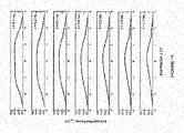
- Figure 17 illustrates the effects of different components to achieve the HPF regime. It shows a family of typical curves depicting the lifetime of the FRC 450 as a function of time. In all cases a constant, modest amount of beam power (about 2.5 MW) is injected for the full duration of each discharge. Each curve is representative of a different combination of components.
- operating the FRC system 10 without any mirror plugs 440, plasma guns 350 or gettering from the gettering systems 800 results in rapid onset of rotational instability and loss of the FRC topology. Adding only the mirror plugs 440 delays the onset of instabilities and increases confinement. Utilizing the combination of mirror plugs 440 and a plasma gun 350 further reduces instabilities and increases FRC lifetime.
- Figure 1 illustrates the change in particle confinement time in the FRC system 10 between the conventionally regime and the HPF regime. As can be seen, it has improved by well over a factor of 5 in the HPF regime.
- Figure 1 details the particle confinement time in the FRC system 10 relative to the particle confinement time in prior conventional FRC experiments. With regards to these other machines, the HPF regime of the FRC system 10 has improved confinement by a factor of between 5 and close to 20. Finally and most importantly, the nature of the confinement scaling of the FRC system 10 in the HPF regime is dramatically different from all prior measurements.
- Figure 18 shows data from a representative HPF regime discharge in the FRC system 10 as a function of time.
- Figure 18(a) depicts the excluded flux radius at the mid-plane.
- the conducting steel wall is no longer as good a flux conserver and the magnetic probes internal to the wall are augmented with probes outside the wall to properly account for magnetic flux diffusion through the steel.
- the HPF regime operating mode exhibits over 400% longer lifetime.
- FIG. 18(b) A representative cord of the line integrated density trace is shown in Figure 18(b) with its Abel inverted complement, the density contours, in Figure 18(c) .
- the plasma is more quiescent throughout the pulse, indicative of very stable operation.
- the peak density is also slightly lower in HPF shots - this is a consequence of the hotter total plasma temperature (up to a factor of 2) as shown in Figure 18(d) .
- the energy, particle and flux confinement times are 0.5 ms, 1 ms and 1 ms, respectively.
- the stored plasma energy is 2 kJ while the losses are about 4 MW, making this target very suitable for neutral beam sustainment.
- FIG 19 summarizes all advantages of the HPF regime in the form of a newly established experimental HPF flux confinement scaling.
- the flux confinement (and similarly, particle confinement and energy confinement) scales with roughly the square of the electron Temperature ( T e ) for a given separatrix radius (r s ).
- T e electron Temperature
- r s separatrix radius
- this scaling is a direct consequence of the HPF state and the large orbit (i.e. orbits on the scale of the FRC topology and/or at least the characteristic magnetic field gradient length scale) ion population. Fundamentally, this new scaling substantially favors high operating temperatures and enables relatively modest sized reactors.
- Figure 20 shows data in plot A from a representative HPF regime discharge in the FRC system 10 as a function of time and in plot B for a projected representative HPF regime discharge in the FRC system 10 as a function of time where the FRC 450 is sustained without decay through the duration of the neutral beam pulse.
- neutral beams with total power in the range of about 2.5-2.9 MW were injected into the FRC 450 for an active beam pulse length of about 6 ms.
- the plasma diamagnetic lifetime depicted in plot A was about 5.2 ms. More recent data shows a plasma diamagnetic lifetime of about 7.2 ms is achievable with an active beam pulse length of about 7 ms.
- the correlation between beam pulse length and FRC lifetime is not perfect as beam trapping becomes inefficient below a certain plasma size, i.e., as the FRC 450 shrinks in physical size not all of the injected beams are intercepted and trapped.
- Shrinkage or decay of the FRC is primarily due to the fact that net energy loss (-4 MW about midway through the discharge) from the FRC plasma during the discharge is somewhat larger than the total power fed into the FRC via the neutral beams (-2.5 MW) for the particular experimental setup.
- angled beam injection from the neutral beam guns 600 towards the mid-plane improves beam-plasma coupling, even as the FRC plasma shrinks or otherwise axially contracts during the injection period.
- appropriate pellet fueling will maintain the requisite plasma density.
- Plot B is the result of simulations run using an active beam pulse length of about 6 ms and total beam power from the neutral beam guns 600 of slightly more than about 10 MW, where neutral beams shall inject H (or D) neutrals with particle energy of about 15 keV.
- the equivalent current injected by each of the beams is about 110 A.
- the beam injection angle to the device axis was about 20°, target radius 0.19 m. Injection angle can be changed within the range 15° - 25°.
- the beams are to be injected in the co-current direction azimuthally.
- the net side force as well as net axial force from the neutral beam momentum injection shall be minimized.
- fast (H) neutrals are injected from the neutral beam injectors 600 from the moment the north and south formation FRCs merge in the confinement chamber 100 into one FRC 450.
- the steady state diamagnetic lifetime of the FRC 450 will be the length of the beam pulse.
- the key correlation plot B shows is that when the beams are turned off the plasma or FRC begins to decay at that time, but not before. The decay will be similar to that which is observed in discharges which are not beam-assisted - probably on order of 1 ms beyond the beam turn off time - and is simply a reflection of the characteristic decay time of the plasma driven by the intrinsic loss processes.
Landscapes
- Physics & Mathematics (AREA)
- Engineering & Computer Science (AREA)
- Plasma & Fusion (AREA)
- Spectroscopy & Molecular Physics (AREA)
- Optics & Photonics (AREA)
- High Energy & Nuclear Physics (AREA)
- General Engineering & Computer Science (AREA)
- Plasma Technology (AREA)
- Reinforced Plastic Materials (AREA)
- Moulding By Coating Moulds (AREA)
- Prostheses (AREA)
- Shaping Of Tube Ends By Bending Or Straightening (AREA)
- Pens And Brushes (AREA)
Priority Applications (4)
| Application Number | Priority Date | Filing Date | Title |
|---|---|---|---|
| RS20220978A RS63672B1 (sr) | 2014-10-30 | 2015-10-30 | Sistemi za formiranje i održavanje frc visokih performansi |
| SI201531897T SI3589083T1 (sl) | 2014-10-30 | 2015-10-30 | Sistem za ustvarjanje in vzdrževanje visoko zmogljivega FRC |
| HRP20221278TT HRP20221278T1 (hr) | 2014-10-30 | 2015-10-30 | Sustavi za formiranje i održavanje frc visokih performansi |
| SM20220420T SMT202200420T1 (it) | 2014-10-30 | 2015-10-30 | Sistemi per la formazione e il mantenimento di frc a rendimento alto |
Applications Claiming Priority (3)
| Application Number | Priority Date | Filing Date | Title |
|---|---|---|---|
| US201462072611P | 2014-10-30 | 2014-10-30 | |
| PCT/US2015/058473 WO2016070126A1 (en) | 2014-10-30 | 2015-10-30 | Systems and methods for forming and maintaining a high performance frc |
| EP15854636.6A EP3213608B1 (en) | 2014-10-30 | 2015-10-30 | Systems and methods for forming and maintaining a plasma in a high performance frc |
Related Parent Applications (1)
| Application Number | Title | Priority Date | Filing Date |
|---|---|---|---|
| EP15854636.6A Division EP3213608B1 (en) | 2014-10-30 | 2015-10-30 | Systems and methods for forming and maintaining a plasma in a high performance frc |
Publications (2)
| Publication Number | Publication Date |
|---|---|
| EP3589083A1 EP3589083A1 (en) | 2020-01-01 |
| EP3589083B1 true EP3589083B1 (en) | 2022-08-24 |
Family
ID=55858430
Family Applications (2)
| Application Number | Title | Priority Date | Filing Date |
|---|---|---|---|
| EP19187386.8A Active EP3589083B1 (en) | 2014-10-30 | 2015-10-30 | Systems for forming and maintaining a high performance frc |
| EP15854636.6A Active EP3213608B1 (en) | 2014-10-30 | 2015-10-30 | Systems and methods for forming and maintaining a plasma in a high performance frc |
Family Applications After (1)
| Application Number | Title | Priority Date | Filing Date |
|---|---|---|---|
| EP15854636.6A Active EP3213608B1 (en) | 2014-10-30 | 2015-10-30 | Systems and methods for forming and maintaining a plasma in a high performance frc |
Country Status (34)
| Country | Link |
|---|---|
| US (3) | US10440806B2 (pl) |
| EP (2) | EP3589083B1 (pl) |
| JP (2) | JP6855374B2 (pl) |
| KR (1) | KR102590200B1 (pl) |
| CN (2) | CN107006110B (pl) |
| AR (1) | AR102474A1 (pl) |
| AU (2) | AU2015338965B2 (pl) |
| BR (1) | BR112017008768B1 (pl) |
| CA (1) | CA2965682C (pl) |
| CL (1) | CL2017001075A1 (pl) |
| CY (1) | CY1122049T1 (pl) |
| DK (2) | DK3589083T3 (pl) |
| EA (2) | EA038824B1 (pl) |
| ES (2) | ES2746302T3 (pl) |
| HR (2) | HRP20191773T1 (pl) |
| HU (2) | HUE060221T2 (pl) |
| IL (1) | IL251583B2 (pl) |
| LT (2) | LT3213608T (pl) |
| MX (2) | MX369532B (pl) |
| MY (1) | MY181502A (pl) |
| NZ (2) | NZ730979A (pl) |
| PE (1) | PE20170743A1 (pl) |
| PH (2) | PH12017500726A1 (pl) |
| PL (2) | PL3589083T3 (pl) |
| PT (2) | PT3589083T (pl) |
| RS (2) | RS63672B1 (pl) |
| SA (1) | SA517381392B1 (pl) |
| SG (2) | SG11201703167UA (pl) |
| SI (2) | SI3213608T1 (pl) |
| SM (2) | SMT202200420T1 (pl) |
| TW (2) | TWI678950B (pl) |
| UA (1) | UA126267C2 (pl) |
| WO (1) | WO2016070126A1 (pl) |
| ZA (1) | ZA201702384B (pl) |
Families Citing this family (47)
| Publication number | Priority date | Publication date | Assignee | Title |
|---|---|---|---|---|
| US11000705B2 (en) * | 2010-04-16 | 2021-05-11 | W. Davis Lee | Relativistic energy compensating cancer therapy apparatus and method of use thereof |
| DK3223284T3 (da) | 2011-11-14 | 2019-05-20 | Univ California | Fremgangsmåde til dannelse og opretholdelse af højydelses-frc |
| EP3312843B1 (en) * | 2013-09-24 | 2019-10-23 | TAE Technologies, Inc. | Systems for forming and maintaining a high performance frc |
| US10892140B2 (en) | 2018-07-27 | 2021-01-12 | Eagle Harbor Technologies, Inc. | Nanosecond pulser bias compensation |
| US11539352B2 (en) | 2013-11-14 | 2022-12-27 | Eagle Harbor Technologies, Inc. | Transformer resonant converter |
| US10020800B2 (en) | 2013-11-14 | 2018-07-10 | Eagle Harbor Technologies, Inc. | High voltage nanosecond pulser with variable pulse width and pulse repetition frequency |
| US10978955B2 (en) | 2014-02-28 | 2021-04-13 | Eagle Harbor Technologies, Inc. | Nanosecond pulser bias compensation |
| CN106105033B (zh) | 2013-11-14 | 2019-04-12 | 鹰港科技有限公司 | 高压纳秒脉冲发生器 |
| US10483089B2 (en) | 2014-02-28 | 2019-11-19 | Eagle Harbor Technologies, Inc. | High voltage resistive output stage circuit |
| KR102519865B1 (ko) | 2014-10-13 | 2023-04-07 | 티에이이 테크놀로지스, 인크. | 콤팩트 토리를 합병 및 압축하는 시스템 및 방법 |
| CN107006110B (zh) * | 2014-10-30 | 2020-04-21 | 阿尔法能源技术公司 | 用于形成和保持高性能frc的系统和方法 |
| CA2983344A1 (en) | 2015-05-12 | 2016-11-17 | Tri Alpha Energy, Inc. | Systems and methods for reducing undesired eddy currents |
| WO2017083796A1 (en) | 2015-11-13 | 2017-05-18 | Tri Alpha Energy, Inc. | Systems and methods for frc plasma position stability |
| US11430635B2 (en) | 2018-07-27 | 2022-08-30 | Eagle Harbor Technologies, Inc. | Precise plasma control system |
| US11004660B2 (en) | 2018-11-30 | 2021-05-11 | Eagle Harbor Technologies, Inc. | Variable output impedance RF generator |
| CA3041826A1 (en) * | 2016-10-28 | 2018-05-03 | Tae Technologies, Inc. | Systems and methods for improved sustainment of a high performance frc elevated energies utilizing neutral beam injectors with tunable beam energies |
| SG11201903447WA (en) | 2016-11-04 | 2019-05-30 | Tae Technologies Inc | Systems and methods for improved sustainment of a high performance frc with multi-scaled capture type vacuum pumping |
| WO2018093941A1 (en) * | 2016-11-15 | 2018-05-24 | Tae Technologies, Inc. | Systems and methods for improved sustainment of a high performance frc and high harmonic fast wave electron heating in a high performance frc |
| WO2018096523A1 (en) * | 2016-11-28 | 2018-05-31 | Magna Mirrors Of America, Inc. | Exterior illumination and icon projection module for vehicle |
| CN110692188B (zh) | 2017-02-07 | 2022-09-09 | 鹰港科技有限公司 | 变压器谐振转换器 |
| EP3813259B1 (en) * | 2017-03-31 | 2022-10-26 | Eagle Harbor Technologies, Inc. | High voltage resistive output stage circuit |
| CN107278010A (zh) * | 2017-06-14 | 2017-10-20 | 中国科学院合肥物质科学研究院 | 一种在等离子体强磁场位置注入中性束的磁镜装置 |
| CN111264032B (zh) | 2017-08-25 | 2022-08-19 | 鹰港科技有限公司 | 使用纳秒脉冲的任意波形生成 |
| CN107797137B (zh) * | 2017-10-30 | 2023-11-28 | 中国工程物理研究院流体物理研究所 | 一种直线感应电子加速器试验平台及双线圈探测结构 |
| KR101886755B1 (ko) * | 2017-11-17 | 2018-08-09 | 한국원자력연구원 | 다중 펄스 플라즈마를 이용한 음이온 공급의 연속화 시스템 및 방법 |
| US11302518B2 (en) | 2018-07-27 | 2022-04-12 | Eagle Harbor Technologies, Inc. | Efficient energy recovery in a nanosecond pulser circuit |
| US11532457B2 (en) | 2018-07-27 | 2022-12-20 | Eagle Harbor Technologies, Inc. | Precise plasma control system |
| US11222767B2 (en) | 2018-07-27 | 2022-01-11 | Eagle Harbor Technologies, Inc. | Nanosecond pulser bias compensation |
| US11810761B2 (en) | 2018-07-27 | 2023-11-07 | Eagle Harbor Technologies, Inc. | Nanosecond pulser ADC system |
| EP4568091A3 (en) | 2018-08-10 | 2025-09-17 | Eagle Harbor Technologies, Inc. | Plasma sheath control for rf plasma reactors |
| US12456604B2 (en) | 2019-12-24 | 2025-10-28 | Eagle Harbor Technologies, Inc. | Nanosecond pulser RF isolation for plasma systems |
| TWI783203B (zh) | 2019-01-08 | 2022-11-11 | 美商鷹港科技股份有限公司 | 奈秒脈波產生器電路 |
| US11672074B2 (en) | 2019-07-11 | 2023-06-06 | Lockheed Martin Corporation | Shielding structures in plasma environment |
| TWI719616B (zh) * | 2019-09-02 | 2021-02-21 | 馬來西亞商愛億集團有限公司 | 鍍膜材料自動換料暨加熱汽化裝置及方法 |
| WO2021087342A1 (en) * | 2019-10-31 | 2021-05-06 | Friedlander Gregory | Method for dimensional manipulation |
| TWI778449B (zh) | 2019-11-15 | 2022-09-21 | 美商鷹港科技股份有限公司 | 高電壓脈衝電路 |
| KR102591378B1 (ko) | 2019-12-24 | 2023-10-19 | 이글 하버 테크놀로지스, 인코포레이티드 | 플라즈마 시스템을 위한 나노초 펄서 rf 절연 |
| KR20220127297A (ko) | 2020-01-13 | 2022-09-19 | 티에이이 테크놀로지스, 인크. | 스페로막 병합 및 중성 빔 주입을 통한 고에너지 및 온도 frc 플라즈마를 형성 및 유지를 위한 시스템 및 방법 |
| JP7486738B2 (ja) * | 2020-03-31 | 2024-05-20 | 日本電子株式会社 | 物理パッケージ、光格子時計用物理パッケージ、原子時計用物理パッケージ、原子干渉計用物理パッケージ、及び、量子情報処理デバイス用物理パッケージ |
| US11967484B2 (en) | 2020-07-09 | 2024-04-23 | Eagle Harbor Technologies, Inc. | Ion current droop compensation |
| KR102478843B1 (ko) * | 2020-11-03 | 2022-12-19 | 울산과학기술원 | 스파크 플라즈마 소결을 이용한 고밀도 핵연료 소결체 제조방법 |
| IL281747B2 (en) | 2021-03-22 | 2024-04-01 | N T Tao Ltd | High efficiency plasma creation system and method |
| US20230245792A1 (en) * | 2022-01-28 | 2023-08-03 | Fusion Energy Associates LLC | Increasing energy gain in magnetically confined plasmas by increasing the edge temperature: the super-xt divertor |
| CN114429827B (zh) * | 2022-04-07 | 2022-06-07 | 西南交通大学 | 一种仿星器线圈固定系统 |
| US11824542B1 (en) | 2022-06-29 | 2023-11-21 | Eagle Harbor Technologies, Inc. | Bipolar high voltage pulser |
| JP2025538072A (ja) | 2022-09-29 | 2025-11-26 | イーグル ハーバー テクノロジーズ,インク. | 高電圧プラズマ制御 |
| CN116153532B (zh) * | 2023-04-23 | 2023-07-25 | 中国科学院合肥物质科学研究院 | 一种满足千秒长脉冲等离子体放电的协同加料系统及方法 |
Family Cites Families (153)
| Publication number | Priority date | Publication date | Assignee | Title |
|---|---|---|---|---|
| US3120470A (en) | 1954-04-13 | 1964-02-04 | Donald H Imhoff | Method of producing neutrons |
| US3170841A (en) | 1954-07-14 | 1965-02-23 | Richard F Post | Pyrotron thermonuclear reactor and process |
| US3015618A (en) | 1958-06-30 | 1962-01-02 | Thomas H Stix | Apparatus for heating a plasma |
| US3071525A (en) | 1958-08-19 | 1963-01-01 | Nicholas C Christofilos | Method and apparatus for producing thermonuclear reactions |
| US3052617A (en) | 1959-06-23 | 1962-09-04 | Richard F Post | Stellarator injector |
| US3036963A (en) | 1960-01-25 | 1962-05-29 | Nicholas C Christofilos | Method and apparatus for injecting and trapping electrons in a magnetic field |
| BE591516A (pl) | 1960-02-26 | |||
| US3182213A (en) | 1961-06-01 | 1965-05-04 | Avco Corp | Magnetohydrodynamic generator |
| US3132996A (en) | 1962-12-10 | 1964-05-12 | William R Baker | Contra-rotating plasma system |
| US3386883A (en) | 1966-05-13 | 1968-06-04 | Itt | Method and apparatus for producing nuclear-fusion reactions |
| US3530036A (en) | 1967-12-15 | 1970-09-22 | Itt | Apparatus for generating fusion reactions |
| US3530497A (en) | 1968-04-24 | 1970-09-22 | Itt | Apparatus for generating fusion reactions |
| US3527977A (en) | 1968-06-03 | 1970-09-08 | Atomic Energy Commission | Moving electrons as an aid to initiating reactions in thermonuclear devices |
| US3577317A (en) | 1969-05-01 | 1971-05-04 | Atomic Energy Commission | Controlled fusion reactor |
| US3621310A (en) | 1969-05-30 | 1971-11-16 | Hitachi Ltd | Duct for magnetohydrodynamic thermal to electrical energy conversion apparatus |
| US3664921A (en) | 1969-10-16 | 1972-05-23 | Atomic Energy Commission | Proton e-layer astron for producing controlled fusion reactions |
| AT340010B (de) | 1970-05-21 | 1977-11-25 | Nowak Karl Ing | Einrichtung zur erzielung einer nuklearen reaktion mittels kunstlichem plasma vorzugsweise zur kontrollierten atomkernfusion |
| US3668065A (en) | 1970-09-15 | 1972-06-06 | Atomic Energy Commission | Apparatus for the conversion of high temperature plasma energy into electrical energy |
| US3663362A (en) | 1970-12-22 | 1972-05-16 | Atomic Energy Commission | Controlled fusion reactor |
| LU65432A1 (pl) | 1972-05-29 | 1972-08-24 | ||
| US4233537A (en) | 1972-09-18 | 1980-11-11 | Rudolf Limpaecher | Multicusp plasma containment apparatus |
| US4182650A (en) | 1973-05-17 | 1980-01-08 | Fischer Albert G | Pulsed nuclear fusion reactor |
| US5015432A (en) | 1973-10-24 | 1991-05-14 | Koloc Paul M | Method and apparatus for generating and utilizing a compound plasma configuration |
| US5041760A (en) | 1973-10-24 | 1991-08-20 | Koloc Paul M | Method and apparatus for generating and utilizing a compound plasma configuration |
| US4010396A (en) | 1973-11-26 | 1977-03-01 | Kreidl Chemico Physical K.G. | Direct acting plasma accelerator |
| FR2270733A1 (en) | 1974-02-08 | 1975-12-05 | Thomson Csf | Magnetic field vehicle detector unit - receiver detects changes produced in an emitted magnetic field |
| US4098643A (en) | 1974-07-09 | 1978-07-04 | The United States Of America As Represented By The United States Department Of Energy | Dual-function magnetic structure for toroidal plasma devices |
| US4057462A (en) | 1975-02-26 | 1977-11-08 | The United States Of America As Represented By The United States Energy Research And Development Administration | Radio frequency sustained ion energy |
| US4054846A (en) | 1975-04-02 | 1977-10-18 | Bell Telephone Laboratories, Incorporated | Transverse-excitation laser with preionization |
| US4065351A (en) | 1976-03-25 | 1977-12-27 | The United States Of America As Represented By The United States Energy Research And Development Administration | Particle beam injection system |
| US4166760A (en) * | 1977-10-04 | 1979-09-04 | The United States Of America As Represented By The United States Department Of Energy | Plasma confinement apparatus using solenoidal and mirror coils |
| US4347621A (en) | 1977-10-25 | 1982-08-31 | Environmental Institute Of Michigan | Trochoidal nuclear fusion reactor |
| US4303467A (en) | 1977-11-11 | 1981-12-01 | Branson International Plasma Corporation | Process and gas for treatment of semiconductor devices |
| US4274919A (en) | 1977-11-14 | 1981-06-23 | General Atomic Company | Systems for merging of toroidal plasmas |
| US4202725A (en) | 1978-03-08 | 1980-05-13 | Jarnagin William S | Converging beam fusion system |
| US4189346A (en) | 1978-03-16 | 1980-02-19 | Jarnagin William S | Operationally confined nuclear fusion system |
| US4246067A (en) | 1978-08-30 | 1981-01-20 | Linlor William I | Thermonuclear fusion system |
| US4267488A (en) | 1979-01-05 | 1981-05-12 | Trisops, Inc. | Containment of plasmas at thermonuclear temperatures |
| US4397810A (en) | 1979-03-16 | 1983-08-09 | Energy Profiles, Inc. | Compressed beam directed particle nuclear energy generator |
| US4314879A (en) | 1979-03-22 | 1982-02-09 | The United States Of America As Represented By The United States Department Of Energy | Production of field-reversed mirror plasma with a coaxial plasma gun |
| US4416845A (en) | 1979-08-02 | 1983-11-22 | Energy Profiles, Inc. | Control for orbiting charged particles |
| JPS5829568B2 (ja) | 1979-12-07 | 1983-06-23 | 岩崎通信機株式会社 | 2ビ−ム1電子銃陰極線管 |
| US4548782A (en) | 1980-03-27 | 1985-10-22 | The United States Of America As Represented By The Secretary Of The Navy | Tokamak plasma heating with intense, pulsed ion beams |
| US4390494A (en) | 1980-04-07 | 1983-06-28 | Energy Profiles, Inc. | Directed beam fusion reaction with ion spin alignment |
| US4350927A (en) | 1980-05-23 | 1982-09-21 | The United States Of America As Represented By The United States Department Of Energy | Means for the focusing and acceleration of parallel beams of charged particles |
| US4317057A (en) | 1980-06-16 | 1982-02-23 | Bazarov Georgy P | Channel of series-type magnetohydrodynamic generator |
| US4434130A (en) | 1980-11-03 | 1984-02-28 | Energy Profiles, Inc. | Electron space charge channeling for focusing ion beams |
| US4584160A (en) | 1981-09-30 | 1986-04-22 | Tokyo Shibaura Denki Kabushiki Kaisha | Plasma devices |
| US4543231A (en) | 1981-12-14 | 1985-09-24 | Ga Technologies Inc. | Multiple pinch method and apparatus for producing average magnetic well in plasma confinement |
| US4560528A (en) | 1982-04-12 | 1985-12-24 | Ga Technologies Inc. | Method and apparatus for producing average magnetic well in a reversed field pinch |
| JPH06105597B2 (ja) | 1982-08-30 | 1994-12-21 | 株式会社日立製作所 | マイクロ波プラズマ源 |
| JPS5960899A (ja) | 1982-09-29 | 1984-04-06 | 株式会社東芝 | イオン・エネルギ−回収装置 |
| US4618470A (en) | 1982-12-01 | 1986-10-21 | Austin N. Stanton | Magnetic confinement nuclear energy generator |
| US4483737A (en) | 1983-01-31 | 1984-11-20 | University Of Cincinnati | Method and apparatus for plasma etching a substrate |
| US4601871A (en) * | 1983-05-17 | 1986-07-22 | The United States Of America As Represented By The United States Department Of Energy | Steady state compact toroidal plasma production |
| US4650631A (en) | 1984-05-14 | 1987-03-17 | The University Of Iowa Research Foundation | Injection, containment and heating device for fusion plasmas |
| US4639348A (en) | 1984-11-13 | 1987-01-27 | Jarnagin William S | Recyclotron III, a recirculating plasma fusion system |
| US4615755A (en) | 1985-08-07 | 1986-10-07 | The Perkin-Elmer Corporation | Wafer cooling and temperature control for a plasma etching system |
| US4826646A (en) | 1985-10-29 | 1989-05-02 | Energy/Matter Conversion Corporation, Inc. | Method and apparatus for controlling charged particles |
| US4630939A (en) | 1985-11-15 | 1986-12-23 | The Dow Chemical Company | Temperature measuring apparatus |
| SE450060B (sv) | 1985-11-27 | 1987-06-01 | Rolf Lennart Stenbacka | Forfarande for att astadkomma fusionsreaktioner, samt anordning for fusionsreaktor |
| US4687616A (en) | 1986-01-15 | 1987-08-18 | The United States Of America As Represented By The United States Department Of Energy | Method and apparatus for preventing cyclotron breakdown in partially evacuated waveguide |
| US4894199A (en) | 1986-06-11 | 1990-01-16 | Norman Rostoker | Beam fusion device and method |
| DK556887D0 (da) | 1987-10-23 | 1987-10-23 | Risoe Forskningscenter | Fremgangsmaade til fremstilling af en pille og injektor til injektion af saadan pille |
| ATE137880T1 (de) | 1990-01-22 | 1996-05-15 | Steudtner Werner K Dipl Ing | Kernfusionsreaktor |
| US5160695A (en) | 1990-02-08 | 1992-11-03 | Qed, Inc. | Method and apparatus for creating and controlling nuclear fusion reactions |
| US5311028A (en) | 1990-08-29 | 1994-05-10 | Nissin Electric Co., Ltd. | System and method for producing oscillating magnetic fields in working gaps useful for irradiating a surface with atomic and molecular ions |
| US5122662A (en) | 1990-10-16 | 1992-06-16 | Schlumberger Technology Corporation | Circular induction accelerator for borehole logging |
| US5206516A (en) | 1991-04-29 | 1993-04-27 | International Business Machines Corporation | Low energy, steered ion beam deposition system having high current at low pressure |
| US6488807B1 (en) | 1991-06-27 | 2002-12-03 | Applied Materials, Inc. | Magnetic confinement in a plasma reactor having an RF bias electrode |
| US5207760A (en) | 1991-07-23 | 1993-05-04 | Trw Inc. | Multi-megawatt pulsed inductive thruster |
| US5323442A (en) | 1992-02-28 | 1994-06-21 | Ruxam, Inc. | Microwave X-ray source and methods of use |
| US5502354A (en) | 1992-07-31 | 1996-03-26 | Correa; Paulo N. | Direct current energized pulse generator utilizing autogenous cyclical pulsed abnormal glow discharges |
| RU2056649C1 (ru) | 1992-10-29 | 1996-03-20 | Сергей Николаевич Столбов | Способ управляемого термоядерного синтеза и управляемый термоядерный реактор для его осуществления |
| US5339336A (en) | 1993-02-17 | 1994-08-16 | Cornell Research Foundation, Inc. | High current ion ring accelerator |
| FR2705584B1 (fr) | 1993-05-26 | 1995-06-30 | Commissariat Energie Atomique | Dispositif de séparation isotopique par résonance cyclotronique ionique. |
| US5473165A (en) | 1993-11-16 | 1995-12-05 | Stinnett; Regan W. | Method and apparatus for altering material |
| DE69421157T2 (de) | 1993-12-21 | 2000-04-06 | Sumitomo Heavy Industries, Ltd. | Plasmastrahl-Erzeugungsverfahren und Vorrichtung die einen Hochleistungsplasmastrahl erzeugen Kann |
| US5537005A (en) | 1994-05-13 | 1996-07-16 | Hughes Aircraft | High-current, low-pressure plasma-cathode electron gun |
| US5420425A (en) | 1994-05-27 | 1995-05-30 | Finnigan Corporation | Ion trap mass spectrometer system and method |
| US5656519A (en) | 1995-02-14 | 1997-08-12 | Nec Corporation | Method for manufacturing salicide semiconductor device |
| US5653811A (en) | 1995-07-19 | 1997-08-05 | Chan; Chung | System for the plasma treatment of large area substrates |
| US20040213368A1 (en) | 1995-09-11 | 2004-10-28 | Norman Rostoker | Fusion reactor that produces net power from the p-b11 reaction |
| EP0876663B1 (en) | 1995-09-25 | 2003-11-12 | KOLOC, Paul M. | Apparatus for generating a plasma |
| JP3385327B2 (ja) | 1995-12-13 | 2003-03-10 | 株式会社日立製作所 | 三次元四重極質量分析装置 |
| US5764715A (en) | 1996-02-20 | 1998-06-09 | Sandia Corporation | Method and apparatus for transmutation of atomic nuclei |
| KR100275597B1 (ko) | 1996-02-23 | 2000-12-15 | 나카네 히사시 | 플리즈마처리장치 |
| US6000360A (en) | 1996-07-03 | 1999-12-14 | Tokyo Electron Limited | Plasma processing apparatus |
| US5811201A (en) | 1996-08-16 | 1998-09-22 | Southern California Edison Company | Power generation system utilizing turbine and fuel cell |
| US5923716A (en) | 1996-11-07 | 1999-07-13 | Meacham; G. B. Kirby | Plasma extrusion dynamo and methods related thereto |
| JP3582287B2 (ja) | 1997-03-26 | 2004-10-27 | 株式会社日立製作所 | エッチング装置 |
| JPH10335096A (ja) | 1997-06-03 | 1998-12-18 | Hitachi Ltd | プラズマ処理装置 |
| US6894446B2 (en) | 1997-10-17 | 2005-05-17 | The Regents Of The University Of California | Controlled fusion in a field reversed configuration and direct energy conversion |
| US6628740B2 (en) | 1997-10-17 | 2003-09-30 | The Regents Of The University Of California | Controlled fusion in a field reversed configuration and direct energy conversion |
| US6271529B1 (en) | 1997-12-01 | 2001-08-07 | Ebara Corporation | Ion implantation with charge neutralization |
| US6390019B1 (en) | 1998-06-11 | 2002-05-21 | Applied Materials, Inc. | Chamber having improved process monitoring window |
| FR2780499B1 (fr) | 1998-06-25 | 2000-08-18 | Schlumberger Services Petrol | Dispositifs de caracterisation de l'ecoulement d'un fluide polyphasique |
| US6335535B1 (en) | 1998-06-26 | 2002-01-01 | Nissin Electric Co., Ltd | Method for implanting negative hydrogen ion and implanting apparatus |
| US6255648B1 (en) | 1998-10-16 | 2001-07-03 | Applied Automation, Inc. | Programmed electron flux |
| US6248251B1 (en) | 1999-02-19 | 2001-06-19 | Tokyo Electron Limited | Apparatus and method for electrostatically shielding an inductively coupled RF plasma source and facilitating ignition of a plasma |
| US6572935B1 (en) * | 1999-03-13 | 2003-06-03 | The Regents Of The University Of California | Optically transparent, scratch-resistant, diamond-like carbon coatings |
| US6755086B2 (en) | 1999-06-17 | 2004-06-29 | Schlumberger Technology Corporation | Flow meter for multi-phase mixtures |
| US6322706B1 (en) | 1999-07-14 | 2001-11-27 | Archimedes Technology Group, Inc. | Radial plasma mass filter |
| US6452168B1 (en) | 1999-09-15 | 2002-09-17 | Ut-Battelle, Llc | Apparatus and methods for continuous beam fourier transform mass spectrometry |
| DE10060002B4 (de) | 1999-12-07 | 2016-01-28 | Komatsu Ltd. | Vorrichtung zur Oberflächenbehandlung |
| US6593539B1 (en) | 2000-02-25 | 2003-07-15 | George Miley | Apparatus and methods for controlling charged particles |
| US6408052B1 (en) | 2000-04-06 | 2002-06-18 | Mcgeoch Malcolm W. | Z-pinch plasma X-ray source using surface discharge preionization |
| US6593570B2 (en) | 2000-05-24 | 2003-07-15 | Agilent Technologies, Inc. | Ion optic components for mass spectrometers |
| US6664740B2 (en) | 2001-02-01 | 2003-12-16 | The Regents Of The University Of California | Formation of a field reversed configuration for magnetic and electrostatic confinement of plasma |
| CN101018444B (zh) * | 2001-02-01 | 2011-01-26 | 加州大学评议会 | 场反向配置中的等离子体的磁和静电约束 |
| US6611106B2 (en) | 2001-03-19 | 2003-08-26 | The Regents Of The University Of California | Controlled fusion in a field reversed configuration and direct energy conversion |
| GB0131097D0 (en) | 2001-12-31 | 2002-02-13 | Applied Materials Inc | Ion sources |
| WO2003087768A2 (en) * | 2002-04-12 | 2003-10-23 | Mitokor | Targets for therapeutic intervention identified in the mitochondrial proteome |
| US7040598B2 (en) * | 2003-05-14 | 2006-05-09 | Cardinal Health 303, Inc. | Self-sealing male connector |
| SI1856702T1 (sl) * | 2005-03-07 | 2012-11-30 | Univ California | Plazemski sistem za generiranje elektrike |
| EP2389048A2 (en) * | 2005-03-07 | 2011-11-23 | The Regents of The University of California | Plasma electric generation system |
| US8031824B2 (en) | 2005-03-07 | 2011-10-04 | Regents Of The University Of California | Inductive plasma source for plasma electric generation system |
| US7115887B1 (en) | 2005-03-15 | 2006-10-03 | The United States Of America As Represented By The United States Department Of Energy | Method for generating extreme ultraviolet with mather-type plasma accelerators for use in Extreme Ultraviolet Lithography |
| US20080226011A1 (en) | 2005-10-04 | 2008-09-18 | Barnes Daniel C | Plasma Centrifuge Heat Engine Beam Fusion Reactor |
| JP2007198649A (ja) * | 2006-01-25 | 2007-08-09 | Daihen Corp | 燃料電池コージェネレーションシステムの温水温度制御方法 |
| CN101320599A (zh) | 2007-06-06 | 2008-12-10 | 高晓达 | 通过极限环螺旋扇形注入区的束流连续注入方法 |
| US8368636B2 (en) * | 2007-09-21 | 2013-02-05 | Point Somee Limited Liability Company | Regulation of wavelength shift and perceived color of solid state lighting with intensity variation |
| WO2010031169A1 (en) * | 2008-09-18 | 2010-03-25 | E Craftsmen Corporation | Configurable led driver/dimmer for solid state lighting applications |
| US8537958B2 (en) | 2009-02-04 | 2013-09-17 | General Fusion, Inc. | Systems and methods for compressing plasma |
| WO2010093981A2 (en) | 2009-02-12 | 2010-08-19 | Msnw, Llc | Method and apparatus for the generation, heating and/or compression of plasmoids and/or recovery of energy therefrom |
| US8569956B2 (en) * | 2009-06-04 | 2013-10-29 | Point Somee Limited Liability Company | Apparatus, method and system for providing AC line power to lighting devices |
| JP5363652B2 (ja) * | 2009-07-29 | 2013-12-11 | ジェネラル フュージョン インコーポレイテッド | プラズマを圧縮するためのシステム及びその方法 |
| US8193738B2 (en) * | 2009-08-07 | 2012-06-05 | Phihong Technology Co., Ltd. | Dimmable LED device with low ripple current and driving circuit thereof |
| US20110142185A1 (en) * | 2009-12-16 | 2011-06-16 | Woodruff Scientific, Inc. | Device for compressing a compact toroidal plasma for use as a neutron source and fusion reactor |
| US9025717B2 (en) * | 2010-03-18 | 2015-05-05 | Brent Freeze | Method and apparatus for compressing plasma to a high energy state |
| US8760078B2 (en) * | 2010-10-04 | 2014-06-24 | Earl W. McCune, Jr. | Power conversion and control systems and methods for solid-state lighting |
| US8587215B2 (en) * | 2011-05-05 | 2013-11-19 | General Electric Company | Self-dimming OLED lighting system and control method |
| CN103428953B (zh) * | 2012-05-17 | 2016-03-16 | 昂宝电子(上海)有限公司 | 用于利用系统控制器进行调光控制的系统和方法 |
| JP2015501918A (ja) * | 2011-11-09 | 2015-01-19 | ブレント フリーゼ, | プラズマを高エネルギー状態に圧縮するための方法および装置 |
| DK3223284T3 (da) * | 2011-11-14 | 2019-05-20 | Univ California | Fremgangsmåde til dannelse og opretholdelse af højydelses-frc |
| US9078327B2 (en) * | 2012-03-05 | 2015-07-07 | Luxera, Inc. | Apparatus and method for dimming signal generation for a distributed solid state lighting system |
| US20130249431A1 (en) * | 2012-03-05 | 2013-09-26 | Luxera, Inc. | Dimmable Hybrid Adapter for a Solid State Lighting System, Apparatus and Method |
| KR101811504B1 (ko) | 2012-08-29 | 2018-01-25 | 제너럴 퓨전 아이엔씨. | 플라스마를 가속 및 압축하기 위한 장치 |
| JP6258951B2 (ja) * | 2012-11-06 | 2018-01-10 | フィリップス ライティング ホールディング ビー ヴィ | 回路装置及び回路装置を備えるledランプ |
| CN103024994B (zh) * | 2012-11-12 | 2016-06-01 | 昂宝电子(上海)有限公司 | 使用triac调光器的调光控制系统和方法 |
| US9192002B2 (en) * | 2012-11-20 | 2015-11-17 | Isine, Inc. | AC/DC conversion bypass power delivery |
| WO2014114986A1 (en) | 2013-01-25 | 2014-07-31 | L Ferreira Jr Moacir | Multiphase nuclear fusion reactor |
| AU2014214568B2 (en) | 2013-02-11 | 2017-10-05 | The Regents Of The University Of California | Fractional turn coil winding |
| US9591740B2 (en) | 2013-03-08 | 2017-03-07 | Tri Alpha Energy, Inc. | Negative ion-based neutral beam injector |
| EP3312843B1 (en) * | 2013-09-24 | 2019-10-23 | TAE Technologies, Inc. | Systems for forming and maintaining a high performance frc |
| CN104066254B (zh) * | 2014-07-08 | 2017-01-04 | 昂宝电子(上海)有限公司 | 使用triac调光器进行智能调光控制的系统和方法 |
| KR20160014379A (ko) * | 2014-07-29 | 2016-02-11 | 주식회사 실리콘웍스 | 조명 장치 |
| KR102257718B1 (ko) * | 2014-10-01 | 2021-05-28 | 매그나칩 반도체 유한회사 | 발광 다이오드 구동 회로 및 이를 포함하는 발광 다이오드 조명 장치 |
| KR102519865B1 (ko) * | 2014-10-13 | 2023-04-07 | 티에이이 테크놀로지스, 인크. | 콤팩트 토리를 합병 및 압축하는 시스템 및 방법 |
| CN107006110B (zh) | 2014-10-30 | 2020-04-21 | 阿尔法能源技术公司 | 用于形成和保持高性能frc的系统和方法 |
| TWI629916B (zh) * | 2014-12-10 | 2018-07-11 | 隆達電子股份有限公司 | 發光裝置與發光二極體電路 |
| CA2983344A1 (en) * | 2015-05-12 | 2016-11-17 | Tri Alpha Energy, Inc. | Systems and methods for reducing undesired eddy currents |
| US10541617B2 (en) * | 2016-06-02 | 2020-01-21 | Semiconductor Components Industries, Llc | Overload protection for power converter |
-
2015
- 2015-10-30 CN CN201580059262.8A patent/CN107006110B/zh active Active
- 2015-10-30 KR KR1020177014776A patent/KR102590200B1/ko active Active
- 2015-10-30 DK DK19187386.8T patent/DK3589083T3/da active
- 2015-10-30 ES ES15854636T patent/ES2746302T3/es active Active
- 2015-10-30 SM SM20220420T patent/SMT202200420T1/it unknown
- 2015-10-30 HR HRP20191773TT patent/HRP20191773T1/hr unknown
- 2015-10-30 TW TW107114087A patent/TWI678950B/zh not_active IP Right Cessation
- 2015-10-30 LT LTEP15854636.6T patent/LT3213608T/lt unknown
- 2015-10-30 PE PE2017000720A patent/PE20170743A1/es unknown
- 2015-10-30 MX MX2017005519A patent/MX369532B/es active IP Right Grant
- 2015-10-30 AR ARP150103516A patent/AR102474A1/es active IP Right Grant
- 2015-10-30 NZ NZ730979A patent/NZ730979A/en not_active IP Right Cessation
- 2015-10-30 WO PCT/US2015/058473 patent/WO2016070126A1/en not_active Ceased
- 2015-10-30 PL PL19187386.8T patent/PL3589083T3/pl unknown
- 2015-10-30 EA EA201790940A patent/EA038824B1/ru unknown
- 2015-10-30 PT PT191873868T patent/PT3589083T/pt unknown
- 2015-10-30 SM SM20190518T patent/SMT201900518T1/it unknown
- 2015-10-30 MX MX2019013295A patent/MX392047B/es unknown
- 2015-10-30 TW TW104135958A patent/TWI654908B/zh active
- 2015-10-30 JP JP2017521081A patent/JP6855374B2/ja active Active
- 2015-10-30 RS RS20220978A patent/RS63672B1/sr unknown
- 2015-10-30 PT PT15854636T patent/PT3213608T/pt unknown
- 2015-10-30 LT LTEP19187386.8T patent/LT3589083T/lt unknown
- 2015-10-30 SI SI201530904T patent/SI3213608T1/sl unknown
- 2015-10-30 SG SG11201703167UA patent/SG11201703167UA/en unknown
- 2015-10-30 SI SI201531897T patent/SI3589083T1/sl unknown
- 2015-10-30 ES ES19187386T patent/ES2930583T3/es active Active
- 2015-10-30 SG SG10201907811Y patent/SG10201907811YA/en unknown
- 2015-10-30 RS RSP20191246 patent/RS59350B1/sr unknown
- 2015-10-30 MY MYPI2017701433A patent/MY181502A/en unknown
- 2015-10-30 DK DK15854636.6T patent/DK3213608T3/da active
- 2015-10-30 PL PL15854636T patent/PL3213608T3/pl unknown
- 2015-10-30 CA CA2965682A patent/CA2965682C/en active Active
- 2015-10-30 EA EA202191743A patent/EA202191743A1/ru unknown
- 2015-10-30 EP EP19187386.8A patent/EP3589083B1/en active Active
- 2015-10-30 AU AU2015338965A patent/AU2015338965B2/en not_active Ceased
- 2015-10-30 HR HRP20221278TT patent/HRP20221278T1/hr unknown
- 2015-10-30 NZ NZ768700A patent/NZ768700A/en not_active IP Right Cessation
- 2015-10-30 BR BR112017008768-5A patent/BR112017008768B1/pt not_active IP Right Cessation
- 2015-10-30 UA UAA201705187A patent/UA126267C2/uk unknown
- 2015-10-30 EP EP15854636.6A patent/EP3213608B1/en active Active
- 2015-10-30 HU HUE19187386A patent/HUE060221T2/hu unknown
- 2015-10-30 HU HUE15854636A patent/HUE046413T2/hu unknown
- 2015-10-30 CN CN202010259302.6A patent/CN111511087B/zh active Active
-
2017
- 2017-04-04 ZA ZA2017/02384A patent/ZA201702384B/en unknown
- 2017-04-05 IL IL251583A patent/IL251583B2/en unknown
- 2017-04-20 PH PH12017500726A patent/PH12017500726A1/en unknown
- 2017-04-24 SA SA517381392A patent/SA517381392B1/ar unknown
- 2017-04-28 CL CL2017001075A patent/CL2017001075A1/es unknown
- 2017-04-28 US US15/582,426 patent/US10440806B2/en active Active
-
2019
- 2019-08-12 US US16/538,454 patent/US10743398B2/en active Active
- 2019-09-09 PH PH12019502043A patent/PH12019502043A1/en unknown
- 2019-09-18 CY CY20191100984T patent/CY1122049T1/el unknown
-
2020
- 2020-07-01 US US16/918,716 patent/US11337294B2/en active Active
-
2021
- 2021-02-05 AU AU2021200748A patent/AU2021200748B2/en not_active Ceased
- 2021-03-17 JP JP2021043371A patent/JP7175037B2/ja active Active
Also Published As
Similar Documents
| Publication | Publication Date | Title |
|---|---|---|
| US11337294B2 (en) | Systems and methods for forming and maintaining a high performance FRC | |
| AU2021221522B2 (en) | Systems and methods for forming and maintaining a high performance frc | |
| US10446275B2 (en) | Systems and methods for forming and maintaining a high performance FRC | |
| HK40012712B (en) | Systems for forming and maintaining a high performance frc | |
| HK40012712A (en) | Systems for forming and maintaining a high performance frc | |
| NZ757525B2 (en) | Systems and methods for forming and maintaining a high performance frc | |
| NZ717865B2 (en) | Systems and methods for forming and maintaining a high performance frc | |
| HK1201977B (en) | System for forming and maintaining a high performance frc | |
| NZ624928B2 (en) | Systems and methods for forming and maintaining a high performance frc |
Legal Events
| Date | Code | Title | Description |
|---|---|---|---|
| REG | Reference to a national code |
Ref country code: HR Ref legal event code: TUEP Ref document number: P20221278T Country of ref document: HR |
|
| PUAI | Public reference made under article 153(3) epc to a published international application that has entered the european phase |
Free format text: ORIGINAL CODE: 0009012 |
|
| STAA | Information on the status of an ep patent application or granted ep patent |
Free format text: STATUS: THE APPLICATION HAS BEEN PUBLISHED |
|
| AC | Divisional application: reference to earlier application |
Ref document number: 3213608 Country of ref document: EP Kind code of ref document: P |
|
| AK | Designated contracting states |
Kind code of ref document: A1 Designated state(s): AL AT BE BG CH CY CZ DE DK EE ES FI FR GB GR HR HU IE IS IT LI LT LU LV MC MK MT NL NO PL PT RO RS SE SI SK SM TR |
|
| REG | Reference to a national code |
Ref country code: HK Ref legal event code: DE Ref document number: 40012712 Country of ref document: HK |
|
| STAA | Information on the status of an ep patent application or granted ep patent |
Free format text: STATUS: REQUEST FOR EXAMINATION WAS MADE |
|
| 17P | Request for examination filed |
Effective date: 20200921 |
|
| RBV | Designated contracting states (corrected) |
Designated state(s): AL AT BE BG CH CY CZ DE DK EE ES FI FR GB GR HR HU IE IS IT LI LT LU LV MC MK MT NL NO PL PT RO RS SE SI SK SM TR |
|
| GRAP | Despatch of communication of intention to grant a patent |
Free format text: ORIGINAL CODE: EPIDOSNIGR1 |
|
| STAA | Information on the status of an ep patent application or granted ep patent |
Free format text: STATUS: GRANT OF PATENT IS INTENDED |
|
| RIC1 | Information provided on ipc code assigned before grant |
Ipc: G21B 1/00 20060101ALI20210914BHEP Ipc: H05H 1/16 20060101ALI20210914BHEP Ipc: H05H 3/00 20060101ALI20210914BHEP Ipc: H05H 1/08 20060101ALI20210914BHEP Ipc: H05H 1/14 20060101AFI20210914BHEP |
|
| INTG | Intention to grant announced |
Effective date: 20211008 |
|
| GRAJ | Information related to disapproval of communication of intention to grant by the applicant or resumption of examination proceedings by the epo deleted |
Free format text: ORIGINAL CODE: EPIDOSDIGR1 |
|
| STAA | Information on the status of an ep patent application or granted ep patent |
Free format text: STATUS: REQUEST FOR EXAMINATION WAS MADE |
|
| REG | Reference to a national code |
Ref country code: DE Ref legal event code: R079 Ref document number: 602015080536 Country of ref document: DE Free format text: PREVIOUS MAIN CLASS: H05H0001140000 Ipc: H05H0001080000 |
|
| GRAP | Despatch of communication of intention to grant a patent |
Free format text: ORIGINAL CODE: EPIDOSNIGR1 |
|
| STAA | Information on the status of an ep patent application or granted ep patent |
Free format text: STATUS: GRANT OF PATENT IS INTENDED |
|
| INTC | Intention to grant announced (deleted) | ||
| RIC1 | Information provided on ipc code assigned before grant |
Ipc: G21B 1/05 20060101ALI20220221BHEP Ipc: H05H 1/14 20060101ALI20220221BHEP Ipc: H05H 1/08 20060101AFI20220221BHEP |
|
| INTG | Intention to grant announced |
Effective date: 20220314 |
|
| GRAS | Grant fee paid |
Free format text: ORIGINAL CODE: EPIDOSNIGR3 |
|
| GRAA | (expected) grant |
Free format text: ORIGINAL CODE: 0009210 |
|
| STAA | Information on the status of an ep patent application or granted ep patent |
Free format text: STATUS: THE PATENT HAS BEEN GRANTED |
|
| AC | Divisional application: reference to earlier application |
Ref document number: 3213608 Country of ref document: EP Kind code of ref document: P |
|
| AK | Designated contracting states |
Kind code of ref document: B1 Designated state(s): AL AT BE BG CH CY CZ DE DK EE ES FI FR GB GR HR HU IE IS IT LI LT LU LV MC MK MT NL NO PL PT RO RS SE SI SK SM TR |
|
| REG | Reference to a national code |
Ref country code: CH Ref legal event code: EP |
|
| REG | Reference to a national code |
Ref country code: IE Ref legal event code: FG4D |
|
| REG | Reference to a national code |
Ref country code: AT Ref legal event code: REF Ref document number: 1514599 Country of ref document: AT Kind code of ref document: T Effective date: 20220915 Ref country code: DE Ref legal event code: R096 Ref document number: 602015080536 Country of ref document: DE |
|
| REG | Reference to a national code |
Ref country code: PT Ref legal event code: SC4A Ref document number: 3589083 Country of ref document: PT Date of ref document: 20221011 Kind code of ref document: T Free format text: AVAILABILITY OF NATIONAL TRANSLATION Effective date: 20220930 |
|
| REG | Reference to a national code |
Ref country code: RO Ref legal event code: EPE |
|
| REG | Reference to a national code |
Ref country code: DK Ref legal event code: T3 Effective date: 20221026 |
|
| REG | Reference to a national code |
Ref country code: NL Ref legal event code: FP |
|
| REG | Reference to a national code |
Ref country code: SE Ref legal event code: TRGR |
|
| REG | Reference to a national code |
Ref country code: GR Ref legal event code: EP Ref document number: 20220402057 Country of ref document: GR Effective date: 20221109 |
|
| REG | Reference to a national code |
Ref country code: SK Ref legal event code: T3 Ref document number: E 40646 Country of ref document: SK |
|
| REG | Reference to a national code |
Ref country code: HR Ref legal event code: ODRP Ref document number: P20221278T Country of ref document: HR Payment date: 20221020 Year of fee payment: 8 |
|
| REG | Reference to a national code |
Ref country code: NO Ref legal event code: T2 Effective date: 20220824 |
|
| REG | Reference to a national code |
Ref country code: EE Ref legal event code: FG4A Ref document number: E022825 Country of ref document: EE Effective date: 20221025 |
|
| REG | Reference to a national code |
Ref country code: ES Ref legal event code: FG2A Ref document number: 2930583 Country of ref document: ES Kind code of ref document: T3 Effective date: 20221219 |
|
| REG | Reference to a national code |
Ref country code: HR Ref legal event code: T1PR Ref document number: P20221278 Country of ref document: HR |
|
| REG | Reference to a national code |
Ref country code: HU Ref legal event code: AG4A Ref document number: E060221 Country of ref document: HU |
|
| REG | Reference to a national code |
Ref country code: DE Ref legal event code: R097 Ref document number: 602015080536 Country of ref document: DE |
|
| P01 | Opt-out of the competence of the unified patent court (upc) registered |
Effective date: 20230519 |
|
| PG25 | Lapsed in a contracting state [announced via postgrant information from national office to epo] |
Ref country code: AL Free format text: LAPSE BECAUSE OF FAILURE TO SUBMIT A TRANSLATION OF THE DESCRIPTION OR TO PAY THE FEE WITHIN THE PRESCRIBED TIME-LIMIT Effective date: 20220824 |
|
| PLBE | No opposition filed within time limit |
Free format text: ORIGINAL CODE: 0009261 |
|
| STAA | Information on the status of an ep patent application or granted ep patent |
Free format text: STATUS: NO OPPOSITION FILED WITHIN TIME LIMIT |
|
| 26N | No opposition filed |
Effective date: 20230525 |
|
| REG | Reference to a national code |
Ref country code: AT Ref legal event code: UEP Ref document number: 1514599 Country of ref document: AT Kind code of ref document: T Effective date: 20220824 |
|
| PGFP | Annual fee paid to national office [announced via postgrant information from national office to epo] |
Ref country code: RO Payment date: 20230925 Year of fee payment: 9 Ref country code: NL Payment date: 20230915 Year of fee payment: 9 Ref country code: MC Payment date: 20230928 Year of fee payment: 9 Ref country code: IT Payment date: 20230913 Year of fee payment: 9 Ref country code: IE Payment date: 20230912 Year of fee payment: 9 Ref country code: GB Payment date: 20230907 Year of fee payment: 9 Ref country code: EE Payment date: 20230920 Year of fee payment: 9 |
|
| REG | Reference to a national code |
Ref country code: HR Ref legal event code: ODRP Ref document number: P20221278 Country of ref document: HR Payment date: 20230904 Year of fee payment: 9 |
|
| PGFP | Annual fee paid to national office [announced via postgrant information from national office to epo] |
Ref country code: SK Payment date: 20230926 Year of fee payment: 9 Ref country code: SE Payment date: 20230912 Year of fee payment: 9 Ref country code: RS Payment date: 20230915 Year of fee payment: 9 Ref country code: GR Payment date: 20230913 Year of fee payment: 9 Ref country code: FR Payment date: 20230911 Year of fee payment: 9 Ref country code: BE Payment date: 20230918 Year of fee payment: 9 |
|
| PGFP | Annual fee paid to national office [announced via postgrant information from national office to epo] |
Ref country code: LU Payment date: 20231011 Year of fee payment: 9 |
|
| PGFP | Annual fee paid to national office [announced via postgrant information from national office to epo] |
Ref country code: ES Payment date: 20231108 Year of fee payment: 9 |
|
| PGFP | Annual fee paid to national office [announced via postgrant information from national office to epo] |
Ref country code: IS Payment date: 20231013 Year of fee payment: 9 |
|
| PGFP | Annual fee paid to national office [announced via postgrant information from national office to epo] |
Ref country code: TR Payment date: 20231027 Year of fee payment: 9 Ref country code: SM Payment date: 20231031 Year of fee payment: 9 Ref country code: PT Payment date: 20231029 Year of fee payment: 9 Ref country code: NO Payment date: 20231010 Year of fee payment: 9 Ref country code: MT Payment date: 20231016 Year of fee payment: 9 Ref country code: LT Payment date: 20231019 Year of fee payment: 9 Ref country code: HU Payment date: 20230926 Year of fee payment: 9 Ref country code: FI Payment date: 20231011 Year of fee payment: 9 Ref country code: DK Payment date: 20231016 Year of fee payment: 9 Ref country code: DE Payment date: 20230906 Year of fee payment: 9 Ref country code: CZ Payment date: 20231018 Year of fee payment: 9 Ref country code: CY Payment date: 20231025 Year of fee payment: 9 Ref country code: AT Payment date: 20230925 Year of fee payment: 9 |
|
| PGFP | Annual fee paid to national office [announced via postgrant information from national office to epo] |
Ref country code: CH Payment date: 20240127 Year of fee payment: 9 |
|
| PG25 | Lapsed in a contracting state [announced via postgrant information from national office to epo] |
Ref country code: AL Free format text: LAPSE BECAUSE OF FAILURE TO SUBMIT A TRANSLATION OF THE DESCRIPTION OR TO PAY THE FEE WITHIN THE PRESCRIBED TIME-LIMIT Effective date: 20220824 |
|
| PGFP | Annual fee paid to national office [announced via postgrant information from national office to epo] |
Ref country code: AL Payment date: 20231010 Year of fee payment: 9 |
|
| PGRI | Patent reinstated in contracting state [announced from national office to epo] |
Ref country code: AL Effective date: 20221006 |
|
| PGFP | Annual fee paid to national office [announced via postgrant information from national office to epo] |
Ref country code: BG Payment date: 20240829 Year of fee payment: 10 |
|
| PGFP | Annual fee paid to national office [announced via postgrant information from national office to epo] |
Ref country code: HR Payment date: 20240903 Year of fee payment: 10 |
|
| PGFP | Annual fee paid to national office [announced via postgrant information from national office to epo] |
Ref country code: PL Payment date: 20240827 Year of fee payment: 10 |
|
| PGFP | Annual fee paid to national office [announced via postgrant information from national office to epo] |
Ref country code: LV Payment date: 20240820 Year of fee payment: 10 |
|
| REG | Reference to a national code |
Ref country code: HR Ref legal event code: ODRP Ref document number: P20221278 Country of ref document: HR Payment date: 20240903 Year of fee payment: 10 |
|
| PGFP | Annual fee paid to national office [announced via postgrant information from national office to epo] |
Ref country code: SI Payment date: 20240827 Year of fee payment: 10 |
|
| REG | Reference to a national code |
Ref country code: DE Ref legal event code: R119 Ref document number: 602015080536 Country of ref document: DE |
|
| REG | Reference to a national code |
Ref country code: EE Ref legal event code: MM4A Ref document number: E022825 Country of ref document: EE Effective date: 20241031 |
|
| REG | Reference to a national code |
Ref country code: DK Ref legal event code: EBP Effective date: 20241031 |
|
| REG | Reference to a national code |
Ref country code: LT Ref legal event code: MM4D Effective date: 20241030 |
|
| REG | Reference to a national code |
Ref country code: CH Ref legal event code: PL |
|
| REG | Reference to a national code |
Ref country code: SE Ref legal event code: EUG |
|
| REG | Reference to a national code |
Ref country code: NL Ref legal event code: MM Effective date: 20241101 |
|
| REG | Reference to a national code |
Ref country code: SK Ref legal event code: MM4A Ref document number: E 40646 Country of ref document: SK Effective date: 20241030 |
|
| PG25 | Lapsed in a contracting state [announced via postgrant information from national office to epo] |
Ref country code: RS Free format text: LAPSE BECAUSE OF NON-PAYMENT OF DUE FEES Effective date: 20241030 |
|
| REG | Reference to a national code |
Ref country code: AT Ref legal event code: MM01 Ref document number: 1514599 Country of ref document: AT Kind code of ref document: T Effective date: 20241030 |
|
| GBPC | Gb: european patent ceased through non-payment of renewal fee |
Effective date: 20241030 |
|
| PG25 | Lapsed in a contracting state [announced via postgrant information from national office to epo] |
Ref country code: SM Free format text: LAPSE BECAUSE OF NON-PAYMENT OF DUE FEES Effective date: 20250508 |
|
| PG25 | Lapsed in a contracting state [announced via postgrant information from national office to epo] |
Ref country code: MC Free format text: LAPSE BECAUSE OF NON-PAYMENT OF DUE FEES Effective date: 20241031 |
|
| PG25 | Lapsed in a contracting state [announced via postgrant information from national office to epo] |
Ref country code: FI Free format text: LAPSE BECAUSE OF NON-PAYMENT OF DUE FEES Effective date: 20241030 |
|
| PG25 | Lapsed in a contracting state [announced via postgrant information from national office to epo] |
Ref country code: DE Free format text: LAPSE BECAUSE OF NON-PAYMENT OF DUE FEES Effective date: 20250501 |
|
| PG25 | Lapsed in a contracting state [announced via postgrant information from national office to epo] |
Ref country code: GB Free format text: LAPSE BECAUSE OF NON-PAYMENT OF DUE FEES Effective date: 20241030 |
|
| PG25 | Lapsed in a contracting state [announced via postgrant information from national office to epo] |
Ref country code: LT Free format text: LAPSE BECAUSE OF NON-PAYMENT OF DUE FEES Effective date: 20241030 |
|
| PG25 | Lapsed in a contracting state [announced via postgrant information from national office to epo] |
Ref country code: HU Free format text: LAPSE BECAUSE OF NON-PAYMENT OF DUE FEES Effective date: 20241031 Ref country code: NO Free format text: LAPSE BECAUSE OF NON-PAYMENT OF DUE FEES Effective date: 20241031 |
|
| PG25 | Lapsed in a contracting state [announced via postgrant information from national office to epo] |
Ref country code: LU Free format text: LAPSE BECAUSE OF NON-PAYMENT OF DUE FEES Effective date: 20241030 Ref country code: BE Free format text: LAPSE BECAUSE OF NON-PAYMENT OF DUE FEES Effective date: 20241031 Ref country code: NL Free format text: LAPSE BECAUSE OF NON-PAYMENT OF DUE FEES Effective date: 20241101 |
|
| PG25 | Lapsed in a contracting state [announced via postgrant information from national office to epo] |
Ref country code: PT Free format text: LAPSE BECAUSE OF NON-PAYMENT OF DUE FEES Effective date: 20250430 |
|
| PG25 | Lapsed in a contracting state [announced via postgrant information from national office to epo] |
Ref country code: EE Free format text: LAPSE BECAUSE OF NON-PAYMENT OF DUE FEES Effective date: 20241031 Ref country code: FR Free format text: LAPSE BECAUSE OF NON-PAYMENT OF DUE FEES Effective date: 20241031 |
|
| PG25 | Lapsed in a contracting state [announced via postgrant information from national office to epo] |
Ref country code: GR Free format text: LAPSE BECAUSE OF NON-PAYMENT OF DUE FEES Effective date: 20250512 |
|
| PG25 | Lapsed in a contracting state [announced via postgrant information from national office to epo] |
Ref country code: CH Free format text: LAPSE BECAUSE OF NON-PAYMENT OF DUE FEES Effective date: 20241031 |
|
| PG25 | Lapsed in a contracting state [announced via postgrant information from national office to epo] |
Ref country code: RO Free format text: LAPSE BECAUSE OF NON-PAYMENT OF DUE FEES Effective date: 20241030 Ref country code: AT Free format text: LAPSE BECAUSE OF NON-PAYMENT OF DUE FEES Effective date: 20241030 |
|
| PG25 | Lapsed in a contracting state [announced via postgrant information from national office to epo] |
Ref country code: CY Free format text: LAPSE BECAUSE OF NON-PAYMENT OF DUE FEES Effective date: 20241030 Ref country code: SK Free format text: LAPSE BECAUSE OF NON-PAYMENT OF DUE FEES Effective date: 20241030 |
|
| PG25 | Lapsed in a contracting state [announced via postgrant information from national office to epo] |
Ref country code: CZ Free format text: LAPSE BECAUSE OF NON-PAYMENT OF DUE FEES Effective date: 20241030 |
|
| REG | Reference to a national code |
Ref country code: BE Ref legal event code: MM Effective date: 20241031 |
|
| PG25 | Lapsed in a contracting state [announced via postgrant information from national office to epo] |
Ref country code: DK Free format text: LAPSE BECAUSE OF NON-PAYMENT OF DUE FEES Effective date: 20241031 |
|
| PG25 | Lapsed in a contracting state [announced via postgrant information from national office to epo] |
Ref country code: IT Free format text: LAPSE BECAUSE OF NON-PAYMENT OF DUE FEES Effective date: 20241030 Ref country code: SE Free format text: LAPSE BECAUSE OF NON-PAYMENT OF DUE FEES Effective date: 20241031 |
|
| PG25 | Lapsed in a contracting state [announced via postgrant information from national office to epo] |
Ref country code: IE Free format text: LAPSE BECAUSE OF NON-PAYMENT OF DUE FEES Effective date: 20241030 |
|
| PGFP | Annual fee paid to national office [announced via postgrant information from national office to epo] |
Ref country code: MK Payment date: 20240820 Year of fee payment: 10 |
|
| REG | Reference to a national code |
Ref country code: ES Ref legal event code: FD2A Effective date: 20251205 |
|
| PG25 | Lapsed in a contracting state [announced via postgrant information from national office to epo] |
Ref country code: ES Free format text: LAPSE BECAUSE OF NON-PAYMENT OF DUE FEES Effective date: 20241031 |