EP3588069A2 - Kristallstrukturanalysesystem und kristallstrukturanalyseverfahren - Google Patents
Kristallstrukturanalysesystem und kristallstrukturanalyseverfahren Download PDFInfo
- Publication number
- EP3588069A2 EP3588069A2 EP19182622.1A EP19182622A EP3588069A2 EP 3588069 A2 EP3588069 A2 EP 3588069A2 EP 19182622 A EP19182622 A EP 19182622A EP 3588069 A2 EP3588069 A2 EP 3588069A2
- Authority
- EP
- European Patent Office
- Prior art keywords
- crystal
- overall structure
- atom
- nmr
- measurement
- Prior art date
- Legal status (The legal status is an assumption and is not a legal conclusion. Google has not performed a legal analysis and makes no representation as to the accuracy of the status listed.)
- Granted
Links
Images



Classifications
-
- G—PHYSICS
- G01—MEASURING; TESTING
- G01N—INVESTIGATING OR ANALYSING MATERIALS BY DETERMINING THEIR CHEMICAL OR PHYSICAL PROPERTIES
- G01N23/00—Investigating or analysing materials by the use of wave or particle radiation, e.g. X-rays or neutrons, not covered by groups G01N3/00 – G01N17/00, G01N21/00 or G01N22/00
- G01N23/20—Investigating or analysing materials by the use of wave or particle radiation, e.g. X-rays or neutrons, not covered by groups G01N3/00 – G01N17/00, G01N21/00 or G01N22/00 by using diffraction of the radiation by the materials, e.g. for investigating crystal structure; by using scattering of the radiation by the materials, e.g. for investigating non-crystalline materials; by using reflection of the radiation by the materials
- G01N23/20058—Measuring diffraction of electrons, e.g. low energy electron diffraction [LEED] method or reflection high energy electron diffraction [RHEED] method
-
- G—PHYSICS
- G01—MEASURING; TESTING
- G01N—INVESTIGATING OR ANALYSING MATERIALS BY DETERMINING THEIR CHEMICAL OR PHYSICAL PROPERTIES
- G01N24/00—Investigating or analyzing materials by the use of nuclear magnetic resonance, electron paramagnetic resonance or other spin effects
- G01N24/08—Investigating or analyzing materials by the use of nuclear magnetic resonance, electron paramagnetic resonance or other spin effects by using nuclear magnetic resonance
- G01N24/081—Making measurements of geologic samples, e.g. measurements of moisture, pH, porosity, permeability, tortuosity or viscosity
-
- G—PHYSICS
- G01—MEASURING; TESTING
- G01N—INVESTIGATING OR ANALYSING MATERIALS BY DETERMINING THEIR CHEMICAL OR PHYSICAL PROPERTIES
- G01N24/00—Investigating or analyzing materials by the use of nuclear magnetic resonance, electron paramagnetic resonance or other spin effects
- G01N24/08—Investigating or analyzing materials by the use of nuclear magnetic resonance, electron paramagnetic resonance or other spin effects by using nuclear magnetic resonance
- G01N24/087—Structure determination of a chemical compound, e.g. of a biomolecule such as a protein
-
- G—PHYSICS
- G01—MEASURING; TESTING
- G01N—INVESTIGATING OR ANALYSING MATERIALS BY DETERMINING THEIR CHEMICAL OR PHYSICAL PROPERTIES
- G01N2223/00—Investigating materials by wave or particle radiation
- G01N2223/60—Specific applications or type of materials
- G01N2223/604—Specific applications or type of materials monocrystal
Definitions
- the present disclosure relates to a system and a method for analyzing a crystal structure of a specimen.
- the crystal structure is specified by a monocrystalline X-ray diffraction method.
- a monocrystalline X-ray diffraction method diffraction images are acquired while an angle of incidence of an X-ray to the specimen is changed, to observe a three-dimensional reciprocal lattice space. From a Fourier map in a real space, a molecular replacement method or a direct method is applied, to thereby obtain the reciprocal lattice space.
- the crystal structure may be specified by a powder X-ray diffraction method.
- a physical quantity obtained by measurement is a diffraction pattern, and position information of the reciprocal lattice space is not obtained.
- a structure analysis by the molecular replacement method, the direct method, or the like is necessary.
- the monocrystalline X-ray diffraction method because an intensity of a three-dimensional reciprocal lattice space is obtained as three-dimensional data, a three-dimensional structure in the real space can be relatively easily obtained.
- the powder X-ray only a projection onto a 2 ⁇ axis can be obtained.
- the powder X-ray diffraction method as compared to the monocrystalline X-ray diffraction, a larger number of suppositions are necessary for the structure analysis, and, as a result, there may be cases where the structure is not specified.
- the structure analysis is substantially impossible with the powder specimen.
- a scattering intensity from a hydrogen atom having a low electron density is weak, and thus, observation of the hydrogen atom is not easy.
- a position of the hydrogen atom can be determined by neutron diffraction, but this requires a monocrystal which is further larger than the monocrsytal used in the monocrystalline X-ray diffraction method. Further, in order to reduce the background, use of deuterium may become necessary.
- JP 2005-250721 A discloses an apparatus which uses protein three-dimensional shape information obtained by a transmission electron microscope, to search a protein three-dimensional shape database for proteins having similar functions.
- Known methods of analyzing the crystal structure include the monocrystalline X-ray diffraction method, the powder X-ray diffraction method, a monocrystalline neutron diffraction method, an electron diffraction method, and a solid-state NMR Nuclear Magnetic Resonance) measurement method.
- a monocrystal having a further larger size than the monocrystal used for the monocrystalline X-ray diffraction method must be used. Further, for reducing the background, deuterium replacement is necessary. In addition, a large-size neutron facility is necessary.
- the structure of the crystal having a size of 1 ⁇ m or smaller cannot be specified, the position of hydrogen cannot be specified, or elements having atomic numbers that are close to each other cannot be distinguished.
- An advantage of the present disclosure lies in provision of a new analysis technology of a crystal structure, which uses the electron diffraction method and the NMR measurement method.
- a crystal structure analysis system comprising: an electron diffraction apparatus that measures an overall structure of a crystal of a specimen by electron diffraction; an NMR apparatus that measures a local structure of the crystal by NMR measurement; and an analysis apparatus that combines the overall structure and the local structure to specify a structure of the crystal.
- a local structure of the crystal which cannot be specified by electron diffraction is specified by NMR measurement
- an overall structure of the crystal which cannot be specified by the NMR measurement is specified by the electron diffraction.
- the overall structure of the crystal is specified based on a diffraction pattern obtained by electron diffraction.
- the local structure of the crystal is specified based on an NMR parameter obtained by the NMR measurement.
- a quantum chemical calculation may be used.
- the structure of the crystal may be specified by combining the electron diffraction, the NMR measurement, and the quantum chemical calculation.
- the analysis apparatus may further optimize the structure of the crystal by applying a quantum chemical calculation to the overall structure, and may combine the optimized overall structure and the local structure.
- the analysis apparatus may fit, in the combining process, an attribution of an atom X obtained by the NMR measurement to a potential map of the crystal obtained by the electron diffraction.
- the NMR apparatus may measure a distance between an atom X and a hydrogen atom in the crystal by measuring a dipole interaction between the atom X and the hydrogen atom by the NMR measurement, and the analysis apparatus may specify, in the combining process, a position of the hydrogen atom in the overall structure based on the distance.
- the NMR apparatus may execute a correlation measurement between an atom X and a hydrogen atom in the crystal by the NMR measurement, and, based on a result of the correlation measurement, the analysis apparatus may judge, in the combining process, whether or not the hydrogen atom is bonded to the atom X.
- the analysis apparatus may further evaluate the overall structure measured by the electron diffraction, based on a chemical shift tensor or an isotropic chemical shift of the crystal obtained by the NMR measurement.
- the analysis apparatus may evaluate the overall structure by comparing a chemical shift tensor or an isotropic chemical shift of the crystal calculated by a quantum chemical calculation and a chemical shift tensor or an isotropic chemical shift of the crystal obtained by the NMR measurement.
- the analysis apparatus may evaluate the overall structure.
- the analysis apparatus may further specify the overall structure by re-constructing a three-dimensional reciprocal lattice space of the crystal obtained by the electron diffraction.
- the electron diffraction apparatus may execute measurement by the electron diffraction while the specimen is rotated.
- the electron diffraction apparatus may execute measurement by the electron diffraction while the specimen is rotated and an electron beam is irradiated onto the specimen in an inclined manner.
- a crystal structure analysis method comprising: measuring an overall structure of a crystal of a specimen by electron diffraction; measuring a local structure of the crystal by NMR measurement; and combining the overall structure and the local structure to specify a structure of the crystal.
- the method may further comprise: optimizing the structure of the crystal by applying a quantum chemical calculation to the overall structure; and combining the optimized overall structure and the local structure.
- the method may further comprise: measuring a distance between an atom X and a hydrogen atom in the crystal by measuring a dipole interaction between the atom X and the hydrogen atom by the NMR measurement; and specifying, in the combining process, a position of the hydrogen atom in the overall structure based on the distance.
- the method may further comprise: executing a correlation measurement between an atom X and a hydrogen atom in the crystal by the NMR measurement; and judging, in the combining process, whether or not the hydrogen atom is bonded to the atom X based on the correlation measurement.
- the method may further comprise: evaluating the overall structure by comparing a chemical shift tensor or an isotropic chemical shift of the crystal calculated by a quantum chemical calculation with a chemical shift tensor or an isotropic chemical shift of the crystal obtained by the NMR measurement.
- FIG. 1 shows an example of the crystal structure analysis system according to the present embodiment.
- a crystal structure analysis system 10 comprises, as an example, a transmission electron microscope (TEM apparatus) 12, an NMR apparatus (nuclear magnetic resonance apparatus) 14, and an analysis apparatus 16.
- the transmission electron microscope 12, the NMR apparatus 14, and the analysis apparatus 16 are connected to each other by a communication path such as, for example, a network.
- a communication path such as, for example, a network.
- known apparatuses are used for the transmission electron microscope 12 and the NMR apparatus 14.
- the transmission electron microscope 12 corresponds to an example of an electron diffraction apparatus.
- the transmission electron microscope 12 includes an electron gun, an electron lens, a deflection system, a specimen support base, an electron beam detector, and the like.
- An electron beam emitted from the electron gun is converged through the electron lens and the deflection system onto a specimen supported by the specimen support base, and is transmitted through the specimen.
- the electrons transmitting through the specimen are detected by the electron beam detector.
- a signal generated as a result of the detection is amplified and A/D converted, and is then transmitted to the analysis apparatus 16.
- an inclination of the specimen support base may be changed, to change a direction of irradiation of the electron beam irradiated onto the specimen.
- an angle of incidence of the electron beam to the specimen may be changed, to change the direction of irradiation of the electron beam.
- both the inclination of the specimen support base and the angle of incidence of the electron beam may be changed.
- the transmission electron microscope 12 executing the electron diffraction method, an overall structure of the crystal of the specimen is measured.
- the overall structure obtained herein has, as will be described later, an uncertainty, and it is not possible to specify one structure. This point will be described later in detail.
- the electron diffraction method for example, selected area electron diffraction (SAED), nano beam electron diffraction (NBD), convergent beam electron diffraction (CBED), or the like is executed. These methods are only exemplary, and other electron diffraction methods may be executed.
- the NMR apparatus 14 is an apparatus which irradiates a high-frequency signal to the specimen placed in a static magnetic field, which detects a minute high-frequency signal emitted from the specimen thereafter (that is, an NMR signal), and which analyzes a molecular structure by extracting molecular structure information contained in the NMR signal.
- Various NMR parameters are obtained by the NMR apparatus 14, and these NMR parameters are transmitted to the analysis apparatus 16.
- the NMR apparatus 14 executing the NMR measurement, a local structure of the crystal of the specimen is measured. According to the NMR measurement, a local structure in which the atom is present can be specified, but specifying the overall structure of the crystal is difficult. This point will be described later in detail.
- the analysis apparatus 16 is an apparatus configured to determine a molecular structure of the crystal by combining the overall structure of the crystal measured by the electron diffraction by the transmission electron microscope 12, and the local structure of the crystal measured by the NMR apparatus 14.
- the analysis apparatus 16 may optimize and evaluate the crystal structure by executing, for example, a quantum chemical calculation based on the first principle.
- a quantum chemical calculation for example, a known calculation method is used.
- the analysis apparatus 16 is, for example, a computer including a processor such as a CPU (Central Processing Unit), a storage device such as a memory or a hard disk drive, and a user interface, or the like.
- the user interface is formed by, for example, a display and an inputting device such as a keyboard.
- An analysis process by the analysis apparatus 16 is realized, as an example, by cooperation of hardware and software.
- the analysis process by the analysis apparatus 16 is realized by the processor reading and executing a program stored in the storage device.
- the analysis process by the analysis apparatus 16 may be realized by hardware such as electronic circuits or an ASIC (Application Specific Integrated Circuit), or may be realized by a DSP (Digital Signal Processor) or an FPGA (Field Programmable Gate Array), or the like.
- Information showing the result of the analysis by the analysis apparatus 16 may be displayed on the display.
- FIG. 2 shows an example flow of a process executed by the crystal structure analysis system 10.
- a TEM image of the specimen is imaged by the transmission electron microscope 12.
- the TEM image is displayed, for example, on the analysis apparatus 16.
- a measuring person refers to a crystal shown in the TEM image, to select a microcrystal for which the structure is to be determined (step S1).
- the electron diffraction method is applied to the microcrystal by the transmission electron microscope 12, to obtain a diffraction pattern showing an overall structure of the microcrystal, and the diffraction pattern is analyzed to obtain a three-dimensional reciprocal lattice (step S2).
- the analysis may be executed by the transmission electron microscope 12, or by the analysis apparatus 16.
- the structure determination by the electron diffraction is re-constructed from the three-dimensional reciprocal lattice space.
- the reciprocal lattice is obtained from the diffraction pattern measured by the transmission electron microscope 12, by any of the following methods (a) ⁇ (d).
- step S3 a known crystal structure analysis or a known structure optimization is applied (step S3).
- the overall structure of the microcrystal to be measured is obtained.
- a potential map of the overall structure is obtained.
- a known method may be used for the method of obtaining the potential map from the three-dimensional reciprocal lattice.
- the process of step S3 may be executed by the transmission electron microscope 12 or by the analysis apparatus 16.
- step S1 a plurality of microcrystals may be selected in step S1, and the process of step S2 may be executed for each of the plurality of microcrystals.
- step S4 For the overall structure (for example, the potential map) obtained in step S3, carbon atom(s), nitrogen atom(s), oxygen atom(s), and hydrogen atom(s) are provisionally placed based on the molecular structure of the specimen (step S4).
- This placement may be automatically done by the analysis apparatus 16 or through a manual operation by the person conducting the measurement.
- known software which automatically executes the placement may be employed.
- the automatic placement process and the manual operation may be combined. For example, after the atoms are automatically placed by the automatic placement process, the placement of the atoms may be changed by the manual operation.
- the structure obtained in the above-described manner has some uncertainties.
- elements having atomic numbers close to each other such as carbon atoms, nitrogen atoms, and oxygen atoms cannot be distinguished, and conformation of the molecule cannot be determined by one conformation.
- the position of the hydrogen atom cannot be specified, the number of possible (that is, likely) structures is further increased. Therefore, according to the electron diffraction, a plurality of candidates may be generated for the overall structure of the microcrystal.
- step S4 information of an interatomic distance obtained by the NMR measurement to be described later may be reflected in the placement process of the atoms, to place the atoms in the overall structure.
- the analysis apparatus 16 places, in the overall structure (for example, the potential map), an atom X and an atom Y at a portion of the structure having a distance between the atoms X and Y, which is obtained by the NMR measurement.
- an NMR parameter reflecting information of the local structure of the specimen is measured.
- a solid-state NMR measurement at least one measurement is executed among, for example, measurement of the interatomic distance by measurement of a dipole interaction, measurement of a chemical shift tensor, measurement of an isotropic chemical shift, correlation measurement, measurement of a quadrupole tensor, and measurement of an NMR peak position.
- NMR parameters other than these parameters may be measured. These NMR parameters are known to be very sensitive to the local structure in which the atom is present.
- the NMR signal that is, by determining from which atom each signal in the NMR spectrum is derived
- a likelihood of the overall structure obtained by the electron diffraction can be verified.
- the above-described analysis using the NMR signal is executed, for example, by the analysis apparatus 16. According to the solid-state NMR measurement, the local structure of the specimen can be obtained, but obtaining the overall structure of the specimen is difficult.
- the analysis apparatus 16 may fit the attribution of the atom X obtained by the NMR measurement to the overall structure (for example, the potential map) obtained by the electron diffraction. As described above, because it is possible to identify which NMR parameter contains local information of what position of the molecule, for example, the analysis apparatus 16 may place the atoms in the overall structure using a result of the identification.
- the NMR apparatus 14 may measure a distance between an atom X and a hydrogen atom by measuring a dipole interaction between the atom X and the hydrogen atom, and the analysis apparatus 16 may specify the position of the hydrogen atom in the overall structure (for example, the potential map) based on the distance.
- the NMR apparatus 14 may execute correlation measurement between an atom X and a hydrogen atom, and based on a result of the correlation measurement the analysis apparatus 16 may judge whether or not the hydrogen atom is bonded to the atom X.
- the atom X is not particularly limited, and may even be a hydrogen atom.
- the process of (3) optimization of the structure by the quantum chemical calculation will now be described.
- the information showing the measurement result of the electron diffraction by the transmission electron microscope 12, and the information showing the result of the solid-state NMR measurement by the NMR apparatus 14 are output to the analysis apparatus 16.
- the analysis apparatus 16 applies the quantum chemical calculation to one or a plurality of candidates of the overall structure obtained by the electron diffraction, to optimize each candidate of the overall structure (step S5).
- the analysis apparatus 16 may calculate the interatomic distance for each candidate by applying the quantum chemical calculation to each candidate of the overall structure.
- the analysis apparatus 16 applies the quantum chemical calculation to each candidate of the overall structure, to calculate an NMR parameter for each candidate (step S6).
- the NMR parameter calculated in this process is at least one of the plurality of NMR parameters described above.
- the analysis apparatus 16 compares the NMR parameter obtained by the calculation and the NMR parameter measured by the NMR apparatus 14 (that is, an actually measured parameter), to evaluate the likelihood of the overall structure for each candidate, and determines a final structure based on a result of the evaluation (step S7).
- one crystal structure may be specified from among a plurality of candidates by the process of step S5 (optimization of the overall structure).
- the process of step S6 (calculation of the NMR parameter) and the process of step S7 (comparison process) do not need to be executed.
- the processes of steps S6 and S7 may be executed when a plurality of candidates of the overall structure are generated by the processes of steps S1 ⁇ S4, and one crystal structure is not specified in the process of step S5.
- one crystal structure may be specified from among the plurality of candidates by the comparison result between the NMR parameter obtained by the process of step S6 and the actually measured value of the NMR parameter measured by the NMR apparatus 14. In this case, the process of step S5 (optimization of the overall structure) does not need to be executed.
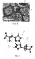
- FIG. 3 shows the TEM image 18.
- the person conducting the measurement observes the TEM image, and selects the microcrystal to be a target of the specifying process of the crystal structure. For example, a microcrystal of a portion shown by a circle 20 in the TEM image 18 was selected. The microcrystal had a size of about 1 ⁇ m.
- the electron beam was irradiated to the microcrystal by the transmission electron microscope 12, and, while the specimen was continuously rotated, a sequence of diffraction patterns were obtained.
- a three-dimensional reciprocal lattice was obtained by analyzing five diffraction patterns from the crystal.
- the direct method the structure analysis was executed based on the three-dimensional reciprocal lattice, and a potential map 22 as shown in FIG. 4 was obtained. These analyses are executed by, for example, the analysis apparatus 16.
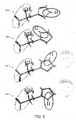
- FIGs. 5 to 7 show conformations obtained from the electron diffraction.
- FIG. 5 shows conformations 24A ⁇ 24D
- FIG. 6 shows conformations 26A ⁇ 26D
- FIG. 7 shows conformations 28A ⁇ 28D.
- the NMR parameter of the specimen was measured by the NMR apparatus 14.
- a 1H/14N correlation NMR measurement was executed. With this measurement, it was found that the orthorhombic L-histidine was a Zwitterion, and the hydrogen atom is bonded to only one of the two nitrogen atoms included in the imidazole ring (refer to Acta Cryst. (2017), C73, 219-228).
- measurement of the isotropic chemical shift of 1H, 13C, and 14N, and measurement of the interatomic distance between 1H and 15N were executed.
- the order of the electron diffraction and the NMR measurement is not particularly limited, and one of these processes may be executed before the other, or both processes may be executed at the same timing.
- the quantum chemical calculation was applied to the conformations 24A ⁇ 24D, to calculate energy and chemical shift for each of the conformations 24A ⁇ 24D.
- the chemical shift obtained by the calculation and the chemical shift obtained by the solid-state NMR measurement were compared to each other, and RMSDs (Root Mean Square Deviation) of these chemical shifts were calculated. The calculations were executed by the analysis apparatus 16.
- FIG. 8 shows the RMSD of the chemical shift for each conformation.
- FIG. 9 shows the calculated energy of each conformation.
- a horizontal axis shows the conformation
- a vertical axis shows the calculated RMSD.
- a horizontal axis shows the conformation
- a vertical axis shows the calculated energy.
- FIG. 8 shows the RMSD of the chemical shift for 13C, the RMSD of the chemical shift for 1H (proton), and the RMSD of the chemical shift for 15N.
- reference numerals 30, 32, and 34 show RMSDs of the chemical shift for the conformation 24A.
- Reference numeral 30 shows the RMSD of the chemical shift for 13C
- reference numeral 32 shows the RMSD of the chemical shift for 1H
- reference numeral 34 shows the RMSD of the chemical shift for 15N.
- the RMSDs of the chemical shifts are shown in the order of 13C, 1H, and 15N, from the left.
- the RMSD of the conformation 24A is smaller than the RMSDs of the other conformations. This indicates that the conformation 24A is the most likely structure.
- the energy of the conformation 24A is smaller than the energies of the other conformations. This indicates that the conformation 24A is the most stable structure.
- the distance between 1H and 15N obtained by the quantum chemical calculation for the conformation 24A closely matches the distance obtained by the solid-state NMR measurement (that is, the actual measured value). According to the evaluation described above, the conformation 24A is specified as the most likely structure of the specimen.
- the comparison of the RMSD, the comparison of the energy, the comparison of the interatomic distance, and the determination of the most likely structure may be executed by the analysis apparatus 16 or by the person conducting measurement.
- the graph of RMSD ( FIG. 8 ) and the graph of the energy ( FIG. 9 ) may be generated by the analysis apparatus 16 and displayed on the display, and the person conducting measurement may specify the most likely structure by referring to these graphs.
- the quantum chemical calculation is used.
- the quantum chemical calculation does not need to be employed.
- the quantum chemical calculation does not need to be executed.
- the most likely structure can be specified by the position of the hydrogen atom, and the NMR parameters such as the position of the NMR peak and the chemical shift, and, in this case, the quantum chemical calculation is not necessary.
- the crystal structure can be specified even for a crystal having a size of less than or equal to 1 ⁇ m. Therefore, the crystal structure can be specified even for a specimen for which creating a large crystal is difficult.
- a specimen with a thin thickness may be used so that the electron beam can easily transmit through the specimen.
- a specimen having a thickness of greater than or equal to 3 ⁇ m it may be difficult for the electron beam to transmit through, in which case a thinner specimen may be used.
- the overall structure of a minute crystal having a size of less than or equal to 1 ⁇ m can be specified by applying the electron diffraction method. This is because, as the interaction of the electron beam is significantly stronger than the interaction of the X-ray, a diffraction pattern can be obtained even from such a very small microcrystal.
- the position of the hydrogen atom which cannot be specified by the electron diffraction can be specified.
- the solid-state NMR measurement and the quantum chemical calculation as necessary
- elements having atomic numbers close to each other and which cannot be distinguished by the electron diffraction in the Example, the carbon atom, the nitrogen atom, and the oxygen atom
- the structure of the small crystal can be optimized.
- a small monocrystal may be selected from the specimen, and the selected monocrystal may be analyzed, to specify the structure thereof.
- the orthorhombic L-histidine was used as the specimen, but this is only exemplary, and, even for other specimens, the most likely crystal structure can be specified by the combination of the electron diffraction and the NMR measurement or by the combination of the electron diffraction, the NMR measurement, and the quantum chemical calculation.
- specimens having a high crystallinity such as an MOF (metal organic framework)
- specimens for which creating a large monocrystal is difficult and specimens having impurities such as tablets of a pharmaceutical drug may be employed as the specimen of the present embodiment.
- the crystal structure of these specimen cannot be specified by the powder X-ray diffraction method or the microcrystalline X-ray diffraction method of the related art, but according to the present embodiment, the crystal structure of these specimen can be specified.
Landscapes
- Physics & Mathematics (AREA)
- Chemical & Material Sciences (AREA)
- Life Sciences & Earth Sciences (AREA)
- Health & Medical Sciences (AREA)
- Immunology (AREA)
- Pathology (AREA)
- High Energy & Nuclear Physics (AREA)
- Analytical Chemistry (AREA)
- Biochemistry (AREA)
- General Health & Medical Sciences (AREA)
- General Physics & Mathematics (AREA)
- Crystallography & Structural Chemistry (AREA)
- Environmental & Geological Engineering (AREA)
- Engineering & Computer Science (AREA)
- General Life Sciences & Earth Sciences (AREA)
- Geochemistry & Mineralogy (AREA)
- Geology (AREA)
- Spectroscopy & Molecular Physics (AREA)
- Molecular Biology (AREA)
- Analysing Materials By The Use Of Radiation (AREA)
Applications Claiming Priority (1)
| Application Number | Priority Date | Filing Date | Title |
|---|---|---|---|
| JP2018123904A JP7088507B2 (ja) | 2018-06-29 | 2018-06-29 | 結晶構造解析システム及び結晶構造解析方法 |
Publications (3)
| Publication Number | Publication Date |
|---|---|
| EP3588069A2 true EP3588069A2 (de) | 2020-01-01 |
| EP3588069A3 EP3588069A3 (de) | 2020-01-29 |
| EP3588069B1 EP3588069B1 (de) | 2024-11-13 |
Family
ID=67314585
Family Applications (1)
| Application Number | Title | Priority Date | Filing Date |
|---|---|---|---|
| EP19182622.1A Active EP3588069B1 (de) | 2018-06-29 | 2019-06-26 | Kristallstrukturanalysesystem und kristallstrukturanalyseverfahren |
Country Status (3)
| Country | Link |
|---|---|
| US (1) | US10955366B2 (de) |
| EP (1) | EP3588069B1 (de) |
| JP (1) | JP7088507B2 (de) |
Families Citing this family (1)
| Publication number | Priority date | Publication date | Assignee | Title |
|---|---|---|---|---|
| US11988618B2 (en) * | 2021-03-31 | 2024-05-21 | Fei Company | Method and system to determine crystal structure |
Citations (1)
| Publication number | Priority date | Publication date | Assignee | Title |
|---|---|---|---|---|
| JP2005250721A (ja) | 2004-03-03 | 2005-09-15 | Hitachi High-Technologies Corp | 蛋白質または高分子複合体の検索・照合方法及び装置 |
Family Cites Families (4)
| Publication number | Priority date | Publication date | Assignee | Title |
|---|---|---|---|---|
| JP5031605B2 (ja) | 2008-01-30 | 2012-09-19 | 新日本製鐵株式会社 | 核磁気共鳴スペクトルの帰属方法 |
| JP5536085B2 (ja) * | 2008-11-06 | 2014-07-02 | ナノメガス エスピーアールエル | 電子線回折による高スループット結晶構造解析のための方法及びデバイス |
| CN104105959B (zh) * | 2012-02-06 | 2016-06-29 | 国立大学法人京都大学 | 微晶结构分析装置、微晶结构分析方法和x射线遮蔽装置 |
| WO2015072982A1 (en) | 2013-11-13 | 2015-05-21 | Heider Elizabeth M | Nmr crystallography methods for three-dimensional structure determination |
-
2018
- 2018-06-29 JP JP2018123904A patent/JP7088507B2/ja active Active
-
2019
- 2019-06-26 EP EP19182622.1A patent/EP3588069B1/de active Active
- 2019-06-28 US US16/456,166 patent/US10955366B2/en active Active
Patent Citations (1)
| Publication number | Priority date | Publication date | Assignee | Title |
|---|---|---|---|---|
| JP2005250721A (ja) | 2004-03-03 | 2005-09-15 | Hitachi High-Technologies Corp | 蛋白質または高分子複合体の検索・照合方法及び装置 |
Non-Patent Citations (1)
| Title |
|---|
| ACTA CRYST., vol. C73, 2017, pages 219 - 228 |
Also Published As
| Publication number | Publication date |
|---|---|
| US20200003710A1 (en) | 2020-01-02 |
| JP7088507B2 (ja) | 2022-06-21 |
| EP3588069B1 (de) | 2024-11-13 |
| EP3588069A3 (de) | 2020-01-29 |
| US10955366B2 (en) | 2021-03-23 |
| JP2020003375A (ja) | 2020-01-09 |
Similar Documents
| Publication | Publication Date | Title |
|---|---|---|
| Clabbers et al. | Electron diffraction data processing with DIALS | |
| Dawson et al. | Use of a CCD diffractometer in crystal structure determinations at high pressure | |
| Oddershede et al. | Determining grain resolved stresses in polycrystalline materials using three-dimensional X-ray diffraction | |
| Sauter | XFEL diffraction: developing processing methods to optimize data quality | |
| US20250012742A1 (en) | Methods and apparatus for electron backscatter diffraction sample characterisation | |
| Wenk et al. | Rietveld texture analysis of Dabie Shan eclogite from TOF neutron diffraction spectra | |
| Wojdyla et al. | Fast two-dimensional grid and transmission X-ray microscopy scanning methods for visualizing and characterizing protein crystals | |
| WO2009155440A1 (en) | Methods and apparatuses to align energy beam to atom probe specimen | |
| Ren et al. | On-the-fly data assessment for high-throughput X-ray diffraction measurements | |
| Lassen | Automated determination of crystal orientations from electron backscattering patterns | |
| CN115598156A (zh) | 使用电子通道图案确定切角 | |
| Yano et al. | Status of the neutron time-of-flight single-crystal diffraction data-processing software STARGazer | |
| EP3588069B1 (de) | Kristallstrukturanalysesystem und kristallstrukturanalyseverfahren | |
| JP6503145B2 (ja) | 置換サイト計測装置および置換サイト計測方法 | |
| US12306119B2 (en) | Methods and systems for determining the absolute structure of crystal | |
| US20120089349A1 (en) | Method for Measuring the Orientation and the Elastic Strain of Grains in Polycrystalline Materials | |
| Ångström et al. | Accurate lattice-parameter determination from electron diffraction tomography data using two-dimensional diffraction vectors | |
| Tischler | Reconstructing 2D and 3D X-ray orientation maps from white-beam Laue | |
| Ma et al. | A global optimization approach to automated indexing of fiber diffraction patterns | |
| Smilgies et al. | indexGIXS–software for visualizing and interactive indexing of grazing-incidence scattering data | |
| Zheng et al. | Automated data collection for electron microscopic tomography | |
| Vlahakis et al. | Accounting for electron-beam-induced warping of molecular nanocrystals in MicroED structure determination | |
| Haubold | Application of X-ray diffuse scattering to structure determinations of point-defects | |
| Yang et al. | HRTex: a high-resolution texture data processing tool for monochromatic neutron diffraction based on the pixel projection method | |
| Leonardi et al. | The moving-beam diffraction geometry: the DIAD application of a diffraction scanning probe |
Legal Events
| Date | Code | Title | Description |
|---|---|---|---|
| PUAI | Public reference made under article 153(3) epc to a published international application that has entered the european phase |
Free format text: ORIGINAL CODE: 0009012 |
|
| STAA | Information on the status of an ep patent application or granted ep patent |
Free format text: STATUS: THE APPLICATION HAS BEEN PUBLISHED |
|
| PUAL | Search report despatched |
Free format text: ORIGINAL CODE: 0009013 |
|
| AK | Designated contracting states |
Kind code of ref document: A2 Designated state(s): AL AT BE BG CH CY CZ DE DK EE ES FI FR GB GR HR HU IE IS IT LI LT LU LV MC MK MT NL NO PL PT RO RS SE SI SK SM TR |
|
| AX | Request for extension of the european patent |
Extension state: BA ME |
|
| AK | Designated contracting states |
Kind code of ref document: A3 Designated state(s): AL AT BE BG CH CY CZ DE DK EE ES FI FR GB GR HR HU IE IS IT LI LT LU LV MC MK MT NL NO PL PT RO RS SE SI SK SM TR |
|
| AX | Request for extension of the european patent |
Extension state: BA ME |
|
| RIC1 | Information provided on ipc code assigned before grant |
Ipc: G01N 24/08 20060101ALI20191220BHEP Ipc: G01N 23/20058 20180101ALI20191220BHEP Ipc: G01N 23/20 20180101AFI20191220BHEP |
|
| STAA | Information on the status of an ep patent application or granted ep patent |
Free format text: STATUS: REQUEST FOR EXAMINATION WAS MADE |
|
| 17P | Request for examination filed |
Effective date: 20200722 |
|
| RBV | Designated contracting states (corrected) |
Designated state(s): AL AT BE BG CH CY CZ DE DK EE ES FI FR GB GR HR HU IE IS IT LI LT LU LV MC MK MT NL NO PL PT RO RS SE SI SK SM TR |
|
| RIC1 | Information provided on ipc code assigned before grant |
Ipc: G01N 24/08 20060101ALI20220513BHEP Ipc: G01N 23/20058 20180101ALI20220513BHEP Ipc: G01N 23/20 20180101AFI20220513BHEP |
|
| STAA | Information on the status of an ep patent application or granted ep patent |
Free format text: STATUS: EXAMINATION IS IN PROGRESS |
|
| 17Q | First examination report despatched |
Effective date: 20220627 |
|
| GRAP | Despatch of communication of intention to grant a patent |
Free format text: ORIGINAL CODE: EPIDOSNIGR1 |
|
| STAA | Information on the status of an ep patent application or granted ep patent |
Free format text: STATUS: GRANT OF PATENT IS INTENDED |
|
| INTG | Intention to grant announced |
Effective date: 20240628 |
|
| GRAS | Grant fee paid |
Free format text: ORIGINAL CODE: EPIDOSNIGR3 |
|
| GRAA | (expected) grant |
Free format text: ORIGINAL CODE: 0009210 |
|
| STAA | Information on the status of an ep patent application or granted ep patent |
Free format text: STATUS: THE PATENT HAS BEEN GRANTED |
|
| AK | Designated contracting states |
Kind code of ref document: B1 Designated state(s): AL AT BE BG CH CY CZ DE DK EE ES FI FR GB GR HR HU IE IS IT LI LT LU LV MC MK MT NL NO PL PT RO RS SE SI SK SM TR |
|
| RAP3 | Party data changed (applicant data changed or rights of an application transferred) |
Owner name: JEOL LTD. Owner name: RIKEN |
|
| REG | Reference to a national code |
Ref country code: GB Ref legal event code: FG4D |
|
| REG | Reference to a national code |
Ref country code: CH Ref legal event code: EP |
|
| REG | Reference to a national code |
Ref country code: DE Ref legal event code: R096 Ref document number: 602019061827 Country of ref document: DE |
|
| REG | Reference to a national code |
Ref country code: IE Ref legal event code: FG4D |
|
| REG | Reference to a national code |
Ref country code: LT Ref legal event code: MG9D |
|
| REG | Reference to a national code |
Ref country code: NL Ref legal event code: MP Effective date: 20241113 |
|
| PG25 | Lapsed in a contracting state [announced via postgrant information from national office to epo] |
Ref country code: PT Free format text: LAPSE BECAUSE OF FAILURE TO SUBMIT A TRANSLATION OF THE DESCRIPTION OR TO PAY THE FEE WITHIN THE PRESCRIBED TIME-LIMIT Effective date: 20250313 Ref country code: IS Free format text: LAPSE BECAUSE OF FAILURE TO SUBMIT A TRANSLATION OF THE DESCRIPTION OR TO PAY THE FEE WITHIN THE PRESCRIBED TIME-LIMIT Effective date: 20250313 Ref country code: HR Free format text: LAPSE BECAUSE OF FAILURE TO SUBMIT A TRANSLATION OF THE DESCRIPTION OR TO PAY THE FEE WITHIN THE PRESCRIBED TIME-LIMIT Effective date: 20241113 |
|
| PG25 | Lapsed in a contracting state [announced via postgrant information from national office to epo] |
Ref country code: FI Free format text: LAPSE BECAUSE OF FAILURE TO SUBMIT A TRANSLATION OF THE DESCRIPTION OR TO PAY THE FEE WITHIN THE PRESCRIBED TIME-LIMIT Effective date: 20241113 Ref country code: NL Free format text: LAPSE BECAUSE OF FAILURE TO SUBMIT A TRANSLATION OF THE DESCRIPTION OR TO PAY THE FEE WITHIN THE PRESCRIBED TIME-LIMIT Effective date: 20241113 |
|
| REG | Reference to a national code |
Ref country code: AT Ref legal event code: MK05 Ref document number: 1742027 Country of ref document: AT Kind code of ref document: T Effective date: 20241113 |
|
| PG25 | Lapsed in a contracting state [announced via postgrant information from national office to epo] |
Ref country code: BG Free format text: LAPSE BECAUSE OF FAILURE TO SUBMIT A TRANSLATION OF THE DESCRIPTION OR TO PAY THE FEE WITHIN THE PRESCRIBED TIME-LIMIT Effective date: 20241113 |
|
| PG25 | Lapsed in a contracting state [announced via postgrant information from national office to epo] |
Ref country code: ES Free format text: LAPSE BECAUSE OF FAILURE TO SUBMIT A TRANSLATION OF THE DESCRIPTION OR TO PAY THE FEE WITHIN THE PRESCRIBED TIME-LIMIT Effective date: 20241113 |
|
| PG25 | Lapsed in a contracting state [announced via postgrant information from national office to epo] |
Ref country code: NO Free format text: LAPSE BECAUSE OF FAILURE TO SUBMIT A TRANSLATION OF THE DESCRIPTION OR TO PAY THE FEE WITHIN THE PRESCRIBED TIME-LIMIT Effective date: 20250213 |
|
| PG25 | Lapsed in a contracting state [announced via postgrant information from national office to epo] |
Ref country code: LV Free format text: LAPSE BECAUSE OF FAILURE TO SUBMIT A TRANSLATION OF THE DESCRIPTION OR TO PAY THE FEE WITHIN THE PRESCRIBED TIME-LIMIT Effective date: 20241113 Ref country code: GR Free format text: LAPSE BECAUSE OF FAILURE TO SUBMIT A TRANSLATION OF THE DESCRIPTION OR TO PAY THE FEE WITHIN THE PRESCRIBED TIME-LIMIT Effective date: 20250214 Ref country code: AT Free format text: LAPSE BECAUSE OF FAILURE TO SUBMIT A TRANSLATION OF THE DESCRIPTION OR TO PAY THE FEE WITHIN THE PRESCRIBED TIME-LIMIT Effective date: 20241113 |
|
| PG25 | Lapsed in a contracting state [announced via postgrant information from national office to epo] |
Ref country code: PL Free format text: LAPSE BECAUSE OF FAILURE TO SUBMIT A TRANSLATION OF THE DESCRIPTION OR TO PAY THE FEE WITHIN THE PRESCRIBED TIME-LIMIT Effective date: 20241113 |
|
| PG25 | Lapsed in a contracting state [announced via postgrant information from national office to epo] |
Ref country code: RS Free format text: LAPSE BECAUSE OF FAILURE TO SUBMIT A TRANSLATION OF THE DESCRIPTION OR TO PAY THE FEE WITHIN THE PRESCRIBED TIME-LIMIT Effective date: 20250213 |
|
| PG25 | Lapsed in a contracting state [announced via postgrant information from national office to epo] |
Ref country code: SM Free format text: LAPSE BECAUSE OF FAILURE TO SUBMIT A TRANSLATION OF THE DESCRIPTION OR TO PAY THE FEE WITHIN THE PRESCRIBED TIME-LIMIT Effective date: 20241113 |
|
| PGFP | Annual fee paid to national office [announced via postgrant information from national office to epo] |
Ref country code: DE Payment date: 20250618 Year of fee payment: 7 |
|
| PG25 | Lapsed in a contracting state [announced via postgrant information from national office to epo] |
Ref country code: DK Free format text: LAPSE BECAUSE OF FAILURE TO SUBMIT A TRANSLATION OF THE DESCRIPTION OR TO PAY THE FEE WITHIN THE PRESCRIBED TIME-LIMIT Effective date: 20241113 |
|
| PGFP | Annual fee paid to national office [announced via postgrant information from national office to epo] |
Ref country code: GB Payment date: 20250618 Year of fee payment: 7 |
|
| PG25 | Lapsed in a contracting state [announced via postgrant information from national office to epo] |
Ref country code: EE Free format text: LAPSE BECAUSE OF FAILURE TO SUBMIT A TRANSLATION OF THE DESCRIPTION OR TO PAY THE FEE WITHIN THE PRESCRIBED TIME-LIMIT Effective date: 20241113 |
|
| PGFP | Annual fee paid to national office [announced via postgrant information from national office to epo] |
Ref country code: FR Payment date: 20250626 Year of fee payment: 7 |
|
| PG25 | Lapsed in a contracting state [announced via postgrant information from national office to epo] |
Ref country code: RO Free format text: LAPSE BECAUSE OF FAILURE TO SUBMIT A TRANSLATION OF THE DESCRIPTION OR TO PAY THE FEE WITHIN THE PRESCRIBED TIME-LIMIT Effective date: 20241113 |
|
| PG25 | Lapsed in a contracting state [announced via postgrant information from national office to epo] |
Ref country code: SK Free format text: LAPSE BECAUSE OF FAILURE TO SUBMIT A TRANSLATION OF THE DESCRIPTION OR TO PAY THE FEE WITHIN THE PRESCRIBED TIME-LIMIT Effective date: 20241113 |
|
| PG25 | Lapsed in a contracting state [announced via postgrant information from national office to epo] |
Ref country code: CZ Free format text: LAPSE BECAUSE OF FAILURE TO SUBMIT A TRANSLATION OF THE DESCRIPTION OR TO PAY THE FEE WITHIN THE PRESCRIBED TIME-LIMIT Effective date: 20241113 |
|
| PG25 | Lapsed in a contracting state [announced via postgrant information from national office to epo] |
Ref country code: IT Free format text: LAPSE BECAUSE OF FAILURE TO SUBMIT A TRANSLATION OF THE DESCRIPTION OR TO PAY THE FEE WITHIN THE PRESCRIBED TIME-LIMIT Effective date: 20241113 |
|
| REG | Reference to a national code |
Ref country code: DE Ref legal event code: R097 Ref document number: 602019061827 Country of ref document: DE |
|
| PG25 | Lapsed in a contracting state [announced via postgrant information from national office to epo] |
Ref country code: SE Free format text: LAPSE BECAUSE OF FAILURE TO SUBMIT A TRANSLATION OF THE DESCRIPTION OR TO PAY THE FEE WITHIN THE PRESCRIBED TIME-LIMIT Effective date: 20241113 |
|
| PLBE | No opposition filed within time limit |
Free format text: ORIGINAL CODE: 0009261 |
|
| STAA | Information on the status of an ep patent application or granted ep patent |
Free format text: STATUS: NO OPPOSITION FILED WITHIN TIME LIMIT |
|
| 26N | No opposition filed |
Effective date: 20250814 |
|
| REG | Reference to a national code |
Ref country code: CH Ref legal event code: H13 Free format text: ST27 STATUS EVENT CODE: U-0-0-H10-H13 (AS PROVIDED BY THE NATIONAL OFFICE) Effective date: 20260127 |
|
| PG25 | Lapsed in a contracting state [announced via postgrant information from national office to epo] |
Ref country code: MC Free format text: LAPSE BECAUSE OF FAILURE TO SUBMIT A TRANSLATION OF THE DESCRIPTION OR TO PAY THE FEE WITHIN THE PRESCRIBED TIME-LIMIT Effective date: 20241113 |
|
| PG25 | Lapsed in a contracting state [announced via postgrant information from national office to epo] |
Ref country code: LU Free format text: LAPSE BECAUSE OF NON-PAYMENT OF DUE FEES Effective date: 20250626 |
|
| REG | Reference to a national code |
Ref country code: BE Ref legal event code: MM Effective date: 20250630 |
|
| PG25 | Lapsed in a contracting state [announced via postgrant information from national office to epo] |
Ref country code: IE Free format text: LAPSE BECAUSE OF NON-PAYMENT OF DUE FEES Effective date: 20250626 |
|
| PG25 | Lapsed in a contracting state [announced via postgrant information from national office to epo] |
Ref country code: BE Free format text: LAPSE BECAUSE OF NON-PAYMENT OF DUE FEES Effective date: 20250630 |
|
| PG25 | Lapsed in a contracting state [announced via postgrant information from national office to epo] |
Ref country code: CH Free format text: LAPSE BECAUSE OF NON-PAYMENT OF DUE FEES Effective date: 20250630 |