EP3588013A1 - Procédé de distribution d'énergie électrique - Google Patents
Procédé de distribution d'énergie électrique Download PDFInfo
- Publication number
- EP3588013A1 EP3588013A1 EP18450006.4A EP18450006A EP3588013A1 EP 3588013 A1 EP3588013 A1 EP 3588013A1 EP 18450006 A EP18450006 A EP 18450006A EP 3588013 A1 EP3588013 A1 EP 3588013A1
- Authority
- EP
- European Patent Office
- Prior art keywords
- consumer
- delivery device
- current
- power
- clearing house
- Prior art date
- Legal status (The legal status is an assumption and is not a legal conclusion. Google has not performed a legal analysis and makes no representation as to the accuracy of the status listed.)
- Withdrawn
Links
Images

Classifications
-
- G—PHYSICS
- G01—MEASURING; TESTING
- G01D—MEASURING NOT SPECIALLY ADAPTED FOR A SPECIFIC VARIABLE; ARRANGEMENTS FOR MEASURING TWO OR MORE VARIABLES NOT COVERED IN A SINGLE OTHER SUBCLASS; TARIFF METERING APPARATUS; MEASURING OR TESTING NOT OTHERWISE PROVIDED FOR
- G01D4/00—Tariff metering apparatus
- G01D4/002—Remote reading of utility meters
-
- B—PERFORMING OPERATIONS; TRANSPORTING
- B60—VEHICLES IN GENERAL
- B60L—PROPULSION OF ELECTRICALLY-PROPELLED VEHICLES; SUPPLYING ELECTRIC POWER FOR AUXILIARY EQUIPMENT OF ELECTRICALLY-PROPELLED VEHICLES; ELECTRODYNAMIC BRAKE SYSTEMS FOR VEHICLES IN GENERAL; MAGNETIC SUSPENSION OR LEVITATION FOR VEHICLES; MONITORING OPERATING VARIABLES OF ELECTRICALLY-PROPELLED VEHICLES; ELECTRIC SAFETY DEVICES FOR ELECTRICALLY-PROPELLED VEHICLES
- B60L53/00—Methods of charging batteries, specially adapted for electric vehicles; Charging stations or on-board charging equipment therefor; Exchange of energy storage elements in electric vehicles
-
- G—PHYSICS
- G01—MEASURING; TESTING
- G01D—MEASURING NOT SPECIALLY ADAPTED FOR A SPECIFIC VARIABLE; ARRANGEMENTS FOR MEASURING TWO OR MORE VARIABLES NOT COVERED IN A SINGLE OTHER SUBCLASS; TARIFF METERING APPARATUS; MEASURING OR TESTING NOT OTHERWISE PROVIDED FOR
- G01D4/00—Tariff metering apparatus
- G01D4/002—Remote reading of utility meters
- G01D4/004—Remote reading of utility meters to a fixed location
-
- G—PHYSICS
- G01—MEASURING; TESTING
- G01D—MEASURING NOT SPECIALLY ADAPTED FOR A SPECIFIC VARIABLE; ARRANGEMENTS FOR MEASURING TWO OR MORE VARIABLES NOT COVERED IN A SINGLE OTHER SUBCLASS; TARIFF METERING APPARATUS; MEASURING OR TESTING NOT OTHERWISE PROVIDED FOR
- G01D2204/00—Indexing scheme relating to details of tariff-metering apparatus
- G01D2204/20—Monitoring; Controlling
- G01D2204/24—Identification of individual loads, e.g. by analysing current/voltage waveforms
-
- Y—GENERAL TAGGING OF NEW TECHNOLOGICAL DEVELOPMENTS; GENERAL TAGGING OF CROSS-SECTIONAL TECHNOLOGIES SPANNING OVER SEVERAL SECTIONS OF THE IPC; TECHNICAL SUBJECTS COVERED BY FORMER USPC CROSS-REFERENCE ART COLLECTIONS [XRACs] AND DIGESTS
- Y02—TECHNOLOGIES OR APPLICATIONS FOR MITIGATION OR ADAPTATION AGAINST CLIMATE CHANGE
- Y02T—CLIMATE CHANGE MITIGATION TECHNOLOGIES RELATED TO TRANSPORTATION
- Y02T10/00—Road transport of goods or passengers
- Y02T10/60—Other road transportation technologies with climate change mitigation effect
- Y02T10/70—Energy storage systems for electromobility, e.g. batteries
-
- Y—GENERAL TAGGING OF NEW TECHNOLOGICAL DEVELOPMENTS; GENERAL TAGGING OF CROSS-SECTIONAL TECHNOLOGIES SPANNING OVER SEVERAL SECTIONS OF THE IPC; TECHNICAL SUBJECTS COVERED BY FORMER USPC CROSS-REFERENCE ART COLLECTIONS [XRACs] AND DIGESTS
- Y02—TECHNOLOGIES OR APPLICATIONS FOR MITIGATION OR ADAPTATION AGAINST CLIMATE CHANGE
- Y02T—CLIMATE CHANGE MITIGATION TECHNOLOGIES RELATED TO TRANSPORTATION
- Y02T10/00—Road transport of goods or passengers
- Y02T10/60—Other road transportation technologies with climate change mitigation effect
- Y02T10/7072—Electromobility specific charging systems or methods for batteries, ultracapacitors, supercapacitors or double-layer capacitors
-
- Y—GENERAL TAGGING OF NEW TECHNOLOGICAL DEVELOPMENTS; GENERAL TAGGING OF CROSS-SECTIONAL TECHNOLOGIES SPANNING OVER SEVERAL SECTIONS OF THE IPC; TECHNICAL SUBJECTS COVERED BY FORMER USPC CROSS-REFERENCE ART COLLECTIONS [XRACs] AND DIGESTS
- Y02—TECHNOLOGIES OR APPLICATIONS FOR MITIGATION OR ADAPTATION AGAINST CLIMATE CHANGE
- Y02T—CLIMATE CHANGE MITIGATION TECHNOLOGIES RELATED TO TRANSPORTATION
- Y02T90/00—Enabling technologies or technologies with a potential or indirect contribution to GHG emissions mitigation
- Y02T90/10—Technologies relating to charging of electric vehicles
- Y02T90/14—Plug-in electric vehicles
-
- Y—GENERAL TAGGING OF NEW TECHNOLOGICAL DEVELOPMENTS; GENERAL TAGGING OF CROSS-SECTIONAL TECHNOLOGIES SPANNING OVER SEVERAL SECTIONS OF THE IPC; TECHNICAL SUBJECTS COVERED BY FORMER USPC CROSS-REFERENCE ART COLLECTIONS [XRACs] AND DIGESTS
- Y04—INFORMATION OR COMMUNICATION TECHNOLOGIES HAVING AN IMPACT ON OTHER TECHNOLOGY AREAS
- Y04S—SYSTEMS INTEGRATING TECHNOLOGIES RELATED TO POWER NETWORK OPERATION, COMMUNICATION OR INFORMATION TECHNOLOGIES FOR IMPROVING THE ELECTRICAL POWER GENERATION, TRANSMISSION, DISTRIBUTION, MANAGEMENT OR USAGE, i.e. SMART GRIDS
- Y04S20/00—Management or operation of end-user stationary applications or the last stages of power distribution; Controlling, monitoring or operating thereof
- Y04S20/30—Smart metering, e.g. specially adapted for remote reading
Definitions
- the invention relates to a method for supplying electrical energy to electrical consumers using at least one power supply device connected to a power supply network, to which an electrical consumer can be connected via a cable, the current consumption of the electrical consumer being measured and the measured current consumption being transmitted to a clearing house ,
- the invention further relates to a current delivery device, in particular for carrying out the method according to the invention, comprising a current feed connection for connecting the current delivery device to a power supply network, a current delivery connection for connecting an electrical consumer to the current delivery device, switching means for selectively enabling or interrupting the current flow from the current feed connection to the current delivery connection Measuring circuit for measuring the current consumption of the connected consumer and a control circuit for controlling the switching means.
- the invention also relates to a system for supplying electrical energy to electrical consumers, in particular for carrying out the method according to the invention, comprising a power supply device according to the invention which can be connected to a power supply network and a data processing device designed as a clearing point.
- Electricity meters When supplying electrical consumers with electrical energy or the supply of electrical energy to electrical consumers by a Energy supply companies use electricity meters to measure electricity consumption, with an electricity meter being provided for each household or billing office. The measured values of the electricity meter are read at certain intervals and transmitted to a clearing house, which debits the billing account of the participant to whom the electricity meter in question is assigned. In the case of so-called intelligent electricity meters (smart meters), the measured values can be read out remotely by the energy supply company via a data interface. Electricity meters automatically record the electricity consumption of all electrical consumers that are arranged behind the electricity meter as seen from the power supply network. In conventional systems, it is therefore not possible to record the electricity consumption of individual electrical consumers separately in the clearing house.
- the invention essentially provides in a method of the type mentioned at the outset that the consumer is assigned a consumer identifier which is transmitted via the cable to the power supply device and further to the clearing house, that the clearing house checks whether the Consumer identification is assigned to a subscriber stored in the clearing house and, if the test is positive, a release signal is transmitted to the power delivery device in order to release the power delivery by the power delivery device, a billing account assigned to the subscriber being charged with the measured power consumption.
- the invention enables the recording of the current consumption of an individual electrical consumer and the billing of the current consumption by a power supply company without the electrical consumer having to be assigned a separate electricity meter of the power supply company. Rather, it is sufficient if the current delivery device in is arranged in a power grid, in which there is a large number of electrical consumers, the total consumption of which is recorded by a single electricity meter of the power supply company. In this way, it becomes possible for private households or companies with a conventional electricity meter to arrange power delivery devices in their power network and to offer them to external participants by means of a power draw via the aforementioned power delivery devices, which is charged directly to the respective external subscriber, for example by the power supply company.
- the attribution of the power consumption to the respective subscriber is carried out according to the invention by means of a consumer recognition which is assigned to the electrical consumer connected to the power delivery device via a cable.
- the consumption recognition In order to enable electricity to be drawn, the consumption recognition must be released by the clearing house, for example by the power supply company, for which purpose the consumer recognition is transmitted to the power delivery device and from the power delivery device to the clearing house.
- the clearing house In the clearing house it is checked whether the consumer identification is assigned to a subscriber stored in the clearing house and, if the test is positive, a release signal is transmitted to the current delivery device in order to release the current delivery by the current delivery device.
- the electricity consumption of the electrical consumer is recorded by suitable measuring devices and the billing account assigned to the participant is debited with the measured electricity consumption. Based on the consumer detection assigned to the electrical consumer, the recording of the power consumption can be carried out in a consumer-specific manner Way, and this also in a power network that has an electricity meter that is assigned to another subscriber and therefore to another billing account.
- the consumption detection is particularly preferably transmitted via an electrical load profile. This allows a particularly simple and secure transmission via the cable serving the electrical energy supply of the electrical consumer.
- the charging profile can be designed as digital or analog coding of the consumer recognition.
- a charging profile includes a characteristic change in time of an electrical variable, such as understood the current consumption, the voltage or the like.
- the reading out of the consumer identification in particular the recording and evaluation of the charging profile, can take place in the power delivery device or in another device of the local power network, e.g. in the electricity meter (especially smart meter), via which the electricity network is connected to the public electricity supply network.
- the electricity meter especially smart meter
- the further transmission of the consumer identification to the clearing house can in principle take place in any manner, preferably using the one
- PSTN Public Switched Telephone Network
- UMTS Universal Mobile Telecommunications
- GSM Global System for Mobile communications
- GPRS mobile radio
- LAN local network
- PLC Powerline Communication, i.e. data transmission via the power network
- the measurement of the electricity consumption of the consumer can preferably be carried out in the electricity delivery device or in the consumer.
- the corresponding measured values are then transmitted to the clearing house.
- a particularly tamper-proof detection of the current consumption of the electrical consumer is preferably achieved by measuring the current consumption of the consumer in the current delivery device and additionally in the consumer and by comparing the current consumption measured in the current delivery device and the consumer and outputting an error message in the event of a deviation and / or the current delivery is interrupted by the current delivery device. This procedure ensures that an improper diversion of electrical energy at the expense of the subscriber in the area between the power supply device and the consumer, e.g. by interposing a multiple socket, is reliably discovered.
- a preferred embodiment provides that the current delivery device is arranged in the measuring area of an electricity meter, the measurement values of which are transmitted to the clearing house and a billing account assigned to the electricity meter is charged in accordance with the measured values, the electricity consumption of the electrical Consumer is credited to the billing account assigned to the electricity meter.
- Such a procedure ensures that the electricity consumption with which the participant is charged, to which the electrical consumer is assigned, is credited to the participant whose billing account is associated with the electricity meter, which is the electricity consumption of the entire electricity network, including the consumer connected to the electricity delivery device measures to avoid double billing.
- the electricity meter In order to ensure that the electricity consumed by the consumer is credited to the correct billing account, provision is preferably made for the electricity meter to be assigned an electricity meter identification, which is transmitted to the settlement agent together with the consumption identification.
- the transmission of the consumer identification and, if applicable, the electricity meter identification to the clearing house, in particular from the power delivery device to the clearing house, is preferably carried out via the power supply network (e.g. power line communication) or via a mobile telecommunications network.
- the power supply network e.g. power line communication
- a mobile telecommunications network e.g. a mobile telecommunications network
- the invention provides a current delivery device, in particular for carrying out the method according to the invention, comprising a current feed connection for connecting the current delivery device to a power supply network, a current delivery connection for connecting a consumer to the current delivery device, switching means for optionally enabling or interrupting the current flow from Current supply connection to the current output connection, a measuring circuit for measuring the current consumption of the connected consumer and a control circuit for controlling the switching means, the current output device having a data communication interface which is connected to the measuring circuit and the control circuit in order to exchange data between the measuring and control circuit and a clearing house , wherein the control circuit is designed to control the switching means for releasing the current flow when an enable signal is received via the data communication interface, and wherein the measuring circuit is designed to transmit power consumption measurement data via the data communication interface to the clearing house, and in that the current delivery device further comprises a decoding circuit , which is connected to the power supply connection, around a consumer received via the power supply connection and assigned to the consumer read out and transmit it to the clearing house via the
- an electronic memory that can be connected to the power supply connection of the power supply device and has stored a consumer identification is preferably provided, and transmission means for transferring the consumer identification from the electronic memory via the current output connection to the decoding circuit.
- the transmission means preferably have a load generating device, to which the consumer identification is fed from the electronic memory, so that a the load profile encoding the load identification can be generated.
- the decoding circuit is preferably connected to the measuring circuit and designed to read out an electrical load profile detected by the measuring circuit.
- the current delivery connection is preferably designed as a socket.
- the socket can e.g. be designed as IEC 62196 Type 2.
- the load generating device can preferably be integrated or interposed in a cable or its plug that can be connected to the power output connection of the power output device.
- the cable can e.g. be designed as a charging cable for an electric vehicle and be equipped with an electronic circuit which is suitable for generating the load profile and which has an electronic memory with the consumer recognition.
- the memory can already be written at the factory with a clear consumer identification, the participant having to assign the consumption identification to his billing account in an initial registration process. After registration of the consumer identification, each current draw is charged to the subscriber via the charging cable connected to a current delivery device according to the invention.
- the load generation device is integrated into the consumer is, with regard to the registration process can be carried out analogously as described above.
- a further aspect of the invention provides a system for supplying electrical energy to electrical consumers, in particular for carrying out the method according to the invention, comprising a current delivery device according to the invention that can be connected to a power supply network, a data processing device designed as a clearing point, which participants have stored consumer identifiers and clearing accounts assigned to them , at least one electronic memory which can be connected to the current delivery connection of the current delivery device and has stored a consumer identification, and transmission means for transmitting the consumer identification from the electronic memory via the current delivery connection to the decoding circuit, the current delivery device cooperating with the clearing house in such a way that the consumer identification starts from the current delivery device the clearing house is submitted to that we checked in the clearing house d whether the consumer identification is assigned to a subscriber stored in the clearing house and, if the test is positive, a release signal is transmitted to the power delivery device in order to release the power delivery by the power delivery device, the billing account assigned to the subscriber being debited with the measured power consumption.
- Fig. 1 a block diagram of the system according to the invention
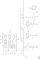
- Fig. 2 a circuit diagram of a power network in which a power delivery device according to the invention is arranged.
- Fig. 1 the clearing house of a power supply company is designated 1, which has a database in which subscribers 2 1 , 2 2 ... 2 n are stored, each of whom is assigned a clearing account 3 1 , 3 2 ... 3 n . Furthermore, the subscribers are each assigned at least one electricity meter recognition 4 1 , 4 2 ... 4 n , which identifies an electricity meter 5 1 , 5 2 ... 5 n installed at the corresponding subscriber.
- the power supply company maintains a power supply network 6, to which various buildings, households, companies or the like are connected, an electricity meter 5 1 , 5 2 ... 5 n being interposed in each case in order to measure the power consumption of the power network 7 1 , 7 2 located behind it ... 7 n of the participant.
- the electricity meters 5 1 , 5 2 ... 5 n are preferably designed as intelligent electricity meters (smart meters) so that the measured electricity consumption can be transmitted to the clearing house 1 via a schematically illustrated data communication connection 8.
- the electricity meter 5 also transmits the electricity meter recognition 4 assigned to it, so that the electricity meter measurement data obtained in the clearing house 1 can be assigned to the corresponding subscriber 2.
- a power delivery device 9 according to the invention is now (among other things) connected to the power network 7 1 .
- the subscriber 2 1 who is in a contractual relationship with the electricity supply company with respect to the electricity meter 5 1 , is generally obliged to bear the costs incurred for the electricity consumption of his electricity network 7 1 .
- the current delivery device 9 enables the subscriber 2 1 to allow other subscribers to connect electrical consumers to his power supply network 7 1 without the billing account 3 1 of the subscriber 2 1 being charged with the corresponding costs.
- An electrical consumer 10 is connected to the current delivery device 9, to which a consumer identification 11 2 is assigned, which is assigned to the subscriber 2 2 in the database of the clearing center. As will be described in more detail below, this leads to the fact that the electricity costs caused by the electrical consumer 10 are not charged to subscriber 2 1 but to subscriber 2 2 .
- the electrical consumer 10 is connected to the current delivery device 9 via a cable 12, the consumer identifier 11 2 being transmitted to the current delivery device 9 via the cable 12 in the event of a power requirement.
- the consumer identification 11 2 can then either be transmitted directly from the electricity delivery device 9 via a data communication link 13 to the clearing house 1 or forwarded to the electricity meter 5 1 and transmitted from there to the clearing house 1.
- the clearing house 1 it is checked whether the consumer identification 11 2 is assigned to a subscriber stored in the clearing house 1, in which In the present example, the subscriber 2 2 is identified, and if the test is positive, an enable signal is transmitted to the power supply device 9 via the data communication link 8 or 13 in order to enable the power supply to be released by the power supply device 9.
- the current consumer of the electrical consumer 10 is subsequently of a current measuring device (in Fig. 1 not shown) recorded and transmitted to the clearing house 1, the clearing account 3 2 assigned to the subscriber 2 2 being charged with the measured power consumption.
- the billing account 3 1 of the participant 2 is credited with the measured power consumption.
- the power supply network comprises the phase conductors 14, 15, 16, a neutral conductor 17 and the grounding 18.
- the electricity meter 5 1 is connected to the phase conductors 14, 15, 16 and to the neutral conductor 17 in order to measure the current consumption occurring behind the electricity meter 5 1 in the electricity network 7 1 .
- a power delivery device 9 according to the invention and a further power delivery device 19 according to the invention are connected to the power network 7 1 .
- the power delivery devices 9 and 19 each comprise a power outlet 20 or 21 on the power delivery side, which allow the connection of a consumer 10.
- the socket 21 can, in addition to connections for three phase conductors, a neutral conductor and the grounding, a PP contact 22 (proximity pilot) for the presence of the plug, and include a CP contact 23 (Control Pilot) to exchange the necessary control signals between the electric vehicle and the current delivery device 19 acting as a charging station.
- a PP contact 22 proximity pilot
- CP contact 23 Control Pilot
- the example of the current delivery device 9 now shows that a charging cable 12 is connected to the socket 20, which has a plug 24 on the vehicle side for the charging socket of the vehicle.
- the cable 12 is equipped with an electronic circuit 25, which comprises a memory for a consumer identification 11 2 and a load generating device, to which the consumer identification 11 2 is supplied from the electronic memory, so that a load profile encoding the consumer identification can be generated.
- the load generating device is connected to the three phase conductors of the cable 12 via a delta circuit 26.
- the load profile generated can be detected by means of a measuring and control circuit 27 of the current delivery device 9.
- the measuring and control circuit 27 comprises a decoding circuit for reading out an electrical load profile detected by the measuring and control circuit 27.
- the consumer identification 11 2 is transmitted to the measuring and control circuit 27 and from there via the data communication interface 29 and via the data communication connection 8 or 13 to the clearing house 1.
- the measuring and control circuit 27 releases the current flow from the power network 7 1 via the current delivery device 9 to the socket 20, so that the charging process can begin.
- the measurement and control circuit 27 is coupled via an inductive measurement connection 28 to the three phase conductors, so that the current consumed by the electrical consumer 10 is detected and subsequently together with the consumer detection 11 2 and the electricity meter identifier is transmitted to the clearing house 1 4. 1
- the transmission of the consumption identification 11 2 and the electricity meter identification 4 1 allows the clearing house 1 to charge the settlement account 3 2 of the participant 2 2 , to which the consumption identification 11 2 is assigned, with the corresponding electricity consumption and the electricity consumption to the settlement account 3 1 of the participant 2 1 to which the electricity meter recognition 4 1 is assigned.
Priority Applications (3)
| Application Number | Priority Date | Filing Date | Title |
|---|---|---|---|
| EP18450006.4A EP3588013A1 (fr) | 2018-06-26 | 2018-06-26 | Procédé de distribution d'énergie électrique |
| PCT/AT2019/000018 WO2020000001A1 (fr) | 2018-06-26 | 2019-06-25 | Procédé de distribution d'énergie électrique |
| EP19733652.2A EP3814721A1 (fr) | 2018-06-26 | 2019-06-25 | Procédé de distribution d'énergie électrique |
Applications Claiming Priority (1)
| Application Number | Priority Date | Filing Date | Title |
|---|---|---|---|
| EP18450006.4A EP3588013A1 (fr) | 2018-06-26 | 2018-06-26 | Procédé de distribution d'énergie électrique |
Publications (1)
| Publication Number | Publication Date |
|---|---|
| EP3588013A1 true EP3588013A1 (fr) | 2020-01-01 |
Family
ID=63207699
Family Applications (2)
| Application Number | Title | Priority Date | Filing Date |
|---|---|---|---|
| EP18450006.4A Withdrawn EP3588013A1 (fr) | 2018-06-26 | 2018-06-26 | Procédé de distribution d'énergie électrique |
| EP19733652.2A Withdrawn EP3814721A1 (fr) | 2018-06-26 | 2019-06-25 | Procédé de distribution d'énergie électrique |
Family Applications After (1)
| Application Number | Title | Priority Date | Filing Date |
|---|---|---|---|
| EP19733652.2A Withdrawn EP3814721A1 (fr) | 2018-06-26 | 2019-06-25 | Procédé de distribution d'énergie électrique |
Country Status (2)
| Country | Link |
|---|---|
| EP (2) | EP3588013A1 (fr) |
| WO (1) | WO2020000001A1 (fr) |
Families Citing this family (24)
| Publication number | Priority date | Publication date | Assignee | Title |
|---|---|---|---|---|
| US7833250B2 (en) | 2004-11-10 | 2010-11-16 | Jackson Roger P | Polyaxial bone screw with helically wound capture connection |
| US9199022B2 (en) | 2008-09-12 | 2015-12-01 | Fresenius Medical Care Holdings, Inc. | Modular reservoir assembly for a hemodialysis and hemofiltration system |
| US8105487B2 (en) | 2007-09-25 | 2012-01-31 | Fresenius Medical Care Holdings, Inc. | Manifolds for use in conducting dialysis |
| US8101706B2 (en) | 2008-01-11 | 2012-01-24 | Serina Therapeutics, Inc. | Multifunctional forms of polyoxazoline copolymers and drug compositions comprising the same |
| AU2010238752B2 (en) | 2009-04-22 | 2014-05-29 | Nevro Corporation | Spinal cord modulation for inducing paresthetic and anesthetic effects, and associated systems and methods |
| US11229457B2 (en) | 2009-06-15 | 2022-01-25 | Roger P. Jackson | Pivotal bone anchor assembly with insert tool deployment |
| US9268912B2 (en) | 2010-04-12 | 2016-02-23 | Cerx Pharmacy Partners, Lp | On site prescription management system and methods for health care facilities |
| MX2020011870A (es) | 2012-05-25 | 2022-11-07 | Derrick Corp | Aparatos y métodos de filtros moldeados de inyección. |
| EP2887952B1 (fr) | 2012-08-21 | 2019-05-15 | Janssen Pharmaceutica NV | Anticorps dirigés contre des haptènes d'olanzapine et leur utilisation |
| US9157786B2 (en) | 2012-12-24 | 2015-10-13 | Fresenius Medical Care Holdings, Inc. | Load suspension and weighing system for a dialysis machine reservoir |
| EP2928402B1 (fr) | 2013-03-15 | 2017-05-03 | Gyrus Acmi, Inc. | Dispositif électrochirurgical combiné |
| RS63583B1 (sr) | 2014-01-10 | 2022-10-31 | Bioverativ Therapeutics Inc | Himerni proteini faktora viii i njihova upotreba |
| TWI721947B (zh) | 2014-06-11 | 2021-03-21 | 美商基利法瑪席特有限責任公司 | 抗病毒化合物的固態形式 |
| BR112017008530B1 (pt) | 2014-10-31 | 2022-10-18 | Hewlett-Packard Development Company, L.P | Método para operar um dispositivo de ejeção de fluido e dispositivo de ejeção de fluido |
| GB2553681B (en) | 2015-01-07 | 2019-06-26 | Homeserve Plc | Flow detection device |
| EP3449056B1 (fr) | 2016-04-29 | 2021-12-08 | Stora Enso Oyj | Film comprenant de la cellulose microfibrillée et produits fabriqués à partir de celui-ci |
| WO2018104894A1 (fr) | 2016-12-07 | 2018-06-14 | Auckland Uniservices Limited | Système de stimulus et de suivi oculaire |
| US10469379B2 (en) | 2017-02-17 | 2019-11-05 | Cisco Technology, Inc. | System and method to facilitate content delivery to multiple recipients in a network environment |
| US11197204B2 (en) | 2017-06-23 | 2021-12-07 | British Telecommunications Public Limited Company | Voice service handover |
| US11225191B2 (en) | 2017-06-28 | 2022-01-18 | Honda Motor Co., Ltd. | Smart leather with wireless power |
| JP7326261B2 (ja) | 2017-10-20 | 2023-08-15 | ユニリーバー・アイピー・ホールディングス・ベスローテン・ヴェンノーツハップ | 髪のボリュームを減らす方法 |
| US10560898B1 (en) | 2019-05-30 | 2020-02-11 | Snap Inc. | Wearable device location systems |
| US11208986B2 (en) | 2019-06-27 | 2021-12-28 | Uptake Technologies, Inc. | Computer system and method for detecting irregular yaw activity at a wind turbine |
| DE102022207265B3 (de) | 2022-07-15 | 2023-11-30 | Robert Bosch Gesellschaft mit beschränkter Haftung | Verfahren zum Bereitstellen von Daten zum Prüfen eines Ladevorgangs eines Fahrzeugs, Verfahren zum Prüfen eines Ladevorgangs eines Fahrzeugs, Ladekabel, Recheneinheit und Computerprogramm |
Citations (5)
| Publication number | Priority date | Publication date | Assignee | Title |
|---|---|---|---|---|
| DE102006002840A1 (de) * | 2006-01-19 | 2007-08-02 | Protec Energy Gmbh & Co. Kg | Mess- und Abgabevorrichtung für Verbrauchsmittel mit Fernsteuerungs-Funktionalität |
| DE102010019376A1 (de) * | 2010-05-04 | 2011-11-10 | Heinz Schildgen | Stromzählersystem und Verfahren zur Freigabe einer Stromentnahmevorrichtung |
| US20120330494A1 (en) * | 2011-05-26 | 2012-12-27 | Hendrix Walter M | Electric vehicle fleet charging system |
| EP2597426A1 (fr) * | 2011-11-25 | 2013-05-29 | ubitricity Gesellschaft für verteilte Energiesysteme mbH | Système de point de calcul et de mesure et calcul d'énergie électrique/électricité ainsi que procédé |
| US20140114448A1 (en) * | 2012-10-19 | 2014-04-24 | Chris Outwater | Method and apparatus for sharing electric vehicle and electric appliance usage data |
-
2018
- 2018-06-26 EP EP18450006.4A patent/EP3588013A1/fr not_active Withdrawn
-
2019
- 2019-06-25 EP EP19733652.2A patent/EP3814721A1/fr not_active Withdrawn
- 2019-06-25 WO PCT/AT2019/000018 patent/WO2020000001A1/fr active Search and Examination
Patent Citations (5)
| Publication number | Priority date | Publication date | Assignee | Title |
|---|---|---|---|---|
| DE102006002840A1 (de) * | 2006-01-19 | 2007-08-02 | Protec Energy Gmbh & Co. Kg | Mess- und Abgabevorrichtung für Verbrauchsmittel mit Fernsteuerungs-Funktionalität |
| DE102010019376A1 (de) * | 2010-05-04 | 2011-11-10 | Heinz Schildgen | Stromzählersystem und Verfahren zur Freigabe einer Stromentnahmevorrichtung |
| US20120330494A1 (en) * | 2011-05-26 | 2012-12-27 | Hendrix Walter M | Electric vehicle fleet charging system |
| EP2597426A1 (fr) * | 2011-11-25 | 2013-05-29 | ubitricity Gesellschaft für verteilte Energiesysteme mbH | Système de point de calcul et de mesure et calcul d'énergie électrique/électricité ainsi que procédé |
| US20140114448A1 (en) * | 2012-10-19 | 2014-04-24 | Chris Outwater | Method and apparatus for sharing electric vehicle and electric appliance usage data |
Also Published As
| Publication number | Publication date |
|---|---|
| EP3814721A1 (fr) | 2021-05-05 |
| WO2020000001A1 (fr) | 2020-01-02 |
Similar Documents
| Publication | Publication Date | Title |
|---|---|---|
| EP3588013A1 (fr) | Procédé de distribution d'énergie électrique | |
| EP2445745B1 (fr) | Determination de quantité d'énergie recu | |
| EP2756982B1 (fr) | Procédé et système d'échange d'informations de charge entre une station de charge et un système de caisse | |
| EP2192386B2 (fr) | Système de point de calcul et de mesure et calcul d'énergie électrique ainsi que procédé | |
| DE102009026936B4 (de) | Vorrichtung zum Anschluss an ein elektrisches Energieversorgungsnetz und Transportsystem | |
| EP2326529A1 (fr) | Dispositif de commande de station service électrique pour le ravitaillement en courant d'une unité mobile d'accumulation et de consommation et/ou la réinjection de courant dans le réseau à partir de cette unité mobile | |
| EP2258582A2 (fr) | Système et procédé de charge de véhicules électriques | |
| WO2011039284A2 (fr) | Système et procédé pour surveiller un transfert d'énergie entre une première et une deuxième unité énergétique | |
| DE102011013453A1 (de) | Energieverteilnetz für mit Akkus versehenen Elektroautos | |
| WO2011154218A2 (fr) | Contrôle d'accès à des stations de recharge électrique | |
| DE102010009583A1 (de) | Verfahren zum ortsunabhängigen Strombezug und/oder zur ortsunabhängigen Stromeinspeisung einer mobilen Speicher- und Verbrauchseinheit an einer ortsfesten Stromtankstelle eines beliebigen Betreibers | |
| EP2704918A2 (fr) | Procédé pour détecter un milieu de volume déterminable et transférable d'une première unité à une deuxième unité | |
| EP2371611B1 (fr) | Dispositif et procédé d'échange d'énergie contrôlé entre un secteur et un consommateur | |
| DE102010019376A1 (de) | Stromzählersystem und Verfahren zur Freigabe einer Stromentnahmevorrichtung | |
| EP3453560A1 (fr) | Procédé et dispositif pour un échange d'énergie électrique | |
| WO2012038225A2 (fr) | Procédé de charge d'au moins un dispositif de stockage d'énergie d'un véhicule électrique | |
| DE102018201698A1 (de) | Verfahren zum Betreiben eines Ladekabels, Verfahren zum Betreiben einer Ladeinfrastruktur sowie Ladekabel | |
| EP2668470B1 (fr) | Procédé pour injecter de l'énergie dans un réseau fournisseur d'énergie | |
| DE102009042330A1 (de) | Vorrichtung und ein Verfahren zum automatisierten Erkennen von Stromdiebstahl | |
| AT507857B1 (de) | Verfahren zur abwicklung von strombetankungen für elektrofahrzeuge | |
| EP3328681B1 (fr) | Système et procédé pour l'alimentation en énergie d'un consommateur électrique et station d'énergie | |
| DE102014008222B4 (de) | Verfahren zur Bereitstellung energieabnahmespezifischer Information | |
| DE102022120573A1 (de) | Laden einer Batterie eines Elektrofahrzeugs | |
| EP4297224A1 (fr) | Procédé et dispositif de commande destinés à la commande d'allumage ou de charge des appareils électriques consommateurs finaux d'énergie et/ou des véhicules électriques, ainsi qu'appareil électrique et véhicule électrique | |
| DE102020001434A1 (de) | Verfahren zum Betreiben einer Ladestation und Ladestation zum Durchführen des Verfahrens |
Legal Events
| Date | Code | Title | Description |
|---|---|---|---|
| PUAI | Public reference made under article 153(3) epc to a published international application that has entered the european phase |
Free format text: ORIGINAL CODE: 0009012 |
|
| STAA | Information on the status of an ep patent application or granted ep patent |
Free format text: STATUS: THE APPLICATION HAS BEEN PUBLISHED |
|
| AK | Designated contracting states |
Kind code of ref document: A1 Designated state(s): AL AT BE BG CH CY CZ DE DK EE ES FI FR GB GR HR HU IE IS IT LI LT LU LV MC MK MT NL NO PL PT RO RS SE SI SK SM TR |
|
| AX | Request for extension of the european patent |
Extension state: BA ME |
|
| RAP1 | Party data changed (applicant data changed or rights of an application transferred) |
Owner name: CHARGE@HOME GMBH |
|
| STAA | Information on the status of an ep patent application or granted ep patent |
Free format text: STATUS: REQUEST FOR EXAMINATION WAS MADE |
|
| 17P | Request for examination filed |
Effective date: 20200701 |
|
| RBV | Designated contracting states (corrected) |
Designated state(s): AL AT BE BG CH CY CZ DE DK EE ES FI FR GB GR HR HU IE IS IT LI LT LU LV MC MK MT NL NO PL PT RO RS SE SI SK SM TR |
|
| STAA | Information on the status of an ep patent application or granted ep patent |
Free format text: STATUS: EXAMINATION IS IN PROGRESS |
|
| 17Q | First examination report despatched |
Effective date: 20201210 |
|
| STAA | Information on the status of an ep patent application or granted ep patent |
Free format text: STATUS: THE APPLICATION IS DEEMED TO BE WITHDRAWN |
|
| 18D | Application deemed to be withdrawn |
Effective date: 20210421 |