EP3587341A1 - Füllorgan und verfahren zum abfüllen eines füllprodukts in einen behälter - Google Patents
Füllorgan und verfahren zum abfüllen eines füllprodukts in einen behälter Download PDFInfo
- Publication number
- EP3587341A1 EP3587341A1 EP19183234.4A EP19183234A EP3587341A1 EP 3587341 A1 EP3587341 A1 EP 3587341A1 EP 19183234 A EP19183234 A EP 19183234A EP 3587341 A1 EP3587341 A1 EP 3587341A1
- Authority
- EP
- European Patent Office
- Prior art keywords
- filling
- valve
- working cylinder
- control device
- pressure control
- Prior art date
- Legal status (The legal status is an assumption and is not a legal conclusion. Google has not performed a legal analysis and makes no representation as to the accuracy of the status listed.)
- Granted
Links
Images



Classifications
-
- B—PERFORMING OPERATIONS; TRANSPORTING
- B65—CONVEYING; PACKING; STORING; HANDLING THIN OR FILAMENTARY MATERIAL
- B65B—MACHINES, APPARATUS OR DEVICES FOR, OR METHODS OF, PACKAGING ARTICLES OR MATERIALS; UNPACKING
- B65B37/00—Supplying or feeding fluent-solid, plastic, or liquid material, or loose masses of small articles, to be packaged
- B65B37/16—Separating measured quantities from supply
-
- B—PERFORMING OPERATIONS; TRANSPORTING
- B67—OPENING, CLOSING OR CLEANING BOTTLES, JARS OR SIMILAR CONTAINERS; LIQUID HANDLING
- B67C—CLEANING, FILLING WITH LIQUIDS OR SEMILIQUIDS, OR EMPTYING, OF BOTTLES, JARS, CANS, CASKS, BARRELS, OR SIMILAR CONTAINERS, NOT OTHERWISE PROVIDED FOR; FUNNELS
- B67C3/00—Bottling liquids or semiliquids; Filling jars or cans with liquids or semiliquids using bottling or like apparatus; Filling casks or barrels with liquids or semiliquids
- B67C3/02—Bottling liquids or semiliquids; Filling jars or cans with liquids or semiliquids using bottling or like apparatus
- B67C3/22—Details
- B67C3/26—Filling-heads; Means for engaging filling-heads with bottle necks
- B67C3/2637—Filling-heads; Means for engaging filling-heads with bottle necks comprising a liquid valve opened by relative movement between the container and the filling head
-
- B—PERFORMING OPERATIONS; TRANSPORTING
- B65—CONVEYING; PACKING; STORING; HANDLING THIN OR FILAMENTARY MATERIAL
- B65B—MACHINES, APPARATUS OR DEVICES FOR, OR METHODS OF, PACKAGING ARTICLES OR MATERIALS; UNPACKING
- B65B39/00—Nozzles, funnels or guides for introducing articles or materials into containers or wrappers
- B65B39/001—Nozzles, funnels or guides for introducing articles or materials into containers or wrappers with flow cut-off means, e.g. valves
- B65B39/004—Nozzles, funnels or guides for introducing articles or materials into containers or wrappers with flow cut-off means, e.g. valves moving linearly
-
- B—PERFORMING OPERATIONS; TRANSPORTING
- B67—OPENING, CLOSING OR CLEANING BOTTLES, JARS OR SIMILAR CONTAINERS; LIQUID HANDLING
- B67C—CLEANING, FILLING WITH LIQUIDS OR SEMILIQUIDS, OR EMPTYING, OF BOTTLES, JARS, CANS, CASKS, BARRELS, OR SIMILAR CONTAINERS, NOT OTHERWISE PROVIDED FOR; FUNNELS
- B67C3/00—Bottling liquids or semiliquids; Filling jars or cans with liquids or semiliquids using bottling or like apparatus; Filling casks or barrels with liquids or semiliquids
- B67C3/02—Bottling liquids or semiliquids; Filling jars or cans with liquids or semiliquids using bottling or like apparatus
- B67C3/20—Bottling liquids or semiliquids; Filling jars or cans with liquids or semiliquids using bottling or like apparatus with provision for metering the liquids to be introduced, e.g. when adding syrups
- B67C3/206—Bottling liquids or semiliquids; Filling jars or cans with liquids or semiliquids using bottling or like apparatus with provision for metering the liquids to be introduced, e.g. when adding syrups using arrangements of cylinders and pistons
Definitions
- the present invention relates to a filling element for filling a filling product into a container, preferably for filling sauces in bottles, and a corresponding method.
- control valves can be provided, among other things, in the supply lines between a product tank and the actual filling valves, which can be designed, for example, as shut-off valves or also diaphragm valves with a fixed throttle bore in the valve seat, which change the supply line cross section by suitable switching on and off fast or slow filling according to the application is possible with the filling valve open.
- Diaphragm valves can also be used to hold back filling elements with a filling pipe outlet by volume work, thus partially increasing the filling pipe cross section or the cross section in the product line in front of the filling pipe by switching, for example, the diaphragm valve in the appropriate direction, product residues and drops at the outlet of the filling pipe , or suck back into the filling tube, which increases the quality of the filling in order to avoid contamination of the containers to be filled.
- the pneumatic cylinders are usually always opened and closed at the same speed at constant working air pressures.
- a slow closing of the shut-off device for example with a forward-closing valve, and a slow changeover from fast to slow filling, for example with a diaphragm valve in a product line, can be advantageous with low-viscosity products in order to avoid excessive acceleration of the filling product during the switching process.
- rapid (forward) closing can be beneficial in the case of highly viscous filling products in order to optimize tearing off the product jet at the outlet of the filling elements.
- the filling elements described are equipped with fixed supply air or exhaust air throttles for controlling the pneumatic cylinders, when filling a product range with widely varying rheological properties on a filling machine, such as filling products with widely differing viscosities, filling products with and without solid components and / or particles, Newtonian as well as non-Newtonian fluids, stringy filling products, and / or filling products with rheological yield point entail an increased conversion effort for the respective adaptation.
- the supply air and / or exhaust air screens must be replaced.
- a fast closing speed of the shut-off valves has a positive effect. If the closing speed is too low, on the other hand, filling product may adhere to the outlets of the shut-off valves when closing, build up, drip uncontrollably and thus contaminate the containers to be filled at critical points or pull threads that may also contaminate the containers.
- the filling product to be retained can also be sucked in too quickly by increasing the cross-section and volume represented by the membrane valves, which results in the risk of air being sucked in. If air has been sucked in, the filling pipe can run empty, which creates a negative effect, in that containers are overfilled or contaminated by dripping product.
- a filling element for filling a filling product into a container, preferably for filling sauce into bottles with the features of claim 1.
- a filling element for filling a filling product into a container preferably for filling sauces into bottles, comprising a valve for influencing a filling product flow, and a working cylinder which can be switched via an actuating fluid for specifying the switching positions of the valve.
- a pressure control device is provided, via which the actuating fluid can be removed from the working cylinder in a controlled manner.
- the actuating fluid can be removed from the working cylinder in a controlled manner via a pressure control device, different filling products can be filled with the same filling element, whereby the filling products can have widely differing rheological properties, such as widely differing viscosities, content of solid components and / or particles, and Newton 'Sche and non-Newtonian fluids, stringing product and products with rheological yield point, without having to make mechanical changes to the filler or change the filler, for example in the form of replacing orifices or a valve cone.
- rheological properties such as widely differing viscosities, content of solid components and / or particles, and Newton 'Sche and non-Newtonian fluids, stringing product and products with rheological yield point
- the switching speed, and consequently the opening and closing speed, of the valve can be adapted or optimized to the respective product properties without mechanical intervention, for example an exchange of exhaust air throttles.
- This enables filling products of various rheological properties to be filled on a filling machine using the same filling element with parameters adapted to the respective filling product.
- Low-viscosity filling products with a slow closing speed of the valve and / or high-viscosity filling products with a fast closing speed are preferably filled.
- a switching speed, preferably an opening speed and / or a closing speed, of the valve can be individually controlled / regulated by the pressure control device.
- the switching speed of the valve can be specified by means of a corresponding back pressure setting in the pressure control device and adapted accordingly. The higher the setting of the back pressure in the pressure control device, the slower the resulting switching speed.
- Actuating fluid is understood here to mean a fluid which is supplied to the working cylinder for actuating a piston of the working cylinder on at least one side of the working cylinder with respect to the piston, which divides the interior of the working cylinder into two chambers, and which thereby acts on the piston.
- the working fluid is preferably gaseous, particularly preferably a gas, a gas mixture, compressed air, or liquid, particularly preferably a hydraulic fluid, preferably a hydraulic oil.
- the pressure in the pressure regulating device can be changed with respect to the switching position or with respect to a position of a piston of the working cylinder, and can therefore be adjusted or adjusted. In this way the switching speed can be adjusted along the path of the piston in the working cylinder.
- the working cylinder is of single-acting design and the chamber of the working cylinder opposite the compressed air side is spring-loaded, a change in the pressure on the pressure side by the pressure control device can result in a spring force acting on the piston, which correspondingly increases with increasing travel of the piston in the working cylinder the decreasing compression of the spring can be reduced.
- actuating fluid supplied to the working cylinder is supplied unthrottled.
- speed control and / or regulation takes place solely via the pressure control device when discharging actuating fluid.
- a filling element designed in this way correspondingly has a simple and at the same time robust construction.
- the pressure can be controlled particularly precisely if, according to a further preferred embodiment, the pressure control device has a control valve, preferably a proportional control valve.
- the pressure control device can have a buffer store for buffering actuating fluid, the buffer store preferably being arranged between the working cylinder and the control valve.
- the pressure control device can have an OR valve or a shuttle valve. This makes it possible to guide inflowing actuating fluid when pressurizing the working cylinder to those parts of the pressure regulating device which regulate the residual pressure of the actuating fluid when the actuating fluid is discharged.
- a separate channel can thus be provided for supplying the actuating fluid.
- a further channel can be provided to discharge the actuating fluid, via which the residual pressure during the discharge can be regulated.
- the two channels can be alternately connected to the working cylinder or a connecting line to one side of the working cylinder by the OR valve.
- the working cylinder is designed as a pneumatic cylinder, the actuating fluid preferably being compressed air.
- the filling element can be used in common filling systems, which are usually operated with compressed air, without major changes to the filling system being necessary.
- the working cylinder is a single-acting working cylinder, preferably a single-acting pneumatic cylinder.
- the working cylinder is preferably designed to close compressed air and spring force or to open compressed air and close spring force.
- the working cylinder is designed as a double-acting working cylinder, preferably as a double-acting pneumatic cylinder, it is possible to have the pressure control device exert an influence on both chambers of the working cylinder.
- at least one pressure control device can be connected to the working cylinder in such a way that a pressure control device is connected to one of the two chambers of the cylinder when this actuating fluid, preferably compressed air, is to be or is to be discharged.
- this actuating fluid preferably compressed air
- This allows alternating exhaust air and compressed air control to take place on both sides, so that the switching speed can be set individually in both switching directions.
- the back pressure provided can be different for both switching directions, which results in different switching speeds.
- the supply can take place without restriction. It is therefore not necessary to provide throttle orifices on the feed side either.
- a particularly robust and easy-to-connect filling element can be realized in that the double-acting working cylinder has two connections, each of the connections being connectable with a separate drain guide having a pressure control device, or the two connections, preferably via a valve, particularly preferably a 5- 2-way switching valve, can be connected alternately to a common drain guide that has the pressure control device.
- the valve is designed as a filling valve for providing and interrupting a filling product flow from the filling element.
- a filling product can be provided, controlled / regulated and interrupted from the filling element to a container to be filled.
- the valve is designed as a diaphragm valve or throttle valve for setting a passage cross section of a filling product line of the filling element.
- a volume flow of filling product in the filling element can thereby be controlled / regulated.
- the residual pressure set by the pressure control device is changed in relation to the position of the piston in the working cylinder along its longitudinal axis, so that, for example, near the end switch positions, the differential pressure between the pressure supply side and the side from which actuating fluid is discharged via the pressure control device , is low, and a higher pressure difference is set between these end positions and the piston moves correspondingly faster.
- a type of "stop damping" can also be provided for the end positions.
- a method for controlling a filling element for filling a filling product into a container comprising the steps of applying an actuating fluid to a first chamber of a working cylinder of a valve of the filling element to achieve a first switching position of the valve, and draining the actuating fluid via a pressure control device for reaching a second switching position of the valve.
- a switching speed of the valve can preferably be controlled / regulated individually by setting a pressure using the pressure regulating device.
- Figure 1 schematically shows a filling element 1 for filling a filling product into a container with a valve 2 for influencing a filling product flow of the filling product flowing into the container, preferably for filling sauce into bottles.
- the filling element 1 has a working cylinder 20, by means of which the valve 2 can be switched.
- the working cylinder 20 can be switched via an actuating fluid, in the present case in the form of compressed air.
- the working cylinder 20 has a piston 21, which divides an interior of the working cylinder 20 into a first chamber 23 and a second chamber 24.
- the working cylinder 20 is designed as a double-acting pneumatic cylinder.
- the working cylinder 20 can also be designed as a single-acting and / or as a single-acting or double-acting hydraulic cylinder.
- valve 2 is designed as a shut-off free jet valve.
- the valve 2 can also have a different shape and can be designed, for example, as a diaphragm valve or throttle valve for varying the fill product flow.
- the switching positions of the valve 2 can be specified via the switching position of the working cylinder 20.
- the piston 21 is connected via a piston rod 22 to a valve cone 25 of the valve 2, which is movable in the longitudinal direction of the valve 2 via the movement of the piston 21.
- the valve cone 25 In a closed switching position of the valve 2, the valve cone 25 is in contact with a valve seat 26.
- the valve cone 25 is lifted out of the valve seat 26 by a movement of the piston 21, so that a corresponding passage cross section or annular gap between valve cone 25 and valve seat 26 arises, through which the filling product can flow.
- the fill product flow can be controlled accordingly.
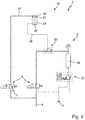
- Figure 2 schematically shows a circuit diagram of a filling element 1 according to a first embodiment.
- the filling element has a valve 2 with a working cylinder 20 accordingly Figure 1 on.
- Both chambers 23, 24 of the double-acting working cylinder 20 are each supplied with compressed air from a compressed air supply 4 via a 3/2-way valve 5.
- the compressed air supply 4 branches in parallel onto the two 3/2-way valves 5.
- One of the 3/2-way valves 5 leads via a connecting line 27 to the first chamber 23 of the working cylinder 20.
- the other of the two 3/2-way valves 5 leads via an OR valve 30 into a connecting line 28 to the second chamber 24 of the double-acting working cylinder 20th
- the OR valve 30 is designed in the form of a quick vent valve based on a normal OR valve, which is combined with a vent function for venting into the environment.
- the connecting line 28 is also connected to a pressure control device 3 via the OR valve 30.
- This has a buffer 32 and a proportional control valve 31.
- the pressure control device 3 is designed such that the actuating fluid can be removed from the working cylinder 20 in such a way that a switching speed, in the present case a closing speed, of the valve 2 can be individually controlled / regulated by setting a (counter) pressure by the pressure control device 3.
- the switching valves 5 are switched in such a way that compressed air, for example at a pressure of 6 bar, is fed to the second chamber 24 and the first chamber 23 is connected directly to the surroundings via an exhaust air 7, so that the air from the second chamber 23 can be drained essentially unthrottled.
- the piston 21 is located on the first side in the direction of the first chamber 23 and therefore the valve 2 is in a first switching position, which in the present case corresponds to an open position of the valve 2.
- the switching valves 5 are each brought into their other switching position, so that the first chamber 23 is then throttled with compressed air, for example again with a pressure of 6 bar , and the second chamber 24 is connected via the OR valve 30 of the pressure control device 3 to the buffer 32 and then in series therewith to the proportional control valve 31.
- the pressure in the supply line 28 and thus in the second chamber 24 is kept at a predetermined level, for example a pressure of 4 bar, via the proportional control valve 31.
- the buffer 32 serves to support the pressure control.
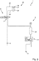
- FIG 3 a circuit diagram of a filling element 1 according to a second embodiment is shown schematically.
- the filling element 1 in turn has a valve 2 accordingly Figure 1 on.
- a 5/2-way valve 6 supplies both chambers 23, 24 of the double-acting working cylinder 20, wherein when the valve 2 is closed, the exhaust air from the second chamber 24 is in turn conveyed to a by means of a pressure control device 3, comprising a proportional control valve 31 and a buffer 32 , pressure-controlled duct is discharged.
- the closing speed becomes like too Figure 2 described by the back pressure set by means of the pressure control device 3 individually set and controlled / regulated, whereas the control and the exhaust air duct of the first chamber 23 and the loading of the chamber side 24 with compressed air to open the valve 2 are each not throttled via the 5/2-way valve 6 can be implemented.
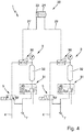
- FIG 4 schematically shows a circuit diagram of a filling element 1 according to a third embodiment.
- both the first chamber 23 and the second chamber 24 are each connected to their own pressure control device 3, as they are specifically with regard to Figure 2 for the second chamber 24 is described.
- an exhaust air duct of both chambers 23, 24 of the double-acting working cylinder 20 is made possible via a pressure-controlled exhaust air duct, each provided with a proportional control valve 31 of the respective pressure control device 3, each with a buffer 32, the control air for both chambers 23, 24 each over a 3/2-way valve 5 is supplied and the exhaust air is discharged via an OR valve 30 into a pressure-controlled channel provided via the respective pressure control device 3.
- this version allows individual control of the valve piston speed both on the opening side and on the closing side.
- the residual pressure when the pressure is discharged from the first chamber 23 and the residual pressure when the pressure is discharged from the second chamber 24 can be predetermined independently of one another. Therefore, the control effort is very low in this embodiment. However, individual opening and closing speeds can be provided.
- Figure 5 schematically shows a circuit diagram of a filling element 1 according to a fourth embodiment, in which the exhaust air duct of both chambers 23, 24 is also carried out via a separate pressure control device 3, but the pressurized air of both chambers 23, 24 is supplied via a common 5/2-way valve 6 and a common compressed air supply 4, which is connected to either the first chamber 23 or the second chamber 24, depending on the switching position of the 5/2-way valve.
- Figure 6 schematically shows a circuit diagram of a filling element 1 according to a fifth embodiment.
- the filling element 1 essentially has the structure of the filling element according to the first embodiment, as to Figure 1 describe on.
- the working cylinder 20 in the fifth embodiment is designed as a single-acting working cylinder 20, the first chamber 23 having a spring 8 and being actuated accordingly by spring force.
- the working cylinder 20 and accordingly the valve 2 are therefore designed to open compressed air and to close the spring force.
- the second chamber 24 After the second chamber 24 has been supplied with actuating fluid, the latter becomes after the 3/2-way valve 5 in the in Figure 6 Switching position shown was switched, correspondingly discharged via the pressure control device 3 from the second chamber 24 via the connecting line 28, the OR valve 30, the buffer 32 and the proportional control valve 31 to the exhaust air 7, again via the proportional control valve 31 the residual pressure in the chamber side 24 of the working cylinder 20 is set to a predetermined value.
- the value set by the proportional control valve 31 depends on a position of the piston 21 in the working cylinder 20. Since the spring force of the spring 8 on the piston 21 becomes weaker with increasing distance of the piston 21 from the first chamber 23, the residual pressure in of the second chamber 24 is regulated accordingly via the pressure control device 3, so that the piston 21 moves into the closed position at a substantially constant speed.
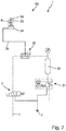
- Figure 7 schematically shows a circuit diagram of a filling element according to a sixth embodiment, which essentially corresponds to the fifth embodiment, but the working cylinder is designed to be spring-closing and compressed air-closing. Accordingly, in the sixth embodiment, an opening switching speed can be set individually via the pressure control device 3.
Landscapes
- Engineering & Computer Science (AREA)
- Mechanical Engineering (AREA)
- Filling Of Jars Or Cans And Processes For Cleaning And Sealing Jars (AREA)
- Basic Packing Technique (AREA)
- Fluid-Pressure Circuits (AREA)
- Filling Or Discharging Of Gas Storage Vessels (AREA)
Abstract
Description
- Die vorliegende Erfindung betrifft ein Füllorgan zum Abfüllen eines Füllprodukts in einen Behälter, bevorzugt zum Abfüllen von Soßen in Flaschen, sowie ein entsprechendes Verfahren.
- Es ist bekannt, zur Abfüllung von Füllprodukten, beispielsweise von Getränken oder fließfähigen Lebensmitteln wie beispielsweise Suppen oder Soßen, insbesondere Grillsoßen oder Ketchup, Rundlauffüller mit pneumatisch betätigten Füllorganen zu verwenden.
- Es ist bekannt, zum Öffnen und Schließen der Füllorgane einfach wirkende Pneumatikzylinder vorzusehen, welche etwa druckluftschließend und federkraftöffnend ausgebildet sind - oder auch umgekehrt. In solchen Füllorganen können unter anderem in den Zuleitungen zwischen einem Produkttank und den eigentlichen Füllventilen, welche beispielsweise als Absperrventile oder auch Membranventile mit fester Drosselbohrung im Ventilsitz ausgebildet sein können, Regelventile vorgesehen sein, die durch geeignetes Auf- und Zuschalten den Zuleitungsquerschnitt so verändern, dass ein anwendungsgerechtes Schnell- oder Langsamfüllen bei geöffnetem Füllventil möglich ist. Membranventile können ebenfalls eingesetzt werden, um bei Füllorganen mit einem Füllrohr-Auslauf durch Volumenarbeit, mithin partieller Vergrößerung des Füllrohrquerschnitts oder des Querschnitts in der Produktleitung vor dem Füllrohr durch Schalten zum Beispiel des Membranventils in die geeignete Richtung, Produktreste und Tropfen am Austritt des Füllrohrs zurückzuhalten, oder in das Füllrohr zurück zu saugen, was die Qualität der Abfüllung hinsichtlich des Vermeidens einer Verschmutzung der zu füllenden Behälter erhöht.
- Die Pneumatikzylinder werden üblicher Weise bei konstanten Arbeitsluftdrücken jeweils immer mit gleicher Geschwindigkeit geöffnet und geschlossen. Je nach den rheologischen Eigenschaften der abzufüllenden fließfähigen Füllprodukte kann ein langsames Schließen des Absperrorgans, etwa bei einem vorwärtsschließenden Ventil, und ein langsames Umschalten von Schnell- auf Langsamfüllung, etwa bei einem Membranventil in einer Produktleitung, bei niedrigviskosen Produkten vorteilhaft sein, um ein zu starkes Beschleunigen des Füllprodukts während des Schaltvorgangs zu vermeiden. Andererseits kann ein schnelles (Vorwärts-)Schließen bei hochviskosen Füllprodukten günstig sein, um ein Abreißen des Produktstrahls am Auslauf der Füllorgane zu optimieren. Zur anwendungsabhängigen Anpassung der Öffnungs- oder Schließgeschwindigkeit von Absperrventilen oder anderen über einen pneumatischen Arbeitszylinder angesteuerten Funktionseinheiten im Füllorgan werden deshalb in der Regel feste Zuluft- und/oder Abluftblenden in den Zuleitungen und Abluftführungen eingebaut, um die Zuluft bzw. die Abluft zu dem Arbeitszylinder derart zu drosseln, dass die Öffnungs- bzw. Schließgeschwindigkeit anwendungsfallspezifisch eingestellt werden kann. Damit wird eine für individuelle Anwendungsfälle hinreichende Ansteuerdynamik der pneumatischen Komponenten in den Füllorganen erreicht, z.B. für eine abzufüllende Produktgruppe mit annähernd identischen rheologischen Eigenschaften.
- Da die beschriebenen Füllorgane mit festen Zuluft- bzw. Abluftdrosseln zur Steuerung der Pneumatikzylinder ausgestattet sind, können bei Abfüllung eines Produktspektrums mit stark variierenden rheologischen Eigenschaften auf einer Füllmaschine, etwa Füllprodukte mit stark abweichenden Viskositäten, Füllprodukte mit und ohne feste Bestandteile und/oder Partikel, Newton'sche sowie nicht-Newton'sche Fluide, Fäden ziehende Füllprodukte, und/oder Füllprodukte mit rheologischer Fließgrenze einen erhöhten Umrüstaufwand zur jeweiligen Anpassung nach sich ziehen. Insbesondere müssen zum Umrüsten von einer Produktgruppe auf eine andere Produktgruppe die Zuluft- und/oder Abluftblenden getauscht werden.
- Bei niedrigviskosen Füllprodukten wirkt sich beispielsweise ein zu schnelles Schließen des Pneumatikzylinders zum Umschalten von Schnellfüllen auf Langsamfüllen und ein zu schnelles Schließen der Kegel der Absperrventile negativ aus. Durch den Schließimpuls wird das niederviskose Füllprodukt stark beschleunigt, wodurch es am Austritt des Absperrventils zum Oszillieren des Füllstrahls kommen kann. Da die vorwärts schließenden Ventilkegel der Absperrventile das Füllprodukt über die eigentliche Austrittsgeschwindigkeit des Füllstrahls hinaus beschleunigen, wird der Strahl gestaucht und verdickt sich oder gerät ebenfalls ins Oszillieren. Bei den häufig engen Mündungsquerschnitten der zu füllenden Behälter können diese Erscheinungen dazu führen, dass der Füllstrahl nicht mehr richtig in die Behältermündung treffen kann, Produktverlust, verschmutzte Behälteraußenseiten und Mündungen bzw. Gewinde, starkes Schäumen oder sogar Überschäumen aus den Behältern, sowie Produktspritzer aus den Behältern heraus sind mögliche Folgen.
- Bei hochviskosen Füllprodukten hingegen, die zum Anhaften oder Fädenziehen neigen oder eine rheologische Fließgrenze aufweisen, wirkt sich eine schnelle Schließgeschwindigkeit der Absperrventile positiv aus. Bei zu geringer Schließgeschwindigkeit hingegen kann es dazu kommen, dass beim Schließen Füllprodukt an den Ausläufen der Absperrventile haften bleibt, sich aufbaut, unkontrolliert abtropft und somit die zu füllenden Behälter an kritischen Stellen verschmutzt oder Fäden zieht, die ebenfalls die Behälter verschmutzen können. Füllprodukte mit rheologischer Fließgrenze müssen bei der Freistrahlabfüllung außerdem bei Füllende stark beschleunigt werden, um den Füllstrahl komplett in den Füllspiegel eintauchen zu lassen, da sich andererseits Produktkegel auf der Füllgut-Oberfläche bilden können, welche unter Umständen über die Behältermündung hinausragen und somit Behältermündung und Verschluss beschmutzen können.
- Beim Einsatz von mit einem pneumatischen Arbeitszylinder betätigten Funktionseinheiten, z.B. Membranventilen in Füllorganen mit Füllrohr-Auslauf zur Tropfenrückhaltung, kann durch zu schnelles Vergrößern des durch die Membranventile dargestellten Querschnitts und Volumens ferner das rückzuhaltende Füllprodukt zu schnell angesaugt werden, woraus sich die Gefahr des Einsaugens von Luft ergibt. Falls Luft eingesaugt wurde, kann das Füllrohr aber leerlaufen, wodurch ein negativer Effekt entsteht, insofern als dass Behälter überfüllt oder durch abtropfendes Produkt verschmutzt werden. Je nach rheologischen Eigenschaften der zu füllenden Medien in Kombination mit den Querschnitten des Füllrohrs ist die Anpassung der Schaltgeschwidigkeit der eingesetzten pneumatischen Funktionseinheiten sinnvoll.
- Für die Abfüllung eines breiten Produktspektrums ist eine Kompromiss-Auslegung von Zuluft- bzw. Abluftdrosseln für die Absperrventile der Füllorgane sowie der anderen eingesetzten pneumatischen Funktionseinheiten nur schwer zu realisieren. Meist resultiert daraus für die stark unterschiedlichen Füllprodukte eine signifikante Verschlechterung der Abfüllung für jedes der Produkte. Um ein weitgefächertes Produktspektrum optimal abfüllen zu können, ist bei der bestehenden Füllorgan- und Ansteuertechnik nur das zeit- und arbeitsintensive Austauschen von Zuluft- oder Abluftdrosseln möglich, um für Füllprodukte mit unterschiedlichen rheologischen Eigenschaften die jeweilige optimale Ansteuerdynamik der Ventile beziehungsweise pneumatischen Funktionseinheiten darzustellen.
- Ausgehend von dem bekannten Stand der Technik ist es eine Aufgabe der vorliegenden Erfindung, ein verbessertes Füllorgan zum Abfüllen eines Füllprodukts in einen Behälter, bevorzugt zum Abfüllen von Soßen in Flaschen, sowie ein entsprechendes Verfahren bereitzustellen.
- Die Aufgabe wird durch ein Füllorgan zum Abfüllen eines Füllprodukts in einen Behälter, bevorzugt zum Abfüllen von Soße in Flaschen mit den Merkmalen des Anspruchs 1 gelöst. Vorteilhafte Weiterbildungen ergeben sich aus den Unteransprüchen, der vorliegenden Beschreibung sowie den beigefügten Figuren.
- Entsprechend wird ein Füllorgan zum Abfüllen eines Füllprodukts in einen Behälter, bevorzugt zum Abfüllen von Soßen in Flaschen vorgeschlagen, umfassend ein Ventil zum Beeinflussen eines Füllproduktstroms, und einen über ein Betätigungsfluid schaltbaren Arbeitszylinder zum Vorgeben der Schaltstellungen des Ventils. Erfindungsgemäß ist eine Druckregelungsvorrichtung vorgesehen, über die das Betätigungsfluid aus dem Arbeitszylinder geregelt abführbar ist.
- Dadurch, dass das Betätigungsfluid über eine Druckregelungsvorrichtung geregelt aus dem Arbeitszylinder abführbar ist, können verschiedene Füllprodukte mit demselben Füllorgan abgefüllt werden, wobei die Füllprodukte stark abweichende rheologische Eigenschaften aufweisen können, etwa stark abweichende Viskositäten, Gehalt an festen Bestandteilen und/oder Partikeln, sowie Newton'sche und nicht-Newton'sche Fluide, Fäden ziehende Produkt und Produkte mit rheologischer Fließgrenze, ohne dabei mechanische Änderungen an dem Füllorgan vornehmen zu müssen beziehungsweise das Füllorgan umrüsten zu müssen, beispielsweise in Form von Auswechseln von Blenden oder einem Ventilkegel.
- Mit anderen Worten kann die Schaltgeschwindigkeit, mithin die Öffnungs- und Schließgeschwindigkeit, des Ventils ohne mechanische Eingriffe, beispielsweise einem Austausch von Abluftdrosseln, an die jeweiligen Produkteigenschaften angepasst beziehungsweise optimiert werden. Dadurch wird auf einer Füllmaschine ermöglicht, Füllprodukte verschiedenster rheologischer Eigenschaften über dasselbe Füllorgan mit auf das jeweilige Füllprodukt angepassten Parametern abzufüllen. Bevorzugt werden niedrigviskose Füllprodukte mit langsamer Schließgeschwindigkeit des Ventils und/oder hochviskose Füllprodukte mit schneller Schließgeschwindigkeit abgefüllt.
- Bevorzugt ist eine Schaltgeschwindigkeit, bevorzugt eine Öffnungsgeschwindigkeit und/oder eine Schließgeschwindigkeit, des Ventils durch die Druckregelungsvorrichtung individuell steuerbar/regelbar.
- Die Schaltgeschwindigkeit des Ventils kann mittels einer entsprechenden Gegendruckeinstellung in der Druckregelvorrichtung vorgegeben und entsprechend angepasst werden. Je höher die Einstellung des Gegendrucks in der Druckregelvorrichtung, desto langsamer ist die resultierende Schaltgeschwidigkeit.
- Unter Betätigungsfluid wird vorliegend ein Fluid verstanden, welches dem Arbeitszylinder zum Betätigen eines Kolbens des Arbeitszylinders auf zumindest einer Seite des Arbeitszylinders mit Bezug auf den Kolben, welcher den Innenraum des Arbeitszylinders in zwei Kammern unterteilt, zugeführt wird und welches dadurch auf den Kolben wirkt. Bevorzugt ist das Arbeitsfluid gasförmig, besonders bevorzugt ein Gas, ein Gasgemisch, Druckluft, oder flüssig, besonders bevorzugt eine Hydraulikflüssigkeit, bevorzugt ein Hydrauliköl.
- In einer bevorzugten weiteren Ausführungsform ist der Druck in der Druckregelvorrichtung in Bezug auf die Schaltstellung beziehungsweise in Bezug auf eine Position eines Kolbens des Arbeitszylinders veränderbar, mithin anpassbar beziehungsweise einstellbar. So kann die Schaltgeschwindigkeit entlang des Wegs des Kolbens in dem Arbeitszylinder eingestellt werden. Insbesondere, wenn der Arbeitszylinder einfachwirkend ausgebildet ist und die der Druckluftseite gegenüberliegende Kammer des Arbeitszylinders federbeaufschlagt ist, kann durch eine Änderung des Drucks auf der Druckseite durch die Druckregelungsvorrichtung auf eine auf den Kolben wirkende Federkraft, welche sich mit zunehmendem Weg des Kolbens in dem Arbeitszylinder entsprechend der geringer werdenden Stauchung der Feder verringert, ausgeglichen werden.
- Gemäß einer weiteren bevorzugten Ausführungsform erfolgt eine Zufuhr von zu dem Arbeitszylinder zugeführten Betätigungsfluid ungedrosselt. Dadurch erfolgt eine Geschwindigkeitssteuerung und/oder -regelung einzig über die Druckregelungsvorrichtung bei der Abfuhr von Betätigungsfluid. Ein derart ausgebildetes Füllorgan weist entsprechend einen einfachen und gleichzeitig robusten Aufbau auf.
- Eine Regelung des Drucks kann besonders präzise erfolgen, wenn die Druckregelungsvorrichtung gemäß einer weiteren bevorzugten Ausführungsform ein Regelventil, bevorzugt ein Proportional-Regelventil, aufweist.
- Um die Druckregelung durch die Druckregelungsvorrichtung zu unterstützen, kann die Druckregelungsvorrichtung einen Pufferspeicher zum Puffern von Betätigungsfluid aufweisen, wobei der Pufferspeicher bevorzugt zwischen dem Arbeitszylinder und dem Regelventil angeordnet ist.
- In einer weiteren bevorzugen Ausführungsform kann die Druckregelungsvorrichtung ein Oder-Ventil beziehungsweise ein Wechselventil aufweisen. Dadurch ist es möglich, zuströmendes Betätigungsfluid beim Druckbeaufschlagen des Arbeitszylinders an denjenigen Teilen der Druckregelungsvorrichtung vorbeizuführen, welche den Residualdruck des Betätigungsfluids beim Abführen des Betätigungsfluids regeln. Damit kann zum Zuführen des Betätigungsfluids ein eigener Kanal bereitgestellt werden. Zum Abführen des Betätigungsfluids kann ein weiterer Kanal bereitgestellt werden, über welchen der Residualdruck beim Abführen regelbar ist. Die beiden Kanäle können dabei durch das Oder-Ventil abwechselnd mit dem Arbeitszylinder beziehungsweise einer Verbindungsleitung zu einer Seite des Arbeitszylinders verbunden werden.Gemäß einer besonders bevorzugten Ausführungsform ist der Arbeitszylinder als Pneumatikzylinder ausgebildet, wobei das Betätigungsfluid bevorzugt Druckluft ist. Dadurch kann das Füllorgan in gängigen Abfüllanlagen eingesetzt werden, welche in der Regel mit Druckluft betrieben werden, ohne dass große Änderungen an der Abfüllanlage notwendig sind.
- Ein besonders einfacher Aufbau des Füllorgans kann erzielt werden, wenn der Arbeitszylinder gemäß einer weiteren bevorzugten Ausführungsform ein einfachwirkender Arbeitszylinder, bevorzugt ein einfachwirkender Pneumatikzylinder, ist. Bevorzugt ist der Arbeitszylinder druckluftschließend und federkraftöffnend oder druckluftöffnend und federkraftschließend ausgebildet.
- Wenn der Arbeitszylinder als doppeltwirkender Arbeitszylinder, bevorzugt als doppeltwirkender Pneumatikzylinder, ausgebildet ist, ist es möglich, die Druckregelungsvorrichtung auf beide Kammern des Arbeitszylinders Einfluss ausüben zu lassen. Mit andern Worten kann mindestens eine Druckregelungsvorrichtung derart mit dem Arbeitszylinder verschaltet werden, dass eine Druckregelungsvorrichtung jeweils dann mit einer der beiden Kammern des Zylinders verbunden ist, wenn aus dieser Betätigungsfluid, bevorzugt Druckluft, abgeführt werden soll beziehungsweise wird. Dadurch kann beidseitig alternierend eine Abluft-Druckluftregelung erfolgen, so dass die Schaltgeschwindigkeit in beide Schaltrichtungen individuell einstellbar ist. Der bereitgestellte Gegendruck kann für beide Schaltrichtungen unterschiedlich sein, was in unterschiedlichen Schaltgeschwindigkeiten resultiert. In die jeweils andere Kammer, welche alternierend entsprechend nicht mit einer Druckregelungsvorrichtung verbunden ist und auf welcher dem Arbeitszylinder entsprechend unter Druck, welcher höher ist als der durch die Druckregelungsvorrichtung vorgegebene Druck, stehendes Betätigungsfluid zugeführt wird, kann die Zufuhr jeweils ungedrosselt erfolgen. Es müssen folglich auch auf der Zufuhrseite keine Drosselblenden vorgesehen werden.
- Ein besonders robustes und einfach zu verschaltendes Füllorgan kann realisiert werden, indem der doppeltwirkende Arbeitszylinder zwei Anschlüsse aufweist, wobei jeder der Anschlüsse mit einer separaten, eine Druckregelungsvorrichtung aufweisenden Ablaufführung verbindbar ist, oder die beiden Anschlüsse, bevorzugt über ein Ventil, besonders bevorzugt ein 5-2-Wege-Schaltventil, abwechselnd mit einer gemeinsamen, die Druckregelungsvorrichtung aufweisenden Ablaufführung verbindbar sind.
- Gemäß einer weiteren bevorzugten Ausführungsform ist das Ventil als Füllventil zur Bereitstellung und zum Unterbrechen eines Füllproduktstroms aus dem Füllorgan ausgebildet. Dadurch kann ein Füllprodukt aus dem Füllorgan an einen zu befüllenden Behälter bereitgestellt, gesteuert/geregelt und unterbrochen werden.
- Gemäß einer weiteren bevorzugten Ausführungsform ist das Ventil als Membranventil oder Drosselventil zum Einstellen eines Durchlassquerschnitts einer Füllproduktleitung des Füllorgans ausgebildet. Dadurch kann ein Volumenstrom von Füllprodukt im Füllorgan gesteuert/geregelt werden.
- In einer weiteren bevorzugten Ausführungsform wird der durch die Druckregelungsvorrichtung eingestellte Residualdruck bezogen auf die Position des Kolbens im Arbeitszylinder entlang dessen Längsachse verändert, so dass beispielsweise nahe der End-Schaltstellungen der Differenzdruck zwischen der Druckzufuhrseite und der Seite, aus welcher Betätigungsfluid über die Druckregelungsvorrichtung abgeführt wird, gering ist, und zwischen diesen Endlagen ein höherer Druckunterschied eingestellt wird und sich der Kolben entsprechend schneller bewegt. Auf diese Weise kann beispielsweise auch eine Art "Anschlagsdämpfung" für die Endlagen bereitgestellt werden.
- Die oben gestellte Aufgabe wird weiterhin durch ein Verfahren zum Steuern/Regeln eines Füllorgans zum Abfüllen eines Füllprodukts in einen Behälter mit den Merkmalen des Anspruchs 11 gelöst. Vorteilhafte Weiterbildungen des Verfahrens ergeben sich aus der vorliegenden Beschreibung, den Unteransprüchen und den Figuren.
- Entsprechend wird ein Verfahren zum Steuern/Regeln eines Füllorgans zum Abfüllen eines Füllprodukts in einen Behälter vorgeschlagen, umfassend die Schritte des Beaufschlagens einer ersten Kammer eines Arbeitszylinders eines Ventils des Füllorgans mit einem Betätigungsfluid zum Erreichen einer ersten Schaltstellung des Ventils, und des Abführens des Betätigungsfluids über eine Druckregelungsvorrichtung zum Erreichen einer zweiten Schaltstellung des Ventils.
- Bevorzugt kann eine Schaltgeschwindigkeit des Ventils durch eine Einstellung eines Drucks durch die Druckregelungsvorrichtung individuell gesteuert/geregelt werden.
- Durch das Verfahren werden die hinsichtlich des Füllorgans beschriebenen Vorteile und Wirkungen analog erzielt.
- Bevorzugte weitere Ausführungsformen der Erfindung werden durch die nachfolgende Beschreibung der Figuren näher erläutert. Dabei zeigen:
- Figur 1
- schematisch ein Ventil mitsamt Arbeitszylinder eines Füllorgans;
- Figur 2
- schematisch einen Schaltplan eines Füllorgans gemäß einer ersten Ausführungsform;
- Figur 3
- schematisch einen Schaltplan eines Füllorgans gemäß einer zweiten Ausführungsform;
- Figur 4
- schematisch einen Schaltplan eines Füllorgans gemäß einer dritten Ausführungsform;
- Figur 5
- schematisch einen Schaltplan eines Füllorgans gemäß einer vierten Ausführungsform;
- Figur 6
- schematisch einen Schaltplan eines Füllorgans gemäß einer fünften Ausführungsform; und
- Figur 7
- schematisch einen Schaltplan eines Füllorgans gemäß einer sechsten Ausführungsform.
- Im Folgenden werden bevorzugte Ausführungsbeispiele anhand der Figuren beschrieben. Dabei werden gleiche, ähnliche oder gleichwirkende Elemente in den unterschiedlichen Figuren mit identischen Bezugszeichen versehen, und auf eine wiederholte Beschreibung dieser Elemente wird teilweise verzichtet, um Redundanzen zu vermeiden.
- In
Figur 1 ist schematisch ein Füllorgan 1 zum Abfüllen eines Füllprodukts in einen Behälter mit einem Ventil 2 zum Beeinflussen eines Füllproduktstroms des in den Behälter fließenden Füllprodukts, bevorzugt zum Abfüllen von Soße in Flaschen, gezeigt. - Das Füllorgan 1 weist einen Arbeitszylinder 20 auf, mittels dessen das Ventil 2 geschaltet werden kann. Der Arbeitszylinder 20 ist über ein Betätigungsfluid, vorliegend in Form von Druckluft, schaltbar. Hierzu weist der Arbeitszylinder 20 einen Kolben 21 auf, welcher einen Innenraum des Arbeitszylinders 20 in eine erste Kammer 23 und in eine zweite Kammer 24 unterteilt. Der Arbeitszylinder 20 ist vorliegend als doppeltwirkender Pneumatikzylinder ausgebildet. Alternativ kann der Arbeitszylinder 20 auch einfachwirkend und/oder als einfachwirkender oder doppeltwirkender Hydraulikzylinder ausgebildet sein.
- Das Ventil 2 ist vorliegend als Absperr-Freistrahlventil ausgeführt. Alternativ kann das Ventil 2 auch eine andere Form aufweisen und beispielsweise als Membranventil oder Drosselventil zur Variation des Füllproduktstroms ausgebildet sein.
- Die Schaltstellungen des Ventils 2 sind über die Schaltstellung des Arbeitszylinders 20 vorgebbar. Hierzu ist der Kolben 21 über eine Kolbenstange 22 mit einem Ventilkegel 25 des Ventils 2 verbunden, welcher in Längsrichtung des Ventils 2 über die Bewegung des Kolbens 21 beweglich ist. In einer geschlossenen Schaltstellung des Ventils 2 ist der Ventilkegel 25 in Kontakt mit einem Ventilsitz 26. Zum Öffnen wird der Ventilkegel 25 durch eine Bewegung des Kolbens 21 aus dem Ventilsitz 26 heraus gehoben, so dass ein entsprechender Durchlassquerschnitt beziehungsweise Ringspalt zwischen Ventilkegel 25 und Ventilsitz 26 entsteht, durch welchen hindurch das Füllprodukt strömen kann. Durch das Absenken des Ventilkegels 25 in den Ventilsitz 26 hinein und durch das Anheben aus diesem heraus kann entsprechend der Füllproduktstrom gesteuert werden.
-
Figur 2 zeigt schematisch einen Schaltplan eines Füllorgans 1 gemäß einer ersten Ausführungsform. Das Füllorgan weist ein Ventil 2 mit einem Arbeitszylinder 20 entsprechendFigur 1 auf. - Beide Kammern 23, 24 des doppeltwirkenden Arbeitszylinders 20 werden jeweils über ein 3/2-Wegeventil 5 mit Druckluft aus einer Druckluftversorgung 4 versorgt. Hierzu zweigt sich die Druckluftversorgung 4 parallel auf die beiden 3/2-Wegeventile 5 auf. Eines der 3/2-Wegeventile 5 führt dabei über eine Verbindungsleitung 27 zur ersten Kammer 23 des Arbeitszylinders 20. Das andere der beiden 3/2-Wegeventile 5 führt über ein Oder-Ventil 30 in eine Verbindungsleitung 28 zur zweiten Kammer 24 des doppeltwirkenden Arbeitszylinders 20.
- Das Oder-Ventil 30 ist vorliegend in Form eines Schnellentlüftungsventils auf Basis eines normalen Oder-Ventils ausgebildet, , das mit einer Entlüftungsfunktion zur Entlüftung in die Umgebung kombiniert ist.
- Über das Oder-Ventil 30 ist die Verbindungsleitung 28 ferner mit einer Druckregelungsvorrichtung 3 verbunden. Diese weist einen Puffer 32 und ein Proportional-Regelventil 31 auf. Die Druckregelungsvorrichtung 3 ist so ausgebildet, dass das Betätigungsfluid aus dem Arbeitszylinder 20 abführbar ist, derart, dass eine Schaltgeschwindigkeit, vorliegend eine Schließgeschwindigkeit, des Ventils 2 durch eine Einstellung eines (Gegen-) Drucks durch die Druckregelungsvorrichtung 3 individuell steuerbar/regelbar ist.
- In
Figur 2 gezeigt sind die Schaltventile 5 derart geschaltet, dass der zweiten Kammer 24 Druckluft, beispielsweise mit einem Druck von 6 bar, zugeführt wird und die erste Kammer 23 über eine Abluft 7 direkt mit der Umgebung verbunden ist, so dass die Luft aus der zweiten Kammer 23 mithin im Wesentlichen ungedrosselt abgelassen werden kann. Der Kolben 21 liegt auf der ersten Seite in Richtung der ersten Kammer 23 und daher steht das Ventil 2 in einer ersten Schaltstellung, welche vorliegend einer geöffneten Stellung des Ventils 2 entspricht. - Um den Arbeitszylinder 20 und damit auch das Ventil 2 in die andere Schaltstellung zu bringen, werden die Schaltventile 5 jeweils in deren andere Schaltstellung gebracht, so dass dann die erste Kammer 23 ungedrosselt mit Druckluft, beispielsweise wiederum mit einem Druck von 6 bar, versorgt wird, und die zweite Kammer 24 über das Oder-Ventil 30 der Druckregelvorrichtung 3 mit dem Puffer 32 und seriell daran anschließend mit dem Proportional-Regelventil 31 verbunden ist.
- Der Druck in der Versorgungsleitung 28 und damit in der zweiten Kammer 24 wird über das Proportionalregelventil 31 auf einem vorgegebenen Niveau, beispielsweise einem Druck von 4 bar, gehalten. Der Puffer 32 dient zur Unterstützung der Druckregelung.
- Die Steuerung der Schaltgeschwindigkeit, mit welcher sich der Kolben 21 und damit der Ventilkegel 25 bewegt, findet durch Einstellen des Residualdrucks beziehungsweise des verbleibenden Gegendrucks in der zweiten Kammer 24 durch die Druckregelungsvorrichtung 3 statt, wobei der ersten Kammer 23, welche in dieser Schaltstellung als Schließhubseite wirkt, Druckluft ungedrosselt über das eine 3/2-Wegeventil 5 zugeführt wird.
- Die Abluft aus der zweiten Kammer 24, welche demgemäß der Öffnungshubseite des doppeltwirkenden Arbeitszylinders 20 entspricht, wird folglich in den druckgeregelten Gegendruckkanal über die Druckregelungsvorrichtung 3 abgeführt. Je höher der durch die Druckregelungsvorrichtung 3 eingestellte Gegendruck und folglich je geringer die Druckdifferenz zwischen der ersten Kammer 23 und der zweiten Kamer 24, desto geringer ist die Schaltgeschwindigkeit, hier die Schließgeschwindigkeit, des Arbeitszylinders 20, und damit auch die Schließgeschwindigkeit des Ventils 2.
- Um den Arbeitszylinder 20 und somit das Ventil 2 wieder in die in
Figur 2 gezeigte Schaltstellung zurück zu bewegen, müssen die 3/2-Wegeventile 5 jeweils entsprechend wieder zurück in die inFigur 2 gezeigte Stellung bewegt werden. Die Bewegung des Kolbens 21 erfolgt dann ungeregelt, da die Verbindungsleitung 27 direkt mit der Abluft 7 verbunden ist und die Verbindungsleitung 28 direkt mit der Druckluftzufuhr 4 verbunden ist. Damit wird hier die Bewegung des Arbeitszylinders mit einer höheren Geschwindigkeit stattfinden, als bei der entgegengesetzten Bewegung, bei der der Kolben gegen den Gegendruck bzw. Residualdruck bewegt wird. - In
Figur 3 ist schematisch ein Schaltplan eines Füllorgans 1 gemäß einer zweiten Ausführungsform gezeigt. Das Füllorgan 1 weist wiederum ein Ventil 2 entsprechendFigur 1 auf. - In dieser zweiten Ausführungsform versorgt ein 5/2-Wegeventil 6 beide Kammern 23, 24 des doppeltwirkenden Arbeitszylinders 20, wobei beim Schließen des Ventils 2 die Abluft der zweiten Kammer 24 wiederum in einen mittels einer Druckregelungsvorrichtung 3, umfassend ein Proportionalregelventil 31 und einen Puffer 32, druckgeregelten Kanal abgeführt wird. Die Schließgeschwindigkeit wird wie zu
Figur 2 beschrieben durch den mittels der Druckregelungsvorrichtung 3 eingestellten Gegendruck individuell eingestellt und gesteuert/geregelt, wohingegen das Ansteuern und die Abluftführung der ersten Kammer 23 sowie das Beaufschlagen der Kammer Seite 24 mit Druckluft zum Öffnen des Ventils 2 jeweils nicht gedrosselt über das 5/2-Wegeventil 6 umgesetzt werden. -
Figur 4 zeigt schematisch einen Schaltplan eines Füllorgans 1 gemäß einer dritten Ausführungsform. Hier sind sowohl die erste Kammer 23 als auch die zweite Kammer 24 jeweils mit einer eigenen Druckregelungsvorrichtung 3 verbunden, wie sie konkret in Hinblick aufFigur 2 für die zweite Kammer 24 beschrieben ist. - Bei dieser dritten Ausführungsform wird eine Abluftführung beider Kammern 23, 24 des doppeltwirkenden Arbeitszylinders 20 über je einen über je ein Proportionalregelventil 31 der jeweiligen Druckregelungsvorrichtung 3 bereitgestellten druckgeregelten Abluftkanal mit je einem Puffer 32 ermöglicht, wobei die Steuerluft für beide Kammern 23, 24 jeweils über je ein 3/2-Wegeventil 5 zugeführt und die Abluft über je ein Oder-Ventil 30 in je einen über die jeweilige Druckregelungsvorrichtung 3 bereitgestellten druckgeregelten Kanal abgeführt wird. Diese Ausführung erlaubt in Abhängigkeit der für jeden Rückluftkanal eingestellten Gegendrücke sowohl öffnungsseitig als auch schließseitig eine individuelle Regelung der Ventilkolbengeschwindigkeit.
- Da zwei Druckregelungsvorrichtungen 3 vorgesehen sind, können der Residualdruck beim Abführen des Drucks aus der ersten Kammer 23 und der Residualdruck beim Abführen des Drucks aus der zweiten Kammer 24 unabhängig voneinander vorgegeben werden. Mithin ist bei dieser Ausführungsform der Steuerungs-/Regelungsaufwand sehr gering. Es können dennoch individuelle Öffnungs- und Schließgeschwindigkeiten vorgesehen werden.
-
Figur 5 zeigt schematisch einen Schaltplan eines Füllorgans 1 gemäß einer vierten Ausführungsform, bei welcher ebenfalls die Abluftführung beider Kammern 23, 24 über je eine separate Druckregelungsvorrichtung 3 erfolgt, wobei jedoch die Beaufschlagung mit Druckluft beider Kammern 23, 24 über ein gemeinsames 5/2-Wegeventil 6 und eine gemeinsame Druckluftzufuhr 4, welche entsprechend je nach Schaltstellung des 5/2-Wegeventils entweder mit der ersten Kammer 23 oder der zweiten Kammer 24 verbunden ist, stattfindet. -
Figur 6 zeigt schematisch einen Schaltplan eines Füllorgans 1 gemäß einer fünften Ausführungsform. Das Füllorgan 1 weist im Wesentlichen den Aufbau des Füllorgans gemäß der ersten Ausführungsform, wie zuFigur 1 beschreiben, auf. - Im Gegensatz zur ersten Ausführungsform ist der Arbeitszylinder 20 bei der fünften Ausführungsform als einfachwirkender Arbeitszylinder 20 ausgebildet, wobei die erste Kammer 23 eine Feder 8 aufweist und entsprechend federkraftbetätigt ist. Der Arbeitszylinder 20 und entsprechend das Ventil 2 sind mithin druckluftöffnend und federkraftschließend ausgebildet. Nach dem Beaufschlagen der zweiten Kammer 24 mit Betätigungsfluid wird letzteres, nachdem das 3/2-Wegeventil 5 in die in
Figur 6 gezeigt Schaltstellung geschaltet wurde, entsprechend wiederum über die Druckregelungsvorrichtung 3 aus der zweiten Kammer 24 über die Verbindungsleitung 28, dem Oder-Ventil 30, dem Puffer 32 und dem Proportional-Regelventil 31 an die Abluft 7 abgeführt, wobei wiederum über das Proportional-Regelventil 31 der Residualdruck in der Kammer Seite 24 des Arbeitszylinders 20 auf einen vorbestimmten Wert eingestellt wird. - Vorliegend ist der durch das Proportional-Regelventil 31 eingestellte Wert abhängig von einer Position des Kolbens 21 im Arbeitszylinder 20. Da die Federkraft der Feder 8 auf den Kolben 21 mit zunehmenden Abstand des Kolbens 21 von der ersten Kammer 23 schwächer wird, wird der Residualdruck in der zweiten Kammer 24 über die Druckregelungsvorrichtung 3 entsprechend herabgeregelt, so dass der Kolben 21 sich mit im Wesentlichen konstanter Geschwindigkeit in die Schließstellung bewegt.
-
Figur 7 zeigt schematisch einen Schaltplan eines Füllorgans gemäß einer sechsten Ausführungsform, welche im Wesentlichen der fünften Ausführungsform entspricht, der Arbeitszylinder jedoch federkraftschließend und druckluftschließend ausgebildet ist. Entsprechend kann bei der sechsten Ausführungsform eine Öffnungsschaltgeschwindigkeit über die Druckregelungsvorrichtung 3 individuell eingestellt werden. - Soweit anwendbar, können alle einzelnen Merkmale, die in den Ausführungsbeispielen dargestellt sind, miteinander kombiniert und/oder ausgetauscht werden, ohne den Bereich der Erfindung zu verlassen.
-
- 1
- Füllorgan
- 2
- Ventil
- 20
- Arbeitszylinder
- 21
- Kolben
- 22
- Kolbenstange
- 23
- Erste Kammer
- 24
- Zweite Kammer
- 25
- Ventilkegel
- 26
- Ventilsitz
- 27
- Verbindungsleitung
- 28
- Verbindungsleitung
- 3
- Druckregelungsvorrichtung
- 30
- Oder-Ventil
- 31
- Proportional-Regelventil
- 32
- Puffer
- 4
- Druckluftzufuhr
- 5
- 3/2-Wegeventil
- 6
- 5/2-Wegeventil
- 7
- Abluftleitung
- 8
- Feder
Claims (12)
- Füllorgan (1) zum Abfüllen eines Füllprodukts in einen Behälter, bevorzugt zum Abfüllen von Soßen in Flaschen, umfassend ein Ventil (2) zum Beeinflussen eines Füllproduktstroms, und einen über ein Betätigungsfluid schaltbaren Arbeitszylinder (20) zum Vorgeben der Schaltstellungen des Ventils (2),
dadurch gekennzeichnet, dass
eine Druckregelungsvorrichtung (3) vorgesehen ist, über die das Betätigungsfluid aus dem Arbeitszylinder (20) geregelt abführbar ist. - Füllorgan (1) gemäß Anspruch 1, dadurch gekennzeichnet, dass eine Schaltgeschwindigkeit, bevorzugt eine Öffnungsgeschwindigkeit und/oder eine Schließgeschwindigkeit, des Ventils (2) durch die Druckregelungsvorrichtung (3) individuell steuerbar/regelbar ist.
- Füllorgan (1) gemäß Anspruch 1 oder 2, dadurch gekennzeichnet, dass eine Zufuhr von zu dem Arbeitszylinder (20) zugeführten Betätigungsfluid ungedrosselt erfolgt.
- Füllorgan (1) gemäß einem der vorstehenden Ansprüche, dadurch gekennzeichnet, dass die Druckregelungsvorrichtung (3) ein Regelventil, bevorzugt ein Proportional-Regelventil (31), aufweist.
- Füllorgan (1) gemäß einem der vorstehenden Ansprüche, dadurch gekennzeichnet, dass die Druckregelungsvorrichtung (3) einen Pufferspeicher (32) zum Puffern von Betätigungsfluid aufweist, wobei der Pufferspeicher (32) bevorzugt zwischen dem Arbeitszylinder (20) und dem Regelventil angeordnet ist.
- Füllorgan (1) gemäß einem der vorstehenden Ansprüche, dadurch gekennzeichnet, dass der Arbeitszylinder (20) als Pneumatikzylinder ausgebildet ist, wobei das Betätigungsfluid bevorzugt Druckluft ist.
- Füllorgan (1) gemäß einem der vorstehenden Ansprüche, dadurch gekennzeichnet, dass der Arbeitszylinder (20) ein einfachwirkender Arbeitszylinder (20), bevorzugt ein einfachwirkender Pneumatikzylinder, ist.
- Füllorgan (1) gemäß einem der vorstehenden Ansprüche, dadurch gekennzeichnet, dass der Arbeitszylinder (20) ein doppeltwirkender Arbeitszylinder (20), bevorzugt ein doppeltwirkender Pneumatikzylinder, ist.
- Füllorgan (1) gemäß Anspruch 8, dadurch gekennzeichnet, dass der doppeltwirkende Arbeitszylinder (20) zwei Anschlüsse aufweist, wobei jeder der Anschlüsse mit einer separaten, eine Druckregelungsvorrichtung (3) aufweisenden Ablaufführung verbindbar ist, oder die beiden Anschlüsse, bevorzugt über ein Ventil, besonders bevorzugt ein 5-2-Wege-Schaltventil (6), abwechselnd mit einer gemeinsamen, die Druckregelungsvorrichtung (3) aufweisenden Ablaufführung verbindbar sind.
- Füllorgan (1) gemäß einem der vorstehenden Ansprüche, dadurch gekennzeichnet, dass das Ventil (2) als Füllventil zum Bereitstellen und Unterbrechen eines Füllproduktstroms aus dem Füllorgan (1) ausgebildet ist, oder dass das Ventil (2) als Membranventil oder Drosselventil zum Einstellen eines Durchlassquerschnitts einer Füllproduktleitung des Füllorgans (1) ausgebildet ist.
- Verfahren zum Steuern/Regeln eines Füllorgans (1) zum Abfüllen eines Füllprodukts in einen Behälter, umfassend die folgenden Schritte:- Beaufschlagen einer ersten Kammer (23) eines Arbeitszylinders (20) eines Ventils (2) des Füllorgans (1) mit einem Betätigungsfluid zum Erreichen einer ersten Schaltstellung des Ventils (2); und- Abführen des Betätigungsfluids über eine Druckregelungsvorrichtung (3) zum Erreichen einer zweiten Schaltstellung des Ventils (2).
- Verfahren gemäß Anspruch 11, dadurch gekennzeichnet, dass eine Schaltgeschwindigkeit des Ventils (2) durch eine Einstellung eines Drucks durch die Druckregelungsvorrichtung (3) individuell gesteuert/geregelt wird.
Priority Applications (1)
| Application Number | Priority Date | Filing Date | Title |
|---|---|---|---|
| SI201930058T SI3587341T1 (sl) | 2018-06-28 | 2019-06-28 | Polnilni organ in postopek za polnjenje polnilnega izdelka v vsebnik |
Applications Claiming Priority (1)
| Application Number | Priority Date | Filing Date | Title |
|---|---|---|---|
| DE102018115608.1A DE102018115608A1 (de) | 2018-06-28 | 2018-06-28 | Füllorgan und Verfahren zum Abfüllen eines Füllprodukts in einen Behälter |
Publications (2)
| Publication Number | Publication Date |
|---|---|
| EP3587341A1 true EP3587341A1 (de) | 2020-01-01 |
| EP3587341B1 EP3587341B1 (de) | 2021-04-14 |
Family
ID=67137631
Family Applications (1)
| Application Number | Title | Priority Date | Filing Date |
|---|---|---|---|
| EP19183234.4A Active EP3587341B1 (de) | 2018-06-28 | 2019-06-28 | Füllorgan und verfahren zum abfüllen eines füllprodukts in einen behälter |
Country Status (5)
| Country | Link |
|---|---|
| EP (1) | EP3587341B1 (de) |
| JP (1) | JP7365149B2 (de) |
| CN (1) | CN110655025B (de) |
| DE (1) | DE102018115608A1 (de) |
| SI (1) | SI3587341T1 (de) |
Cited By (1)
| Publication number | Priority date | Publication date | Assignee | Title |
|---|---|---|---|---|
| WO2022234472A1 (en) * | 2021-05-04 | 2022-11-10 | Filkraft Pty Ltd | Rotary piston filler arrangement |
Families Citing this family (1)
| Publication number | Priority date | Publication date | Assignee | Title |
|---|---|---|---|---|
| DE102024110890A1 (de) * | 2024-04-18 | 2025-10-23 | Krones Aktiengesellschaft | Vorrichtung zum Befüllen eines Behälters mit einem Füllprodukt |
Citations (5)
| Publication number | Priority date | Publication date | Assignee | Title |
|---|---|---|---|---|
| US5137187A (en) * | 1991-02-20 | 1992-08-11 | H.G. Kalish | Anti-spray fluid dispensing nozzle |
| US5287997A (en) * | 1992-10-13 | 1994-02-22 | Tetra Laval Holdings & Finance Sa | Carton filling system |
| JPH1059491A (ja) * | 1996-08-23 | 1998-03-03 | Shibuya Kogyo Co Ltd | 充填装置 |
| FR2791033A1 (fr) * | 1999-03-17 | 2000-09-22 | Pierre Guillon | Systeme de remplissage de recipients |
| DE102014117831A1 (de) * | 2014-12-04 | 2016-06-09 | Krones Ag | Vorrichtung zum Befüllen eines Behälters mit einem Füllprodukt |
Family Cites Families (5)
| Publication number | Priority date | Publication date | Assignee | Title |
|---|---|---|---|---|
| JPH0577891A (ja) * | 1991-09-11 | 1993-03-30 | Japan Tobacco Inc | 液体充填機の液だれ防止機構 |
| JPH06286703A (ja) * | 1993-03-29 | 1994-10-11 | Osaka Kiko Co Ltd | 液体充填装置 |
| JP4250450B2 (ja) * | 2002-05-10 | 2009-04-08 | 日清フーズ株式会社 | 充填包装装置および充填包装方法 |
| DE102010007152B4 (de) * | 2010-02-05 | 2017-03-30 | Hoerbiger Automatisierungstechnik Holding Gmbh | Fluidbetätigter Stellantrieb an einer Armatur |
| CN202302200U (zh) * | 2011-08-15 | 2012-07-04 | 博思特能源装备(天津)股份有限公司 | 用于燃气压力控制系统的电动/气动控制器 |
-
2018
- 2018-06-28 DE DE102018115608.1A patent/DE102018115608A1/de not_active Withdrawn
-
2019
- 2019-06-21 JP JP2019115424A patent/JP7365149B2/ja active Active
- 2019-06-27 CN CN201910568027.3A patent/CN110655025B/zh active Active
- 2019-06-28 EP EP19183234.4A patent/EP3587341B1/de active Active
- 2019-06-28 SI SI201930058T patent/SI3587341T1/sl unknown
Patent Citations (5)
| Publication number | Priority date | Publication date | Assignee | Title |
|---|---|---|---|---|
| US5137187A (en) * | 1991-02-20 | 1992-08-11 | H.G. Kalish | Anti-spray fluid dispensing nozzle |
| US5287997A (en) * | 1992-10-13 | 1994-02-22 | Tetra Laval Holdings & Finance Sa | Carton filling system |
| JPH1059491A (ja) * | 1996-08-23 | 1998-03-03 | Shibuya Kogyo Co Ltd | 充填装置 |
| FR2791033A1 (fr) * | 1999-03-17 | 2000-09-22 | Pierre Guillon | Systeme de remplissage de recipients |
| DE102014117831A1 (de) * | 2014-12-04 | 2016-06-09 | Krones Ag | Vorrichtung zum Befüllen eines Behälters mit einem Füllprodukt |
Cited By (1)
| Publication number | Priority date | Publication date | Assignee | Title |
|---|---|---|---|---|
| WO2022234472A1 (en) * | 2021-05-04 | 2022-11-10 | Filkraft Pty Ltd | Rotary piston filler arrangement |
Also Published As
| Publication number | Publication date |
|---|---|
| JP2020023356A (ja) | 2020-02-13 |
| CN110655025B (zh) | 2021-09-24 |
| DE102018115608A1 (de) | 2020-01-02 |
| EP3587341B1 (de) | 2021-04-14 |
| SI3587341T1 (sl) | 2021-08-31 |
| CN110655025A (zh) | 2020-01-07 |
| JP7365149B2 (ja) | 2023-10-19 |
Similar Documents
| Publication | Publication Date | Title |
|---|---|---|
| DE69715936T2 (de) | Heissklebstoff-Auftragvorrichtung und Düse dafür | |
| DE3730837C2 (de) | Entlüftungseinrichtung zur Verwendung in einer Gießmaschine | |
| EP3031774B1 (de) | Füllventil zum befüllen eines behälters mit einem füllprodukt | |
| EP3902635B1 (de) | Jet-dosierventil | |
| EP3078628B1 (de) | Vorrichtung zum variieren des volumenstroms eines füllprodukts in einer abfüllanlage | |
| EP3587341B1 (de) | Füllorgan und verfahren zum abfüllen eines füllprodukts in einen behälter | |
| DE3873650T2 (de) | Antriebsvorrichtung und verfahren fuer eine doppelbalgabgabeeinheit. | |
| EP3498659B1 (de) | Verfahren und vorrichtung zum abfüllen eines füllprodukts | |
| WO2005019090A1 (de) | Gegendruck-füllvorrichtung und verfahren zum gegendruckfüllen | |
| DE102015000630B3 (de) | Auftragsvorrichtung zum Auftrag eines Mediums auf ein Substrat und Montageverfahren einer Auftragsvorrichtung | |
| EP3313775B1 (de) | Füllsystem zum befüllen von packmitteln | |
| DE102005003222A1 (de) | Vorrichtung zum Füllen von Gefäßen | |
| EP3896026A1 (de) | Füllorgan mit umstellung von freistrahl auf siebauslauf | |
| DE102019103095A1 (de) | Vorrichtung zum Behandeln eines Behälters | |
| DE102018132953A1 (de) | Vorrichtung zum Abfüllen eines Füllprodukts | |
| DE19640673A1 (de) | Füllventil zum Abfüllen von Flüssigkeiten | |
| DE3710830C2 (de) | ||
| DE102016105552A1 (de) | Füllventil zum Befüllen eines Behälters mit einem Füllprodukt | |
| EP2248599A1 (de) | Vorrichtung mit mehreren Hochdruckdüsen und Schutzkammern sowie Verfahren zum Abgeben eines Klebstoffs | |
| EP4310048A1 (de) | Vorrichtung zum füllen eines behälters und verfahren zum betreiben der vorrichtung | |
| DE19914343A1 (de) | Vorrichtung zum Auftragen von flüssigem und pastösem Material | |
| DE2032717A1 (de) | Maschine zum Portionieren und Abfüllen von flussigen oder pastosen Massen | |
| EP2876340B1 (de) | Absperrventil, insbesondere für eine Lackieranlage | |
| DE102017126651B4 (de) | Pumpeinrichtung mit über einem gemeinsamen Antrieb gekoppelten Pumpen | |
| DE944237C (de) | Hydraulische Steuerung fuer Fuellmaschinen, insbesondere zum Fuellen von Wursthuellen, Tuben od. dgl. |
Legal Events
| Date | Code | Title | Description |
|---|---|---|---|
| PUAI | Public reference made under article 153(3) epc to a published international application that has entered the european phase |
Free format text: ORIGINAL CODE: 0009012 |
|
| STAA | Information on the status of an ep patent application or granted ep patent |
Free format text: STATUS: THE APPLICATION HAS BEEN PUBLISHED |
|
| AK | Designated contracting states |
Kind code of ref document: A1 Designated state(s): AL AT BE BG CH CY CZ DE DK EE ES FI FR GB GR HR HU IE IS IT LI LT LU LV MC MK MT NL NO PL PT RO RS SE SI SK SM TR |
|
| AX | Request for extension of the european patent |
Extension state: BA ME |
|
| STAA | Information on the status of an ep patent application or granted ep patent |
Free format text: STATUS: REQUEST FOR EXAMINATION WAS MADE |
|
| 17P | Request for examination filed |
Effective date: 20200618 |
|
| RBV | Designated contracting states (corrected) |
Designated state(s): AL AT BE BG CH CY CZ DE DK EE ES FI FR GB GR HR HU IE IS IT LI LT LU LV MC MK MT NL NO PL PT RO RS SE SI SK SM TR |
|
| GRAJ | Information related to disapproval of communication of intention to grant by the applicant or resumption of examination proceedings by the epo deleted |
Free format text: ORIGINAL CODE: EPIDOSDIGR1 |
|
| STAA | Information on the status of an ep patent application or granted ep patent |
Free format text: STATUS: GRANT OF PATENT IS INTENDED |
|
| GRAP | Despatch of communication of intention to grant a patent |
Free format text: ORIGINAL CODE: EPIDOSNIGR1 |
|
| INTG | Intention to grant announced |
Effective date: 20201027 |
|
| GRAS | Grant fee paid |
Free format text: ORIGINAL CODE: EPIDOSNIGR3 |
|
| GRAA | (expected) grant |
Free format text: ORIGINAL CODE: 0009210 |
|
| STAA | Information on the status of an ep patent application or granted ep patent |
Free format text: STATUS: THE PATENT HAS BEEN GRANTED |
|
| AK | Designated contracting states |
Kind code of ref document: B1 Designated state(s): AL AT BE BG CH CY CZ DE DK EE ES FI FR GB GR HR HU IE IS IT LI LT LU LV MC MK MT NL NO PL PT RO RS SE SI SK SM TR |
|
| REG | Reference to a national code |
Ref country code: GB Ref legal event code: FG4D Free format text: NOT ENGLISH |
|
| REG | Reference to a national code |
Ref country code: CH Ref legal event code: EP |
|
| REG | Reference to a national code |
Ref country code: DE Ref legal event code: R096 Ref document number: 502019001204 Country of ref document: DE |
|
| REG | Reference to a national code |
Ref country code: IE Ref legal event code: FG4D Free format text: LANGUAGE OF EP DOCUMENT: GERMAN |
|
| REG | Reference to a national code |
Ref country code: AT Ref legal event code: REF Ref document number: 1382215 Country of ref document: AT Kind code of ref document: T Effective date: 20210515 |
|
| REG | Reference to a national code |
Ref country code: LT Ref legal event code: MG9D |
|
| REG | Reference to a national code |
Ref country code: NL Ref legal event code: MP Effective date: 20210414 |
|
| PG25 | Lapsed in a contracting state [announced via postgrant information from national office to epo] |
Ref country code: NL Free format text: LAPSE BECAUSE OF FAILURE TO SUBMIT A TRANSLATION OF THE DESCRIPTION OR TO PAY THE FEE WITHIN THE PRESCRIBED TIME-LIMIT Effective date: 20210414 Ref country code: BG Free format text: LAPSE BECAUSE OF FAILURE TO SUBMIT A TRANSLATION OF THE DESCRIPTION OR TO PAY THE FEE WITHIN THE PRESCRIBED TIME-LIMIT Effective date: 20210714 Ref country code: FI Free format text: LAPSE BECAUSE OF FAILURE TO SUBMIT A TRANSLATION OF THE DESCRIPTION OR TO PAY THE FEE WITHIN THE PRESCRIBED TIME-LIMIT Effective date: 20210414 Ref country code: LT Free format text: LAPSE BECAUSE OF FAILURE TO SUBMIT A TRANSLATION OF THE DESCRIPTION OR TO PAY THE FEE WITHIN THE PRESCRIBED TIME-LIMIT Effective date: 20210414 Ref country code: HR Free format text: LAPSE BECAUSE OF FAILURE TO SUBMIT A TRANSLATION OF THE DESCRIPTION OR TO PAY THE FEE WITHIN THE PRESCRIBED TIME-LIMIT Effective date: 20210414 |
|
| PG25 | Lapsed in a contracting state [announced via postgrant information from national office to epo] |
Ref country code: IS Free format text: LAPSE BECAUSE OF FAILURE TO SUBMIT A TRANSLATION OF THE DESCRIPTION OR TO PAY THE FEE WITHIN THE PRESCRIBED TIME-LIMIT Effective date: 20210814 Ref country code: GR Free format text: LAPSE BECAUSE OF FAILURE TO SUBMIT A TRANSLATION OF THE DESCRIPTION OR TO PAY THE FEE WITHIN THE PRESCRIBED TIME-LIMIT Effective date: 20210715 Ref country code: PT Free format text: LAPSE BECAUSE OF FAILURE TO SUBMIT A TRANSLATION OF THE DESCRIPTION OR TO PAY THE FEE WITHIN THE PRESCRIBED TIME-LIMIT Effective date: 20210816 Ref country code: SE Free format text: LAPSE BECAUSE OF FAILURE TO SUBMIT A TRANSLATION OF THE DESCRIPTION OR TO PAY THE FEE WITHIN THE PRESCRIBED TIME-LIMIT Effective date: 20210414 Ref country code: RS Free format text: LAPSE BECAUSE OF FAILURE TO SUBMIT A TRANSLATION OF THE DESCRIPTION OR TO PAY THE FEE WITHIN THE PRESCRIBED TIME-LIMIT Effective date: 20210414 Ref country code: PL Free format text: LAPSE BECAUSE OF FAILURE TO SUBMIT A TRANSLATION OF THE DESCRIPTION OR TO PAY THE FEE WITHIN THE PRESCRIBED TIME-LIMIT Effective date: 20210414 Ref country code: LV Free format text: LAPSE BECAUSE OF FAILURE TO SUBMIT A TRANSLATION OF THE DESCRIPTION OR TO PAY THE FEE WITHIN THE PRESCRIBED TIME-LIMIT Effective date: 20210414 Ref country code: NO Free format text: LAPSE BECAUSE OF FAILURE TO SUBMIT A TRANSLATION OF THE DESCRIPTION OR TO PAY THE FEE WITHIN THE PRESCRIBED TIME-LIMIT Effective date: 20210714 |
|
| REG | Reference to a national code |
Ref country code: DE Ref legal event code: R097 Ref document number: 502019001204 Country of ref document: DE |
|
| PG25 | Lapsed in a contracting state [announced via postgrant information from national office to epo] |
Ref country code: RO Free format text: LAPSE BECAUSE OF FAILURE TO SUBMIT A TRANSLATION OF THE DESCRIPTION OR TO PAY THE FEE WITHIN THE PRESCRIBED TIME-LIMIT Effective date: 20210414 Ref country code: MC Free format text: LAPSE BECAUSE OF FAILURE TO SUBMIT A TRANSLATION OF THE DESCRIPTION OR TO PAY THE FEE WITHIN THE PRESCRIBED TIME-LIMIT Effective date: 20210414 Ref country code: SM Free format text: LAPSE BECAUSE OF FAILURE TO SUBMIT A TRANSLATION OF THE DESCRIPTION OR TO PAY THE FEE WITHIN THE PRESCRIBED TIME-LIMIT Effective date: 20210414 Ref country code: DK Free format text: LAPSE BECAUSE OF FAILURE TO SUBMIT A TRANSLATION OF THE DESCRIPTION OR TO PAY THE FEE WITHIN THE PRESCRIBED TIME-LIMIT Effective date: 20210414 Ref country code: CZ Free format text: LAPSE BECAUSE OF FAILURE TO SUBMIT A TRANSLATION OF THE DESCRIPTION OR TO PAY THE FEE WITHIN THE PRESCRIBED TIME-LIMIT Effective date: 20210414 Ref country code: ES Free format text: LAPSE BECAUSE OF FAILURE TO SUBMIT A TRANSLATION OF THE DESCRIPTION OR TO PAY THE FEE WITHIN THE PRESCRIBED TIME-LIMIT Effective date: 20210414 Ref country code: EE Free format text: LAPSE BECAUSE OF FAILURE TO SUBMIT A TRANSLATION OF THE DESCRIPTION OR TO PAY THE FEE WITHIN THE PRESCRIBED TIME-LIMIT Effective date: 20210414 Ref country code: SK Free format text: LAPSE BECAUSE OF FAILURE TO SUBMIT A TRANSLATION OF THE DESCRIPTION OR TO PAY THE FEE WITHIN THE PRESCRIBED TIME-LIMIT Effective date: 20210414 |
|
| PLBE | No opposition filed within time limit |
Free format text: ORIGINAL CODE: 0009261 |
|
| STAA | Information on the status of an ep patent application or granted ep patent |
Free format text: STATUS: NO OPPOSITION FILED WITHIN TIME LIMIT |
|
| REG | Reference to a national code |
Ref country code: BE Ref legal event code: MM Effective date: 20210630 |
|
| 26N | No opposition filed |
Effective date: 20220117 |
|
| PG25 | Lapsed in a contracting state [announced via postgrant information from national office to epo] |
Ref country code: LU Free format text: LAPSE BECAUSE OF NON-PAYMENT OF DUE FEES Effective date: 20210628 |
|
| PG25 | Lapsed in a contracting state [announced via postgrant information from national office to epo] |
Ref country code: IE Free format text: LAPSE BECAUSE OF NON-PAYMENT OF DUE FEES Effective date: 20210628 |
|
| PG25 | Lapsed in a contracting state [announced via postgrant information from national office to epo] |
Ref country code: IS Free format text: LAPSE BECAUSE OF FAILURE TO SUBMIT A TRANSLATION OF THE DESCRIPTION OR TO PAY THE FEE WITHIN THE PRESCRIBED TIME-LIMIT Effective date: 20210814 Ref country code: AL Free format text: LAPSE BECAUSE OF FAILURE TO SUBMIT A TRANSLATION OF THE DESCRIPTION OR TO PAY THE FEE WITHIN THE PRESCRIBED TIME-LIMIT Effective date: 20210414 |
|
| PG25 | Lapsed in a contracting state [announced via postgrant information from national office to epo] |
Ref country code: BE Free format text: LAPSE BECAUSE OF NON-PAYMENT OF DUE FEES Effective date: 20210630 |
|
| REG | Reference to a national code |
Ref country code: CH Ref legal event code: PL |
|
| PG25 | Lapsed in a contracting state [announced via postgrant information from national office to epo] |
Ref country code: LI Free format text: LAPSE BECAUSE OF NON-PAYMENT OF DUE FEES Effective date: 20220630 Ref country code: CH Free format text: LAPSE BECAUSE OF NON-PAYMENT OF DUE FEES Effective date: 20220630 |
|
| P01 | Opt-out of the competence of the unified patent court (upc) registered |
Effective date: 20230523 |
|
| PG25 | Lapsed in a contracting state [announced via postgrant information from national office to epo] |
Ref country code: CY Free format text: LAPSE BECAUSE OF FAILURE TO SUBMIT A TRANSLATION OF THE DESCRIPTION OR TO PAY THE FEE WITHIN THE PRESCRIBED TIME-LIMIT Effective date: 20210414 |
|
| PG25 | Lapsed in a contracting state [announced via postgrant information from national office to epo] |
Ref country code: HU Free format text: LAPSE BECAUSE OF FAILURE TO SUBMIT A TRANSLATION OF THE DESCRIPTION OR TO PAY THE FEE WITHIN THE PRESCRIBED TIME-LIMIT; INVALID AB INITIO Effective date: 20190628 |
|
| GBPC | Gb: european patent ceased through non-payment of renewal fee |
Effective date: 20230628 |
|
| PG25 | Lapsed in a contracting state [announced via postgrant information from national office to epo] |
Ref country code: MK Free format text: LAPSE BECAUSE OF FAILURE TO SUBMIT A TRANSLATION OF THE DESCRIPTION OR TO PAY THE FEE WITHIN THE PRESCRIBED TIME-LIMIT Effective date: 20210414 Ref country code: GB Free format text: LAPSE BECAUSE OF NON-PAYMENT OF DUE FEES Effective date: 20230628 |
|
| PG25 | Lapsed in a contracting state [announced via postgrant information from national office to epo] |
Ref country code: TR Free format text: LAPSE BECAUSE OF FAILURE TO SUBMIT A TRANSLATION OF THE DESCRIPTION OR TO PAY THE FEE WITHIN THE PRESCRIBED TIME-LIMIT Effective date: 20210414 |
|
| PG25 | Lapsed in a contracting state [announced via postgrant information from national office to epo] |
Ref country code: MT Free format text: LAPSE BECAUSE OF FAILURE TO SUBMIT A TRANSLATION OF THE DESCRIPTION OR TO PAY THE FEE WITHIN THE PRESCRIBED TIME-LIMIT Effective date: 20210414 |
|
| REG | Reference to a national code |
Ref country code: DE Ref legal event code: R082 Ref document number: 502019001204 Country of ref document: DE Representative=s name: MAUCHER JENKINS PATENTANWAELTE & RECHTSANWAELT, DE |
|
| PGFP | Annual fee paid to national office [announced via postgrant information from national office to epo] |
Ref country code: DE Payment date: 20250507 Year of fee payment: 7 |
|
| PGFP | Annual fee paid to national office [announced via postgrant information from national office to epo] |
Ref country code: IT Payment date: 20250522 Year of fee payment: 7 |
|
| PGFP | Annual fee paid to national office [announced via postgrant information from national office to epo] |
Ref country code: FR Payment date: 20250508 Year of fee payment: 7 |
|
| PGFP | Annual fee paid to national office [announced via postgrant information from national office to epo] |
Ref country code: SI Payment date: 20250514 Year of fee payment: 7 |
|
| REG | Reference to a national code |
Ref country code: AT Ref legal event code: MM01 Ref document number: 1382215 Country of ref document: AT Kind code of ref document: T Effective date: 20240628 |
|
| PG25 | Lapsed in a contracting state [announced via postgrant information from national office to epo] |
Ref country code: AT Free format text: LAPSE BECAUSE OF NON-PAYMENT OF DUE FEES Effective date: 20240628 |
|
| PGFP | Annual fee paid to national office [announced via postgrant information from national office to epo] |
Ref country code: AT Payment date: 20260410 Year of fee payment: 5 |