EP3587012B2 - Insert de fraisage tangentiel à double face - Google Patents
Insert de fraisage tangentiel à double face Download PDFInfo
- Publication number
- EP3587012B2 EP3587012B2 EP18179044.5A EP18179044A EP3587012B2 EP 3587012 B2 EP3587012 B2 EP 3587012B2 EP 18179044 A EP18179044 A EP 18179044A EP 3587012 B2 EP3587012 B2 EP 3587012B2
- Authority
- EP
- European Patent Office
- Prior art keywords
- main
- symmetry axis
- cutting insert
- insert
- tangential
- Prior art date
- Legal status (The legal status is an assumption and is not a legal conclusion. Google has not performed a legal analysis and makes no representation as to the accuracy of the status listed.)
- Active
Links
Images


Classifications
-
- B—PERFORMING OPERATIONS; TRANSPORTING
- B23—MACHINE TOOLS; METAL-WORKING NOT OTHERWISE PROVIDED FOR
- B23C—MILLING
- B23C5/00—Milling-cutters
- B23C5/16—Milling-cutters characterised by physical features other than shape
- B23C5/20—Milling-cutters characterised by physical features other than shape with removable cutter bits or teeth or cutting inserts
- B23C5/22—Securing arrangements for bits or teeth or cutting inserts
- B23C5/2204—Securing arrangements for bits or teeth or cutting inserts with cutting inserts clamped against the walls of the recess in the cutter body by a clamping member acting upon the wall of a hole in the insert
- B23C5/2208—Securing arrangements for bits or teeth or cutting inserts with cutting inserts clamped against the walls of the recess in the cutter body by a clamping member acting upon the wall of a hole in the insert for plate-like cutting inserts
- B23C5/2213—Securing arrangements for bits or teeth or cutting inserts with cutting inserts clamped against the walls of the recess in the cutter body by a clamping member acting upon the wall of a hole in the insert for plate-like cutting inserts having a special shape
-
- B—PERFORMING OPERATIONS; TRANSPORTING
- B23—MACHINE TOOLS; METAL-WORKING NOT OTHERWISE PROVIDED FOR
- B23C—MILLING
- B23C5/00—Milling-cutters
- B23C5/02—Milling-cutters characterised by the shape of the cutter
- B23C5/06—Face-milling cutters, i.e. having only or primarily a substantially flat cutting surface
-
- B—PERFORMING OPERATIONS; TRANSPORTING
- B23—MACHINE TOOLS; METAL-WORKING NOT OTHERWISE PROVIDED FOR
- B23C—MILLING
- B23C5/00—Milling-cutters
- B23C5/16—Milling-cutters characterised by physical features other than shape
- B23C5/20—Milling-cutters characterised by physical features other than shape with removable cutter bits or teeth or cutting inserts
- B23C5/202—Plate-like cutting inserts with special form
-
- B—PERFORMING OPERATIONS; TRANSPORTING
- B23—MACHINE TOOLS; METAL-WORKING NOT OTHERWISE PROVIDED FOR
- B23C—MILLING
- B23C2200/00—Details of milling cutting inserts
- B23C2200/28—Angles
- B23C2200/284—Negative clearance angles
-
- B—PERFORMING OPERATIONS; TRANSPORTING
- B23—MACHINE TOOLS; METAL-WORKING NOT OTHERWISE PROVIDED FOR
- B23C—MILLING
- B23C2200/00—Details of milling cutting inserts
- B23C2200/36—Other features of the milling insert not covered by B23C2200/04 - B23C2200/32
- B23C2200/367—Mounted tangentially, i.e. where the rake face is not the face with largest area
Definitions
- the present invention relates to a double-sided tangential milling cutting insert for corner milling and to a tangential milling tool for corner milling comprising a holder having at least one insert seat to which such a double-sided tangential milling cutting insert is mounted.
- milling cutting tools for machining of workpieces by cutting
- milling cutting tools which comprise a holder having at least one insert seat to which an exchangeable milling cutting insert is mounted.
- the holder has a plurality of insert seats to each of which an exchangeable milling cutting insert is mounted.
- the exchangeable milling cutting inserts are typically made from a hard and wear-resistant material such as e.g. cemented carbide, cermet, CBN (cubic boron nitride), PCD (polycrystalline diamond), or the like, and the holder is typically made from a less-hard, tougher material such as a steel.
- the surface of the milling cutting inserts is additionally coated with a hard coating applied by e.g. CVD (chemical vapor deposition) or PVD (physical vapor deposition).
- the main seat surfaces are situated closer to the reference plane than the raised corners and the lowered corners are situated closer to the reference plane than the main seat surfaces.
- the tangential milling tool comprises a holder having at least one insert seat to which such a double-sided tangential milling cutting insert is mounted.
- the tangential milling tool achieves the advantages that have been described above with regard to the double-sided tangential milling cutting insert.
- the insert seat comprises a radial abutment surface against which a main side surface of the tangential milling cutting insert rests, a tangential abutment surface against which a main seat surface of the tangential milling cutting insert rests, and an axial abutment surface against which the support surface rests.
- the double-sided tangential milling cutting insert is securely held in the insert seat of the holder.
- the tangential abutment surface and the axial abutment surface of the insert seat are arranged under an acute internal angle ⁇ relative to each other. In this case, rotation of the double-sided tangential milling cutting insert about the axis of the through-hole is reliably prevented by positive locking engagement.
- the radial abutment surface and the axial abutment surface of the insert seat are arranged under an acute internal angle ⁇ relative to each other. In this case, movement of the cutting insert in the radial direction with regard to the rotational axis of the tangential milling tool is reliably prevented due to positive locking engagement also in this direction.
- a double-sided tangential milling cutting insert 1 according to the embodiment is shown in Figs. 1 to 4 and will firstly be described.
- the tangential milling cutting insert 1 can in particular be made from cemented carbide or cermet and can be produced in a powder metallurgy production route by mixing of powder, pressing and subsequent sintering, as is per se well known in the art. Further, the milling cutting insert 1 may be coated with a hard coating in e.g. a PVD or CVD process.
- the tangential milling cutting insert 1 and the tangential milling tool 100 which will be described below are adapted for corner milling of at least substantially 90° shoulders.
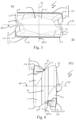
- the tangential milling cutting insert 1 has a first end surface 2 and a second end surface 3 which have a substantially rectangular basic shape, as can be seen in Fig: 1 and Fig. 3 . Further, the milling cutting insert 1 has two main side surfaces 4 extending between the long sides of the first and second end surfaces 2, 3, and two secondary side surfaces 6 extending between the short sides of the first and second end surfaces 2, 3. It should be noted that each of the first and second end surfaces 2, 3, the main side surfaces 4 and the secondary side surfaces 6 is segmented into a plurality of sub-surfaces, as will described more in detail below. The main side surfaces 4 and the secondary side surfaces 6 merge into one another via corner side surfaces 5.
- a through-hole 10 passes through the milling cutting insert 1 from one main side surface 4 to the other main side surface 4 and extends along a second symmetry axis S2 about which the milling cutting insert 1 has 2-fold rotational symmetry.
- a first symmetry axis S1 extends perpendicular to the second symmetry axis S2 and passes through the first and second end surfaces 2, 3.
- the milling cutting insert 1 has 2-fold rotational symmetry about the first symmetry axis S1.
- a third symmetry axis S3 extends perpendicular to both the first symmetry axis S1 and the second symmetry axis S2.
- the milling cutting insert 1 has 2-fold rotational symmetry about the third symmetry axis S3.
- a reference plane RP is spanned by the second symmetry axis S2 and the third symmetry axis S3. Consequently, the reference plane RP extends perpendicular to the first symmetry axis S1.
- a first symmetry plane SP12 is spanned by the first symmetry axis S1 and the second symmetry axis S2 and thus extends perpendicular to the third symmetry axis S3.
- a second symmetry plane SP13 is spanned by the first symmetry axis S1 and the third symmetry axis S3 and thus extends perpendicular to the second symmetry axis S2.
- Each of the first end surface 2 and the second end surface 3 has two diagonally opposed raised corners 8 and two diagonally opposed lowered corners 9.
- a first cutting edge section 11a and a second cutting edge section 11b are formed at the intersection of the first end surface 2 with main side surfaces 4, corner side surfaces 5 and secondary side surfaces 6.
- a third cutting edge section 11c and a fourth cutting edge section 11d are formed at the intersection of the second end surface 3 with main side surfaces 4, corner side surfaces 5 and secondary side surfaces 6.
- Each of the first to fourth cutting edge sections 11a, 11b, 11c, 11d is formed by a main cutting edge 12, a raised corner 8 and a wiper edge 13.
- the respective main cutting edge 12 comes closer to the reference plane RP with increasing distance from the adjacent raised corner 8, as can be seen in Fig. 2 .
- the respective wiper edge 13 does also come closer to the reference plane RP with increasing distance from the adjacent raised corner 8, as can be seen in Fig. 4 .
- the main cutting edge 12 and the wiper edge 13 of each of the first to fourth cutting edge sections 11a, 11b, 11c, 11d merge into one another through the respective raised corner 8 having an outwardly curved shape in top view onto the first end surface 2 and onto the second end surface 3, respectively.
- the raised corner 8 can have a specific corner radius.
- the main cutting edges 12 extend from the respective raised corner 8 all the way to a lowered corner 9.
- the wiper edges 13 extend only along a portion of the secondary side surfaces 6 and are connected to the adjacent lowered corner 9 via a transitional edge portion 14.
- the raised corners 8 are situated at a larger distance from the reference plane RP that the lowered corners 9.
- the first and second end surfaces 2, 3 Adjacent to the respective cutting edge sections 11a, 11b, 11c, 11d, the first and second end surfaces 2, 3 are provided with inwardly inclined rake surfaces coming closer to the reference plane RP with increasing distance from the respective cutting edge section 11a, 11b, 11c, 11d. Further, the first and second end surfaces 2, 3 each comprise a main seat surface 17.
- the main seat surface 17 is formed as a planar surface extending parallel to the reference plane RP. As can be seen in Fig. 2 , the main seat surface 17 is situated closer to the reference plane RP than the raised corners 8. Further, the lowered corners 9 are situated closer to the reference plane RP than the respective main seat surface 17. In the specific embodiment, the main seat surface 17 extends substantially from one secondary side surface 6 to the other secondary side surface 6.
- the main side surfaces 4 comprise main relief surfaces 16 in the region directly adjacent to the main cutting edges 12.
- the main relief surfaces 16 are inwardly inclined towards the first and second end surfaces 2, 3.
- the main relief surfaces 16 come closer to the second symmetry plane SP13 with increasing distance from the reference plane RP.
- the main relief surfaces 16 extend under an internal angle ⁇ ⁇ 90° to the reference plane RP, as can be seen in Fig. 4 .
- the internal angle ⁇ can be in the range 70° ⁇ ⁇ ⁇ 88°, for example.
- the secondary side surfaces 6 are formed as wiper relief surfaces 7 in the region directly adjacent the respective wiper edges 13.
- the wiper relief surfaces 7 are realized as planar surfaces extending parallel to the first symmetry axis S1. With increasing distance from the adjacent raised corner 8 each wiper relief surface 7 backs away from the first symmetry plane SP12 such that the wiper relief surface 7 and the first symmetry plane SP12 enclose a positive internal angle with each other, as can be seen in the top view of Fig. 3 .
- the secondary side surfaces 6 each comprise a groove 18 extending substantially parallel to the first symmetry axis S1 all the way from the first end surface 2 to the second end surface 3.
- the groove 18 can e.g. have the shape of a surface section of cylinder, as shown in the drawings. However, other shapes of the groove 18 are also possible.
- the transitional edge portions 14 connecting a respective wiper edge 13 to an adjacent lowered corner 9 have a curved and angled shape in top view, due to the groove 18. In the region adjacent the lowered corner 9, the transitional edge portion 14 is formed substantially straight in top view onto the respective first and second end surfaces 2, 3, as can be seen in Fig. 3 .
- the respective secondary side surface 6 is provided with a support surface 15 serving inter alia for axially positioning the milling cutting insert 1 in the insert seat of a tangential milling tool.
- the support surface 15 is formed as a planar surface. In the direction towards the second end surface 3, the support surfaces 15 associated with the first end surface 2 merge into the wiper relief surface 7 and the corner side surface 5 associated with the second end surface 3. Similarly, in the direction towards the first end surface 2, the support surfaces 15 associated with the second end surface 3 merge into the wiper relief surface 7 and the corner side surface 5 associated with the first end surface 2.
- the support surface 15 comes closer to the first symmetry plane SP12 with increasing distance from the reference plane RP.
- the support surface 15 associated with the transitional edge portion 14 along the first end surface 2 is inwardly inclined towards the first end surface 2.
- the support surface 15 encloses an acute internal angle ⁇ ⁇ 90° with the reference plane RP. It is advantageous if the internal angle ⁇ is in the range 60° ⁇ ⁇ ⁇ 88°.
- the support surface 15 is also inclined such that the support surface 15 comes closer to the first symmetry plane SP12 with increasing distance from the second symmetry plane SP13.
- the support surface 15 is also inwardly inclined in the direction from the groove towards the lowered corner 9.
- the support surface 15 encloses an acute internal angle ⁇ ⁇ 90° with the second symmetry plane SP13. It is advantageous if the internal angle ⁇ is in the range 65° ⁇ ⁇ ⁇ 88°.
- the tangential milling tool 1 comprises a holder 20 which can e.g. be made from steel.
- the holder 20 comprises a first end 20a adapted to be connected to a spindle of a milling machine (not shown) and a second end 20b provided with a plurality of insert seats 21 adapted for receiving the above described double-sided tangential milling cutting inserts 1.
- the tangential milling tool 100 comprises five insert seats for mounting the tangential milling cutting inserts 1, the tangential milling tool 100 may also have more (i.e. > 5) or less (i.e. ⁇ 5) such insert seats 21. However, the tangential milling tool 100 comprises at least one such insert seat 21.
- the tangential milling tool 100 can comprise a plurality of such insert seats distributed about the circumference of the holder 20.
- the tangential milling tool 100 may also have several rows of insert seats 21 staggered along an axial direction of the rotational axis R about which the tangential milling tool 100 rotates during machining, i.e. the tangential milling tool 100 may also be realized as a thus-called porcupine cutter.
- the insert seat 21 is formed such that the milling cutting insert 1 is oriented in a tangential orientation in which the second symmetry axis S2 of the milling cutting insert 1 is substantially radially oriented. It should be noted, however, that the second symmetry axis S2 is not oriented strictly in the radial direction with regard to the rotational axis R but is slightly tilted thereto. However, with regard to the axial direction, the radial direction and the tangential direction in relation to the rotational axis R of the tangential milling tool 100, the main directional component of the second symmetry axis S2 of the milling cutting insert 1 is in the radial direction.
- the insert seat 21 comprises a radial abutment surface 22 against which the abutment surface 19 of one of the main side surfaces 4 of the milling cutting insert 1 rests in order to prevent radial movement of the milling cutting insert 1 relative to the holder 20.
- a threaded bore 28 for receiving the threaded shank portion of a fastening screw 30 is formed in the radial abutment surface 22.
- the tangential milling cutting insert 1 is fastened to the insert seat 21 by the fastening screw 30 being passed through the through-hole 10 with its shank portion and by the screw head pressing against the internal surface of the through-hole 10, as is well known in the art.
Landscapes
- Engineering & Computer Science (AREA)
- Mechanical Engineering (AREA)
- Milling Processes (AREA)
Claims (10)
- Plaquette de coupe de fraisage tangentielle double face (1) pour fraisage d'angle, comprenant :une première surface d'extrémité (2),une seconde surface d'extrémité (3) opposée,deux surfaces latérales principales (4),deux surfaces latérales secondaires (6),un premier axe de symétrie (S1) passant à travers les première et seconde surfaces d'extrémité (2, 3) et s'étendant perpendiculairement à un plan de référence (RP) divisant la plaquette de coupe en deux moitiés, les première et seconde surfaces d'extrémité (2, 3) comportant chacune deux coins surélevés (8) diagonalement opposés et deux coins abaissés (9) diagonalement opposés etun trou débouchant (10) pénétrant dans les deux surfaces latérales principales (4) et s'étendant le long d'un deuxième axe de symétrie (S2),le premier axe de symétrie (S1) et le deuxième axe de symétrie (S2) couvrant un premier plan de symétrie (SP12),des première à quatrième sections d'arête de coupe (11a, 11b, 11c, 11d) étant formées à l'intersection de la première surface d'extrémité (2) avec les surfaces latérales principales (4) et les surfaces latérales secondaires (6) et à l'intersection de la seconde surface d'extrémité (3) avec les surfaces latérales principales (4) et les surfaces latérales secondaires (6),les première à quatrième sections d'arête de coupe (11a, 11b, 11c, 11d) comprenant chacune une arête de coupe principale (12), un coin surélevé (8) et une arête de planage (13) ; l'arête de planage (13) s'étendant à partir du coin surélevé (8) le long d'une partie de la surface latérale secondaire (6),une partie arête de transition (14) raccordant l'arête de planage (13) à un coin abaissé (9) adjacent étant formée le long de la surface latérale secondaire (6),la surface latérale secondaire (6) comportant, à côté de la partie arête de transition (14), une surface de support (15) plane qui se rapproche du premier plan de symétrie (SP12) à mesure que la distance par rapport au plan de référence (RP) augmente, etcaractérisée en ce que la plaquette de coupe a un troisième axe de symétrie (S3) s'étendant perpendiculairement au premier axe de symétrie (S1) et au deuxième axe de symétrie (S2), le premier axe de symétrie (S1) et le troisième axe de symétrie (S3) couvrant un second plan de symétrie (SP13),la surface de support (15) se rapprochant du premier plan de symétrie (SP12) à mesure que la distance par rapport au second plan de symétrie (SP13) augmente,les surfaces latérales secondaires (6) comprenant chacune une rainure s'étendant de la première surface d'extrémité (2) jusqu'à la seconde surface d'extrémité (3).
- Plaquette de coupe de fraisage tangentielle double face (1) selon la revendication 1,la plaquette de coupe ayant un troisième axe de symétrie (S3) s'étendant perpendiculairement au premier axe de symétrie (S1) et au deuxième axe de symétrie (S2) et le premier axe de symétrie (S1) et le troisième axe de symétrie (S3) couvrant un second plan de symétrie (SP13), etles surfaces latérales principales (4) étant formées, à côté des arêtes de coupe principales (12), comme des surfaces de dépouille principales (16), qui se rapprochent du second plan de symétrie (SP13) à mesure que la distance par rapport au plan de référence (RP) augmente.
- Plaquette de coupe de fraisage tangentielle double face (1) selon la revendication 2, une largeur (w) des surfaces de dépouille principales (16) diminuant à mesure que la distance par rapport au coin surélevé (8) adjacent augmente.
- Plaquette de coupe de fraisage tangentielle double face (1) selon la revendication 2 ou 3, les surfaces de dépouille principales (16) s'étendant le long des arêtes de coupe principales (12) des coins surélevés (8) en direction des coins abaissés (9) sur plus de 60 pour cent et moins de 95 pour cent de la longueur des arêtes de coupe principales (12).
- Plaquette de coupe de fraisage tangentielle double face (1) selon l'une quelconque des revendications précédentes, une surface d'assise principale (17) s'étendant parallèlement au plan de référence (RP) étant formée dans chacune des première et seconde surfaces d'extrémité (2, 3).
- Plaquette de coupe de fraisage tangentielle double face (1) selon la revendication 5, les surfaces d'assise principales (17) étant situées plus près du plan de référence (RP) que les coins surélevés (8) et les coins abaissés (9) étant situés plus près du plan de référence (RP) que les surfaces d'assise principales (17).
- Fraise tangentielle (100) pour fraisage d'angle, comprenant un support (20) comportant au moins un siège de plaquette (21) auquel est fixée une plaquette de coupe de fraisage tangentielle double face selon l'une quelconque des revendications précédentes.
- Fraise tangentielle (100) selon la revendication 7, le siège de plaquette (21) comprenant une surface d'appui radiale (22) contre laquelle une surface latérale principale (4) de la plaquette de coupe de fraisage tangentielle est en appui, une surface d'appui tangentielle (23) contre laquelle une surface d'assise principale (17) de la plaquette de coupe de fraisage tangentielle est en appui, et une surface d'appui axiale (24) contre laquelle une surface de support (15) est en appui.
- Fraise tangentielle (100) selon la revendication 7 ou 8, la surface d'appui tangentielle (23) et la surface d'appui axiale (24) du siège de plaquette (21) étant disposées à un angle intérieur (δ) aigu l'une par rapport à l'autre.
- Fraise tangentielle (100) selon l'une quelconque des revendications 7 à 9, la surface d'appui radiale (22) et la surface d'appui axiale (24) du siège de plaquette (21) étant disposées à un angle intérieur (ε) aigu l'une par rapport à l'autre.
Priority Applications (6)
| Application Number | Priority Date | Filing Date | Title |
|---|---|---|---|
| ES18179044T ES2926187T5 (en) | 2018-06-21 | 2018-06-21 | Double-sided tangential milling insert |
| EP18179044.5A EP3587012B2 (fr) | 2018-06-21 | 2018-06-21 | Insert de fraisage tangentiel à double face |
| CN201980041045.4A CN112334258B (zh) | 2018-06-21 | 2019-06-12 | 双面切向铣削刀片 |
| US17/251,488 US20210252615A1 (en) | 2018-06-21 | 2019-06-12 | Double-sided tangential milling cutting insert |
| PCT/EP2019/065314 WO2019243127A1 (fr) | 2018-06-21 | 2019-06-12 | Insert de fraisage tangentiel double face |
| JP2020570921A JP7179096B2 (ja) | 2018-06-21 | 2019-06-12 | 両面接線フライス切削インサート |
Applications Claiming Priority (1)
| Application Number | Priority Date | Filing Date | Title |
|---|---|---|---|
| EP18179044.5A EP3587012B2 (fr) | 2018-06-21 | 2018-06-21 | Insert de fraisage tangentiel à double face |
Publications (3)
| Publication Number | Publication Date |
|---|---|
| EP3587012A1 EP3587012A1 (fr) | 2020-01-01 |
| EP3587012B1 EP3587012B1 (fr) | 2022-08-03 |
| EP3587012B2 true EP3587012B2 (fr) | 2025-07-02 |
Family
ID=62748815
Family Applications (1)
| Application Number | Title | Priority Date | Filing Date |
|---|---|---|---|
| EP18179044.5A Active EP3587012B2 (fr) | 2018-06-21 | 2018-06-21 | Insert de fraisage tangentiel à double face |
Country Status (6)
| Country | Link |
|---|---|
| US (1) | US20210252615A1 (fr) |
| EP (1) | EP3587012B2 (fr) |
| JP (1) | JP7179096B2 (fr) |
| CN (1) | CN112334258B (fr) |
| ES (1) | ES2926187T5 (fr) |
| WO (1) | WO2019243127A1 (fr) |
Families Citing this family (4)
| Publication number | Priority date | Publication date | Assignee | Title |
|---|---|---|---|---|
| WO2020085245A1 (fr) * | 2018-10-23 | 2020-04-30 | 京セラ株式会社 | Insert de coupe, outil de coupe et procédé de fabrication de pièce coupée |
| JP6744599B1 (ja) * | 2019-03-01 | 2020-08-19 | 株式会社タンガロイ | 切削インサート |
| EP3950196A4 (fr) * | 2019-03-27 | 2022-05-25 | Sumitomo Electric Hardmetal Corp. | Insert de coupe |
| JP7029686B1 (ja) * | 2021-02-18 | 2022-03-04 | 株式会社タンガロイ | 切削工具 |
Citations (6)
| Publication number | Priority date | Publication date | Assignee | Title |
|---|---|---|---|---|
| KR20060135211A (ko) † | 2005-06-24 | 2006-12-29 | 대구텍 주식회사 | 절삭 인서트 |
| KR100718306B1 (ko) † | 2005-12-06 | 2007-05-16 | 한국야금 주식회사 | 절삭 인서트 |
| JP2008229745A (ja) † | 2007-03-16 | 2008-10-02 | Mitsubishi Materials Corp | 切削インサートおよびインサート着脱式転削工具 |
| US20130108388A1 (en) † | 2010-10-05 | 2013-05-02 | Kyocera Corporation | Cutting insert, cutting tool, and method of manufacturing machined product using them |
| JP2013121636A (ja) † | 2011-12-12 | 2013-06-20 | Sumitomo Electric Hardmetal Corp | 縦型刃先交換式切削インサートと隅削りフライスカッタ |
| WO2017047700A1 (fr) † | 2015-09-15 | 2017-03-23 | 三菱マテリアル株式会社 | Insert de coupe et outil de coupe de type lame remplaçable |
Family Cites Families (11)
| Publication number | Priority date | Publication date | Assignee | Title |
|---|---|---|---|---|
| SE502541C2 (sv) * | 1992-02-05 | 1995-11-06 | Sandvik Ab | Spånavskiljande skär med exakta lägesbestämmande mått, samt förfarande för dess framställning |
| JP3185519B2 (ja) * | 1994-02-28 | 2001-07-11 | 三菱マテリアル株式会社 | スローアウェイチップ及び切削工具 |
| IL165294A (en) * | 2004-11-18 | 2009-07-20 | Amir Satran | Milling cutting insert and milling cutter |
| SE531850C2 (sv) * | 2007-12-13 | 2009-08-25 | Seco Tools Ab | Skär och verktyg för spånavskiljande bearbetning |
| CN101474690B (zh) * | 2009-01-13 | 2010-10-06 | 株洲钻石切削刀具股份有限公司 | 端面铣削加工用可转位刀片 |
| JP5919832B2 (ja) * | 2011-01-18 | 2016-05-18 | 三菱マテリアル株式会社 | 切削インサートおよび刃先交換式切削工具 |
| DE102012108751A1 (de) * | 2012-09-18 | 2014-03-20 | Hartmetall-Werkzeugfabrik Paul Horn Gmbh | Schneideinsatz und Werkzeug zur spanenden Bearbeitung eines Werkstücks |
| AT14282U1 (de) * | 2014-09-03 | 2015-07-15 | Ceratizit Austria Gmbh | Doppelseitiger Schneideinsatz und Fräswerkzeug |
| JP6365363B2 (ja) * | 2015-03-17 | 2018-08-01 | 三菱マテリアル株式会社 | 切削インサート、切削インサート群および刃先交換式切削工具 |
| US10112242B1 (en) | 2017-04-21 | 2018-10-30 | Iscar, Ltd. | Ramping insert having non-positive cutting geometry and ramping tool |
| US10427225B2 (en) * | 2017-11-15 | 2019-10-01 | Kennametal Inc. | Tangentially mounted indexable cutting insert with segmented cutting edge and triangular-shaped margin |
-
2018
- 2018-06-21 EP EP18179044.5A patent/EP3587012B2/fr active Active
- 2018-06-21 ES ES18179044T patent/ES2926187T5/es active Active
-
2019
- 2019-06-12 WO PCT/EP2019/065314 patent/WO2019243127A1/fr not_active Ceased
- 2019-06-12 CN CN201980041045.4A patent/CN112334258B/zh active Active
- 2019-06-12 JP JP2020570921A patent/JP7179096B2/ja active Active
- 2019-06-12 US US17/251,488 patent/US20210252615A1/en not_active Abandoned
Patent Citations (6)
| Publication number | Priority date | Publication date | Assignee | Title |
|---|---|---|---|---|
| KR20060135211A (ko) † | 2005-06-24 | 2006-12-29 | 대구텍 주식회사 | 절삭 인서트 |
| KR100718306B1 (ko) † | 2005-12-06 | 2007-05-16 | 한국야금 주식회사 | 절삭 인서트 |
| JP2008229745A (ja) † | 2007-03-16 | 2008-10-02 | Mitsubishi Materials Corp | 切削インサートおよびインサート着脱式転削工具 |
| US20130108388A1 (en) † | 2010-10-05 | 2013-05-02 | Kyocera Corporation | Cutting insert, cutting tool, and method of manufacturing machined product using them |
| JP2013121636A (ja) † | 2011-12-12 | 2013-06-20 | Sumitomo Electric Hardmetal Corp | 縦型刃先交換式切削インサートと隅削りフライスカッタ |
| WO2017047700A1 (fr) † | 2015-09-15 | 2017-03-23 | 三菱マテリアル株式会社 | Insert de coupe et outil de coupe de type lame remplaçable |
Also Published As
| Publication number | Publication date |
|---|---|
| EP3587012B1 (fr) | 2022-08-03 |
| WO2019243127A1 (fr) | 2019-12-26 |
| CN112334258B (zh) | 2023-07-28 |
| US20210252615A1 (en) | 2021-08-19 |
| EP3587012A1 (fr) | 2020-01-01 |
| CN112334258A (zh) | 2021-02-05 |
| JP2021528261A (ja) | 2021-10-21 |
| ES2926187T3 (es) | 2022-10-24 |
| ES2926187T5 (en) | 2025-11-11 |
| JP7179096B2 (ja) | 2022-11-28 |
Similar Documents
| Publication | Publication Date | Title |
|---|---|---|
| CN111565874B (zh) | 用于车削的刀具系统和方法 | |
| JP5961646B2 (ja) | エンドミルカッタ | |
| EP3102354B1 (fr) | Insert de fraisage à double face et outil de fraisage | |
| EP3587012B2 (fr) | Insert de fraisage tangentiel à double face | |
| EP2633932B1 (fr) | Plaquette de fraisage et outil de coupe rotatif du type à remplacement de pointe de fraisage | |
| US5213452A (en) | Router type cutter | |
| SE530153C2 (sv) | Skär för svarvning med ett perifert land av konstant bredd | |
| US6619891B2 (en) | Milling tool having cutting members with different clearance angles | |
| US11850670B2 (en) | Milling cutting inserts | |
| US11806796B2 (en) | Cutting insert and cutting tool comprising cutting insert | |
| EP2981386B1 (fr) | Insert d'affûtage de fraise indexable à deux faces | |
| US10384275B2 (en) | Cutting tool and method for manufacturing the machined product | |
| US6733214B2 (en) | Milling tool and cutting bit therefor | |
| US6764257B2 (en) | Tool for milling, a milling body and method for milling | |
| JP2004195563A (ja) | 刃先交換式回転工具用インサート及び刃先交換式回転工具 | |
| US10537947B2 (en) | Cutting tool and method for manufacturing cut workpiece | |
| WO2023228741A1 (fr) | Outil de coupe et procédé de production de pièce coupée | |
| JP7045460B2 (ja) | 切削工具及び切削加工物の製造方法 | |
| JP7758646B2 (ja) | 切削工具及び切削加工物の製造方法 | |
| EP3722034A1 (fr) | Insert tangentielle de fraisage et outil de fraisage | |
| JPH09136208A (ja) | ろう付けエンドミル | |
| WO2019166133A1 (fr) | Plaquette de coupe indexable |
Legal Events
| Date | Code | Title | Description |
|---|---|---|---|
| PUAI | Public reference made under article 153(3) epc to a published international application that has entered the european phase |
Free format text: ORIGINAL CODE: 0009012 |
|
| STAA | Information on the status of an ep patent application or granted ep patent |
Free format text: STATUS: THE APPLICATION HAS BEEN PUBLISHED |
|
| AK | Designated contracting states |
Kind code of ref document: A1 Designated state(s): AL AT BE BG CH CY CZ DE DK EE ES FI FR GB GR HR HU IE IS IT LI LT LU LV MC MK MT NL NO PL PT RO RS SE SI SK SM TR |
|
| AX | Request for extension of the european patent |
Extension state: BA ME |
|
| STAA | Information on the status of an ep patent application or granted ep patent |
Free format text: STATUS: REQUEST FOR EXAMINATION WAS MADE |
|
| 17P | Request for examination filed |
Effective date: 20200602 |
|
| RBV | Designated contracting states (corrected) |
Designated state(s): AL AT BE BG CH CY CZ DE DK EE ES FI FR GB GR HR HU IE IS IT LI LT LU LV MC MK MT NL NO PL PT RO RS SE SI SK SM TR |
|
| GRAP | Despatch of communication of intention to grant a patent |
Free format text: ORIGINAL CODE: EPIDOSNIGR1 |
|
| STAA | Information on the status of an ep patent application or granted ep patent |
Free format text: STATUS: GRANT OF PATENT IS INTENDED |
|
| RIC1 | Information provided on ipc code assigned before grant |
Ipc: B23C 5/06 20060101ALN20220414BHEP Ipc: B23C 5/22 20060101AFI20220414BHEP |
|
| INTG | Intention to grant announced |
Effective date: 20220511 |
|
| GRAS | Grant fee paid |
Free format text: ORIGINAL CODE: EPIDOSNIGR3 |
|
| GRAA | (expected) grant |
Free format text: ORIGINAL CODE: 0009210 |
|
| STAA | Information on the status of an ep patent application or granted ep patent |
Free format text: STATUS: THE PATENT HAS BEEN GRANTED |
|
| AK | Designated contracting states |
Kind code of ref document: B1 Designated state(s): AL AT BE BG CH CY CZ DE DK EE ES FI FR GB GR HR HU IE IS IT LI LT LU LV MC MK MT NL NO PL PT RO RS SE SI SK SM TR |
|
| REG | Reference to a national code |
Ref country code: AT Ref legal event code: REF Ref document number: 1508342 Country of ref document: AT Kind code of ref document: T Effective date: 20220815 Ref country code: CH Ref legal event code: EP |
|
| REG | Reference to a national code |
Ref country code: DE Ref legal event code: R096 Ref document number: 602018038661 Country of ref document: DE |
|
| REG | Reference to a national code |
Ref country code: IE Ref legal event code: FG4D |
|
| REG | Reference to a national code |
Ref country code: ES Ref legal event code: FG2A Ref document number: 2926187 Country of ref document: ES Kind code of ref document: T3 Effective date: 20221024 |
|
| REG | Reference to a national code |
Ref country code: LT Ref legal event code: MG9D |
|
| REG | Reference to a national code |
Ref country code: NL Ref legal event code: MP Effective date: 20220803 |
|
| PG25 | Lapsed in a contracting state [announced via postgrant information from national office to epo] |
Ref country code: SE Free format text: LAPSE BECAUSE OF FAILURE TO SUBMIT A TRANSLATION OF THE DESCRIPTION OR TO PAY THE FEE WITHIN THE PRESCRIBED TIME-LIMIT Effective date: 20220803 Ref country code: RS Free format text: LAPSE BECAUSE OF FAILURE TO SUBMIT A TRANSLATION OF THE DESCRIPTION OR TO PAY THE FEE WITHIN THE PRESCRIBED TIME-LIMIT Effective date: 20220803 Ref country code: PT Free format text: LAPSE BECAUSE OF FAILURE TO SUBMIT A TRANSLATION OF THE DESCRIPTION OR TO PAY THE FEE WITHIN THE PRESCRIBED TIME-LIMIT Effective date: 20221205 Ref country code: NO Free format text: LAPSE BECAUSE OF FAILURE TO SUBMIT A TRANSLATION OF THE DESCRIPTION OR TO PAY THE FEE WITHIN THE PRESCRIBED TIME-LIMIT Effective date: 20221103 Ref country code: NL Free format text: LAPSE BECAUSE OF FAILURE TO SUBMIT A TRANSLATION OF THE DESCRIPTION OR TO PAY THE FEE WITHIN THE PRESCRIBED TIME-LIMIT Effective date: 20220803 Ref country code: LV Free format text: LAPSE BECAUSE OF FAILURE TO SUBMIT A TRANSLATION OF THE DESCRIPTION OR TO PAY THE FEE WITHIN THE PRESCRIBED TIME-LIMIT Effective date: 20220803 Ref country code: LT Free format text: LAPSE BECAUSE OF FAILURE TO SUBMIT A TRANSLATION OF THE DESCRIPTION OR TO PAY THE FEE WITHIN THE PRESCRIBED TIME-LIMIT Effective date: 20220803 Ref country code: FI Free format text: LAPSE BECAUSE OF FAILURE TO SUBMIT A TRANSLATION OF THE DESCRIPTION OR TO PAY THE FEE WITHIN THE PRESCRIBED TIME-LIMIT Effective date: 20220803 |
|
| REG | Reference to a national code |
Ref country code: AT Ref legal event code: MK05 Ref document number: 1508342 Country of ref document: AT Kind code of ref document: T Effective date: 20220803 |
|
| PG25 | Lapsed in a contracting state [announced via postgrant information from national office to epo] |
Ref country code: PL Free format text: LAPSE BECAUSE OF FAILURE TO SUBMIT A TRANSLATION OF THE DESCRIPTION OR TO PAY THE FEE WITHIN THE PRESCRIBED TIME-LIMIT Effective date: 20220803 Ref country code: IS Free format text: LAPSE BECAUSE OF FAILURE TO SUBMIT A TRANSLATION OF THE DESCRIPTION OR TO PAY THE FEE WITHIN THE PRESCRIBED TIME-LIMIT Effective date: 20221203 Ref country code: HR Free format text: LAPSE BECAUSE OF FAILURE TO SUBMIT A TRANSLATION OF THE DESCRIPTION OR TO PAY THE FEE WITHIN THE PRESCRIBED TIME-LIMIT Effective date: 20220803 Ref country code: GR Free format text: LAPSE BECAUSE OF FAILURE TO SUBMIT A TRANSLATION OF THE DESCRIPTION OR TO PAY THE FEE WITHIN THE PRESCRIBED TIME-LIMIT Effective date: 20221104 |
|
| PG25 | Lapsed in a contracting state [announced via postgrant information from national office to epo] |
Ref country code: SM Free format text: LAPSE BECAUSE OF FAILURE TO SUBMIT A TRANSLATION OF THE DESCRIPTION OR TO PAY THE FEE WITHIN THE PRESCRIBED TIME-LIMIT Effective date: 20220803 Ref country code: RO Free format text: LAPSE BECAUSE OF FAILURE TO SUBMIT A TRANSLATION OF THE DESCRIPTION OR TO PAY THE FEE WITHIN THE PRESCRIBED TIME-LIMIT Effective date: 20220803 Ref country code: DK Free format text: LAPSE BECAUSE OF FAILURE TO SUBMIT A TRANSLATION OF THE DESCRIPTION OR TO PAY THE FEE WITHIN THE PRESCRIBED TIME-LIMIT Effective date: 20220803 Ref country code: CZ Free format text: LAPSE BECAUSE OF FAILURE TO SUBMIT A TRANSLATION OF THE DESCRIPTION OR TO PAY THE FEE WITHIN THE PRESCRIBED TIME-LIMIT Effective date: 20220803 Ref country code: AT Free format text: LAPSE BECAUSE OF FAILURE TO SUBMIT A TRANSLATION OF THE DESCRIPTION OR TO PAY THE FEE WITHIN THE PRESCRIBED TIME-LIMIT Effective date: 20220803 |
|
| REG | Reference to a national code |
Ref country code: DE Ref legal event code: R026 Ref document number: 602018038661 Country of ref document: DE |
|
| PLBI | Opposition filed |
Free format text: ORIGINAL CODE: 0009260 |
|
| PLAX | Notice of opposition and request to file observation + time limit sent |
Free format text: ORIGINAL CODE: EPIDOSNOBS2 |
|
| PG25 | Lapsed in a contracting state [announced via postgrant information from national office to epo] |
Ref country code: SK Free format text: LAPSE BECAUSE OF FAILURE TO SUBMIT A TRANSLATION OF THE DESCRIPTION OR TO PAY THE FEE WITHIN THE PRESCRIBED TIME-LIMIT Effective date: 20220803 Ref country code: EE Free format text: LAPSE BECAUSE OF FAILURE TO SUBMIT A TRANSLATION OF THE DESCRIPTION OR TO PAY THE FEE WITHIN THE PRESCRIBED TIME-LIMIT Effective date: 20220803 |
|
| 26 | Opposition filed |
Opponent name: ISCAR LTD. Effective date: 20230502 |
|
| PG25 | Lapsed in a contracting state [announced via postgrant information from national office to epo] |
Ref country code: AL Free format text: LAPSE BECAUSE OF FAILURE TO SUBMIT A TRANSLATION OF THE DESCRIPTION OR TO PAY THE FEE WITHIN THE PRESCRIBED TIME-LIMIT Effective date: 20220803 |
|
| PG25 | Lapsed in a contracting state [announced via postgrant information from national office to epo] |
Ref country code: SI Free format text: LAPSE BECAUSE OF FAILURE TO SUBMIT A TRANSLATION OF THE DESCRIPTION OR TO PAY THE FEE WITHIN THE PRESCRIBED TIME-LIMIT Effective date: 20220803 |
|
| PLBB | Reply of patent proprietor to notice(s) of opposition received |
Free format text: ORIGINAL CODE: EPIDOSNOBS3 |
|
| PG25 | Lapsed in a contracting state [announced via postgrant information from national office to epo] |
Ref country code: MC Free format text: LAPSE BECAUSE OF FAILURE TO SUBMIT A TRANSLATION OF THE DESCRIPTION OR TO PAY THE FEE WITHIN THE PRESCRIBED TIME-LIMIT Effective date: 20220803 |
|
| PG25 | Lapsed in a contracting state [announced via postgrant information from national office to epo] |
Ref country code: MC Free format text: LAPSE BECAUSE OF FAILURE TO SUBMIT A TRANSLATION OF THE DESCRIPTION OR TO PAY THE FEE WITHIN THE PRESCRIBED TIME-LIMIT Effective date: 20220803 |
|
| REG | Reference to a national code |
Ref country code: CH Ref legal event code: PL |
|
| REG | Reference to a national code |
Ref country code: BE Ref legal event code: MM Effective date: 20230630 |
|
| PG25 | Lapsed in a contracting state [announced via postgrant information from national office to epo] |
Ref country code: LU Free format text: LAPSE BECAUSE OF NON-PAYMENT OF DUE FEES Effective date: 20230621 |
|
| REG | Reference to a national code |
Ref country code: IE Ref legal event code: MM4A |
|
| PG25 | Lapsed in a contracting state [announced via postgrant information from national office to epo] |
Ref country code: LU Free format text: LAPSE BECAUSE OF NON-PAYMENT OF DUE FEES Effective date: 20230621 |
|
| PG25 | Lapsed in a contracting state [announced via postgrant information from national office to epo] |
Ref country code: IE Free format text: LAPSE BECAUSE OF NON-PAYMENT OF DUE FEES Effective date: 20230621 |
|
| PG25 | Lapsed in a contracting state [announced via postgrant information from national office to epo] |
Ref country code: IE Free format text: LAPSE BECAUSE OF NON-PAYMENT OF DUE FEES Effective date: 20230621 Ref country code: CH Free format text: LAPSE BECAUSE OF NON-PAYMENT OF DUE FEES Effective date: 20230630 |
|
| PG25 | Lapsed in a contracting state [announced via postgrant information from national office to epo] |
Ref country code: BE Free format text: LAPSE BECAUSE OF NON-PAYMENT OF DUE FEES Effective date: 20230630 |
|
| PG25 | Lapsed in a contracting state [announced via postgrant information from national office to epo] |
Ref country code: BG Free format text: LAPSE BECAUSE OF FAILURE TO SUBMIT A TRANSLATION OF THE DESCRIPTION OR TO PAY THE FEE WITHIN THE PRESCRIBED TIME-LIMIT Effective date: 20220803 |
|
| PG25 | Lapsed in a contracting state [announced via postgrant information from national office to epo] |
Ref country code: BG Free format text: LAPSE BECAUSE OF FAILURE TO SUBMIT A TRANSLATION OF THE DESCRIPTION OR TO PAY THE FEE WITHIN THE PRESCRIBED TIME-LIMIT Effective date: 20220803 |
|
| PUAH | Patent maintained in amended form |
Free format text: ORIGINAL CODE: 0009272 |
|
| STAA | Information on the status of an ep patent application or granted ep patent |
Free format text: STATUS: PATENT MAINTAINED AS AMENDED |
|
| 27A | Patent maintained in amended form |
Effective date: 20250702 |
|
| AK | Designated contracting states |
Kind code of ref document: B2 Designated state(s): AL AT BE BG CH CY CZ DE DK EE ES FI FR GB GR HR HU IE IS IT LI LT LU LV MC MK MT NL NO PL PT RO RS SE SI SK SM TR |
|
| REG | Reference to a national code |
Ref country code: DE Ref legal event code: R102 Ref document number: 602018038661 Country of ref document: DE |
|
| PGFP | Annual fee paid to national office [announced via postgrant information from national office to epo] |
Ref country code: DE Payment date: 20250618 Year of fee payment: 8 |
|
| PGFP | Annual fee paid to national office [announced via postgrant information from national office to epo] |
Ref country code: GB Payment date: 20250618 Year of fee payment: 8 |
|
| PGFP | Annual fee paid to national office [announced via postgrant information from national office to epo] |
Ref country code: FR Payment date: 20250626 Year of fee payment: 8 |
|
| PG25 | Lapsed in a contracting state [announced via postgrant information from national office to epo] |
Ref country code: CY Free format text: LAPSE BECAUSE OF FAILURE TO SUBMIT A TRANSLATION OF THE DESCRIPTION OR TO PAY THE FEE WITHIN THE PRESCRIBED TIME-LIMIT; INVALID AB INITIO Effective date: 20180621 |
|
| PGFP | Annual fee paid to national office [announced via postgrant information from national office to epo] |
Ref country code: TR Payment date: 20250616 Year of fee payment: 8 |
|
| PG25 | Lapsed in a contracting state [announced via postgrant information from national office to epo] |
Ref country code: HU Free format text: LAPSE BECAUSE OF FAILURE TO SUBMIT A TRANSLATION OF THE DESCRIPTION OR TO PAY THE FEE WITHIN THE PRESCRIBED TIME-LIMIT; INVALID AB INITIO Effective date: 20180621 |
|
| PGFP | Annual fee paid to national office [announced via postgrant information from national office to epo] |
Ref country code: ES Payment date: 20250728 Year of fee payment: 8 |
|
| PGFP | Annual fee paid to national office [announced via postgrant information from national office to epo] |
Ref country code: IT Payment date: 20250624 Year of fee payment: 8 |
|
| REG | Reference to a national code |
Ref country code: ES Ref legal event code: DC2A Ref document number: 2926187 Country of ref document: ES Kind code of ref document: T5 Effective date: 20251111 |