EP3586427B1 - Elektromotor, innenrotor und rotorblech - Google Patents
Elektromotor, innenrotor und rotorblech Download PDFInfo
- Publication number
- EP3586427B1 EP3586427B1 EP18704545.5A EP18704545A EP3586427B1 EP 3586427 B1 EP3586427 B1 EP 3586427B1 EP 18704545 A EP18704545 A EP 18704545A EP 3586427 B1 EP3586427 B1 EP 3586427B1
- Authority
- EP
- European Patent Office
- Prior art keywords
- rotor
- recess
- clamping element
- magnet
- rotor magnet
- Prior art date
- Legal status (The legal status is an assumption and is not a legal conclusion. Google has not performed a legal analysis and makes no representation as to the accuracy of the status listed.)
- Active
Links
Images





Classifications
-
- H—ELECTRICITY
- H02—GENERATION; CONVERSION OR DISTRIBUTION OF ELECTRIC POWER
- H02K—DYNAMO-ELECTRIC MACHINES
- H02K1/00—Details of the magnetic circuit
- H02K1/06—Details of the magnetic circuit characterised by the shape, form or construction
- H02K1/22—Rotating parts of the magnetic circuit
- H02K1/27—Rotor cores with permanent magnets
- H02K1/2706—Inner rotors
- H02K1/272—Inner rotors the magnetisation axis of the magnets being perpendicular to the rotor axis
- H02K1/274—Inner rotors the magnetisation axis of the magnets being perpendicular to the rotor axis the rotor consisting of two or more circumferentially positioned magnets
- H02K1/2753—Inner rotors the magnetisation axis of the magnets being perpendicular to the rotor axis the rotor consisting of two or more circumferentially positioned magnets the rotor consisting of magnets or groups of magnets arranged with alternating polarity
- H02K1/276—Magnets embedded in the magnetic core, e.g. interior permanent magnets [IPM]
-
- H—ELECTRICITY
- H02—GENERATION; CONVERSION OR DISTRIBUTION OF ELECTRIC POWER
- H02K—DYNAMO-ELECTRIC MACHINES
- H02K2213/00—Specific aspects, not otherwise provided for and not covered by codes H02K2201/00 - H02K2211/00
- H02K2213/03—Machines characterised by numerical values, ranges, mathematical expressions or similar information
Definitions
- the invention relates to an electric motor, an inner rotor and a rotor lamination.
- Electric motors of the type of internal rotor motors have an external stator and an internal rotor with permanent magnets which is arranged in the external stator so that it can rotate.
- such internal rotor motors are used, for example, for drive tasks in which an electric motor must follow electrical commands with its movements very quickly, e.g. as a servo motor.
- the permanent magnets of the inner rotor which are arranged in a laminated core assigned to the inner rotor, must not rattle and must not shift in the axial direction even at higher speeds, i.e. they must be securely fixed in the laminated core in the axial and radial direction.
- extreme areas of application require the magnets to remain firmly in the inner rotor in the event of impacts with an acceleration of 50 g.
- the permanent magnets can be glued into the laminated core, or a suitable locking washer covering the magnets can also be attached to both ends of the laminated core.
- the DE 10 2011 101 730 A1 shows an internal rotor motor in which the permanent magnets are elastically clamped in an associated laminated core. This is done in that holding sections, which are provided on the outer circumference of the laminated core, are pressed in (notched, embossed) radially inwards by means of a tool.
- the disadvantage here is that the resilient indentations (notches, impressions) can spring back over the service life of the internal rotor motor, so that the permanent magnets can become loose in the recesses and thus rattle or fall out of the recesses.
- the DE 10 2007 029 719 A1 shows an internal rotor motor in which a resilient attachment is provided on corresponding recesses of a laminated core assigned to the inner rotor, which in the unloaded state deflects into a respective assigned recess.
- This resilient tab is connected to the core on one side and the other end is free.
- the resilient attachment When a corresponding permanent magnet is pushed into the recess, the resilient attachment is subjected to a force from the permanent magnet and is thus elastically deformed.
- the resilient attachment can in turn exert an associated spring force F against the permanent magnet, which clamps it in the recess.
- the resilient attachments also spring back over the service life of the internal rotor motor, so that the permanent magnets can loosen in the recesses even when these resilient attachments are used and can therefore rattle or fall out of the recesses.
- the DE 10 2012 016 927 A1 discloses an inner rotor for an electric motor, in which the rotor magnets are fixed via a clamping element. An additional component is required, which also increases the costs.
- the WO 2014/147102 A2 discloses an internal rotor motor with a laminated core which has at least one first recess and at least one second recess. A arranged in the first recess rotor magnet is fixed by introducing a clamping element in the second recess and thereby a between the recesses arranged clamping member is deformed and subjected to a force directed towards the rotor magnet.
- this solution requires additional components or a complex design of the laminated core.
- An internal rotor motor with a laminated core is also disclosed, in which a radial force is applied to the rotor magnets via the shaft oversize via a clamping element integrated in the laminated core. This solution is poorly suited to small rotor diameters because of the complex sheet metal geometry. In addition, high tensile stresses occur in the laminated core.
- inner rotors or electric motors with inner rotors are from the documents DE 10 2005 041 676 A1 , DE 10 2015 207 663 A1 and WO 2008/065146 A1 known.
- the object of the present invention is achieved by an inner rotor according to claim 1 and an electric motor according to claim 14. This enables the rotor magnet to be held securely, and the spring-back described above can be prevented.
- the inner rotor according to the invention is characterized by the features according to claim 1. Further advantageous developments of the inner rotor are determined by the features of claims 2 to 13.
- the electric motor according to the invention is characterized by the features of claim 14.
- left, right, top and bottom refer to the respective drawing figure and can vary from one drawing figure to the next depending on the selected orientation (portrait or landscape). Parts that are the same or have the same effect are denoted by the same reference symbols in the various figures and are usually only described once.
- FIG. 1 shows an electric motor 100 provided with a housing 22, which is preferably designed in the manner of an electronically commutated internal rotor motor.
- This has an outer stator 28 arranged in the housing 22 and an inner rotor 150 arranged in the outer stator 28 so that it can rotate. This is separated from the outer stator 28 by a magnetically effective air gap.
- the housing 22 has, for example, a cylindrical housing part 24 , an A end shield 26 and a fastening flange 29 .
- a stator core 27 of the external stator 28 is arranged in the cylindrical housing part 24 , and the end windings of the stator core 27 are indicated by the reference symbols 30 and 32 .
- the stator core 27 is designed as a laminated core 27 with a plurality of laminations or laminations—only indicated schematically—and is referred to below as “laminated stator core 27” for better understanding of the description.
- This laminated stator core 27 can be embedded in a winding or insulating body 25, which can be designed, for example, in the manner of a plastic encapsulation.
- the outer stator 28 has an inner recess 34 in which at least one and preferably a plurality (eg 2, 4, 6, 8) of rotor magnets 221 provided rotor core 200 (English: rotor core) of the inner rotor 150 is arranged.
- this rotor core 200 is designed as a laminated core with a plurality of laminations or laminated cores 310, so that it is referred to below as “laminated rotor core 200” for better understanding of the description. It has at least one and preferably a plurality of first pockets 210 for receiving the rotor magnets 221, in which the rotor magnets 221 are arranged. According to one embodiment, these are permanent magnets.
- the laminated rotor core 200 is arranged on a rotor shaft 40 which is preferably pressed into the laminated rotor core 200 .
- the rotor shaft 40 has a free, outer drive end 42 and an inner shaft end 44 and is configured for rotation about an axis of rotation 43 .
- a seal 46 is provided for the rotor shaft 40 in the A end shield 26 .
- An inner ring 60 of this roller bearing 54 is arranged around the rotor shaft 40 in the region of the drive end 42, preferably pressed on.
- the inner shaft end 44 of the rotor shaft 40 is arranged in a B end shield 66 which is fastened to an open end of the cylindrical housing part 24 opposite the A end shield 26 .
- the B end shield 66 has a recess 68 provided with an annular shoulder 78 for an outer ring 70 of a roller bearing 72, the inner ring 74 of which is fastened on the shaft end 44.
- the rotor shaft 40 has an annular collar 88 with which it is against a - in 1 left - side of the inner ring 74 is present.
- - in 1 On the right-hand side is a molded piece 80 made of brass, for example, which is pressed in the direction of the rotor shaft 40 by a countersunk head 110 of a countersunk screw 82 and is configured approximately in the shape of a ring.
- the screw 82 is screwed into an internal thread 84 of the shaft end 44 and thereby presses the shaped piece 80 in the direction of the inner ring 74.
- the outer ring 70 of the roller bearing 72 serves a preferably flat, ring-shaped part 90, which is fastened by several evenly distributed screws 92, e 1 to the left - against the shoulder 78 presses.
- a control magnet 112 is preferably fastened in a recess 87 of the screw head 110 .
- This is e.g. on his - in 1 right - side provided with a magnetization pattern and is used to control magnetoresistive resistors, which are arranged on a housing cover 117 and are used to detect a respective rotational position of the inner rotor 150 in order to be able to precisely control the shape and commutation of motor currents in the outer stator 28.
- the housing cover 117 is fastened to the B end shield 66 and is used to seal the housing 22 preferably tightly.
- the electric motor 100 described above cannot only be referred to as an electronically commutated internal rotor motor, but can also be referred to in various ways.
- the electric motor 100 can also be referred to as a permanently excited synchronous internal rotor machine, or as an electronically commutated motor, or as an electric motor with permanent magnetic excitation.
- the electric motor 100 can also be constructed differently, and in particular in the case of very small electric motors 100, other bearings and a different mounting of the bearings can be used, for example injected bearings.
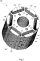
- the rotor laminated core 200 has a first axial end 201 and a second axial end 202 opposite the first axial end 201.
- the rotor laminated core 200 has rotor laminations 310, and these have to form the pockets 210 first recesses 211.
- a through opening 240 for receiving the rotor shaft 40 is central 1 educated.
- Clamping members 291 are provided in the pockets 210 and protrude into the pockets 210 . Two clamping links 291 can be seen in the left pocket.
- the rotor laminations 310 of the rotor lamination stack 200 have first rotor laminations 311 and second rotor laminations 312 , with the clamping members 291 being provided on the first rotor laminations 311 .
- Rotor laminations 310 preferably have at least one centering index recess 209 in order to enable a predetermined arrangement of rotor laminations 310, in particular for centering rotor lamination stack 200.
- Indentations 208 are indicated on the first axial side 201, which are produced by embossing the rotor laminations 310 with one another.
- the rotor laminations 310 are preferably connected to one another by these embossings.
- the plurality of recesses 211 and the through-opening 240 for receiving a shaft and optionally further recesses such as the second recesses 230 of 3 can be formed by stamping or by laser cutting.
- the laminations 310 can be fastened to one another in any desired manner to form the laminated rotor core 200, for example by welding and/or stamping.
- the laminated rotor core 200 is provided with a plurality of first recesses 211-216 for receiving a plurality of rotor magnets 221, the plurality of first recesses 211-216 illustratively comprising six recesses 211, 212, 213, 214, 215, 216.
- first recesses 211 can also be provided.
- Precisely one rotor magnet 221 is preferably arranged in each first recess 211, but a plurality can also be arranged.
- the assigned number of stator poles depends on Motor type (single-phase or three-phase).
- Each of the first recesses 211 accommodates one rotor magnet of the plurality of rotor magnets 221, for example the first recess 211 receives the rotor magnet 221.
- the laminated rotor core 200 also has a plurality of second recesses 230, the plurality of second recesses 230 illustratively having six recesses 231, 232, 233, 234, 235, 236.
- the second recesses 230 are each adjacent to the corresponding first recesses 211 to 216 in the radial direction.
- the first recess 211 is adjacent to the second recess 231 in the radial direction, etc.
- an alternative embodiment with a smaller angular extension is shown by dashed lines.
- the second recesses according to the alternative embodiment thus only extend within the dashed lines.
- the second recesses 230 are therefore smaller.
- alternative embodiments with a preferred smaller angular extension are shown schematically by dashed lines.
- each first recess 211-216 preferably being assigned at least one second recess 230, particularly preferably exactly one second recess 230
- the clamping members 290 are preferably designed as areas of the laminated rotor core 200 .
- each of the first recesses 211, 212, 213, 214, 215, 216 is assigned a web-shaped clamping element 290.
- the reference numeral 291 which acts upon the associated rotor magnet 221 after it has been installed with a spring force acting radially outward.
- the plurality of clamping members 290 is formed in the area between the plurality of second recesses 230 and the associated plurality of first recesses 211-216. Accordingly, the clamping member 291 is formed between the opening 231 and the recess 211, for example.
- first recess 211 is arranged in the region between the through-opening 240 and the second recess 231, i.e. the second recess 231 is further outward in the radial direction than the first recess 211.
- the diameter of the laminated rotor core is 22 mm
- the extension of the magnets 221 in the radial direction is 1.9 mm and in the tangential direction 7.8 mm.
- the radial extent of the second recesses 230 in the fully assembled state is approximately 0.8 mm.
- the sheet metal thickness is 0.35 mm.
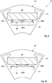
- FIG 4 shows an enlarged detail 300 of the first rotor lamination 311 of FIG 3 , the rotor lamination 311 being shown in a relaxed state Z1 without the rotor magnet being pushed in.
- the first recess 211 is designed to accommodate a rotor magnet 221 .
- the rotor magnet 221 has an extension X in the tangential direction and an extension Y in the radial direction.
- the recess 211 preferably has shoulders 351 and 352 which fix the rotor magnet in the tangential direction or limit its movement in the tangential direction.
- the distance between shoulders 351 and 352 preferably essentially corresponds to the extension X in the tangential direction of the rotor magnet 221.
- An extension of the first recess 211 in the radial direction corresponds in some areas to the extension Y of the rotor magnet 221 in the radial direction.
- the first recess 211 preferably has a first area 271L and a second area 271R, which are not filled by the rotor magnet 221 will.
- the first area 271L and the second area 271R cause the ridges between the first recesses 211-216 to become thinner. This reduces grooving.
- embodiments without the first area 271L and the second area 271R are also possible, with the shoulders 351, 352 then preferably being extended up to the radially outer wall of the first recess 211.
- An extent of the second recess 231 in the tangential direction is preferably at least 40% of the extent X of the rotor magnet 221 in the tangential direction. In another embodiment, the extent of the second recess 231 in the tangential direction is at least 50% of the extent X of the rotor magnet 221 in the tangential direction, or even at least 66% of the extent X of the rotor magnet 221 in the tangential direction. In further embodiments, in which the second recess 231 is further outward in the radial direction than the first recess 211, the extent of the second recess 231 in the tangential direction can even be equal to or greater than the extent X of the rotor magnet 221 in the tangential direction.
- the extent of the second recess 231 in the tangential direction is preferably selected such that the respective adjacent second recesses are at least partially spaced apart in order to achieve a good spring effect.
- the maximum tangential extension is therefore dependent on the geometry of the rotor core 200 and the arrangement of the second recesses 231 relative to the first recesses 211.
- the clamping member 291 has a first end portion 291L and a second end portion 291R, each of which is connected to the remainder of the rotor lamination 311, with a middle portion 291M being provided between the first end portion 291L and the second end portion 291R.
- the first recess 211 and the second recess 231 have a common central axis 405 which runs through the center point of the rotor lamination 310 .
- the centers of both recesses are therefore on a line that runs through the center of the Rotor lamination 310 runs.
- Both recesses are mirror-symmetrical with respect to the central axis 405, and their mirror axes coincide in the form of the central axis.
- embodiments are also conceivable in which the center points of the first recess 211 and the second recess 231 are shifted relative to one another in the tangential direction.
- Embodiments are also conceivable in which the second recess 231 is not mirror-symmetrical. Embodiments with a combination of the features mentioned are also possible.
- the rotor magnets 221 are preferably essentially cuboid, but they can also be curved.
- a resilient web-shaped clamping element 291 is formed between the first recess 211 and the second recess 231, which are adjacent in the radial direction.
- the clamping member 291 extends from the first recess 211 to the second recess 231.
- the clamping member 291 has a local bulge 292 in the radial direction. This bulge 292 locally reduces the radial extent of the first recess 211 , which is smaller than the radial extent Y of the rotor magnet 221 in the area of the local bulge 292 .
- the clamping member 291 is curved outwards in the radial direction.
- the delimitation of the second recess 231 lying further outward in the radial direction is also curved radially outward.
- the clamping element 291 When the rotor magnet 221 is inserted into the recess 211, the clamping element 291 is elastically deformed in the radial direction towards the center of the laminated core 200, so that a restoring force F is generated which acts against the radially inner side of the rotor magnet 221 and forces it with a radial downward direction externally acting spring force applied. As a result, the rotor magnet 221 is fixed or clamped in the recess 211 in the radial direction.
- the clamping member 291 is designed to hold the rotor magnet 221 in the first recess 211 on the radially inner side of the rotor magnet 221 to jam only in a partial area.
- embodiments are also possible in which the rotor magnet 221 is clamped on the radially inner side over its entire extent X, in particular also in the case of second recesses 231 which are provided outside of the first recesses 211 .
- the relationships described above apply analogously, but mirrored, i.e. the clamping member 291 is curved or bulged inward in the radial direction and acts on the radially outer one side of the rotor magnet 221.
- the first recess 211 has a first surface F1 and the second recess 231 has a second surface F2.
- the clamp member 291 transitions to a clamped state Z2 in which the first area F1 increases and the second area F2 decreases.
- the ratio of the first area F1 of the first recess 211 to the second area F2 of the second recess 231 is smaller in the relaxed state Z1 than in the tensioned state.
- figure 5 shows a top view of a second rotor lamination 312 and a first rotor lamination 311 arranged underneath, and 6 shows an enlarged section.
- the first rotor lamination 311 has a first contour and the second rotor lamination 312 has a second contour.
- the contour of the first rotor lamination 311 protrudes into the pocket 210 in the area of the clamping element 291 of the first rotor lamination 311.
- the first rotor lamination 311 can be pushed into the pocket 210 when a rotor magnet 221 is pressed in springs inwards and exert pressure on the rotor magnet 221 through this tension and hold it.
- FIG 7 shows the laminated rotor core 200 from FIG 2 , and 8 an enlarged view of a detail VIII of 7 .
- the laminated rotor core 200 has three first rotor laminations 311. It is advantageous not only to use first rotor laminations 311, since the second recesses 231 create a magnetic resistance for the magnetic flux, which reduces the power of the motor.
- Six second rotor laminations 312 are arranged between the upper first rotor lamination 311 and the first axial end 201 of the rotor lamination stack 200, and six second rotor laminations 312 are likewise provided between the lower first rotor lamination 311 and the second axial end 202 of the rotor lamination stack 200. Studies have shown that it is advantageous to provide at least five second rotor lamination sheets 312 (without clamping elements) on the first axial end 201 and on the second axial end 202, since this leads to a noise reduction.
- first rotor laminations 311 can be provided at the 7th, 29th and 51st positions, with a deviation of the order of +/-1 not significantly disturbing the symmetry.
- the clamping members 291 protrude by 0.125 mm into the pockets 210, so in this area they protrude beyond the contour of the second rotor laminations 312 or partially cover the contour of the first recesses 211 of the second rotor laminations 312.
- the clamping members 291 can spring into the associated second recess 231 and thus exert pressure on the rotor magnet 221 perpendicular to the axis.
- the deformation of the clamping member 291 is preferably largely elastic, plastic deformation can also occur in areas of very severe deformation. After a—usually undesired—removal of the rotor magnet 221, the clamping member 291 may no longer spring back fully into the relaxed position.
- FIG 9 shows a section of the first rotor lamination 311 of FIG 3 with the rotor magnet 221 clamped by the clamping member 291 in the recess 211.
- the rotor lamination 311 is in a stressed state Z2, and the rotor magnet 221 can be permanently fastened in the opening 211.
- the clamping member 291 is deformed by the rotor magnet 221 so that the extent of the first recess 211 in the radial direction over the entire tangential extent X of the rotor magnet 221 corresponds to the extent Y of the rotor magnet 221 in the radial direction or is slightly larger.
- the plastic expansion of the clamping member 291 caused by the rotor magnet 221 is shown.
- the maximum plastic elongation is about 11%, which is well below the elongation at break of the sheet metal, which is about 15%.
- the maximum stress occurs at the outer end portions 291L, 291R of the clamping member 291 in the areas adjacent to the second recess 231.
- FIG on. the load in the middle section 291M of the clamping member 291 on the side facing the rotor magnet 221 is only about half as large.
- the deformation of the clamping element 291 generates a restoring force F, which acts against the radially inner side of the rotor magnet 221 and acts on it with a spring force acting radially outward.
- the clamping element 291 is designed to clamp the rotor magnet 221 only in sections with the associated clamping force F in the recess 211 in order to avoid damage to the usually brittle rotor magnet 221 .
- the plastic strain looks qualitatively corresponding, with the outer strain areas correspondingly occurring further inwards.
- FIG. 10 shows the section 9 and the hydrostatic stress distribution prevailing therein. It can be seen that in the central region of the clamping element 291 there is a compressive stress on the side facing the rotor magnet 221 and a tensile stress on the side facing away from the rotor magnet 221 , ie the side adjoining the second recess 231 . Likewise shows 10 that in the outer edge regions of the clamping member 291 on the side facing the rotor magnet 221 there is a tensile stress and on the side facing away from the rotor magnet 221 there is a compressive stress. In the areas of the clamping member 291 with maximum plastic expansion, there is a compressive stress. Material breakage is therefore not to be feared.
- the maximum amount of plastic strain is determined by the shape, such as the radius or curvature at the outer portions of the clamping member, both radially inward and radially outward.
- the maximum elongation can also be influenced by the shape of the clamping element (straight or curved: different thicknesses) and the shape (eg width) of the second recess and also whether this occurs in an area with tensile stress or compressive stress.
- the hydrostatic stress distribution looks qualitatively corresponding, with the outer pressure areas correspondingly occurring further inwards.
- FIG. 11 shows an enlarged detail of a second embodiment of a first rotor lamination 711 for a rotor laminated core 600.
- the recesses 611, 631 and the through-opening 640 can be punched out or cut by means of a laser, for example.
- the laminations 610 can be fastened to one another in any desired manner to form the laminated rotor core 600, for example by welding or stamping.
- soft iron or another soft-magnetic material can also be used to form the laminated rotor core 600.
- the enlarged detail of the laminated core 600 shows in particular the clamping element 691 arranged in the area between the first recess 611 and the second recess 631, in the central part of which there is a local bulge 692 on the side facing away from the second recess 631.
- the bulge 692 locally reduces the radial extent of the first recess 611 so that in the area of the bulge 692 it is smaller than the radial extent Y of an associated rotor magnet 621 .
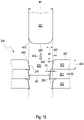
- FIG. 12 shows the section of 11 with the rotor magnet 621 clamped by the clamping element 691 in the recess 611. By pressing in the rotor magnet 621, the clamping element 691 is deflected or deformed.
- a restoring force F is generated, which acts against the radially inner side of the rotor magnet 621 and permanently with a applied radially outwardly acting spring force.
- the clamping element 691 clamps the rotor magnet 621 only in the area of the bulge 692 with the associated clamping force F in the recess 611.
- the deformation looks qualitatively corresponding, with the outer deformed areas shown not being deformed or only slightly deformed, while the inner areas are more so. This highlights the effect of the smaller second recesses 231 according to the alternative embodiment.
- the rotor magnet 221 has a bevel or chamfer 410 at least on the insertion side, in order to facilitate the insertion 412 into the first recess 211 or the required maximum press-in force for pressing in the rotor magnet 221 and the deflection 432 of the clamping member 291 to decrease.
- the chamfer 410 can be produced, for example, by vibratory grinding for a plurality of rotor magnets 221 at the same time. The force required to press in the rotor magnet 221 is higher, the smaller the radius of the ground edge of the rotor magnet 221 or the local curvature.
- the edge of the first recess 211 also has a chamfer 420 .
- This can be produced during the manufacture of the rotor lamination 310 by edge infeed during the stamping process and can be varied by the width of the stamping tool.
- the indentation width 421 is preferably between 10% and 40% of the sheet thickness 430, more preferably about 30% of the sheet thickness 430.
- the indentation depth 422 is preferably between 8% and 30% of the sheet thickness 430, more preferably about 20% of the sheet thickness 430.
- the edge indentation is somewhat exaggerated.
- the sheet metal thickness 430 is preferably in the range from 0.1 mm to 3.0 mm, more preferably in the range from 0.2 mm to 0.5 mm, in the exemplary embodiments it is preferably 0.35 mm.
- the pressing force can be monitored in order in particular to identify and possibly separate out rotor magnets 221 that are too loosely seated.
- a second rotor lamination 312 viewed inward from the outside (first axial end 201), a second rotor lamination 312, then a first rotor lamination 311 with a clamping member, and then a second rotor lamination 312 again are provided.
- This enables the clamping member 291 to be deflected by the rotor magnet 221 , the deflection being guided by the adjacent second rotor laminations 312 in a direction perpendicular to the axis of the rotor core 200 .
- the rotor laminations 311, 312 form the rotor laminated core 200 with the at least one pocket 210 for the rotor magnet 221.
- the rotor magnet 221 has a chamfer 410 on an axial end 222 with a draw-in width B1 in the radial direction. Before being inserted into the pocket 210, the rotor magnet 221 has a maximum oversize O1 in the radial direction relative to the pocket, where: The ratio of B1 to O1 is in the range 1.5 .. 4.0.
- This ratio allows for good insertion of the rotor magnet 221 into the pocket and it will not butt flat against a rotor lamination 311, 312.
- the rotor magnet 221 is not cuboid, but has a curved cross section.
- the clamping element is also of curved design, protruding even more into the first recess 211 in the relaxed state (without the rotor magnet 221).
- Analogous to 4 can here the extension X of the rotor magnet 221 in the tangential direction and an extension R2 of the second recess 231 in the tangential direction to be specified.
- the extent R2 is of a similar size to the extent X, with R2 being approximately 0.9X.
- the ratio of the extension R2 of the second recess 230 to the extension X of the rotor magnets 221 to be pressed into the first rotor lamination 311 (extension between the shoulders, cf. 4 ) is approximately 0.5.
- a ratio of at least 0.4 (corresponding to 40%), preferably at least 0.45, has generally proven advantageous.
- a ratio of at most 1.2, preferably at most 0.9, more preferably at most 0.7, has proven to be advantageous, it being possible for the ratio to be greater when the second recess 230 is arranged radially outside of the first recess 211 .
- FIG. 16 shows a first rotor lamination 311, which is covered by a second rotor lamination 312.
- the clamping member 291 is largely covered by the second rotor lamination 312, and as a result, deformation in the axial direction when the rotor magnet is pressed in is prevented or largely reduced.
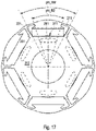
- 17 shows the rotor laminations 311, 312 accordingly 16 , wherein the position of the rotor magnet 221 is indicated schematically.
- the extensions were considered in the tangential direction are in 17 the angular extent phi_RM of the rotor magnet 221 and the angular extent phi_R2 of the second recess 230 are considered, with the maximum angular extent being considered in each case as the angular extent.
- the ratio phi_R2 / phi_RM is therefore 0.65.
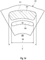
- An inner rotor 150 for an electric motor 100 has a laminated rotor core 200; 600 with a plurality of rotor laminations 310, which laminated rotor core 200; 600 has a plurality of pockets 210, in which pockets 210 each have a rotor magnet 221; 621 is at least partially arranged, which rotor laminations first recesses 211; 611 for forming the pockets 210, which rotor laminations 310 have at least one first rotor lamina 311, which first rotor laminations 311 have at least one second recess 231-236; 631, which second recess 231-236; 631 of a first recess 211-216; 611 is assigned, wherein between the second recess 231-236; 631 and the associated first recess 211-216; 611, a resilient bar-shaped clamping member 291; 691 is formed, which clamping member 291; 691 through the associated rotor magnet 221, 621 to the second recess 231-2
- the ratio of the angular extent phi_R2 of the second recess 230 to the angular extent phi_RM of the associated rotor magnet 221 is in the range from 0.4 to 0.8, preferably in the range from 0.5 to 0.8. In this area, the distribution of the stresses could be achieved particularly well and at the same time a sufficient holding force could be generated. Targeted investigations using the FEM method (Finite Element Method) have shown that the stress in the Rotor lamination increases as the ratio decreases and this can lead to failure of the rotor magnets to be pushed in.
- the holding force for the rotor magnets decreases, and this may result in poor holding of the rotor magnet, or excessive use of clamp member rotor laminations.
- the range of 0.4 to 0.5 has proven advantageous for very large internal rotors.
- the range from 0.5 to 0.8 is advantageous for smaller, medium-sized and larger inner rotors, with a value of 0.65 being particularly preferred in an optimized embodiment.
- the second recess is 231-236; 631 to the first recess 211-216; 611 adjacent in the radial direction.
- the clamping member 291 can spring well into the second recess in the radial direction.
- the clamping member 291 separates the first recess 211-216; 611 and the second recess 231-236; 631 within the first rotor lamination 311 completely from each other. This increases the stability of the clamping member 291 and allows for greater tension build-up.
- the second recess 231; 631 and the associated first recess 211; 611 a common central axis. A more even stress distribution in the clamping member 291 can thereby be achieved.
- the extension of the second recess 231; 631 in the tangential direction at least 40% of the extent of the rotor magnet 221; 621 in the tangential direction, preferably at least 45%. In this way, a good distribution and a limitation of the tension arising in the clamping member 291 can be achieved.
- the clamping member 291; 691 has a first end portion 291L and a second end portion 291R, which respectively are connected to the remaining area of the rotor lamination 311, with a middle section 291M being provided between the first end section 291L and the second end section 291R.
- the clamping member is integrated into the rotor lamination and it can interact with the rotor lamination at both ends as part of the rotor lamination.
- a preferred embodiment prevail at the clamping member 291; 691 by the tension or deflection to the second recess 231-236; 631 towards the middle portion 291M of the clamping member 291; 691 at least in some areas on the side facing the rotor magnet 221 a compressive stress and on the side facing away from the rotor magnet 221 a tensile stress.
- This arrangement of compressive stress and tensile stress can generate a force on the rotor magnet.
- a preferred embodiment prevail at the clamping member 291; 691 through the voltage to the second recess 231-236; 631 toward the first end portion 291L and the second end portion 291R of the clamping member 291; 691 on the side facing the rotor magnet 221 a tensile stress and on the side facing away from the rotor magnet 221 a compressive stress.
- This arrangement of voltages allows for a good build up of opposing voltages in the mid-range.
- the central portion 291M is on top of the first recess 211-216; 611 side facing convexly curved at least in sections.
- the central portion 291M is on that of the second recess 231-236; 631 side facing is formed concavely curved at least in sections.
- the central portion 291M has a projection which fits into the first recess 211-216; 611 protrudes into it. This enables concentrated force to be exerted on the rotor magnet and thus higher contact pressure.
- the rotor magnet 221; 621 to the clamping member 291; 691 facing first side and the clamping member 291; 691 has, in the tensioned state, a shape which is not exactly complementary to the shape of the first side, in order to thereby hold the rotor magnet 221; 621 in the first recess 211; 611 to jam on the first page only in a partial area.
- the rotor core 200 has a through-opening 240 for receiving a shaft 40, and the second recess 231 is arranged in the region between the through-opening 240 and the associated first recess 211.
- the rotor magnets can be arranged close to the outer circumference of the rotor and a greater magnetic flux can thereby be generated.
- the clamping member 291; 691 a local bulge 292; 692 in the radial direction. This leads to an increase in the holding pressure on the rotor magnets.
- the first rotor lamination 311 has a first contour
- the rotor lamination 310 has at least one second rotor lamination 312, which second rotor lamination 312 has a second contour, the second contour covering the first contour in the region of the second recess 231 at least in regions.
- the second rotor lamination 312 covers the clamping member 291; 691 at least partially, so that when the second rotor lamination 312 is arranged on the first rotor lamination 311, a movement of the clamping member 291; 691 of the first rotor lamination 311 in an axial direction toward the second rotor lamination 312, but a movement of the clamping member 291; 691 in a direction perpendicular to the axial direction.
- the rotor magnet 221; 621 to the clamping member 291; 691 facing first side, and the clamping member 291; 691 of the first rotor lamination partially covers the contour of the second rotor lamination 312 so as to be held in place by the clamping member 291; 691 of the first rotor lamination 311 a greater pressure on the first side of the rotor magnet 221; 621 than through the second rotor lamination 312.
- the first rotor lamination 312 has a second rotor lamination 312 on one side or on both sides.
- the magnetic resistance can be reduced, and guidance in both axial directions can be effected when guided by the second rotor laminations.
- the rotor core 200; 600 has at least two first rotor laminations 311, with a maximum of six first rotor laminations 311 preferably being provided. Depending on the size of the inner rotor, these values have proven advantageous. In the case of a single first rotor lamination, noises have arisen since the rotor magnet can begin to oscillate as a result of being held at only one axial height.
- the first rotor lamination 312 has at least one clamping member 291 for each first recess 211-216; 691 on.
- the clamping members are therefore used for all rotor magnets.
- an electric motor 100 has an outer stator 28 and an inner rotor 150 as has been described.
- the rotor magnet 221 has a chamfer with a draw-in width B1 in the radial direction at an axial end 222, and the rotor magnet 221 has a maximum oversize O1 in the radial direction relative to the pocket before being inserted into the pocket 210, where the following applies:
- the ratio of B1 to O1 is in the range 1.5 .. 4.0. This ratio allows for good insertion of the rotor magnet 221 into the pocket and the rotor magnet will not butt flat against a rotor lamination 311, 312.
- a rotor lamination 311 for holding a rotor magnet 221 in a pocket 210 of a rotor core 200; 600, which rotor lamination 311 first recesses 211-216; 611 to form the pockets 210 and at least one second recess 231-236; 631, which second recess 231-236; 631 of a first recess 211-216; 611 associated and adjacent to this in the radial direction, wherein between the second recess 231-236; 631 and the associated first recess 211-216; 611, a resilient bar-shaped clamping member 291; 691 is formed, which clamping member 291; 691 has a relaxed state Z1 and a tense state Z2, with the Ratio of the first area F1 of the first recess 211-216; 611 to the second surface F2 of the second recess 231-236; 631 is smaller in the relaxed state than in the tensioned state, so that when an associated rotor magnet 221 is introduced into the first
- the clamping member 291; 691 has a first end portion 291L and a second end portion 291R, which are respectively connected to the remaining area of the rotor lamination 311, with a middle portion 291M being provided between the first end portion 291L and the second end portion 291R.
- the clamping member is integrated into the rotor lamination and it can interact with the rotor lamination at both ends as part of the rotor lamination.
- the central portion 291M is on top of the first recess 211-216; 611 facing side in the relaxed state Z1 formed at least partially convexly curved. This reduces the contact surface and increases the contact pressure on the rotor magnet. In addition, a good resilience of the clamping member can be achieved.
- the central portion 291M is on that of the second recess 231-236; 631 facing side in the relaxed state Z1 formed concavely curved at least in sections. This counteracts a complete pressing of the clamping element into the second area and greater stresses can be built up.
- the central portion 291M has a projection which fits into the first recess 211-216; 611 protrudes into it. This enables concentrated force to be exerted on the rotor magnet and thus higher contact pressure.
- further rotor laminations 310 are attached to the rotor laminations to form a laminated rotor core 200; 600 associated with at least one pocket 210, which rotor core 200; 600, a rotor magnet 221 is assigned for arrangement in the pocket 210, which rotor magnet 221 has a chamfer with a draw-in width B1 in the radial direction at an axial end 222, in which the rotor magnet 221 has a maximum oversize O1 in the radial direction relative to the pocket before being inserted into the pocket 210, where:
- the ratio of B1 to O1 is in the range 1.5 .. 4.0. This ratio allows for good insertion of the rotor magnet 221 into the pocket and the rotor magnet will not butt flat against a rotor lamination 311, 312.
- a sintered bearing can also be used instead of the roller bearing.
- the first recess 211 and the second recess 230 can also be arranged asymmetrically to one another.
- the second recess 230 can be offset slightly in the circumferential direction relative to the first recess 211 .
- the advantages of the electric motor according to the invention include the fact that it can also be realized with small dimensions, that the tolerances of the interference fit between the shaft and the laminated core have no influence on the fixing of the rotor magnets and that only small plastic strains occur in the laminated core, so that there is no risk of material breakage is. Because of the simple design of the Laminated core are also low tool costs when manufacturing the sheets for the laminated core.
Landscapes
- Engineering & Computer Science (AREA)
- Power Engineering (AREA)
- Permanent Field Magnets Of Synchronous Machinery (AREA)
- Iron Core Of Rotating Electric Machines (AREA)
Description
- Die Erfindung betrifft einen Elektromotor, einen Innenrotor und ein Rotorblech.
- Elektromotoren nach Art eines Innenläufermotors haben einen Außenstator und einen drehbeweglich in dem Außenstator angeordneten Innenrotor mit Permanentmagneten.
- Derartige Innenläufermotoren werden wegen ihres niedrigen axialen Trägheitsmoments beispielsweise für Antriebsaufgaben verwendet, bei denen ein Elektromotor mit seinen Bewegungen elektrischen Befehlen sehr schnell folgen muss, z.B. als Servomotor. In einem solchen Motor dürfen die Permanentmagnete des Innenrotors, welche in einem dem Innenrotor zugeordneten Blechpaket angeordnet sind, nicht klappern und sich auch bei höheren Drehzahlen nicht in axialer Richtung verschieben, d.h. sie müssen in axialer und radialer Richtung sicher im Blechpaket fixiert sein. Im Automotive-Bereich wird beispielsweise für extreme Einsatzbereiche verlangt, dass die Magneten bei Stößen mit einer Beschleunigung von 50 g fest im Innenrotor bleiben. Zu diesem Zweck kann man die Permanentmagnete in das Blechpaket einkleben, oder zusätzlich an beiden Enden des Blechpakets jeweils eine geeignete, die Magneten abdeckende Sicherungsscheibe befestigen. Auch kann man das Blechpaket mit Kunstharz vergießen, wobei alle diese Verfahren zusätzliche Arbeitsschritte, Zeit und auch Hilfsmaterialien benötigen. Beim Verkleben sind spezielle Arbeitsplätze mit Absaugung, etc. erforderlich.
- Die
DE 10 2011 101 730 A1 zeigt einen Innenläufermotor, bei welchem die Permanentmagnete elastisch in einem zugeordneten Blechpaket eingespannt werden. Dies geschieht dadurch, dass mittels eines Werkzeugs Halteabschnitte, welche am Außenumfang des Blechpakets vorgesehen sind, radial nach innen eingedrückt (eingekerbt, eingeprägt) werden. Somit erhält man federnde Eindrückungen (Einkerbungen, Einprägungen), welche jeweils eine radial nach innen wirkende Federkraft F in Richtung einer zugeordneten Ausnehmung ausüben, in welcher ein Permanentmagnet des Innenrotors angeordnet ist, so dass dieser in der Ausnehmung eingespannt wird. Nachteilig hierbei ist, dass die federnden Eindrückungen (Einkerbungen, Einprägungen) über die Lebensdauer des Innenläufermotors nachfedern können, sodass sich die Permanentmagneten in den Ausnehmungen lockern können und somit klappern oder aus den Ausnehmungen herausfallen können. - Die
DE 10 2007 029 719 A1 zeigt einen Innenläufermotor, bei welchem an entsprechenden Ausnehmungen eines dem Innenrotor zugeordneten Blechpakets jeweils ein federnder Ansatz vorgesehen ist, welcher im unbelasteten Zustand in eine jeweils zugeordnete Ausnehmung einfedert. Dieser federnde Ansatz ist an einer Seite mit dem Blechpaket verbunden, und das andere Ende ist frei. Der federnde Ansatz wird beim Einschieben eines entsprechenden Permanentmagneten in die Ausnehmung vom Permanentmagneten kraftbeaufschlagt und somit elastisch verformt. Somit kann der federnde Ansatz nach dem Einschieben des Permanentmagneten in die Ausnehmung seinerseits eine zugeordnete Federkraft F gegen den Permanentmagneten ausüben, welche diesen in der Ausnehmung einspannt. Es ist jedoch möglich, dass die federnden Ansätze ebenfalls über die Lebensdauer des Innenläufermotors nachfedern, sodass sich die Permanentmagneten auch bei Verwendung dieser federnden Ansätze in den Ausnehmungen lockern können und somit klappern oder aus den Ausnehmungen herausfallen können. - Die
DE 10 2012 016 927 A1 offenbart einen Innenrotor für einen Elektromotor, bei dem die Rotormagneten über ein Klemmelement fixiert werden. Es wird ein zusätzliches Bauteil benötigt, was auch die Kosten erhöht. - Die
WO 2014/147102 A2 offenbart einen Innenläufermotor mit einem Blechpaket, das mindestens eine erste Ausnehmung und mindestens eine zweite Ausnehmung aufweist. Ein in der ersten Ausnehmung angeordneter Rotormagnet wird fixiert, indem in die zweite Ausnehmung ein Verklemmelement eingebracht und dadurch ein zwischen den Ausnehmungen angeordnetes Klemmglied deformiert und mit einer zum Rotormagneten gerichteten Kraft beaufschlagt wird. Diese Lösung erfordert jedoch zusätzliche Bauteile bzw. eine komplexe Gestaltung des Blechpakets. Es wird ebenfalls ein einen Innenläufermotor mit einem Blechpaket offenbart, bei dem über das Wellenübermaß eine radiale Kraft über ein im Blechpaket integriertes Klemmelement auf die Rotormagneten aufgebracht wird. Diese Lösung ist wegen der aufwendigen Blechgeometrie für kleine Rotordurchmesser schlecht geeignet. Außerdem treten im Blechpaket hohe Dehnbeanspruchungen auf. - Weitere Innenrotoren bzw. Elektromotoren mit Innenrotoren sind aus den Schriften
DE 10 2005 041 676 A1 ,DE 10 2015 207 663 A1 undWO 2008/065146 A1 bekannt. - Es ist deshalb eine Aufgabe der vorliegenden Erfindung, einen neuen Elektromotor, einen neuen Innenrotor und ein neues Rotorblech bereit zu stellen. Diese Aufgabe wird durch den Gegenstand der unabhängigen Patentansprüche gelöst. Bevorzugte Ausführungsformen sind Gegenstand der abhängigen Patentansprüche.
- Insbesondere wird die Aufgabe der vorliegenden Erfindung durch einen Innenrotor gemäß Anspruch 1 und einen Elektromotor gemäß Anspruch 14 gelöst. Hierdurch wird ein sicheres Halten des Rotormagneten ermöglicht, und das oben beschriebene Nachfedern kann verhindert werden.
- Der erfindungsgemäße Innenrotor ist durch die Merkmale gemäß Anspruch 1 gekennzeichnet. Weitere vorteilhafte Weiterbildungen des Innenrotors werden durch die Merkmale der Ansprüche 2 bis 13 bestimmt.
- Der erfindungsgemäße Elektromotor ist durch die Merkmale des Anspruchs 14 gekennzeichnet.
- Weitere Einzelheiten und vorteilhafte Weiterbildungen der Erfindung ergeben sich aus den im Folgenden beschriebenen und in den Zeichnungen dargestellten, in keiner Weise als Einschränkung der Erfindung zu verstehenden Ausführungsbeispielen. Es zeigen:
- Fig. 1
- einen Längsschnitt durch einen mit einem Innenrotor und einem Außenstator versehenen Elektromotor gemäß der Erfindung;
- Fig. 2
- in einer raumbildlichen Darstellung ein Blechpaket des Innenrotors von
Fig. 1 mit ersten Rotorblechen und zweiten Rotorblechen; - Fig. 3
- eine Aufsicht auf das erste Rotorblech von
Fig. 2 gemäß einer ersten Ausführungsform; - Fig. 4
- eine vergrößerte Ansicht eines Ausschnitts IV von
Fig. 3 , mit einem Klemmglied gemäß einer ersten Ausführungsform; - Fig. 5
- in einer Draufsicht ein zweites Rotorblech und ein darunter angeordnetes erstes Rotorblech;
- Fig. 6
- eine vergrößerte Ansicht eines Ausschnitts VI von
Fig. 5 ; - Fig. 7
- einen Längsschnitt durch den Innenrotor von
Fig. 2 ; - Fig. 8
- eine vergrößerte Ansicht eines Ausschnitts VIII von
Fig. 7 ; - Fig. 9
- einen Ausschnitt einer Aufsicht des Blechpakets von
Fig. 2 mit zugeordnetem Rotormagneten, worin die durch den Rotormagneten verursachte plastische Dehnung veranschaulicht ist; - Fig. 10
- einen Ausschnitt einer Aufsicht des Blechpakets von
Fig. 2 mit zugeordnetem Rotormagneten, worin der hydrostatische Spannungszustand im Blechpaket veranschaulicht ist; - Fig. 11
- einen Ausschnitt einer Aufsicht des Blechpakets des Innenrotors von
Fig. 1 gemäß einer zweiten Ausführungsform; - Fig. 12
- den Ausschnitt von
Fig. 11 mit zugeordnetem Rotormagneten; - Fig. 13
- eine schematische Darstellung des Einpressens eines Rotormagneten in die Tasche;
- Fig. 14
- einen Ausschnitt des Blechpakets des Innenrotors von
Fig. 1 mit ersten und zweiten Ausnehmungen gemäß einer dritten Ausführungsform; - Fig. 15
- eine Aufsicht auf das erste Rotorblech von
Fig. 2 in einer vierten Ausführungsform; - Fig. 16
- eine Aufsicht auf ein zweites Rotorblech und ein darunter liegendes erstes Rotorblech gemäß
Fig. 15 ; und - Fig. 17
- eine Aufsicht gemäß
Fig. 16 mit Veranschaulichung der Lage von zweiten Ausnehmungen. - In der nachfolgenden Beschreibung beziehen sich die Begriffe links, rechts, oben und unten auf die jeweilige Zeichnungsfigur und können in Abhängigkeit von einer jeweils gewählten Ausrichtung (Hochformat oder Querformat) von einer Zeichnungsfigur zur nächsten variieren. Gleiche oder gleich wirkende Teile werden in den verschiedenen Figuren mit denselben Bezugszeichen bezeichnet und gewöhnlich nur einmal beschrieben.
-
Fig. 1 zeigt einen mit einem Gehäuse 22 versehenen Elektromotor 100, der bevorzugt nach Art eines elektronisch kommutierten Innenläufermotors ausgebildet ist. Dieser weist einen in dem Gehäuse 22 angeordneten Außenstator 28 sowie einen drehbeweglich in dem Außenstator 28 angeordneten Innenrotor 150 auf. Dieser ist durch einen magnetisch wirksamen Luftspalt vom Außenstator 28 getrennt. - Das Gehäuse 22 weist beispielhaft ein zylindrisches Gehäuseteil 24, ein A-Lagerschild 26 und einen Befestigungsflansch 29 auf. In dem zylindrischen Gehäuseteil 24 ist ein Statorkern 27 (englisch: stator core) des Außenstators 28 angeordnet, und die Wickelköpfe des Statorkerns 27 sind mit den Bezugszeichen 30 und 32 angedeutet. Der Statorkern 27 ist als Blechpaket 27 mit einer Mehrzahl von - nur schematisch angedeuteten - Blechen bzw. Blechlamellen ausgebildet und wird nachfolgend zur besseren Verständlichkeit der Beschreibung als "Statorblechpaket 27" bezeichnet. Dieses Statorblechpaket 27 kann in einen Wickel- bzw. Isolierkörper 25 eingebettet sein, der z.B. nach Art einer Kunststoffumspritzung ausgebildet sein kann.
- Darüber hinaus hat der Außenstator 28 eine Innenausnehmung 34, in der ein mit mindestens einem und bevorzugt einer Mehrzahl (z.B. 2, 4, 6, 8) von Rotormagneten 221 versehener Rotorkern 200 (englisch: rotor core) des Innenrotors 150 angeordnet ist. Dieser Rotorkern 200 ist in den Ausführungsbeispielen als Blechpaket mit einer Mehrzahl von Blechen bzw. Blechlamellen 310 ausgebildet, so dass es nachfolgend zur besseren Verständlichkeit der Beschreibung als "Rotorblechpaket 200" bezeichnet wird. Es weist mindestens eine und bevorzugt eine Mehrzahl von ersten Taschen 210 zur Aufnahme der Rotormagneten 221 auf, in welchen die Rotormagneten 221 angeordnet sind. Diese sind gemäß einer Ausführungsform Permanentmagnete.
- Das Rotorblechpaket 200 ist auf einer Rotorwelle 40 angeordnet, welche bevorzugt in das Rotorblechpaket 200 eingepresst ist. Die Rotorwelle 40 hat ein freies, äußeres Antriebsende 42 und ein inneres Wellenende 44 und ist zu einer Drehung um eine Drehachse 43 ausgebildet.
- Für die Rotorwelle 40 ist im A-Lagerschild 26 eine Dichtung 46 vorgesehen. Ferner befindet sich dort eine Ausnehmung 48, in der ein Führungsglied 50 für einen Außenring 55 eines Wälzlagers 54 befestigt ist. Ein Innenring 60 dieses Wälzlagers 54 ist im Bereich des Antriebsendes 42 um die Rotorwelle 40 herum angeordnet, bevorzugt aufgepresst.
- Das innere Wellenende 44 der Rotorwelle 40 ist in einem B-Lagerschild 66 angeordnet, welches an einem dem A-Lagerschild 26 gegenüberliegenden, offenen Ende des zylindrischen Gehäuseteils 24 befestigt ist. Das B-Lagerschild 66 hat eine mit einer Ringschulter 78 versehene Ausnehmung 68 für einen Außenring 70 eines Wälzlagers 72, dessen Innenring 74 auf dem Wellenende 44 befestigt ist. Hierzu hat die Rotorwelle 40 einen Ringbund 88, mit dem sie gegen eine - in
Fig. 1 linke - Seite des Innenrings 74 anliegt. Gegen dessen - inFig. 1 rechte - Seite liegt ein z.B. aus Messing ausgebildetes Formstück 80 an, welches durch einen Senkkopf 110 einer Senkkopfschraube 82 in Richtung zur Rotorwelle 40 gepresst wird und etwa ringförmig ausgebildet ist. Die Schraube 82 ist in ein Innengewinde 84 des Wellenendes 44 eingeschraubt und presst dadurch das Formstück 80 in Richtung des Innenrings 74. Zum sicheren Einspannen des Außenrings 70 des Wälzlagers 72 dient ein bevorzugt flaches, ringförmiges Teil 90, welches durch mehrere gleichmäßig verteilte Schrauben 92, z.B. drei Schrauben 92, an seiner äußeren Peripherie am B-Lagerschild 66 befestigt ist und mit seiner radial inneren Peripherie 94 gegen den Außenring 70 anliegt und diesen - inFig. 1 nach links - gegen die Schulter 78 presst. - In einer Ausnehmung 87 des Schraubenkopfs 110 ist bevorzugt ein Steuermagnet 112 befestigt. Dieser ist z.B. auf seiner - in
Fig. 1 rechten - Seite mit einem Magnetisierungsmuster versehen und dient zur Steuerung von magnetoresistiven Widerständen, welche an einem Gehäusedeckel 117 angeordnet sind und zur Erfassung einer jeweiligen Drehstellung des Innenrotors 150 dienen, um Form und Kommutierung von Motorströmen im Außenstator 28 exakt steuern zu können. Der Gehäusedeckel 117 ist am B-Lagerschild 66 befestigt und dient zur bevorzugt dichten Abschließung des Gehäuses 22. - Es sei noch darauf hingewiesen, dass der oben beschriebene Elektromotor 100 nicht nur als elektronisch kommutierter Innenläufermotor bezeichnet werden kann, sondern in verschiedener Weise bezeichnet werden kann. Z.B. kann der Elektromotor 100 auch als permanent erregte Synchron-Innenläufermaschine, oder als elektronisch kommutierter Motor, oder als Elektromotor mit permanentmagnetischer Erregung bezeichnet werden.
- Der Elektromotor 100 kann auch anders aufgebaut sein, und insbesondere bei sehr kleinen Elektromotoren 100 können andere Lager und eine andere Montage der Lager verwendet werden, beispielsweise eingespritzte Lager.
-
Fig. 2 zeigt das Rotorblechpaket 200 des Innenrotors 150 vonFig. 1 in raumbildlicher Darstellung. Das Rotorblechpaket 200 hat ein erstes axiales Ende 201 und ein dem ersten axialen Ende 201 gegenüberliegendes zweites axiales Ende 202. Es sind sechs Taschen 210 für die Anordnung der Rotormagneten 221 (vgl.Figur 1 ) vorgesehen. Das Rotorblechpaket 200 weist Rotorbleche 310 auf, und diese weisen zur Bildung der Taschen 210 erste Ausnehmungen 211 auf. Zentral ist eine Durchgangsöffnung 240 zur Aufnahme der Rotorwelle 40 vonFig. 1 ausgebildet. In den Taschen 210 sind Klemmglieder 291 vorgesehen, welche in die Taschen 210 hineinragen. In der linken Tasche sind zwei Klemmglieder 291 zu sehen. - Die Rotorbleche 310 des Rotorblechpakets 200 weisen erste Rotorbleche 311 und zweite Rotorbleche 312 auf, wobei die Klemmglieder 291 an den ersten Rotorblechen 311 vorgesehen sind.
- Bevorzugt weisen die Rotorbleche 310 mindestens eine Zentrierindex-Ausnehmung 209 auf, um eine vorgegebene Anordnung der Rotorbleche 310 zu ermöglichen, insbesondere für die Zentrierung des Rotorblechpakets 200.
- Auf der ersten axialen Seite 201 sind Vertiefungen 208 angedeutet, welche durch eine Verprägung der Rotorbleche 310 miteinander erzeugt sind. Durch diese Verprägungen werden die Rotorbleche 310 bevorzugt miteinander verbunden.
- Die Mehrzahl von Ausnehmungen 211 und die Durchgangsöffnung 240 zur Aufnahme einer Welle sowie gegebenenfalls weitere Ausnehmungen wie die zweiten Ausnehmungen 230 von
Fig. 3 können durch Ausstanzen oder durch Laserschneiden ausgebildet werden. Die Blechlamellen 310 können zur Ausbildung des Rotorblechpakets 200 auf beliebige Art und Weise aneinander befestigt sein, z.B. durch Verschweißen und/oder Stanzen. -
Fig. 3 zeigt das erste Rotorblech 311 des Rotorblechpakets 200 vonFig. 2 . Das Rotorblechpaket 200 ist mit einer Mehrzahl von ersten Ausnehmungen 211-216 zur Aufnahme einer Mehrzahl von Rotormagneten 221 versehen, wobei die Mehrzahl von ersten Ausnehmungen 211-216 illustrativ sechs Ausnehmungen 211, 212, 213, 214, 215, 216 umfasst. Es können beispielsweise auch 2, 4, 8 oder mehr erste Ausnehmungen 211 vorgesehen werden. In jeder ersten Ausnehmung 211 wird bevorzugt genau ein Rotormagnet 221 angeordnet, es kann aber auch eine Mehrzahl angeordnet werden. Die zugeordnete Anzahl von Statorpolen ist abhängig vom Motortyp (einphasig oder dreiphasig). Jede der ersten Ausnehmungen 211 nimmt jeweils einen Rotormagneten der Mehrzahl von Rotormagneten 221 auf, beispielsweise die erste Ausnehmung 211 den Rotormagneten 221. Das Rotorblechpaket 200 weist zudem eine Mehrzahl von zweiten Ausnehmungen 230 auf, wobei die Mehrzahl von zweiten Ausnehmungen 230 illustrativ sechs Ausnehmungen 231, 232, 233, 234, 235, 236 umfasst. Die zweiten Ausnehmungen 230 sind jeweils in radialer Richtung benachbart zu den korrespondierenden ersten Ausnehmungen 211 bis 216. So ist beispielsweise die erste Ausnehmung 211 in radialer Richtung benachbart zur zweiten Ausnehmung 231 usw. - In den zweiten Ausnehmungen 230 bzw. 231 bis 236 ist eine alternative Ausführungsform mit geringerer Winkelerstreckung durch gestrichelte Linien dargestellt. Die zweiten Ausnehmungen entsprechend der alternativen Ausführungsform erstrecken sich also nur innerhalb der gestrichelten Linien. In der alternativen Ausführungsform sind die zweiten Ausnehmungen 230 also kleiner. In gleicher weise sind in
Fig. 4 ,Fig. 9 ,Fig. 10 ,Fig. 11 ,Fig. 12 undFig. 14 schematisch alternative Ausführungsformen mit bevorzugter geringerer Winkelerstreckung durch gestrichelte Linien dargestellt. - Zwischen der Mehrzahl von ersten Ausnehmungen 211-216 und der Mehrzahl von zweiten Ausnehmungen 230 ist eine Mehrzahl von federnden stegförmig ausgebildeten Klemmgliedern 290 ausgebildet, wobei bevorzugt jeder ersten Ausnehmung 211-216 mindestens eine zweite Ausnehmung 230 zugeordnet ist, besonders bevorzugt genau eine zweite Ausnehmung 230. Die Klemmglieder 290 sind bevorzugt als Bereiche des Rotorblechpakets 200 ausgebildet. Hierbei ist jeder der ersten Ausnehmungen 211, 212, 213, 214, 215, 216 jeweils ein stegförmiges Klemmglied 290 zugeordnet. Zwecks Übersichtlichkeit und Einfachheit der Zeichnung ist lediglich das der Ausnehmung 211 zugeordnete Klemmglied mit dem Bezugszeichen 291 gekennzeichnet, welches den zugeordneten Rotormagneten 221 nach dessen Einbau mit einer radial nach außen wirkenden Federkraft beaufschlagt.
- Gemäß der ersten Ausführungsform ist die Mehrzahl von Klemmgliedern 290 im Bereich zwischen der Mehrzahl von zweiten Ausnehmungen 230 und der zugeordneten Mehrzahl von ersten Ausnehmungen 211-216 ausgebildet. Dementsprechend ist das Klemmglied 291 beispielhaft zwischen der Öffnung 231 und der Ausnehmung 211 ausgebildet.
- Es sind jedoch auch Ausführungsformen möglich, bei denen die erste Ausnehmung 211 im Bereich zwischen der Durchgangsöffnung 240 und der zweiten Ausnehmung 231 angeordnet ist, die zweite Ausnehmung 231 also in radialer Richtung weiter außen liegt als die erste Ausnehmung 211.
- Beispielhaft beträgt der Durchmesser des Rotorblechpakets 22 mm, die Erstreckung der Magneten 221 in radialer Richtung 1,9 mm und in tangentialer Richtung 7,8 mm. Die radiale Erstreckung der zweiten Ausnehmungen 230 im fertig montierten Zustand beträgt ca. 0,8 mm. Die Blechstärke der Bleche beträgt 0,35 mm.
-
Fig. 4 zeigt einen vergrößerten Ausschnitt 300 des ersten Rotorblechs 311 vonFig. 3 , wobei das Rotorblech 311 in einem entspannten Zustand Z1 ohne eingeschobenen Rotormagnet dargestellt ist. - Die erste Ausnehmung 211 ist zur Aufnahme eines Rotormagneten 221 ausgebildet. Der Rotormagnet 221 weist eine Erstreckung X in tangentialer Richtung und eine Erstreckung Y in radialer Richtung auf. Die Ausnehmung 211 weist bevorzugt Absätze 351 und 352 auf, die den Rotormagneten in tangentialer Richtung fixieren bzw. dessen Bewegung in tangentialer Richtung begrenzen. Der Abstand der Absätze 351 und 352 voneinander entspricht bevorzugt im Wesentlichen der Erstreckung X in tangentialer Richtung des Rotormagneten 221. Eine Ausdehnung der ersten Ausnehmung 211 in radialer Richtung entspricht bereichsweise der Erstreckung Y des Rotormagneten 221 in radialer Richtung.
- Seitlich hat die erste Ausnehmung 211 bevorzugt einen ersten Bereich 271L und einen zweiten Bereich 271R, die nicht durch den Rotormagneten 221 ausgefüllt werden. Der erste Bereich 271L und der zweite Bereich 271R führen dazu, dass die Stege zwischen den ersten Ausnehmungen 211 - 216 dünner werden. Hierdurch wird das Nutrucken vermindert. Es sind aber auch Ausführungsformen ohne den ersten Bereich 271L und den zweiten Bereich 271R möglich, wobei die Absätze 351, 352 dann bevorzugt bis zur radial äußeren Wand der ersten Ausnehmung 211 verlängert sind.
- Eine Erstreckung der zweiten Ausnehmung 231 in tangentialer Richtung beträgt bevorzugt mindestens 40 % der Erstreckung X des Rotormagneten 221 in tangentialer Richtung. In einer anderen Ausführungsform beträgt die Erstreckung der zweiten Ausnehmung 231 in tangentialer Richtung mindestens 50 % der Erstreckung X des Rotormagneten 221 in tangentialer Richtung, oder sogar mindestens 66 % der Erstreckung X des Rotormagneten 221 in tangentialer Richtung. In weiteren Ausführungsformen, bei denen die zweite Ausnehmung 231 in radialer Richtung weiter außen liegt als die erste Ausnehmung 211, kann die Erstreckung der zweiten Ausnehmung 231 in tangentialer Richtung sogar gleich groß oder größer als die Erstreckung X des Rotormagneten 221 in tangentialer Richtung sein. Die Erstreckung der zweiten Ausnehmung 231 in tangentialer Richtung ist bevorzugt so gewählt, dass die jeweils benachbarten zweiten Ausnehmungen zumindest teilweise beabstandet sind, um eine gute Federwirkung zu erzielen. Die maximale tangentiale Erstreckung ist daher abhängig von der Geometrie des Rotorkerns 200 und der Anordnung der zweiten Ausnehmungen 231 relativ zu den erste Ausnehmungen 211.
- Das Klemmglied 291 hat einen ersten Endabschnitt 291L und einen zweiten Endabschnitt 291R, welche jeweils mit dem übrigen Bereich des Rotorblechs 311 verbunden sind, wobei zwischen dem ersten Endabschnitt 291L und dem zweiten Endabschnitt 291R ein mittlerer Abschnitt 291M vorgesehen ist.
- In der in
Fig. 4 dargestellten Ausführungsform weisen die erste Ausnehmung 211 und die zweite Ausnehmung 231 eine gemeinsame Mittelachse 405 auf, die durch den Mittelpunkt des Rotorblechs 310 verläuft. Die Mittelpunkte beider Ausnehmungen liegen also auf einer Linie, die durch den Mittelpunkt des Rotorblechs 310 verläuft. Beide Ausnehmungen sind spiegelsymmetrisch bezüglich der Mittelachse 405, und ihre Spiegelachsen fallen in Form der Mittelachse zusammen. Es sind jedoch auch Ausführungsformen denkbar, bei denen die Mittelpunkte der ersten Ausnehmung 211 und der zweiten Ausnehmung 231 in tangentialer Richtung gegeneinander verschoben sind. Ebenso sind Ausführungsformen denkbar, bei denen die zweite Ausnehmung 231 nicht spiegelsymmetrisch ausgebildet ist. Auch Ausführungsformen mit einer Kombination der genannten Merkmale sind möglich. - Die Rotormagnete 221 sind aus Herstellungsgründen bevorzugt im Wesentlichen quaderförmig, sie können aber auch gekrümmt ausgebildet werden.
- Zwischen der ersten Ausnehmung 211 und der zweiten Ausnehmung 231, die in radialer Richtung benachbart sind, ist ein federndes stegförmiges Klemmglied 291 ausgebildet. In der abgebildeten Ausführungsform erstreckt sich das Klemmglied 291 von der ersten Ausnehmung 211 bis zur zweiten Ausnehmung 231. Wie in
Fig. 4 erkennbar, weist das Klemmglied 291 eine lokale Ausbauchung 292 in radialer Richtung auf. Diese Ausbauchung 292 verringert lokal die radiale Erstreckung der ersten Ausnehmung 211, die im Bereich der lokalen Ausbauchung 292 kleiner als die radiale Erstreckung Y des Rotormagneten 221 ist. In der inFig. 4 dargestellten Ausführungsform ist das Klemmglied 291 in radialer Richtung nach außen gekrümmt. Auch die in radialer Richtung weiter außen liegende Begrenzung der zweiten Ausnehmung 231 ist radial nach außen gekrümmt. - Beim Einbringen des Rotormagneten 221 in die Ausnehmung 211 wird das Klemmglied 291 in radialer Richtung auf das Zentrum des Blechpakets 200 hin elastisch deformiert, so dass eine Rückstellkraft F erzeugt wird, die gegen die radial innere Seite des Rotormagneten 221 wirkt und sie mit einer radial nach außen wirkenden Federkraft beaufschlagt. Dadurch wird der Rotormagnet 221 in radialer Richtung in der Ausnehmung 211 fixiert bzw. verklemmt. In der dargestellten Ausführungsform ist das Klemmglied 291 dazu ausgebildet, den Rotormagneten 221 in der ersten Ausnehmung 211 auf der radial inneren Seite des Rotormagneten 221 nur in einem Teilbereich zu verklemmen. Es sind jedoch auch Ausführungsformen möglich, bei denen der Rotormagnet 221 auf der radial inneren Seite über seine ganze Erstreckung X verklemmt wird, insbesondere auch bei zweiten Ausnehmungen 231, welche außerhalb der ersten Ausnehmungen 211 vorgesehen sind.
- Für Ausführungsformen, bei denen die zweite Ausnehmung 231 in radialer Richtung weiter außen liegt als die erste Ausnehmung 211 gelten die oben beschriebenen Zusammenhänge analog, aber spiegelverkehrt, d.h. das Klemmglied 291 ist in radialer Richtung nach innen gekrümmt bzw. ausgebaucht und wirkt auf die radial äußere Seite des Rotormagneten 221.
- Im entspannten Zustand Z1 hat die erste Ausnehmung 211 eine erste Fläche F1 und die zweite Ausnehmung 231 eine zweite Fläche F2. Beim Einschieben des Rotormagneten, wie es in
Fig. 9 gezeigt ist, geht das Klemmglied 291 in einen gespannten Zustand Z2 über, bei dem die erste Fläche F1 größer und die zweite Fläche F2 kleiner wird. Anders ausgedrückt ist das Verhältnis der ersten Fläche F1 der ersten Ausnehmung 211 zur zweiten Fläche F2 der zweiten Ausnehmung 231 im entspannten Zustand Z1 kleiner als im gespannten Zustand. Hierdurch wird bei Einführung eines zugeordneten Rotormagneten 221 in die erste Ausnehmung 211 das Klemmglied 291 zur zweiten Ausnehmung 231 hin gespannt, und das Klemmglied 291 beaufschlagt hierdurch den zugeordneten Rotormagneten 221 zur ersten Ausnehmung 211 hin mit einer Kraft, um so den zugeordneten Rotormagneten 221 in der Tasche 210 zu halten. -
Fig. 5 zeigt in einer Draufsicht ein zweites Rotorblech 312 und ein darunter angeordnetes erstes Rotorblech 311, undFig. 6 zeigt einen vergrößerten Ausschnitt. Das erste Rotorblech 311 hat eine erste Kontur und das zweite Rotorblech 312 eine zweite Kontur. Die Kontur des ersten Rotorblechs 311 ragt in die Tasche 210 hinein, im Bereich des Klemmglieds 291 des ersten Rotorblechs 311. Hierdurch kann das erste Rotorblech 311 beim Einpressen eines Rotormagneten 221 in die Tasche 210 nach innen Federn und durch diese Verspannung einen Druck auf den Rotormagneten 221 ausüben und diesen halten. -
Fig. 7 zeigt in einem Längsschnitt das Rotorblechpaket 200 vonFig. 2 , undFig. 8 eine vergrößerte Ansicht eines Ausschnitts VIII vonFig. 7 . - Die Zentrierindex-Ausnehmungen 209 verlaufen - sofern sie überhaupt vorgesehen sind - bevorzugt nicht vollständig durch das Rotorblechpaket 200 hindurch, da dies zu einer unnötigen Schwächung des magnetischen Flusses führen würde.
- Das Rotorblechpaket 200 hat drei erste Rotorbleche 311. Es ist vorteilhaft, nicht nur erste Rotorbleche 311 zu verwenden, da durch die zweiten Ausnehmungen 231 ein magnetischer Widerstand für den magnetischen Fluss entsteht, der die Leistung des Motors verringert.
- Zwischen dem oberen ersten Rotorblech 311 und dem ersten axialen Ende 201 des Rotorblechpakets 200 sind sechs zweite Rotorbleche 312 angeordnet, und zwischen dem unteren ersten Rotorblech 311 und dem zweiten axialen Ende 202 des Rotorblechpakets 200 sind ebenfalls sechs zweite Rotorbleche 312 vorgesehen. Untersuchungen haben ergeben, dass es vorteilhaft ist, am ersten axialen Ende 201 und am zweiten axialen Ende 202 jeweils mindestens fünf zweite Rotorblech 312 (ohne Klemmglieder) vorzusehen, da dies zu einer Geräuschreduzierung führt.
- Es ist für die Geräuschreduzierung vorteilhaft, die ersten Rotorbleche 311 im Blechpaket 200 symmetrisch anzuordnen. Bei dem dargestellten Rotorblechpaket 200 mit 57 Rotorblechen 310 können beispielsweise an 7. Stelle, an 29. Stelle und an 51. Stelle erste Rotorbleche 311 vorgesehen werden, wobei eine Abweichung in der Größenordnung +/- 1 die Symmetrie nicht maßgeblich stört.
- Das beispielhafte Rotorblechpaket 200 hat eine axiale Höhe H = 20 mm, eine Gesamthöhe h1, h2 der sechs zweiten Rotorbleche 312 am ersten axialen Ende 201 und zweiten axialen Ende 202 von h1 = 2,1 mm bzw. h2 = 2,15 mm und einen Durchmesser von 22,5 mm.
- Die Klemmglieder 291 ragen im entspannten Zustand um 0,125 mm in die Taschen 210 hinein, sie stehen also in diesem Bereich über die Kontur der zweiten Rotorbleche 312 über bzw. decken die Kontur der ersten Ausnehmungen 211 der zweiten Rotorbleche 312 teilweise ab.
- Beim Einpressen der Rotormagnete 221 in die Tasche 210 können die Klemmglieder 291 in die zugeordnete zweite Ausnehmung 231 hinein federn und so einen Druck auf den Rotormagneten 221 senkrecht zu Achse bewirken.
- Während die Verformung des Klemmglieds 291 bevorzugt weitgehend elastisch erfolgt, kann auch in Bereichen sehr starker Verformung eine plastische Verformung auftreten. Nach einer - üblicherweise unerwünschten - Entfernung des Rotormagneten 221 wird das Klemmglied 291 daher möglicherweise nicht mehr vollständig in die entspannte Lage zurück federn.
-
Fig. 9 zeigt einen Ausschnitt des ersten Rotorblechs 311 vonFig. 3 mit dem von dem Klemmglied 291 in der Ausnehmung 211 verklemmten Rotormagneten 221. Durch das Einpressen befindet sich das Rotorblech 311 in einem gespannten Zustand Z2, und der Rotormagnet 221 kann dauerhaft in der Öffnung 211 befestigt werden. Das Klemmglied 291 ist durch den Rotormagneten 221 verformt, so dass die Ausdehnung der ersten Ausnehmung 211 in radialer Richtung über die gesamte tangentiale Erstreckung X des Rotormagneten 221 der Erstreckung Y des Rotormagneten 221 in radialer Richtung entspricht oder geringfügig größer ist. InFig. 9 ist die durch den Rotormagneten 221 bewirkte plastische Dehnung des Klemmglieds 291 dargestellt. Wie ausFig. 9 ersichtlich, beträgt die maximale plastische Dehnung etwa 11 %, liegt also deutlich unterhalb der Bruchdehnung des Blechs, die etwa 15 % beträgt. Die maximale Belastung tritt an den äußeren Endabschnitten 291L, 291R des Klemmglieds 291 in den an die zweite Ausnehmung 231 angrenzenden Bereichen auf. Die Belastung im mittleren Abschnitt 291M des Klemmglieds 291 auf der dem Rotormagneten 221 zugewandten Seite ist demgegenüber nur etwa halb so groß. - Durch die Deformation des Klemmglieds 291 wird eine Rückstellkraft F erzeugt, die gegen die radial innere Seite des Rotormagneten 221 wirkt und sie mit einer radial nach außen wirkenden Federkraft beaufschlagt. Das Klemmglied 291 ist in einer Ausführungsform dazu ausgebildet, den Rotormagneten 221 nur abschnittsweise mit der zugeordneten Klemmkraft F in der Ausnehmung 211 zu verklemmen, um eine Beschädigung des üblicherweise spröden Rotormagneten 221 zu vermeiden.
- Bei der durch die gestrichelte Linie angedeuteten alternativen Ausführungsform der zweiten Ausnehmung 231 sieht die plastische Dehnung qualitativ entsprechend aus, wobei die äußeren Dehnungsbereiche entsprechend weiter innen auftreten.
-
Fig. 10 zeigt den Ausschnitt ausFig. 9 und die darin herrschende hydrostatische Spannungsverteilung. Es ist zu erkennen, dass im Mittelbereich des Klemmglieds 291 auf der dem Rotormagneten 221 zugewandten Seite eine Druckspannung und auf der vom Rotormagneten 221 abgewandten Seite, also der an die zweite Ausnehmung 231 angrenzende Seite, eine Zugspannung herrschen. Ebenso zeigtFig. 10 , dass In den äußeren Randbereichen des Klemmglieds 291 auf der dem Rotormagneten 221 zugewandten Seite eine Zugspannung und auf der vom Rotormagneten 221 abgewandten Seite eine Druckspannung herrschen. In den Bereichen des Klemmglieds 291 mit maximaler plastischer Dehnung herrscht also jeweils eine Druckspannung. Ein Materialbruch ist daher nicht zu befürchten. Die maximale Größe der plastischen Dehnung wird durch die Form bestimmt, beispielsweise durch den Radius bzw. die Krümmung an den äußeren Bereichen des Klemmglieds, sowohl radial innen als auch radial außen. Auch über die Form des Klemmglieds (gerade oder gekrümmt: unterschiedliche Dicken) und die Form (z.B. Breite) der zweiten Aussparung kann die maximale Dehnung beeinflusst werden und auch, ob diese in einem Bereich mit Zugspannung oder Druckspannung auftritt. Zur Optimierung kann man die Abänderung der Form des Blechs in ein Simulation einarbeiten und die Dehnung berechnen. So kann man herausfinden, ob eine Form besser als eine andere Form ist und ob weitere Abänderungen zu Verbesserungen führen. - Bei der durch die gestrichelte Linie angedeuteten alternativen Ausführungsform der zweiten Ausnehmung 231 sieht die hydrostatische Spannungsverteilung qualitativ entsprechend aus, wobei die äußeren Druckbereiche entsprechend weiter innen auftreten.
-
Fig. 11 zeigt einen vergrößerten Ausschnitt einer zweiten Ausführungsform eines ersten Rotorblechs 711 für ein Rotorblechpaket 600. Die Ausnehmungen 611, 631 und die Durchgangsöffnung 640 können beispielsweise ausgestanzt oder mittels Laser geschnitten sein. Die Blechlamellen 610 können zur Ausbildung des Rotorblechpakets 600 auf beliebige Art und Weise aneinander befestigt sein, z.B. durch Verschweißen oder Stanzen. Alternativ hierzu kann anstelle der Mehrzahl von gestapelten Blechlamellen 610 beispielsweise auch Weicheisen oder ein anderes weichmagnetisches Material zur Ausbildung des Rotorblechpakets 600 Anwendung finden. - Der vergrößerte Ausschnitt des Blechpakets 600 verdeutlicht insbesondere das im Bereich zwischen der ersten Ausnehmung 611 und der zweiten Ausnehmung 631 angeordnete Klemmglied 691, in dessen Mittelteil auf der von der zweiten Ausnehmung 631 abgewandten Seite eine lokale Ausbauchung 692 vorhanden ist. Die Ausbauchung 692 verringert lokal die radiale Ausdehnung der ersten Ausnehmung 611, so dass diese im Bereich der Ausbauchung 692 kleiner als die radiale Erstreckung Y eines zugeordneten Rotormagneten 621 ist.
-
Fig. 12 zeigt den Ausschnitt vonFig. 11 mit dem von dem Klemmglied 691 in der Ausnehmung 611 verklemmten Rotormagneten 621. Durch das Einpressen des Rotormagneten 621 ist das Klemmglied 691 ausgelenkt bzw. verformt. - Durch die Deformation des Klemmglieds 691 wird eine Rückstellkraft F erzeugt, die gegen die radial innere Seite des Rotormagneten 621 wirkt und sie permanent mit einer radial nach außen wirkenden Federkraft beaufschlagt. Das Klemmglied 691 verklemmt den Rotormagneten 621 nur im Bereich der Ausbauchung 692 mit der zugeordneten Klemmkraft F in der Ausnehmung 611.
- Bei der durch die gestrichelte Linie angedeuteten alternativen Ausführungsform der zweiten Ausnehmung 231 sieht die Verformung qualitativ entsprechend aus, wobei die dargestellten äußeren verformten Bereiche nicht oder nur gering verformt sind, die inneren Bereiche dagegen mehr. Dies macht den Effekt der kleineren zweiten Ausnehmungen 231 gemäß der alternativen Ausführungsform deutlich.
-
Fig. 13 zeigt einen Längsschnitt durch das Rotorblechpaket 200. Bevorzugt hat der Rotormagnet 221 zumindest auf der Einführseite eine Schrägung bzw. Fase 410, um das Einführen 412 in die erste Ausnehmung 211 zu erleichtern bzw. die erforderliche maximale Einpresskraft für das Einpressen des Rotormagneten 221 und die Auslenkung 432 des Klemmglieds 291 zu verringern. Die Fase 410 kann beispielsweise durch Gleitschleifen für eine Mehrzahl von Rotormagneten 221 gleichzeitig erzeugt werden. Die zum Einpressen des Rotormagneten 221 erforderliche Kraft ist umso höher, je kleiner der Radius der geschliffenen Kante des Rotormagneten 221 bzw. die lokale Krümmung ist. - In einer Ausführungsform weist auch der Rand der ersten Ausnehmung 211 eine Fase 420 auf. Diese lässt sich bei der Herstellung des Rotorblechs 310 durch Kanteneinzug beim Stanzprozess erzeugen und ist durch die Breite des Stanzwerkzeugs variierbar. Die Einzugsbreite 421 beträgt bevorzugt zwischen 10 % und 40 % der Blechdicke 430, weiter bevorzugt etwa 30 % der Blechdicke 430. Die Einzugstiefe 422 beträgt bevorzugt zwischen 8 % und 30 % der Blechdicke 430, weiter bevorzugt etwa 20 % der Blechdicke 430. Der Kanteneinzug ist etwas übertrieben dargestellt.
- Die Blechdicke 430 liegt bevorzugt im Bereich von 0,1 mm bis 3,0 mm, weiter bevorzugt im Bereich von 0,2 mm bis 0,5 mm, in den Ausführungsbeispielen beträgt sie bevorzugt 0,35 mm.
- Beim Einpressen der Rotormagneten 221 kann die Presskraft überwacht werden, um so insbesondere zu locker sitzende Rotormagneten 221 zu erkennen und ggf. auszusondern.
- Vorteilhaft ist eine Mindesteinpresskraft F_min = 2 N pro Klemmblech 311. Es kann auch eine Mindesteinpresskraft F_min = 4 N oder noch größer vorgegeben werden.
- Schematisch sind von außen (erstes axiales Ende 201) nach innen gesehen ein zweites Rotorblech 312, anschließend ein erste Rotorblech 311 mit einem Klemmglied und anschließend wieder ein zweites Rotorblech 312 vorgesehen. Dies ermöglicht eine Auslenkung des Klemmglieds 291 durch den Rotormagneten 221, wobei die Auslenkung durch die benachbarten zweiten Rotorbleche 312 in einer Richtung senkrecht zur Achse des Rotorblechpakets 200 geführt wird.
- Die Rotorbleche 311, 312 bilden das Rotorblechpaket 200 mit der mindestens einen Tasche 210 für den Rotormagneten 221. Der Rotormagnet 221 hat an einem axialen Ende 222 eine Fase 410 mit einer Einzugsbreite B1 in radialer Richtung. Der Rotormagnet 221 hat vor dem Einführen in die Tasche 210 in radialer Richtung ein maximales Übermaß O1 relativ zur Tasche, wobei gilt:
Das Verhältnis von B1 zu O1 ist im Bereich 1,5 .. 4,0. - Dieses Verhältnis ermöglicht ein gutes Einführen des Rotormagneten 221 in die Tasche, und er stößt nicht flach gegen ein Rotorblech 311, 312.
-
Fig. 14 zeigt einen Ausschnitt einer weiteren Ausführungsform des ersten Rotorblechs 311. Der Rotormagnet 221 ist nicht quaderförmig ausgebildet, sondern er hat einen gekrümmten Querschnitt. Entsprechend ist auch das Klemmglied gekrümmt ausgebildet, wobei es im entspannten Zustand (ohne den Rotormagneten 221) noch mehr in die erste Ausnehmung 211 hinein ragt. - Analog zu
Fig. 4 kann hier die Erstreckung X des Rotormagneten 221 in tangentialer Richtung und eine Erstreckung R2 der zweiten Ausnehmung 231 in tangentialer Richtung angegeben werden. Die Erstreckung R2 ist im Ausführungsbeispiel ähnlich groß wie die Erstreckung X, wobei R2 ungefähr 0,9 X beträgt. -
Fig. 15 zeigt eine weitere Ausführungsform des ersten Rotorblechs 311, bei welchem die Kontur der zweiten Ausnehmungen 230 im Hinblick auf die auftretenden Spannungen und auf die geforderten Einpresskräfte für die Rotormagneten 221 verbessert wurde. Das Verhältnis der Erstreckung R2 der zweiten Ausnehmung 230 zur Erstreckung X der in das erste Rotorblech 311 einzupressenden Rotormagneten 221 (Erstreckung zwischen den Schultern, vgl.Fig. 4 ) beträgt ungefähr 0,5. Ein Verhältnis von mindestens 0,4 (entsprechend 40 %), bevorzugt mindestens 0,45 hat sich allgemein als vorteilhaft erwiesen. Ein Verhältnis von maximal 1,2, bevorzugt maximal 0,9, weiter bevorzugt maximal 0,7, hat sich als vorteilhaft erwiesen, wobei das Verhältnis bei einer Anordnung der zweiten Ausnehmung 230 radial außerhalb der ersten Ausnehmung 211 größer sein kann. - Das Klemmglied 291 ragt im entspannten Zustand im Ausführungsbeispiel mit ca. V = 0,15 mm in die erste Ausnehmung 211 hinein. Eine Vergrößerung führt zu einer stärkeren Klemmwirkung und Einpresskraft, und eine Verringerung zu einer geringeren Klemmwirkung und Einpresskraft. Hierdurch kann das Klemmglied 291 an die Erfordernisse angepasst werden.
-
Fig. 16 zeigt ein erstes Rotorblech 311, welches von einem zweiten Rotorblech 312 abgedeckt wird. Das Klemmglied 291 wird größtenteils vom zweiten Rotorblech 312 abgedeckt, und hierdurch wird eine Verformung in axialer Richtung beim Einpressen des Rotormagneten verhindert oder weitgehend verringert. -
Fig. 17 zeigt die Rotorbleche 311, 312 entsprechendFig. 16 , wobei die Lage des Rotormagneten 221 schematisch angedeutet ist. Während beispielsweise inFig. 15 undFig. 4 die Erstreckungen in tangentialer Richtung betrachtet wurden, werden inFig. 17 die Winkelerstreckung phi_RM des Rotormagneten 221 und die Winkelerstreckung phi_R2 der zweiten Aussparung 230 betrachtet, wobei als Winkelerstreckung jeweils die maximale Winkelerstreckung betrachtet wird. - Im vorliegenden Fall betragen phi_RM = 55° und phi_R2 = 36°. Das Verhältnis phi_R2 / phi_RM beträgt somit 0,65.
- Für das Verhältnis phi_R2 / phi_RM haben sich Werte im Bereich von 0,4 bis 0,8 als vorteilhaft erwiesen, weiter bevorzugt im Bereich von 0,5 bis 0,8. Diese Werte sind auch vorteilhaft für die anderen Ausführungsbeispiele.
- Die in den Zeichnungen dargestellten und beschriebenen Ausführungsformen können wie folgt charakterisiert werden.
- Ein Innenrotor 150 für einen Elektromotor 100 hat ein Rotorblechpaket 200; 600 mit einer Mehrzahl von Rotorblechen 310, welches Rotorblechpaket 200; 600 eine Mehrzahl von Taschen 210 aufweist, in welchen Taschen 210 jeweils ein Rotormagnet 221; 621 zumindest teilweise angeordnet ist, welche Rotorbleche erste Ausnehmungen 211; 611 zur Ausbildung der Taschen 210 aufweisen, welche Rotorbleche 310 mindestens ein erstes Rotorblech 311 aufweisen, welches erste Rotorblech 311 mindestens eine zweite Ausnehmung 231-236; 631 aufweist, welche zweite Ausnehmung 231-236; 631 einer ersten Ausnehmung 211-216; 611 zugeordnet ist, wobei zwischen der zweiten Ausnehmung 231-236; 631 und der zugeordneten ersten Ausnehmung 211-216; 611 ein federndes stegförmiges Klemmglied 291; 691 ausgebildet ist, welches Klemmglied 291; 691 durch den zugeordneten Rotormagneten 221, 621 zur zweiten Ausnehmung 231-236; 631 hin gespannt ist, und welches Klemmglied 291; 691 hierdurch den zugeordneten Rotormagneten 221; 621 zur ersten Ausnehmung 211-216; 611 hin mit einer Kraft beaufschlagt, um den zugeordneten Rotormagneten 221; 621 in der Tasche 210 zu halten. Das Verhältnis der Winkelerstreckung phi_R2 der zweiten Ausnehmung 230 zur Winkelerstreckung phi_RM des zugeordneten Rotormagneten 221 liegt im Bereich von 0,4 bis 0,8, bevorzugt im Bereich 0,5 bis 0,8. In diesem Bereich konnte besonders gut die Verteilung der Spannungen erreicht werden und gleichzeitig eine ausreichende Haltekraft erzeugt werden. Gezielte Untersuchungen mit der FEM-Methode (Finite Elemente Methode) haben ergeben, dass die Spannung im Rotorblech steigt, wenn das Verhältnis abnimmt, und dies kann zu einem Defekt beim Einschieben der Rotormagneten führen. Andererseits nimmt die Haltekraft für die Rotormagneten ab, wenn das Verhältnis zunimmt, und dies kann zu einem schlechten Halt des Rotormagneten führen, oder es müssen sehr viele Rotorbleche mit Klemmglied verwendet werden. Der Bereich von 0,4 bis 0,5 hat sich für sehr große Innenrotoren als vorteilhaft erwiesen. Für kleinere, mittlere und größere Innenrotoren ist der Bereich 0,5 bis 0,8 vorteilhaft, wobei bei einer optimierten Ausführungsform ein Wert von 0,65 besonders bevorzugt war.
- Gemäß einer bevorzugten Ausführungsform ist die zweite Ausnehmung 231-236; 631 zur ersten Ausnehmung 211-216; 611 in radialer Richtung benachbart. Hierdurch kann das Klemmglied 291 gut in die zweite Ausnehmung in radialer Richtung einfedern.
- Gemäß einer bevorzugten Ausführungsform trennt das Klemmglied 291 die erste Ausnehmung 211-216; 611 und die zweite Ausnehmung 231-236; 631 innerhalb des ersten Rotorblechs 311 vollständig voneinander. Dies erhöht die Stabilität des Klemmglieds 291 und ermöglicht einen größeren Spannungsaufbau.
- Gemäß einer bevorzugten Ausführungsform haben die zweite Ausnehmung 231; 631 und die zugeordnete erste Ausnehmung 211; 611 eine gemeinsame Mittelachse. Hierdurch kann eine gleichmäßigere Spannungsverteilung im Klemmglied 291 erzielt werden.
- Gemäß einer bevorzugten Ausführungsform beträgt die Erstreckung der zweiten Ausnehmung 231; 631 in tangentialer Richtung mindestens 40 % der Erstreckung des Rotormagneten 221; 621 in tangentialer Richtung, bevorzugt mindestens 45 %. Hierdurch kann eine gute Verteilung und eine Begrenzung der im Klemmglied 291 entstehenden Spannung erzielt werden.
- Gemäß einer bevorzugten Ausführungsform weist das Klemmglied 291; 691 einen ersten Endabschnitt 291L und einen zweiten Endabschnitt 291R auf, welche jeweils mit dem übrigen Bereich des Rotorblechs 311 verbunden sind, wobei zwischen dem ersten Endabschnitt 291L und dem zweiten Endabschnitt 291R ein mittlerer Abschnitt 291M vorgesehen ist. Hierdurch wird das Klemmglied in das Rotorblech integriert, und es kann an beiden Enden als Teil des Rotorblechs mit dem Rotorblech zusammen wirken.
- Gemäß einer bevorzugten Ausführungsform herrschen am Klemmglied 291; 691 durch die Spannung bzw. Auslenkung zur zweiten Ausnehmung 231-236; 631 hin im mittleren Abschnitt 291M des Klemmglieds 291; 691 zumindest bereichsweise auf der dem Rotormagneten 221 zugewandten Seite eine Druckspannung und auf der vom Rotormagneten 221 abgewandten Seite eine Zugspannung. Durch diese Anordnung der Druckspannung und Zugspannung kann eine Kraft auf den Rotormagneten erzeugt werden.
- Gemäß einer bevorzugten Ausführungsform herrschen am Klemmglied 291; 691 durch die Spannung zur zweiten Ausnehmung 231-236; 631 hin im ersten Endabschnitt 291L und im zweiten Endabschnitt 291R des Klemmglieds 291; 691 auf der dem Rotormagneten 221 zugewandten Seite eine Zugspannung und auf der vom Rotormagneten 221 abgewandten Seite eine Druckspannung. Diese Anordnung der Spannungen ermöglicht einen guten Aufbau der entgegen gesetzten Spannungen im mittleren Bereich.
- Gemäß einer bevorzugten Ausführungsform ist der mittlere Abschnitt 291M auf der der ersten Ausnehmung 211-216; 611 zugewandten Seite zumindest abschnittsweise konvex gekrümmt ausgebildet. Hierdurch kann auch im gespannten Zustand des Klemmglieds die Kraft zwischen dem Rotormagneten und dem Klemmglied aufrecht erhalten werden.
- Gemäß einer bevorzugten Ausführungsform ist der mittlere Abschnitt 291M auf der der zweiten Ausnehmung 231-236; 631 zugewandten Seite zumindest abschnittsweise konkav gekrümmt ausgebildet ist. Hierdurch wird einem vollständigen Eindrücken des Klemmglieds in den zweiten Bereich entgegen gewirkt und es können größere Spannungen aufgebaut werden.
- Gemäß einer bevorzugten Ausführungsform weist der mittlere Abschnitt 291M einen Vorsprung aufweist, welcher in die erste Ausnehmung 211-216; 611 hinein ragt. Dies ermöglicht eine konzentrierter Kraftausübung auf den Rotormagneten und damit einen höheren Anpressdruck.
- Gemäß einer bevorzugten Ausführungsform weist der Rotormagnet 221; 621 eine dem Klemmglied 291; 691 zugewandte erste Seite auf, und das Klemmglied 291; 691 weist im gespannten Zustand eine Form auf, welche nicht exakt komplementär zur Form der ersten Seite ist, um hierdurch den Rotormagneten 221; 621 in der ersten Ausnehmung 211; 611 auf der ersten Seite nur in einem Teilbereich zu verklemmen.
- Gemäß einer bevorzugten Ausführungsform erstreckt sich das Klemmglied 291; 691 von der ersten Ausnehmung 211; 611 bis zur zweiten Ausnehmung 231; 631. Es sind also keine weiteren Zwischenaussparungen vorgesehen.
- Gemäß einer bevorzugten Ausführungsform weist der Rotorkern 200 eine Durchgangsöffnung 240 zur Aufnahme einer Welle 40 auf, und die zweite Ausnehmung 231 ist im Bereich zwischen der Durchgangsöffnung 240 und der zugeordneten ersten Ausnehmung 211 angeordnet. Hierdurch können die Rotormagneten nah am Außenumfang des Rotors angeordnet werden und hierdurch ein größerer magnetischer Fluss erzeugt werden.
- Gemäß einer bevorzugten Ausführungsform weist das Klemmglied 291; 691 eine lokale Ausbauchung 292; 692 in radialer Richtung auf. Dies führt zu einer Erhöhung des Haltedrucks auf den Rotormagneten.
- Erfindungsgemäß weist das erste Rotorblech 311 eine erste Kontur auf, und die Rotorbleche 310 weisen mindestens ein zweites Rotorblech 312 auf, welches zweite Rotorblech 312 eine zweite Kontur aufweist, wobei die zweite Kontur die erste Kontur im Bereich der zweiten Ausnehmung 231 zumindest bereichsweise abdeckt. Hierdurch ist im Bereich der zweiten Rotorbleche mehr Material vorhanden, und damit wird der magnetische Widerstand des Blechpakets insgesamt verringert.
- Erfindungsgemäß deckt das zweite Rotorblech 312 das Klemmglied 291; 691 zumindest teilweise ab, um so bei einer Anordnung des zweiten Rotorblechs 312 an dem ersten Rotorblech 311 eine Bewegung des Klemmglieds 291; 691 des ersten Rotorblechs 311 in eine axiale Richtung zum zweiten Rotorblech 312 hin zu begrenzen, jedoch eine Bewegung des Klemmglieds 291; 691 in eine Richtung senkrecht zur axialen Richtung zuzulassen. Hierdurch wird die Gefahr eines axialen Abknickens des Klemmglieds verringert, und das Nachbar-Rotorblech dient als radiale Führung.
- Gemäß einer bevorzugten Ausführungsform weist der Rotormagnet 221; 621 eine dem Klemmglied 291; 691 zugewandte erste Seite auf, und das Klemmglied 291; 691 des ersten Rotorblechs deckt die Kontur des zweiten Rotorblechs 312 teilweise ab, um so durch das Klemmglied 291; 691 des ersten Rotorblechs 311 einen größeren Druck auf die erste Seite des Rotormagneten 221; 621 auszuüben als durch das zweite Rotorblech 312.
- Gemäß einer bevorzugten Ausführungsform weist das erste Rotorblech 312 auf einer Seite oder auf beiden Seiten ein zweites Rotorblech 312 auf. Hierdurch kann der magnetische Widerstand verringert werden, und es kann bei einer Führung durch die zweiten Rotorbleche eine Führung in beide axiale Richtungen bewirkt werden. Gemäß einer bevorzugten Ausführungsform sind an einem axialen Ende oder an beiden axialen Enden des Rotorblechpakets 200; 600 mindestens fünf zweite Rotorbleche 312 vorgesehen sind, bevor ein erstes Rotorblech 311 vorgesehen ist. Es hat sich gezeigt, dass durch das Vorsehen der Klemmung im Inneren des Innenrotors die vom Motor erzeugten Geräusche reduziert werden können.
- Gemäß einer bevorzugten Ausführungsform weist das Rotorblechpaket 200; 600 mindestens zwei erste Rotorbleche 311 auf, wobei bevorzugt maximal sechs erste Rotorbleche 311 vorgesehen sind. In Abhängigkeit von der Größe des Innenrotors haben sich diese Werte als vorteilhaft erwiesen. Bei einem einzigen ersten Rotorblech haben sich Geräusche ergeben, da der Rotormagnet durch das Festhalten an nur einer axialen Höhe in Schwingung geraten kann.
- Gemäß einer bevorzugten Ausführungsform weist das erste Rotorblech 312 für jede erste Ausnehmung 211-216 mindestens ein Klemmglied 291; 691 auf. Die Klemmglieder werden also für alle Rotormagneten genutzt.
- Gemäß einer bevorzugten Ausführungsform hat ein Elektromotor 100 einen Außenstator 28 und einen Innenrotor 150, wie er beschrieben wurde.
- Gemäß einer bevorzugten Ausführungsform hat der Rotormagnet 221 an einem axialen Ende 222 eine Fase mit einer Einzugsbreite B1 in radialer Richtung, und der Rotormagnet 221 weist vor dem Einführen in die Tasche 210 in radialer Richtung ein maximales Übermaß O1 relativ zur Tasche auf, wobei gilt:
Das Verhältnis von B1 zu O1 ist im Bereich 1,5 .. 4,0. Dieses Verhältnis ermöglicht ein gutes Einführen des Rotormagneten 221 in die Tasche, und der Rotormagnet stößt nicht flach gegen ein Rotorblech 311, 312. - Beschrieben ist auch ein Rotorblech 311 zum Halten eines Rotormagneten 221 in einer Tasche 210 eines Rotorblechpakets 200; 600, welches Rotorblech 311 erste Ausnehmungen 211-216; 611 zur Ausbildung der Taschen 210 und mindestens eine zweite Ausnehmung 231-236; 631 aufweist, welche zweite Ausnehmung 231-236; 631 einer ersten Ausnehmung 211-216; 611 zugeordnet und zu dieser in radialer Richtung benachbart ist, wobei zwischen der zweiten Ausnehmung 231-236; 631 und der zugeordneten ersten Ausnehmung 211-216; 611 ein federndes stegförmiges Klemmglied 291; 691 ausgebildet ist, welches Klemmglied 291; 691 einen entspannten Zustand Z1 und einen gespannten Zustand Z2 aufweist, wobei das Verhältnis der ersten Fläche F1 der ersten Ausnehmung 211-216; 611 zur zweiten Fläche F2 der zweiten Ausnehmung 231-236; 631 im entspannten Zustand kleiner ist als im gespannten Zustand, um bei Einführung eines zugeordneten Rotormagneten 221 in die erste Ausnehmung 211-216; 611 einen Übergang des Klemmglieds 291; 691 vom entspannten Zustand Z1 in den gespannten Zustand Z2 zu bewirken, indem das Klemmglied durch den zugeordneten Rotormagneten 221 zur zweiten Ausnehmung 231-236; 631 hin gespannt wird und das Klemmglied 291; 691 hierdurch den zugeordneten Rotormagneten 221 zur ersten Ausnehmung 211-216; 611 hin mit einer Kraft beaufschlagt, um so den zugeordneten Rotormagneten 221 in der Tasche 210 zu halten. Ein solches erstes Rotorblech kann zur Herstellung eines Innenrotors mit den entsprechenden Vorteilen verwendet werden.
- Gemäß einer bevorzugten Ausführungsform weist das Klemmglied 291; 691 einen ersten Endabschnitt 291L und einen zweiten Endabschnitt 291R auf, welche jeweils mit dem übrigen Bereich des Rotorblechs 311 verbunden sind, wobei zwischen dem ersten Endabschnitt 291L und dem zweiten Endabschnitt 291R ein mittlerer Abschnitt 291M vorgesehen ist. Hierdurch wird das Klemmglied in das Rotorblech integriert, und es kann an beiden Enden als Teil des Rotorblechs mit dem Rotorblech zusammen wirken.
- Gemäß einer bevorzugten Ausführungsform ist der mittlere Abschnitt 291M auf der der ersten Ausnehmung 211-216; 611 zugewandten Seite im entspannten Zustand Z1 zumindest abschnittsweise konvex gekrümmt ausgebildet. Hierdurch wird die Kontaktfläche verringert und der Anpressdruck auf den Rotormagneten erhöht. Außerdem lässt sich eine gute Federwirkung des Klemmglieds erzielen.
- Gemäß einer bevorzugten Ausführungsform ist der mittlere Abschnitt 291M auf der der zweiten Ausnehmung 231-236; 631 zugewandten Seite im entspannten Zustand Z1 zumindest abschnittsweise konkav gekrümmt ausgebildet. Hierdurch wird einem vollständigen Eindrücken des Klemmglieds in den zweiten Bereich entgegen gewirkt und es können größere Spannungen aufgebaut werden.
- Gemäß einer bevorzugten Ausführungsform weist der mittlere Abschnitt 291M einen Vorsprung auf, welcher in die erste Ausnehmung 211-216; 611 hinein ragt. Dies ermöglicht eine konzentrierter Kraftausübung auf den Rotormagneten und damit einen höheren Anpressdruck.
- Gemäß einer bevorzugten Ausführungsform sind dem Rotorblech weitere Rotorbleche 310 zur Bildung eines Rotorblechpakets 200; 600 mit mindestens einer Tasche 210 zugeordnet, welchem Rotorblechpaket 200; 600 ein Rotormagnet 221 zur Anordnung in der Tasche 210 zugeordnet ist, welcher Rotormagnet 221 an einem axialen Ende 222 eine Fase mit einer Einzugsbreite B1 in radialer Richtung aufweist,
bei welchem der Rotormagnet 221 vor dem Einführen in die Tasche 210 in radialer Richtung ein maximales Übermaß O1 relativ zur Tasche aufweist, wobei gilt:
Das Verhältnis von B1 zu O1 ist im Bereich 1,5 .. 4,0. Dieses Verhältnis ermöglicht ein gutes Einführen des Rotormagneten 221 in die Tasche, und der Rotormagnet stößt nicht flach gegen ein Rotorblech 311, 312. - Naturgemäß sind im Rahmen der vorliegenden Erfindung vielfache Abwandlungen und Modifikationen möglich, unter der Voraussetzung, dass sie in den Schutzbereich der Erfindung fallen, wie er in den beigefügten Ansprüchen angegeben ist.
- So kann an Stelle der Wälzlager z.B. auch ein Sinterlager verwendet werden.
- Die erste Ausnehmung 211 und die zweite Ausnehmung 230 können auch asymmetrisch zueinander angeordnet werden. So kann beispielsweise die zweite Ausnehmung 230 leicht in Umfangsrichtung versetzt zur ersten Ausnehmung 211 vorgesehen werden.
- Zu den Vorteilen des erfindungsgemäßen Elektromotors gehört, dass er sich auch mit kleinen Abmessungen realisieren lässt, dass die Toleranzen des Pressverbands Welle/Blechpaket keinen Einfluss auf die Fixierung der Rotormagneten haben und dass im Blechpaket nur geringe plastische Dehnungen auftreten, so dass Materialbruch nicht zu befürchten ist. Aufgrund der einfachen Gestaltung des Blechpakets sind zudem die Werkzeugkosten beim Fertigen der Bleche für das Blechpaket gering.
Claims (14)
- Innenrotor (150) für einen Elektromotor (100),welcher Innenrotor (150) ein Rotorblechpaket (200; 600) mit einer Mehrzahl von Rotorblechen (310) aufweist, welches Rotorblechpaket (200; 600) eine Mehrzahl von Taschen (210) aufweist, in welchen Taschen (210) jeweils ein Rotormagnet (221; 621) zumindest teilweise angeordnet ist,welche Rotorbleche erste Ausnehmungen (211; 611) zur Ausbildung der Taschen (210) aufweisen,welche Rotorbleche (310) mindestens ein erstes Rotorblech (311) mit einer ersten Kontur und mindestens ein zweites Rotorblech (312) mit einer zweiten Kontur aufweisen,welches erste Rotorblech (311) mindestens eine zweite Ausnehmung (230; 231-236; 631) aufweist, welche zweite Ausnehmung (230; 231-236; 631) einer ersten Ausnehmung (211-216; 611) zugeordnet ist, wobei das Verhältnis der Winkelerstreckung (phi_R2) der zweiten Ausnehmung (230; 231-236; 631) zur Winkelerstreckung (phi_RM) des zugeordneten Rotormagneten (221; 621) im Bereich von 0,4 bis 0,8 liegt,und wobei zwischen der zweiten Ausnehmung (230; 231-236; 631) und der zugeordneten ersten Ausnehmung (211-216; 611) ein federndes stegförmiges Klemmglied (291; 691) ausgebildet ist, welches Klemmglied (291; 691) bei Einführung des zugeordneten Rotormagneten (221, 621) in die erste Ausnehmung zur zweiten Ausnehmung (231-236; 631) hin gespannt wird,und welches Klemmglied (291; 691) hierdurch den zugeordneten Rotormagneten (221; 621) zur ersten Ausnehmung (211-216; 611) hin mit einer Kraft beaufschlagt, um den zugeordneten Rotormagneten (221; 621) in der Tasche (210) zu halten,wobei die zweite Kontur die erste Kontur im Bereich der zweiten Ausnehmung (231) zumindest bereichsweise abdeckt,dadurch gekennzeichnet, dass das zweite Rotorblech (312) das Klemmglied (291; 691) zumindest teilweise abdeckt, um so bei einer Anordnung des zweiten Rotorblechs (312) an dem ersten Rotorblech (311) eine Bewegung des Klemmglieds (291; 691) des ersten Rotorblechs (311) in eine axiale Richtung zum zweiten Rotorblech (312) hin zu begrenzen, jedoch eine Bewegung des Klemmglieds (291; 691) in eine Richtung senkrecht zur axialen Richtung zuzulassen.
- Innenrotor (150) nach Anspruch 1, bei welchem das Verhältnis der Winkelerstreckung (phi_R2) der zweiten Ausnehmung (230; 231-236; 631) zur Winkelerstreckung (phi_RM) des zugeordneten Rotormagneten (221; 621) im Bereich von 0,5 bis 0,8 liegt, wobei die zweite Ausnehmung (231-236; 631) zur ersten Ausnehmung (211-216; 611) in radialer Richtung benachbart ist.
- Innenrotor (150) nach einem der vorhergehenden Ansprüche, bei welchem das Klemmglied (291; 691) einen ersten Endabschnitt (291L) und einen zweiten Endabschnitt (291R) aufweist, welche jeweils mit dem übrigen Bereich des Rotorblechs (311) verbunden sind, wobei zwischen dem ersten Endabschnitt (291L) und dem zweiten Endabschnitt (291R) ein mittlerer Abschnitt (291M) vorgesehen ist.
- Innenrotor (150) nach Anspruch 3, bei welchem am Klemmglied (291; 691) durch die Spannung zur zweiten Ausnehmung (231-236; 631) hin im mittleren Abschnitt (291M) des Klemmglieds (291; 691) zumindest bereichsweise auf der dem Rotormagneten (221) zugewandten Seite eine Druckspannung und auf der vom Rotormagneten (221) abgewandten Seite eine Zugspannung herrschen.
- Innenrotor (150) nach Anspruch 3 oder 4, bei welchem am Klemmglied (291; 691) durch die Spannung zur zweiten Ausnehmung (231-236; 631) hin im ersten Endabschnitt (291L) und im zweiten Endabschnitt (291R) des Klemmglieds (291; 691) auf der dem Rotormagneten (221) zugewandten Seite eine Zugspannung und auf der vom Rotormagneten (221) abgewandten Seite eine Druckspannung herrschen.
- Innenrotor (150) nach einem der Ansprüche 3 bis 5, bei welchem der mittlere Abschnitt (291M) auf der der ersten Ausnehmung (211-216; 611) zugewandten Seite zumindest abschnittsweise konvex gekrümmt ausgebildet ist.
- Innenrotor (150) nach einem der Ansprüche 3 bis 6,
bei welchem der mittlere Abschnitt (291M) einen Vorsprung (692) aufweist, welcher in die erste Ausnehmung (211-216; 611) hinein ragt. - Innenrotor (150) nach einem vorhergehenden Ansprüche,bei welchem der Rotormagnet (221; 621) eine dem Klemmglied (291; 691) zugewandte erste Seite aufweist, undbei welchem das Klemmglied (291; 691) im gespannten Zustand eine Form aufweist, welche nicht exakt komplementär zur Form der ersten Seite ist, um hierdurch den Rotormagneten (221; 621) in der ersten Ausnehmung (211; 611) auf der ersten Seite nur in einem Teilbereich zu verklemmen.
- Innenrotor (150) nach einem der vorhergehenden Ansprüche, bei welchem das Klemmglied (291; 691) eine lokale Ausbauchung (292; 692) in radialer Richtung aufweist.
- Innenrotor (150) nach einem der vorhergehenden Ansprüche,bei welchem der Rotormagnet (221; 621) eine dem Klemmglied (291; 691) zugewandte erste Seite aufweist,bei welchem Innenrotor (150) das Klemmglied (291; 691) des ersten Rotorblechs die Kontur des zweiten Rotorblechs (312) teilweise abdeckt, um so durch das Klemmglied (291; 691) des ersten Rotorblechs (311) einen größeren Druck auf die erste Seite des Rotormagneten (221; 621) auszuüben als durch das zweite Rotorblech (312).
- Innenrotor (150) nach einem der vorhergehenden Ansprüche, bei welchem das erste Rotorblech (312) auf einer Seite oder auf beiden Seiten ein zweites Rotorblech (312) aufweist.
- Innenrotor (150) nach einem der vorhergehenden Ansprüche, bei welchem an einem axialen Ende oder an beiden axialen Enden des Rotorblechpakets (200; 600) mindestens fünf zweite Rotorbleche (312) vorgesehen sind, bevor ein erstes Rotorblech (311) vorgesehen ist.
- Innenrotor (150) nach einem der vorhergehenden Ansprüche, bei welchem das erste Rotorblech (312) für jede erste Ausnehmung (211-216) mindestens ein Klemmglied (291; 691) aufweist.
- Elektromotor (100) mit einem Außenstator (28) und einem Innenrotor (150) nach einem der vorhergehenden Ansprüche, bei welchem der Rotormagnet (221) an einem axialen Ende (222) eine Fase mit einer Einzugsbreite B1 in radialer Richtung aufweist,
bei welchem der Rotormagnet (221) vor dem Einführen in die Tasche (210) in radialer Richtung ein maximales Übermaß O1 relativ zur Tasche aufweist, wobei gilt:
Das Verhältnis von B1 zu O1 ist im Bereich 1,5 .. 4,0.
Applications Claiming Priority (2)
| Application Number | Priority Date | Filing Date | Title |
|---|---|---|---|
| DE102017103619.9A DE102017103619A1 (de) | 2017-02-22 | 2017-02-22 | Elektromotor, Innenrotor und Rotorblech |
| PCT/EP2018/053318 WO2018153700A1 (de) | 2017-02-22 | 2018-02-09 | Elektromotor, innenrotor und rotorblech |
Publications (2)
| Publication Number | Publication Date |
|---|---|
| EP3586427A1 EP3586427A1 (de) | 2020-01-01 |
| EP3586427B1 true EP3586427B1 (de) | 2022-06-08 |
Family
ID=61192941
Family Applications (1)
| Application Number | Title | Priority Date | Filing Date |
|---|---|---|---|
| EP18704545.5A Active EP3586427B1 (de) | 2017-02-22 | 2018-02-09 | Elektromotor, innenrotor und rotorblech |
Country Status (5)
| Country | Link |
|---|---|
| US (1) | US11424649B2 (de) |
| EP (1) | EP3586427B1 (de) |
| CN (1) | CN109937518B (de) |
| DE (1) | DE102017103619A1 (de) |
| WO (1) | WO2018153700A1 (de) |
Families Citing this family (13)
| Publication number | Priority date | Publication date | Assignee | Title |
|---|---|---|---|---|
| DE102017214309A1 (de) * | 2017-08-17 | 2019-02-21 | Continental Automotive Gmbh | Rotor für eine elektrische Maschine, insbesondere eines Kraftfahrzeugs, sowie Verfahren zum Herstellen eines solchen Rotors |
| DE102019124710A1 (de) | 2019-09-13 | 2021-03-18 | Metabowerke Gmbh | Rotorblech für einen Rotor eines Elektromotors, Rotor für einen Elektromotor und Elektromotor |
| DE102020100427A1 (de) | 2020-01-10 | 2021-07-15 | Metabowerke Gmbh | Anordnung aus einem Statorblech und einem Rotorblech |
| US11791677B2 (en) * | 2020-01-20 | 2023-10-17 | Lc Advanced Motor Technology Corporation | Scalable rotor |
| CN113572285A (zh) * | 2020-04-29 | 2021-10-29 | 广东德昌电机有限公司 | 永磁励磁组件及其组装方法 |
| GB2601109B (en) * | 2020-11-03 | 2023-07-26 | Jaguar Land Rover Ltd | Rotor apparatus for an electric machine |
| WO2023026596A1 (ja) * | 2021-08-24 | 2023-03-02 | 日本電産株式会社 | ロータ及びipmモータ |
| CN117413447A (zh) * | 2021-08-24 | 2024-01-16 | 尼得科株式会社 | 转子以及ipm马达 |
| DE102022113651A1 (de) | 2022-05-31 | 2023-11-30 | Ebm-Papst Landshut Gmbh | Rotor für einen Innenläufermotor |
| CN114720040B (zh) * | 2022-06-08 | 2022-10-14 | 苏州范斯特机械科技有限公司 | 免注塑磁钢铁芯检测方法及装置、系统 |
| JP2024049486A (ja) * | 2022-09-29 | 2024-04-10 | ニデック株式会社 | ロータ、それを備えたipmモータ及びロータ製造方法 |
| JP2024049487A (ja) * | 2022-09-29 | 2024-04-10 | ニデック株式会社 | ロータ、それを備えたモータ及びロータの製造方法 |
| CN116169808B (zh) * | 2023-04-26 | 2023-07-04 | 四川芯智热控技术有限公司 | 一种电机磁铁固定结构及固定方法 |
Citations (1)
| Publication number | Priority date | Publication date | Assignee | Title |
|---|---|---|---|---|
| WO2014147102A2 (de) * | 2013-03-19 | 2014-09-25 | Ebm-Papst St. Georgen Gmbh & Co. Kg | Elektromotor mit innenrotor und aussenstator |
Family Cites Families (45)
| Publication number | Priority date | Publication date | Assignee | Title |
|---|---|---|---|---|
| US4434546A (en) * | 1979-09-21 | 1984-03-06 | General Electric Company | Method of making a core |
| USRE36367E (en) * | 1990-07-12 | 1999-11-02 | Seiko Epson Corporation | Rotor for brushless electromotor and method for making same |
| US5864191A (en) * | 1992-08-12 | 1999-01-26 | Seiko Epson Corporation | Efficient permanent magnet rotor for brushless motor |
| US5666015A (en) * | 1993-04-30 | 1997-09-09 | Sanyo Electric Co., Ltd. | Electric motor for a compressor with a rotor with combined balance weights and oil separation disk |
| JPH08331784A (ja) * | 1995-03-24 | 1996-12-13 | Hitachi Metals Ltd | 永久磁石界磁方式回転機 |
| JP3308828B2 (ja) * | 1996-10-18 | 2002-07-29 | 株式会社日立製作所 | 永久磁石回転電機及びそれを用いた電動車両 |
| US6332932B1 (en) * | 1999-04-20 | 2001-12-25 | Sumitomo Special Metals Co., Ltd. | Punch, powder pressing apparatus and powder pressing method |
| CN1102670C (zh) * | 1999-06-16 | 2003-03-05 | 住友金属工业株式会社 | 无方向性电磁钢片及其制造方法 |
| JP2002078259A (ja) * | 2000-08-31 | 2002-03-15 | Yamaha Motor Co Ltd | 永久磁石回転子 |
| TW538578B (en) * | 2000-09-13 | 2003-06-21 | Sanyo Electric Co | Synchronous motor with built-in type permanent magnet |
| DE10108192A1 (de) * | 2001-02-21 | 2002-08-29 | Bosch Gmbh Robert | Werkstück |
| US6707206B2 (en) * | 2002-01-23 | 2004-03-16 | Energy Saving Tech. Corp. | Magnetic material fixing structure of motor rotor |
| JP3951905B2 (ja) * | 2002-04-25 | 2007-08-01 | 日産自動車株式会社 | 回転子コア用の電磁鋼板形成体、これを用いた永久磁石内蔵型回転電機用回転子、永久磁石内蔵型回転電機、および回転子コア用の電磁鋼板形成体の製造方法 |
| EP1667311A1 (de) * | 2003-09-22 | 2006-06-07 | Nissan Motor Co., Ltd. | Rotor mit einem elektrischen stahlblatt für geringe eisenverluste, rotorherstellungsverfahren, laser-peening-verfahren und laser-peening-einrichtung |
| ITBO20050437A1 (it) * | 2005-06-30 | 2007-01-01 | Spal Automotive Srl | Rotore per macchina elettrica |
| DE102005041676A1 (de) * | 2005-09-01 | 2007-03-22 | Atb Technologies Gmbh | Blechpaketanordnung für eine elektrische Maschine sowie Rotor und Permanentmagnetmaschine |
| WO2007080888A1 (ja) * | 2006-01-10 | 2007-07-19 | Mitsuba Corporation | 回転電機 |
| DE102006056873A1 (de) * | 2006-12-01 | 2008-06-05 | Siemens Ag | Permanentmagnetrotor mit Aufbiegungen zum Fixieren der Permanentmagnete des Rotorpaketes |
| DE102007029719A1 (de) | 2007-02-01 | 2008-08-07 | Robert Bosch Gmbh | Elektrische Maschine |
| DE102008004876B4 (de) * | 2007-02-01 | 2024-12-19 | Robert Bosch Gmbh | Elektrische Maschine |
| WO2008105049A1 (ja) * | 2007-02-26 | 2008-09-04 | Mitsubishi Electric Corporation | 永久磁石型モータ及び密閉型圧縮機及びファンモータ |
| US7652404B2 (en) * | 2007-05-31 | 2010-01-26 | General Electric Company | Synchronous reluctance machine |
| JP4708448B2 (ja) * | 2008-03-04 | 2011-06-22 | 日立オートモティブシステムズ株式会社 | 回転電機および電気自動車 |
| US8179011B2 (en) * | 2008-12-17 | 2012-05-15 | Asmo Co., Ltd. | Brushless motor |
| US8242654B2 (en) * | 2009-05-20 | 2012-08-14 | Asmo Co., Ltd. | Rotor and motor |
| JP5600917B2 (ja) * | 2009-10-01 | 2014-10-08 | 信越化学工業株式会社 | 永久磁石式回転機用回転子 |
| DE102011101730A1 (de) | 2010-06-04 | 2011-12-08 | Ebm-Papst St. Georgen Gmbh & Co. Kg | Elektromotor |
| JP5643127B2 (ja) * | 2011-02-03 | 2014-12-17 | トヨタ自動車株式会社 | 回転電機用回転子 |
| US20140062243A1 (en) * | 2011-07-22 | 2014-03-06 | Ebm-Papst St. Georgen Gmbh & Co. Kg | Internal rotor motor |
| CN102780291A (zh) * | 2011-08-05 | 2012-11-14 | 珠海格力电器股份有限公司 | 电动机转子及具有其的电动机 |
| DE102011083917A1 (de) * | 2011-09-30 | 2013-04-04 | Robert Bosch Gmbh | Verfahren zum Herstellen einer Maschinenkomponente für eine elektrischeMaschine, Maschinenkomponente und elektrische Maschine |
| HUE054387T2 (hu) * | 2011-11-29 | 2021-09-28 | Sumitomo Bakelite Co | Gyantakompozíció rögzítés céljára, rotor, személygépkocsi, és eljárás rotor elõállítására |
| US9490673B2 (en) * | 2012-08-16 | 2016-11-08 | Mitsuba Corporation | Rotor of magnet-assisted reluctance motor and brushless motor |
| DE102012016927A1 (de) | 2012-08-27 | 2014-02-27 | Volkswagen Aktiengesellschaft | Rotor einer elektrischen Maschine mit darin angeordneten Permanentmagneten sowie Montageverfahren zur Fixierung von Permanentmagneten in dem Rotor einer elektrischen Maschine |
| WO2014068655A1 (ja) * | 2012-10-30 | 2014-05-08 | 三菱電機株式会社 | 永久磁石埋込型電動機及びそれを備えた冷凍空調装置 |
| JP2014155415A (ja) * | 2013-02-13 | 2014-08-25 | Jtekt Corp | 磁石埋込型ロータ及び磁石埋込型ロータの製造方法 |
| EP2988395A4 (de) * | 2013-04-16 | 2017-03-22 | NHK Spring Co., Ltd. | Magnetplatte für rotorkern eines motors und verfahren zur herstellung einer magnetischen platte |
| JP2015012679A (ja) * | 2013-06-28 | 2015-01-19 | 株式会社日立製作所 | アキシャルギャップ型回転電機 |
| JP6379462B2 (ja) * | 2013-09-03 | 2018-08-29 | 富士電機株式会社 | 永久磁石埋め込み式回転電機 |
| CN104600938B (zh) * | 2013-12-25 | 2016-03-09 | 珠海格力节能环保制冷技术研究中心有限公司 | 永磁电机 |
| DE102015207663A1 (de) | 2015-04-27 | 2016-10-27 | Schaeffler Technologies AG & Co. KG | Rotor eines Elektromotors |
| US10547221B2 (en) * | 2016-04-05 | 2020-01-28 | Samsung Electronics Co., Ltd. | Compressor motor and method for magnetizing rotor thereof |
| US10749391B2 (en) * | 2017-03-06 | 2020-08-18 | Ford Global Technologies, Llc | Electric machine rotor |
| US10530204B2 (en) * | 2017-06-13 | 2020-01-07 | Roopnarine | Rotor for electric machines |
| DE102017214309A1 (de) * | 2017-08-17 | 2019-02-21 | Continental Automotive Gmbh | Rotor für eine elektrische Maschine, insbesondere eines Kraftfahrzeugs, sowie Verfahren zum Herstellen eines solchen Rotors |
-
2017
- 2017-02-22 DE DE102017103619.9A patent/DE102017103619A1/de not_active Withdrawn
-
2018
- 2018-02-09 CN CN201880004308.XA patent/CN109937518B/zh active Active
- 2018-02-09 US US16/468,991 patent/US11424649B2/en active Active
- 2018-02-09 WO PCT/EP2018/053318 patent/WO2018153700A1/de not_active Ceased
- 2018-02-09 EP EP18704545.5A patent/EP3586427B1/de active Active
Patent Citations (1)
| Publication number | Priority date | Publication date | Assignee | Title |
|---|---|---|---|---|
| WO2014147102A2 (de) * | 2013-03-19 | 2014-09-25 | Ebm-Papst St. Georgen Gmbh & Co. Kg | Elektromotor mit innenrotor und aussenstator |
Also Published As
| Publication number | Publication date |
|---|---|
| US11424649B2 (en) | 2022-08-23 |
| DE102017103619A1 (de) | 2018-08-23 |
| WO2018153700A1 (de) | 2018-08-30 |
| CN109937518A (zh) | 2019-06-25 |
| CN109937518B (zh) | 2021-08-31 |
| US20200106314A1 (en) | 2020-04-02 |
| EP3586427A1 (de) | 2020-01-01 |
Similar Documents
| Publication | Publication Date | Title |
|---|---|---|
| EP3586427A1 (de) | Elektromotor, innenrotor und rotorblech | |
| EP2976827B1 (de) | Elektromotor mit innenrotor und aussenstator | |
| EP2936654B1 (de) | Stator für eine elektrische maschine | |
| EP3084936B1 (de) | Reluktanzrotor aufweisend ein reluktanzrotorblech mit aussparung zur spannungsreduktion | |
| DE102008026648B4 (de) | Rotor für einen elektronisch kommutierten Elektromotor, Verfahren zur Herstellung eines solchen Rotors sowie bei der Herstellung eines solchen Rotors verwendbares Zwischenprodukt | |
| DE102015216051B4 (de) | Rotor für eine permanenterregte elektrische Maschine | |
| DE102013217021A1 (de) | Bürstenloser Motor, Stator, Herstellungsverfahren für einen Stator und Herstellungsverfahren für einen bürstenlosen Motor | |
| WO2003081748A1 (de) | Innenläufermotor | |
| EP2965403B1 (de) | Rotor für einen reluktanzmotor, verfahren zum herstellen eines rotors für einen reluktanzmotor sowie elektrische maschine, insbesondere ein reluktanzmotor | |
| DE102010004887A1 (de) | Spulenkörper zur Montage an einem Magnetkern, Magnetkern für Reluktanzresolver und Verfahren zur Herstellung | |
| DE102011101730A1 (de) | Elektromotor | |
| DE102009003228B4 (de) | Elektrische Maschine | |
| DE102004007322A1 (de) | Statoranordnung für eine elektrische Maschine | |
| EP2936655A2 (de) | Stator gepresst mit wickelkopfsupport | |
| DE102016102655A1 (de) | Rotoranordnung mit mehreren magnetlängen für elektrische maschinen und herstellverfahren | |
| WO2010136206A2 (de) | Stator für einen elektromotor | |
| EP1563583A1 (de) | Ständer für eine elektrische maschine | |
| DE102021205740A1 (de) | Rotor für eine elektrische Maschine, eine elektrische Maschine, sowie Verfahren zum Herstellen eines solchen Rotors | |
| DE102014216743B4 (de) | Elektrische Maschine | |
| WO2019171218A1 (de) | Rotoreinheit und elektromotor | |
| DE102008041555A1 (de) | Rotoreinheit für eine permanenterregte elektrische Maschine und Verfahren zur Montage von Permanentmagneten | |
| EP3157140B1 (de) | Drehmomentoptimierter rotor und elektrokleinmotor mit einem derartigen rotor | |
| EP2876789B1 (de) | Verfahren zur Herstellung eines Rotors | |
| DE102011003831A1 (de) | Stator einer elektrischen Maschine | |
| WO2019171219A1 (de) | Rotoreinheit und elektromotor |
Legal Events
| Date | Code | Title | Description |
|---|---|---|---|
| STAA | Information on the status of an ep patent application or granted ep patent |
Free format text: STATUS: UNKNOWN |
|
| STAA | Information on the status of an ep patent application or granted ep patent |
Free format text: STATUS: THE INTERNATIONAL PUBLICATION HAS BEEN MADE |
|
| PUAI | Public reference made under article 153(3) epc to a published international application that has entered the european phase |
Free format text: ORIGINAL CODE: 0009012 |
|
| STAA | Information on the status of an ep patent application or granted ep patent |
Free format text: STATUS: REQUEST FOR EXAMINATION WAS MADE |
|
| 17P | Request for examination filed |
Effective date: 20190328 |
|
| AK | Designated contracting states |
Kind code of ref document: A1 Designated state(s): AL AT BE BG CH CY CZ DE DK EE ES FI FR GB GR HR HU IE IS IT LI LT LU LV MC MK MT NL NO PL PT RO RS SE SI SK SM TR |
|
| AX | Request for extension of the european patent |
Extension state: BA ME |
|
| DAV | Request for validation of the european patent (deleted) | ||
| DAX | Request for extension of the european patent (deleted) | ||
| STAA | Information on the status of an ep patent application or granted ep patent |
Free format text: STATUS: EXAMINATION IS IN PROGRESS |
|
| 17Q | First examination report despatched |
Effective date: 20200918 |
|
| GRAP | Despatch of communication of intention to grant a patent |
Free format text: ORIGINAL CODE: EPIDOSNIGR1 |
|
| STAA | Information on the status of an ep patent application or granted ep patent |
Free format text: STATUS: GRANT OF PATENT IS INTENDED |
|
| INTG | Intention to grant announced |
Effective date: 20220104 |
|
| GRAS | Grant fee paid |
Free format text: ORIGINAL CODE: EPIDOSNIGR3 |
|
| GRAA | (expected) grant |
Free format text: ORIGINAL CODE: 0009210 |
|
| STAA | Information on the status of an ep patent application or granted ep patent |
Free format text: STATUS: THE PATENT HAS BEEN GRANTED |
|
| AK | Designated contracting states |
Kind code of ref document: B1 Designated state(s): AL AT BE BG CH CY CZ DE DK EE ES FI FR GB GR HR HU IE IS IT LI LT LU LV MC MK MT NL NO PL PT RO RS SE SI SK SM TR |
|
| REG | Reference to a national code |
Ref country code: AT Ref legal event code: REF Ref document number: 1497601 Country of ref document: AT Kind code of ref document: T Effective date: 20220615 Ref country code: CH Ref legal event code: EP |
|
| REG | Reference to a national code |
Ref country code: DE Ref legal event code: R096 Ref document number: 502018009860 Country of ref document: DE |
|
| REG | Reference to a national code |
Ref country code: IE Ref legal event code: FG4D Free format text: LANGUAGE OF EP DOCUMENT: GERMAN |
|
| REG | Reference to a national code |
Ref country code: RO Ref legal event code: EPE |
|
| REG | Reference to a national code |
Ref country code: NL Ref legal event code: FP |
|
| REG | Reference to a national code |
Ref country code: SE Ref legal event code: TRGR |
|
| REG | Reference to a national code |
Ref country code: LT Ref legal event code: MG9D |
|
| PG25 | Lapsed in a contracting state [announced via postgrant information from national office to epo] |
Ref country code: NO Free format text: LAPSE BECAUSE OF FAILURE TO SUBMIT A TRANSLATION OF THE DESCRIPTION OR TO PAY THE FEE WITHIN THE PRESCRIBED TIME-LIMIT Effective date: 20220908 Ref country code: LT Free format text: LAPSE BECAUSE OF FAILURE TO SUBMIT A TRANSLATION OF THE DESCRIPTION OR TO PAY THE FEE WITHIN THE PRESCRIBED TIME-LIMIT Effective date: 20220608 Ref country code: HR Free format text: LAPSE BECAUSE OF FAILURE TO SUBMIT A TRANSLATION OF THE DESCRIPTION OR TO PAY THE FEE WITHIN THE PRESCRIBED TIME-LIMIT Effective date: 20220608 Ref country code: GR Free format text: LAPSE BECAUSE OF FAILURE TO SUBMIT A TRANSLATION OF THE DESCRIPTION OR TO PAY THE FEE WITHIN THE PRESCRIBED TIME-LIMIT Effective date: 20220909 Ref country code: FI Free format text: LAPSE BECAUSE OF FAILURE TO SUBMIT A TRANSLATION OF THE DESCRIPTION OR TO PAY THE FEE WITHIN THE PRESCRIBED TIME-LIMIT Effective date: 20220608 Ref country code: ES Free format text: LAPSE BECAUSE OF FAILURE TO SUBMIT A TRANSLATION OF THE DESCRIPTION OR TO PAY THE FEE WITHIN THE PRESCRIBED TIME-LIMIT Effective date: 20220608 Ref country code: BG Free format text: LAPSE BECAUSE OF FAILURE TO SUBMIT A TRANSLATION OF THE DESCRIPTION OR TO PAY THE FEE WITHIN THE PRESCRIBED TIME-LIMIT Effective date: 20220908 |
|
| PG25 | Lapsed in a contracting state [announced via postgrant information from national office to epo] |
Ref country code: RS Free format text: LAPSE BECAUSE OF FAILURE TO SUBMIT A TRANSLATION OF THE DESCRIPTION OR TO PAY THE FEE WITHIN THE PRESCRIBED TIME-LIMIT Effective date: 20220608 Ref country code: LV Free format text: LAPSE BECAUSE OF FAILURE TO SUBMIT A TRANSLATION OF THE DESCRIPTION OR TO PAY THE FEE WITHIN THE PRESCRIBED TIME-LIMIT Effective date: 20220608 |
|
| PG25 | Lapsed in a contracting state [announced via postgrant information from national office to epo] |
Ref country code: SM Free format text: LAPSE BECAUSE OF FAILURE TO SUBMIT A TRANSLATION OF THE DESCRIPTION OR TO PAY THE FEE WITHIN THE PRESCRIBED TIME-LIMIT Effective date: 20220608 Ref country code: SK Free format text: LAPSE BECAUSE OF FAILURE TO SUBMIT A TRANSLATION OF THE DESCRIPTION OR TO PAY THE FEE WITHIN THE PRESCRIBED TIME-LIMIT Effective date: 20220608 Ref country code: PT Free format text: LAPSE BECAUSE OF FAILURE TO SUBMIT A TRANSLATION OF THE DESCRIPTION OR TO PAY THE FEE WITHIN THE PRESCRIBED TIME-LIMIT Effective date: 20221010 Ref country code: EE Free format text: LAPSE BECAUSE OF FAILURE TO SUBMIT A TRANSLATION OF THE DESCRIPTION OR TO PAY THE FEE WITHIN THE PRESCRIBED TIME-LIMIT Effective date: 20220608 Ref country code: CZ Free format text: LAPSE BECAUSE OF FAILURE TO SUBMIT A TRANSLATION OF THE DESCRIPTION OR TO PAY THE FEE WITHIN THE PRESCRIBED TIME-LIMIT Effective date: 20220608 |
|
| PG25 | Lapsed in a contracting state [announced via postgrant information from national office to epo] |
Ref country code: PL Free format text: LAPSE BECAUSE OF FAILURE TO SUBMIT A TRANSLATION OF THE DESCRIPTION OR TO PAY THE FEE WITHIN THE PRESCRIBED TIME-LIMIT Effective date: 20220608 Ref country code: IS Free format text: LAPSE BECAUSE OF FAILURE TO SUBMIT A TRANSLATION OF THE DESCRIPTION OR TO PAY THE FEE WITHIN THE PRESCRIBED TIME-LIMIT Effective date: 20221008 |
|
| REG | Reference to a national code |
Ref country code: DE Ref legal event code: R097 Ref document number: 502018009860 Country of ref document: DE |
|
| PG25 | Lapsed in a contracting state [announced via postgrant information from national office to epo] |
Ref country code: AL Free format text: LAPSE BECAUSE OF FAILURE TO SUBMIT A TRANSLATION OF THE DESCRIPTION OR TO PAY THE FEE WITHIN THE PRESCRIBED TIME-LIMIT Effective date: 20220608 |
|
| PLBE | No opposition filed within time limit |
Free format text: ORIGINAL CODE: 0009261 |
|
| STAA | Information on the status of an ep patent application or granted ep patent |
Free format text: STATUS: NO OPPOSITION FILED WITHIN TIME LIMIT |
|
| PG25 | Lapsed in a contracting state [announced via postgrant information from national office to epo] |
Ref country code: DK Free format text: LAPSE BECAUSE OF FAILURE TO SUBMIT A TRANSLATION OF THE DESCRIPTION OR TO PAY THE FEE WITHIN THE PRESCRIBED TIME-LIMIT Effective date: 20220608 |
|
| 26N | No opposition filed |
Effective date: 20230310 |
|
| PG25 | Lapsed in a contracting state [announced via postgrant information from national office to epo] |
Ref country code: SI Free format text: LAPSE BECAUSE OF FAILURE TO SUBMIT A TRANSLATION OF THE DESCRIPTION OR TO PAY THE FEE WITHIN THE PRESCRIBED TIME-LIMIT Effective date: 20220608 |
|
| P01 | Opt-out of the competence of the unified patent court (upc) registered |
Effective date: 20230521 |
|
| PG25 | Lapsed in a contracting state [announced via postgrant information from national office to epo] |
Ref country code: MC Free format text: LAPSE BECAUSE OF FAILURE TO SUBMIT A TRANSLATION OF THE DESCRIPTION OR TO PAY THE FEE WITHIN THE PRESCRIBED TIME-LIMIT Effective date: 20220608 |
|
| PG25 | Lapsed in a contracting state [announced via postgrant information from national office to epo] |
Ref country code: LU Free format text: LAPSE BECAUSE OF NON-PAYMENT OF DUE FEES Effective date: 20230209 |
|
| REG | Reference to a national code |
Ref country code: IE Ref legal event code: MM4A |
|
| PG25 | Lapsed in a contracting state [announced via postgrant information from national office to epo] |
Ref country code: IE Free format text: LAPSE BECAUSE OF NON-PAYMENT OF DUE FEES Effective date: 20230209 |
|
| PG25 | Lapsed in a contracting state [announced via postgrant information from national office to epo] |
Ref country code: BG Free format text: LAPSE BECAUSE OF FAILURE TO SUBMIT A TRANSLATION OF THE DESCRIPTION OR TO PAY THE FEE WITHIN THE PRESCRIBED TIME-LIMIT Effective date: 20220608 |
|
| PG25 | Lapsed in a contracting state [announced via postgrant information from national office to epo] |
Ref country code: BG Free format text: LAPSE BECAUSE OF FAILURE TO SUBMIT A TRANSLATION OF THE DESCRIPTION OR TO PAY THE FEE WITHIN THE PRESCRIBED TIME-LIMIT Effective date: 20220608 |
|
| PGFP | Annual fee paid to national office [announced via postgrant information from national office to epo] |
Ref country code: DE Payment date: 20250218 Year of fee payment: 8 |
|
| PGFP | Annual fee paid to national office [announced via postgrant information from national office to epo] |
Ref country code: CH Payment date: 20250301 Year of fee payment: 8 |
|
| PG25 | Lapsed in a contracting state [announced via postgrant information from national office to epo] |
Ref country code: CY Free format text: LAPSE BECAUSE OF FAILURE TO SUBMIT A TRANSLATION OF THE DESCRIPTION OR TO PAY THE FEE WITHIN THE PRESCRIBED TIME-LIMIT; INVALID AB INITIO Effective date: 20180209 |
|
| REG | Reference to a national code |
Ref country code: NL Ref legal event code: PD Owner name: SIEMENS AKTIENGESELLSCHAFT; DE Free format text: DETAILS ASSIGNMENT: CHANGE OF OWNER(S), ASSIGNMENT; FORMER OWNER NAME: EBM-PAPST ST. GEORGEN GMBH & CO. KG Effective date: 20250718 |
|
| REG | Reference to a national code |
Ref country code: DE Ref legal event code: R081 Ref document number: 502018009860 Country of ref document: DE Owner name: SIEMENS AKTIENGESELLSCHAFT, DE Free format text: FORMER OWNER: EBM-PAPST ST. GEORGEN GMBH & CO. KG, 78112 ST. GEORGEN, DE Ref country code: DE Ref legal event code: R082 Ref document number: 502018009860 Country of ref document: DE |
|
| PG25 | Lapsed in a contracting state [announced via postgrant information from national office to epo] |
Ref country code: HU Free format text: LAPSE BECAUSE OF FAILURE TO SUBMIT A TRANSLATION OF THE DESCRIPTION OR TO PAY THE FEE WITHIN THE PRESCRIBED TIME-LIMIT; INVALID AB INITIO Effective date: 20180209 |
|
| PG25 | Lapsed in a contracting state [announced via postgrant information from national office to epo] |
Ref country code: TR Free format text: LAPSE BECAUSE OF FAILURE TO SUBMIT A TRANSLATION OF THE DESCRIPTION OR TO PAY THE FEE WITHIN THE PRESCRIBED TIME-LIMIT Effective date: 20220608 |
|
| REG | Reference to a national code |
Ref country code: AT Ref legal event code: PC Ref document number: 1497601 Country of ref document: AT Kind code of ref document: T Owner name: SIEMENS AKTIENGESELLSCHAFT, DE Effective date: 20251020 |
|
| REG | Reference to a national code |
Ref country code: BE Ref legal event code: PD Owner name: SIEMENS AKTIENGESELLSCHAFT; DE Free format text: DETAILS ASSIGNMENT: CHANGE OF OWNER(S), ASSIGNMENT; FORMER OWNER NAME: EBM-PAPST ST. GEORGEN GMBH & CO. KG Effective date: 20250807 |
|
| PGFP | Annual fee paid to national office [announced via postgrant information from national office to epo] |
Ref country code: NL Payment date: 20260209 Year of fee payment: 9 |
|
| PGFP | Annual fee paid to national office [announced via postgrant information from national office to epo] |
Ref country code: SE Payment date: 20260205 Year of fee payment: 9 |
|
| PGFP | Annual fee paid to national office [announced via postgrant information from national office to epo] |
Ref country code: GB Payment date: 20260310 Year of fee payment: 9 |
|
| PGFP | Annual fee paid to national office [announced via postgrant information from national office to epo] |
Ref country code: AT Payment date: 20260116 Year of fee payment: 9 |
|
| PGFP | Annual fee paid to national office [announced via postgrant information from national office to epo] |
Ref country code: BE Payment date: 20260218 Year of fee payment: 9 Ref country code: RO Payment date: 20260204 Year of fee payment: 9 Ref country code: IT Payment date: 20260225 Year of fee payment: 9 |
|
| PGFP | Annual fee paid to national office [announced via postgrant information from national office to epo] |
Ref country code: FR Payment date: 20260213 Year of fee payment: 9 |
|
| REG | Reference to a national code |
Ref country code: CH Ref legal event code: U11 Free format text: ST27 STATUS EVENT CODE: U-0-0-U10-U11 (AS PROVIDED BY THE NATIONAL OFFICE) Effective date: 20260511 |