EP3586095B1 - Ansprechzeitkompensation für einen temperaturtransmitter für industrielle verfahren - Google Patents
Ansprechzeitkompensation für einen temperaturtransmitter für industrielle verfahren Download PDFInfo
- Publication number
- EP3586095B1 EP3586095B1 EP18707531.2A EP18707531A EP3586095B1 EP 3586095 B1 EP3586095 B1 EP 3586095B1 EP 18707531 A EP18707531 A EP 18707531A EP 3586095 B1 EP3586095 B1 EP 3586095B1
- Authority
- EP
- European Patent Office
- Prior art keywords
- temperature
- temperature signal
- isolation wall
- digital
- signal
- Prior art date
- Legal status (The legal status is an assumption and is not a legal conclusion. Google has not performed a legal analysis and makes no representation as to the accuracy of the status listed.)
- Active
Links
Images



Classifications
-
- G—PHYSICS
- G01—MEASURING; TESTING
- G01K—MEASURING TEMPERATURE; MEASURING QUANTITY OF HEAT; THERMALLY-SENSITIVE ELEMENTS NOT OTHERWISE PROVIDED FOR
- G01K7/00—Measuring temperature based on the use of electric or magnetic elements directly sensitive to heat ; Power supply therefor, e.g. using thermoelectric elements
- G01K7/02—Measuring temperature based on the use of electric or magnetic elements directly sensitive to heat ; Power supply therefor, e.g. using thermoelectric elements using thermoelectric elements, e.g. thermocouples
- G01K7/04—Measuring temperature based on the use of electric or magnetic elements directly sensitive to heat ; Power supply therefor, e.g. using thermoelectric elements using thermoelectric elements, e.g. thermocouples the object to be measured not forming one of the thermoelectric materials
-
- G—PHYSICS
- G01—MEASURING; TESTING
- G01K—MEASURING TEMPERATURE; MEASURING QUANTITY OF HEAT; THERMALLY-SENSITIVE ELEMENTS NOT OTHERWISE PROVIDED FOR
- G01K1/00—Details of thermometers not specially adapted for particular types of thermometer
- G01K1/14—Supports; Fastening devices; Arrangements for mounting thermometers in particular locations
- G01K1/143—Supports; Fastening devices; Arrangements for mounting thermometers in particular locations for measuring surface temperatures
-
- G—PHYSICS
- G01—MEASURING; TESTING
- G01K—MEASURING TEMPERATURE; MEASURING QUANTITY OF HEAT; THERMALLY-SENSITIVE ELEMENTS NOT OTHERWISE PROVIDED FOR
- G01K7/00—Measuring temperature based on the use of electric or magnetic elements directly sensitive to heat ; Power supply therefor, e.g. using thermoelectric elements
- G01K7/02—Measuring temperature based on the use of electric or magnetic elements directly sensitive to heat ; Power supply therefor, e.g. using thermoelectric elements using thermoelectric elements, e.g. thermocouples
- G01K7/10—Arrangements for compensating for auxiliary variables, e.g. length of lead
-
- G—PHYSICS
- G01—MEASURING; TESTING
- G01K—MEASURING TEMPERATURE; MEASURING QUANTITY OF HEAT; THERMALLY-SENSITIVE ELEMENTS NOT OTHERWISE PROVIDED FOR
- G01K7/00—Measuring temperature based on the use of electric or magnetic elements directly sensitive to heat ; Power supply therefor, e.g. using thermoelectric elements
- G01K7/16—Measuring temperature based on the use of electric or magnetic elements directly sensitive to heat ; Power supply therefor, e.g. using thermoelectric elements using resistive elements
-
- G—PHYSICS
- G01—MEASURING; TESTING
- G01K—MEASURING TEMPERATURE; MEASURING QUANTITY OF HEAT; THERMALLY-SENSITIVE ELEMENTS NOT OTHERWISE PROVIDED FOR
- G01K7/00—Measuring temperature based on the use of electric or magnetic elements directly sensitive to heat ; Power supply therefor, e.g. using thermoelectric elements
- G01K7/16—Measuring temperature based on the use of electric or magnetic elements directly sensitive to heat ; Power supply therefor, e.g. using thermoelectric elements using resistive elements
- G01K7/22—Measuring temperature based on the use of electric or magnetic elements directly sensitive to heat ; Power supply therefor, e.g. using thermoelectric elements using resistive elements the element being a non-linear resistance, e.g. thermistor
-
- G—PHYSICS
- G01—MEASURING; TESTING
- G01K—MEASURING TEMPERATURE; MEASURING QUANTITY OF HEAT; THERMALLY-SENSITIVE ELEMENTS NOT OTHERWISE PROVIDED FOR
- G01K7/00—Measuring temperature based on the use of electric or magnetic elements directly sensitive to heat ; Power supply therefor, e.g. using thermoelectric elements
- G01K7/42—Circuits effecting compensation of thermal inertia; Circuits for predicting the stationary value of a temperature
Definitions
- Embodiments of the present disclosure relate to industrial process temperature transmitters and, more specifically, to compensating temperature measurements performed by the temperature transmitter for a response time of the temperature measurement.
- Industrial processes are used in the manufacturing and transport of many types of materials. In such systems, it is often required to measure different parameters within the process.
- One such parameter is a temperature of the process medium.
- Industrial process temperature transmitters typically measure the temperature of the process medium using a temperature sensor and communicate the measured temperature to a desired location, such as a control room. Such temperature transmitters typically isolate the temperature sensor from the process medium to protect the temperature sensor and associated electronics from process conditions that may damage the sensor, and/or adversely affect the temperature measurement.
- Some temperature transmitters house the temperature sensor within a thermowell.
- the temperature sensor is installed in the thermowell through an open end. A sealed end of the thermowell is inserted into the process medium. This allows the temperature sensor to measure the temperature of the process medium through the thermowell without being directly exposed to the process medium. Thus, the temperature sensor may be inserted into the process medium while providing protection from harsh conditions that could damage the sensor.
- temperature transmitters measure the temperature of the process medium while avoiding any intrusion on the process.
- Such non-intrusive temperature transmitters typically position a temperature sensor in contact with the exterior surface of a process vessel wall containing the process medium, such as the exterior surface of a pipe containing the process medium. The temperature sensor measures the temperature of the process medium through the process vessel wall.
- Temperature transmitters experience a delay in the detection of a change in the temperature of the process medium that is caused, at least in part, to the need to communicate the temperature through the wall of the thermowell or the wall of the process vessel. For some applications, such as those where temperature measurement timing is critical for process management, such a delay in the temperature measurement may be unacceptable.
- a known process temperature transmitter and a method for measuring a temperature of a process medium ( DE 10 2007 055 029 A1 ) comprises a temperature sensor. The measured temperature values are stored in a memory and are evaluated by forming average values. Gradients of a process of the sensor signals are determined by forming a difference of two of the values or of two average values and by multiplication of the difference with a correction factor.
- Another known process temperature transmitter and method for measuring a temperature of a process medium comprises a measuring device for determining the temperature of a medium in a tube.
- a temperature sensor is arranged on the outside of the tube wall, measuring the process temperature.
- the device connects differentiators, capable of determining derivatives of the progression over time of the temperature registered by the temperature sensor with multipliers.
- the multipliers multiply the derivatives by factors which are values for the time constant of the heat transfer through the tube wall.
- An adder is contained at the output of the multipliers and output corrected temperature values. In order to obtain the factors for the multipliers, a separate measurement setup is used.
- a test piece of the tube is placed in a test tank in which there is a medium.
- the interior of the tube does not contain the medium.
- the temperature sensor is coupled to the inside of the wall of the tube.
- an extra temperature-dependent resistor is arranged within the medium and outside the tube, close to the wall, as an additional reference temperature sensor.
- Embodiments of the present disclosure relate to industrial process temperature transmitters for measuring a temperature of a process medium according to claim 1, and methods for measuring a temperature of a process medium using an industrial process temperature transmitter according to claim 10.
- Embodiments of the present disclosure may also be described using flowchart illustrations and block diagrams. Although a flowchart may describe the operations as a sequential process, many of the operations can be performed in parallel or concurrently. In addition, the order of the operations may be re-arranged. A process is terminated when its operations are completed, but could have additional steps not included in a figure or described herein.
- Embodiments of the present disclosure are directed to compensating industrial temperature transmitter temperature measurements to improve the response time of the temperature measurements. This is generally accomplished by compensating a temperature signal produced by a temperature sensor that is a function of the temperature of a process medium for delays in the temperature measurements relating to the separation of the temperature sensor from the process medium by an isolation wall, and other factors.
- the improved response time of the temperature transmitter can improve the efficiency of the process, and allows the temperature transmitter to preferably be used in processes where high speed temperature measurements are desired.
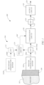
- FIG. 1 is a simplified block diagram of an industrial temperature transmitter, generally referred to as 100, formed in accordance with one or more embodiments of the present disclosure, interacting with a process medium 102.
- the process medium 102 includes an industrial process that involves a material, such as a fluid, moving through pipes and tanks to transform less valuable materials into more valuable and useful products, such as petroleum, chemicals, paper, food, etc.
- a material such as a fluid
- an oil refinery performs industrial processes that can process crude oil into gasoline, fuel oil, and other petrochemicals.
- Industrial process control systems use process devices, such as process transmitters, as measurement instruments for sensing and measuring process parameters, such as pressure, flow, temperature, level, and other parameters, in combination with, for example, control devices, such as valves, pumps and motors, to control the flow of materials during their processing.
- process devices such as process transmitters
- measurement instruments for sensing and measuring process parameters, such as pressure, flow, temperature, level, and other parameters, in combination with, for example, control devices, such as valves, pumps and motors, to control the flow of materials during their processing.
- the temperature transmitter 100 includes a temperature sensing unit 104 that is configured to sense a temperature of the process medium 102 and output a measured temperature signal, generally referred to as 106, that is indicative of the temperature of the process medium 102.
- the unit 104 includes one or more temperature sensors, generally referred to as 105, that are used to measure a temperature of the process medium 102.
- the one or more temperature sensors 105 may take on any suitable form.
- the sensors 105 may each include a thermocouple, a resistive temperature detector, a thermistor, and/or another suitable temperature sensing device.
- the unit 104 includes at least one process temperature sensor 105A (hereinafter "temperature sensor 105A”) that is separated from the process medium 102 by an isolation wall 108 that engages the process medium 102 and isolates the sensor 105A from the process medium 102.
- the isolation wall 108 is a wall of a process vessel (e.g., a pipe, a tank, etc.) containing the process medium 102, for example.
- the isolation wall 108 is a sheath or wall of the temperature sensor 105A or other housing.
- the sensor 105A is configured to produce a temperature signal 106A that is a function of the temperature of the process medium 102 that is communicated through the wall 108.
- the temperature signal 106 is produced by the unit 104 using only the temperature signal 106A produced by the one or more process temperature sensors 105A, such as when the temperature transmitter 100 uses a thermowell, as discussed below.
- temperature sensing unit 104 includes one or more secondary temperature sensors 105B (hereinafter “secondary temperature sensor 105B”) and a processing circuit 110, which are illustrated in phantom lines.
- the processing circuit 110 may comprise analog circuitry and/or digital circuitry.
- the processing circuit 110 represents one or more processors that are configured to execute instructions, which may be stored locally in memory of the processing circuit 110, or in memory that is remote to the transmitter 100, to perform one or more functions described herein.
- the temperature sensor 105B is configured to output a temperature signal 106B that is processed along with the temperature signal 106A by the processing circuit 110 to estimate the temperature of the process medium 102.
- the temperature signal 106B may be indicative of the ambient conditions to which the isolation wall 108 and/or another component of the transmitter 100 is exposed.
- the processing circuit 110 processes the temperature signals 106A and 106B to produce the temperature signal 106 representing the temperature measured by the unit 104.
- the secondary temperature sensor 105B and the processing circuit 110 are used with non-intrusive temperature transmitters 100, as discussed below.
- the transmitter 100 is an analog device, in which the temperature signals 106, 106A, and/or 106B (if present) are analog signals.
- the temperature transmitter 100 includes one or more analog-to-digital converters (ADC) 112 that digitizes the analog temperature signals into a digital temperature signal (e.g., 106', 106A', 106B') for processing by circuitry of the transmitter in the digital domain, as illustrated in FIG. 1 .
- ADC analog-to-digital converters
- separate ADC's 112 are used, as shown in FIG. 1 .
- a single ADC 112 may be used with the input signals (e.g., 106A and 106B) multiplexed into it.
- the communication of the temperature of the process medium 102 through the isolation wall 108 delays the communication of a temperature change in the medium 102 to the temperature sensor 105A. As a result, a period of time must elapse before the temperature change of the medium 102 is measured by the sensor 105A and the measured temperature represented by the temperature signal 106 indicates the temperature change.
- This delay in the temperature measurement corresponds to a response time of the temperature measurement, which may be dependent on one or more variables, such as the material forming the isolation wall 108, the thickness of the isolation wall 108, the mass of the isolation wall 108, the thermal conductivity of the isolation wall 108, an ambient temperature to which the isolation wall 108 is exposed, and/or other variables.
- Effects of the delay in the temperature measurement of the process medium 102 include a limit on the measurement bandwidth.
- the delay acts as a low-pass filter whose cutoff frequency drops in response to an increase in the delay or a decrease in the response time.
- changes in the temperature of the process medium 102 occurring at a frequency that is above the cutoff frequency are rendered undetectable by the temperature sensing unit 104.
- Embodiments of the present disclosure operate to reduce or eliminate the temperature measurement delay by reducing the "perceived" response time of the temperature measurement or by reducing the impact of the response time of the temperature measurement, thereby decreasing the cutoff frequency and the loss of potentially valuable information.
- the temperature transmitter 100 includes a compensation circuit 120 that is configured to process the temperature signal 106 output by the temperature sensing unit 104 to compensate the temperature signal 106 or the temperature measurement indicated by the temperature signal 106 for the response time of the temperature measurement, and output a compensated temperature signal 122 that more accurately represents the current temperature of the process medium 102.
- the compensation circuit 120 compensates the temperature signal 106 that is produced based on the temperature signal 106A output from the process temperature sensor 105A.
- the compensation circuit 120 compensates the temperature signal 106 output by the processing circuit 110, which is based on the temperature signal 106A output from the temperature sensor 105A and the temperature signal 106B output from the temperature sensor 105B.
- FIG. 2 is a simplified block diagram illustrating exemplary signal processing performed by the compensation circuit 120.
- a step temperature change to the process medium 102 occurs at time t 0 , such as an increase from temp T 0 to temp T 1 , as indicated in the chart within the box representing the process medium 102
- a delay occurs before the temperature change is measured by the temperature sensing unit 104.
- This delay is indicated in the chart representing the temperature measurement indicated by the signal 106 that is presented in the box representing the temperature sensing unit 104.
- the response time of the temperature measurement causing the delay between the temperature indicated by the temperature signal 106 and the actual temperature of the process medium 102 is due, at least in part, to the necessity to communicate the temperature change through the isolation wall 108.
- the compensation circuit 120 may comprise analog circuitry and/or digital circuitry.
- the compensation circuit 120 represents one or more processors that are configured to execute instructions, which may be stored locally in memory of the compensation circuit 120, or in memory that is remote to the transmitter 100, to perform one or more functions described herein.
- the compensated temperature signal 122 is a digital signal
- the temperature transmitter 100 includes a digital-to-analog converter (DAC) 124 that converts the compensated temperature signal 122 to an analog compensated temperature signal 122'.
- DAC digital-to-analog converter
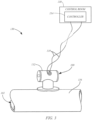
- FIG. 3 is a simplified diagram showing an exemplary industrial process control system 130 including the temperature transmitter 100 formed in accordance with one or more embodiments described herein.
- the transmitter 100 includes a housing 132 that may contain, for example, the compensation circuit 120, the output circuit 126, and/or other components of the transmitter described herein.
- the output circuit 126 is configured to transmit the temperature output 128 to a suitable controller 134 that uses the temperature output 128 to control aspects of the process medium 102, such as a process fluid flowing through a process vessel 136, such as a pipe.
- the controller 134 is located remotely from the temperature transmitter 100, such as in a remote control room 138, as shown in FIG. 3 .
- the output circuit 126 is connected to the controller 134 over a two-wire loop 139, as illustrated in FIG. 3 .
- the two-wire loop 139 is configured to transmit all electrical power required by the temperature transmitter 100 to operate.
- the output circuit 126 communicates the temperature output 128 over the two-wire loop 139 to the controller 134 by modulating a current flow that varies between 4-20 milliamps.
- the output circuit 126 may be configured to transmit the temperature output 128 to the controller 134 wirelessly in a point-to-point configuration, a mesh network, or other suitable configuration with the temperature transmitter 100 having its own power source.
- FIG. 4 is simplified cross-sectional view of a portion of a temperature sensing unit 104 within a thermowell 140 of a temperature transmitter 100, which is not forming part of the invention.
- the thermowell 140 includes the isolation wall 108 and encloses the temperature sensor 105A.
- the thermowell 140 extends through a wall 142 of a process vessel 136, such as a process pipe (shown), a tank, or other process vessel, to position the thermowell 140 within the process medium 102.
- the temperature sensor 105A is located at a distal end of a sensor probe 146, which positions the temperature sensor 105A within a temperature sensing region 148 of the thermowell 140.
- a temperature transmitter is disclosed in U.S. Patent No. 9,188,490 .
- the isolation wall 108 of the thermowell 140 isolates the temperature sensor 104 from the process medium 102.
- the isolation wall 108 is a cylindrical or conical wall that surrounds the temperature sensor 105A.
- the isolation wall 108 is formed of a highly thermally conductive material, such as brass, steel, copper, or other suitably thermally conductive material. Such materials reduce the time required to communicate (i.e., conduct) the temperature of the medium 102 to the sensor 105A.
- the temperature signal 108 ( FIG. 1 ) output by the temperature sensor 104 may be communicated to other components of the transmitter 100, such as the compensation circuit 110 through wires 149, for example.
- FIG. 5 is a diagrammatic view of a temperature sensing unit 104 of an exemplary non-intrusive temperature transmitter 100 that is located externally to the process vessel 136 (e.g., pipe, tank, etc.), in accordance with embodiments of the present disclosure.
- exemplary non-intrusive temperature transmitter is disclosed in U.S. Publication No. 2015/0185085 .
- the wall 142 of the process vessel 136 forms the isolation wall 108 that separates the process medium 102 from the temperature sensor 105A (Tsensor), which is placed in contact with or in close proximity to the exterior surface 144 of the wall 142, as shown in FIG. 5 .
- the process temperature sensor 105A performs a temperature measurement of the process medium 102 through the wall 142, which is illustrated as a pipe in FIG. 5 , by measuring a temperature at the exterior surface 144.
- Heat flow is modeled in FIG. 5 in terms of electrical components.
- the temperature of the process fluid is illustrated as node 150 and is coupled to the temperature sensor 105A via the thermal impedance (Rpipe) of the pipe 136 or wall 142 indicated diagrammatically as a resistor 154.
- the thermal impedance of the pipe 136 or wall 142 can be known either by virtue of the material of the pipe 136 itself and the thickness of the pipe wall 142 such that a suitable impedance parameter could be entered into circuitry of the unit 104, such as the compensation circuit 120.
- a user configuring the system may indicate that the pipe 136 is constructed from stainless steel and the wall 142 is 1.27 cm (1/2 inch) thick.
- suitable lookup data within memory can be accessed by the compensation circuit 120 to identify a corresponding thermal impedance that matches the selected material and wall thickness.
- embodiments may be practiced where the pipe material is simply selected and the thermal impedance can be calculated based on the selected material and the selected wall thickness. Regardless, embodiments of the present disclosure generally leverage knowledge of the thermal impedance of the pipe material. Further, in embodiments where the thermal impedance of the pipe material cannot be known ahead of time, it is also possible that a calibration operation can be provided where a known process fluid temperature is provided to the non-invasive process fluid temperature calculation system and the thermal impedance is set as a calibration parameter.
- heat may also flow from the temperature sensor 105A out the sidewall of stem portion 154 to the ambient environment illustrated at reference numeral 156.
- This is illustrated diagrammatically as thermal impedance (R2) at reference number 158.
- the thermal impedance (R2) to the ambient environment can be increased by thermally insulating the temperature sensor 105A.
- Heat also flows from the external surface 144 of the pipe 136 through the stem portion 154 to a housing 159 or other location that is spaced from the pipe 136 via conduction through stem portion 154.
- the housing 159 encloses circuitry of the temperature sensing unit 104, such as the compensation circuit 120 and the output circuit 126, for example.
- the thermal impedance of the stem portion 154 (Rsensor) is illustrated diagrammatically at reference numeral 160.
- the temperature sensing unit 104 includes a temperature sensor 105B (Tterm) that is coupled to a terminal block or other location within the housing 159 to measure the terminal temperature. Heat may flow from the temperature sensor 105B to the ambient environment via thermal impedance 164 (R1).
- T corrected T sensor + T sensor ⁇ T terminal * R pipe / R sensor .
- embodiments of the compensation circuit 120 operate to compensate the corrected temperature (Tcorrected) indicated by the temperature signal 106 or 106', for the response time of the temperature measurement, such as the time required to communicate the temperature of the process medium 102 through the isolation wall 108 in form of the wall 142 of the pipe 136, as well as other materials, such as a sensor sheath or other material of the sensor 105A, for example.
- This can generally be approximated using the following first order equation, in which t is the update rate (e.g., 1 second or less) of the temperature measurement (Tcorrected), and ⁇ is the time constant of the components involved in the temperature measurement.
- Temp meas Temp process ⁇ 1 ⁇ e ⁇ t ⁇
- the compensation circuit 120 applies dynamic compensation to the temperature measurement by knowing the time constant and trend information about the temperature measurement.
- the rate of change of the measurement can be evaluated over a number of samples to provide a percentage and direction of correction that minimizes sampling noise.
- the rate of change can be divided by the exponential portion of Equation 1 to provide the dynamic compensation to the measured temperature, as indicated in Equation 2.
- Temp dynamicComp Temp meas _ ROC 1 ⁇ e ⁇ t ⁇
- a compensated temperature measurement value (Temp measCompensated ), which is represented by the compensated temperature signal 122 ( FIG. 1 ), is calculated by adding the measured temperature value (Temp meas ) corresponding to the signal 106 or 106' from the sensing unit 104 with the dynamic compensation value (Temp dynamicComp ), as indicated in Equation 3.
- the time delay described above between the measured temperature (Temp meas ) and the current temperature of the medium 102 is removed or significantly reduced in the compensated temperature measurement (Temp measCompensated ), as indicated by the signal 122 in FIG. 2 .
- Temp measCompensated Temp meas + Temp dynamicComp
- FIG. 6 is a graph illustrating the amount of correction that should be applied to a temperature measurement in relation to the measurement rate of change for a stepped input from 60°C to 120°C with a 3-minute time constant. As shown in FIG. 6 , as the trending change in the temperature measurement is smaller, so is the necessary correction (Temp dynamicComp ).
- parameters of the process vessel wall 142 which forms the isolation wall 108, must be known, such as the material forming the wall 142, thickness of the wall 142, and/or other parameters of the process vessel wall 142. These can be set in the transmitter 100.
- parameters of the process vessel wall 142 are used to determine the time constant for the specific process vessel wall 142, through which the transmitter 100 is measuring the temperature of the process medium 102. Testing has shown that the time constant for each supported pipe material can be approximated using a linear equation for any pipe wall thickness. For example, the time constant in minutes for carbon steel can be calculated using Equation 4 below.
- ⁇ cs 8.042 ⁇ Wall thickness + 1.031
- Time constants for transmitters 100 utilizing a thermowell can be calculated in a similar manner to determine the amount of correction (Temp dynamicComp ) of the measured temperature (Temp meas ) that is required.
- Adjustments to calculated time constants can be made if additional information is supplied, such as the type of process medium contained within the process vessel 136, the density of the process medium 102, and/or other information.
- embodiments of the present disclosure may be applied to compensate for delays in the response time of other types of temperature sensors.
- the response time of a resistance temperature detector (RTD) used for cold junction compensation of a thermocouple may be compensated for using the techniques described above, such as when the ambient temperature changes quickly.
- RTD's have slower response times than thermocouples
- embodiments of the present disclosure may be used to speed up measurements performed by an RTD having an isolation wall in the form of an exterior wall of the RTD, for example.
- parameter values such as time constants, wall thicknesses, and/or other information used by the compensation circuit 120, may be stored in memory that is accessible by the compensation circuit 120.
- the parameter values are stored in one or more radio frequency identification (RFID's) tags.
- RFID tags are attached to the temperature sensor being compensated, the isolation wall (e.g., thermowell or process vessel), or other component.
Landscapes
- Physics & Mathematics (AREA)
- General Physics & Mathematics (AREA)
- Nonlinear Science (AREA)
- Arrangements For Transmission Of Measured Signals (AREA)
- Measuring Temperature Or Quantity Of Heat (AREA)
Claims (12)
- Temperatursender (100) für industrielle Prozesse zum Messen einer Temperatur eines Prozessmediums (102), das in einem Prozessbehälter (136) enthalten ist, der eine Isolationswand (108) umfasst, wobei der Temperatursender (100) für industrielle Prozesse umfasst:einen wärmeleitfähigen Schaftabschnitt (154), der ein erstes Ende aufweist, das dazu eingerichtet ist, in Kontakt mit der, oder in unmittelbare Nähe zu der, Isolationswand (108) gebracht zu werden, und ein zweites Ende aufweist; undein Gehäuse (159), das an dem zweiten Ende des Schaftabschnitts (154) angebracht ist;einen Prozesstemperatursensor (105A), der dazu eingerichtet ist, eine Temperaturmessung des Prozessmediums (102) durch die Isolationswand (108) hindurch durchzuführen;einen sekundären Temperatursensor (105B), der dazu eingerichtet ist, ein sekundäres Temperatursignal (106B) auf der Grundlage einer abgefühlten Temperatur zu erzeugen, wobei sich der sekundäre Temperatursensor (105B) innerhalb des Gehäuses (159) befindet;wobei der Temperatursender (100) für industrielle Prozesse dazu eingerichtet ist, ein Temperatursignal (106'), das die Temperatur des Prozessmediums (102) in dem Prozessbehälter (136) angibt, auf der Grundlage eines von dem Prozesstemperatursensor (105A) ausgegebenen Prozesstemperatursignal (106A) und des sekundären Temperatursignals (106B) während einer Temperaturmessung zu erzeugen;eine Kompensationsschaltung (120), die dazu eingerichtet ist, das Temperatursignal (106') um eine Ansprechzeit der Temperaturmessung auf eine Änderung der Temperatur des Prozessmediums (102) und eine Änderungsrate der Temperaturmessung dynamisch zu kompensieren und ein kompensiertes Temperatursignal (122, 122') auszugeben;eine Ausgabeschaltung (126), die dazu eingerichtet ist, eine Temperaturausgabe (128) als eine Funktion des kompensierten Temperatursignals (122, 122') zu erzeugen.
- Sender nach Anspruch 1, wobei:die Ansprechzeit der Temperaturmessung von mindestens einer Eigenschaft der Isolationswand (108) abhängig ist, die ausgewählt ist aus der Gruppe bestehend aus einer Masse der Isolationswand (108), einer Wärmeleitfähigkeit der Isolationswand (108), und einer Dicke der Isolationswand (108); unddie Kompensationsschaltung (120) das Temperatursignal (106') auf der Grundlage der mindestens einen Eigenschaft der Isolationswand (108) kompensiert und das kompensierte Temperatursignal (122, 122') ausgibt.
- Sender nach Anspruch 1, wobei:die Isolationswand (108) eine Wand des Prozessbehälters (136) bildet;der Prozesstemperatursensor (105A) dazu eingerichtet ist, in thermischen Kontakt mit einer Außenfläche (144) der Isolationswand (108) gebracht zu werden; undder sekundäre Temperatursensor (105B) dazu eingerichtet ist, über den wärmeleitfähigen Schaftabschnitt (154) in thermischen Kontakt mit einer Außenfläche (144) der Isolationswand (108) gebracht zu werden.
- Sender nach Anspruch 3, wobei der Prozessbehälter (136) ausgewählt ist aus der Gruppe bestehend aus einem Rohr (136) und einem Tank, oder wobei der sekundäre Temperatursensor (105B) eine Anschlussblocktemperatur des innerhalb des Gehäuses (159) befindlichen Senders (100) misst.
- Sender nach Anspruch 3, wobei:der Temperatursender (100) für industrielle Prozesse mindestens einen Analog-Digital-Wandler (112) aufweist, der dazu eingerichtet ist, das Prozesstemperatursignal (106A) in einer analogen Form in ein digitales Prozesstemperatursignal (106A') umzuwandeln und das sekundäre Temperatursignal (106B) in einer analogen Form in ein digitales sekundäres Temperatursignal (106B') umzuwandeln;eine Verarbeitungsschaltung (110) das Temperatursignal (106') in einer digitalen Form auf der Grundlage des digitalen Prozesstemperatursignals (106A') und des digitalen sekundären Temperatursignals (106B') erzeugt;ein Digital-Analog-Wandler (124) dazu eingerichtet ist, das kompensierte Temperatursignal (122) in einer digitalen Form in ein analoges kompensiertes Temperatursignal (122') umzuwandeln;wobei die Ausgabeschaltung (126) dazu eingerichtet ist, die Temperaturausgabe (128) als eine Funktion des analogen kompensierten Temperatursignals (122') zu erzeugen.
- Sender nach Anspruch 1, wobei:der Temperatursender (100) für industrielle Prozesse einen Analog-Digital-Wandler (112) aufweist, der dazu eingerichtet ist, das Prozesstemperatursignal (106A) in einer analogen Form in ein digitales Prozesstemperatursignal (106A') umzuwandeln, um das Temperatursignal (106') in einer digitalen Form zu erzeugen; undein Digital-Analog-Wandler (124) dazu eingerichtet ist, das kompensierte Temperatursignal (122) in einer digitalen Form in ein analoges kompensiertes Temperatursignal (122') umzuwandeln;wobei die Ausgabeschaltung (126) dazu eingerichtet ist, die Temperaturausgabe (128) als eine Funktion des analogen kompensierten Temperatursignals (122') zu erzeugen.
- Sender nach Anspruch 1, wobei:die Ansprechzeit der Temperaturmessung von mindestens einer Eigenschaft der Isolationswand (108) abhängig ist, die ausgewählt ist aus der Gruppe bestehend aus einer Masse der Isolationswand (108), einer Wärmeleitfähigkeit der Isolationswand (108), und einer Dicke der Isolationswand (108); unddie Kompensationsschaltung (120) dazu eingerichtet ist, das Temperatursignal (106') zu kompensieren und das kompensierte Temperatursignal (122, 122') auf der Grundlage der mindestens einen Eigenschaft der Isolationswand (108) zu erzeugen.
- Sender nach Anspruch 7, wobei der Prozessbehälter (136) ausgewählt ist aus der Gruppe bestehend aus einem Rohr (136) und einem Tank, oder wobei die Kompensationsschaltung (120) dazu eingerichtet ist, das Temperatursignal (106') um die Ansprechzeit der Temperaturmessung auf der Grundlage einer thermischen Impedanz des Schaftabschnitts (154) zu kompensieren.
- Sender nach Anspruch 7, wobei:der Temperatursender (100) für industrielle Prozesse einen ersten Analog-Digital-Wandler (112) aufweist, der dazu eingerichtet ist, das Prozesstemperatursignal (106A) in einer analogen Form in ein digitales Prozesstemperatursignal (106A') umzuwandeln, und einen zweiten Analog-Digital-Wandler (112) aufweist, der dazu eingerichtet ist, das sekundäre Temperatursignal (106B) in einer analogen Form in ein digitales sekundäre Temperatursignal (106B') umzuwandeln;die Verarbeitungsschaltung (110) das Temperatursignal (106') in einer digitalen Form auf der Grundlage des digitalen Prozesstemperatursignals (106A') und des digitalen sekundären Temperatursignals (106B') erzeugt; undein Digital-Analog-Wandler (124) dazu eingerichtet ist, das kompensierte Temperatursignal (122) in einer digitalen Form in ein analoges kompensiertes Temperatursignal (122') umzuwandeln;wobei die Ausgabeschaltung (126) dazu eingerichtet ist, die Temperaturausgabe (128) als eine Funktion des analogen kompensierten Temperatursignals (122') zu erzeugen.
- Verfahren zum Messen einer Temperatur eines Prozessmediums (102), das in einem Prozessbehälter (136) enthalten ist, unter Verwendung eines Temperatursenders (100) für industrielle Prozesse, der ein Gehäuse (159) umfasst, wobei das Verfahren umfasst:
Durchführen einer Temperaturmessung der Temperatur eines Prozessmediums (102) unter Verwendung des Temperatursenders (100) für industrielle Prozesse, was umfasst:Abfühlen der Temperatur des Prozessmediums (102) durch eine Isolationswand (108) des Prozessbehälters (136) unter Verwendung eines Prozesstemperatursensors (105A), der einen Thermistor umfasst;Erfassen einer Temperatur eines Anschlussblocks oder einer anderen Stelle innerhalb des Gehäuses (159), die thermisch mit dem Prozessmedium (102) verbunden und mittels eines wärmeleitfähigen Schaftabschnitts (154) von dem Prozessmedium (102) beabstandet ist, unter Verwendung eines sekundären Temperatursensors (105B);Erzeugen eines Temperatursignals (106') in Reaktion auf die Temperaturmessung, umfassend das Verarbeiten eines Temperatursignals (106A) von dem Prozesstemperatursensor (105A) und eines sekundären Temperatursignals (106B) von dem sekundären Temperatursensor (105B);dynamisches Kompensieren des Temperatursignals (106') um eine Ansprechzeit der Temperaturmessung und eine Änderungsrate der Temperaturmessung unter Verwendung einer Kompensationsschaltung (120);Erzeugen eines kompensierten Temperatursignals (122, 122'), in dem die Ansprechzeit der Temperaturmessung reduziert oder eliminiert ist, unter Verwendung der Kompensationsschaltung (120); undErzeugen einer Temperaturausgabe (128) als eine Funktion des kompensierten Temperatursignals (122, 122') unter Verwendung einer Ausgabeschaltung (126). - Verfahren nach Anspruch 10, wobei das Kompensieren des Temperatursignals (106') das Kompensieren des Temperatursignals (106') auf der Grundlage mindestens einer Eigenschaft der Isolationswand umfasst, die ausgewählt ist aus der Gruppe bestehend aus einer Masse der Isolationswand (108), einer Wärmeleitfähigkeit der Isolationswand (108), und einer Dicke der Isolationswand (108).
- Verfahren nach Anspruch 10, wobei:
das Durchführen einer Temperaturmessung das Inkontaktbringen einer Außenfläche (144) der Isolationswand (108) mit dem Prozesstemperatursensor (105A) umfasst.
Applications Claiming Priority (2)
| Application Number | Priority Date | Filing Date | Title |
|---|---|---|---|
| US15/437,731 US20180238741A1 (en) | 2017-02-21 | 2017-02-21 | Process transmitter isolation compensation |
| PCT/US2018/017937 WO2018156383A1 (en) | 2017-02-21 | 2018-02-13 | Process transmitter isolation compensation |
Publications (2)
| Publication Number | Publication Date |
|---|---|
| EP3586095A1 EP3586095A1 (de) | 2020-01-01 |
| EP3586095B1 true EP3586095B1 (de) | 2025-04-23 |
Family
ID=61283363
Family Applications (1)
| Application Number | Title | Priority Date | Filing Date |
|---|---|---|---|
| EP18707531.2A Active EP3586095B1 (de) | 2017-02-21 | 2018-02-13 | Ansprechzeitkompensation für einen temperaturtransmitter für industrielle verfahren |
Country Status (9)
| Country | Link |
|---|---|
| US (1) | US20180238741A1 (de) |
| EP (1) | EP3586095B1 (de) |
| JP (1) | JP7007035B2 (de) |
| CN (3) | CN108458798A (de) |
| AU (1) | AU2018224018B2 (de) |
| CA (1) | CA3053768C (de) |
| MX (1) | MX2019010017A (de) |
| RU (1) | RU2723067C1 (de) |
| WO (1) | WO2018156383A1 (de) |
Families Citing this family (12)
| Publication number | Priority date | Publication date | Assignee | Title |
|---|---|---|---|---|
| US20180238741A1 (en) * | 2017-02-21 | 2018-08-23 | Rosemount Inc. | Process transmitter isolation compensation |
| US11226242B2 (en) | 2016-01-25 | 2022-01-18 | Rosemount Inc. | Process transmitter isolation compensation |
| US11226255B2 (en) | 2016-09-29 | 2022-01-18 | Rosemount Inc. | Process transmitter isolation unit compensation |
| US10842950B2 (en) | 2017-08-15 | 2020-11-24 | Biosense Webster (Israel) Ltd. | Detection of bubbles in irrigation fluid |
| EP3857189B1 (de) | 2018-09-28 | 2025-01-15 | Rosemount Inc. | Nichtinvasive prozessflüssigkeitstemperaturanzeige mit reduzierter fehleranfälligkeit |
| US20200103293A1 (en) * | 2018-09-28 | 2020-04-02 | Rosemount Inc. | Non-invasive process fluid temperature indication |
| US20210396560A1 (en) * | 2020-06-17 | 2021-12-23 | Rosemount Inc | Subsea multivariable transmitter |
| WO2022272021A1 (en) | 2021-06-25 | 2022-12-29 | Rosemount Inc. | Heat flow-based process fluid temperature estimation system with thermal time response improvement |
| US12072245B2 (en) * | 2021-09-30 | 2024-08-27 | Rosemount Inc. | Heat flux temperature sensor probe for non-invasive process fluid temperature applications |
| CN115307768B (zh) * | 2022-07-27 | 2024-05-24 | 深圳安吉尔饮水产业集团有限公司 | 一种ntc检测时间补偿算法 |
| EP4336158A1 (de) * | 2022-09-06 | 2024-03-13 | Siemens Aktiengesellschaft | Temperaturmesseinrichtung |
| CN120760872B (zh) * | 2025-09-08 | 2025-11-21 | 国网浙江省电力有限公司杭州市萧山区供电公司 | 一种温度传感与射频识别电路集成测温方法及系统 |
Family Cites Families (24)
| Publication number | Priority date | Publication date | Assignee | Title |
|---|---|---|---|---|
| JPS5814718B2 (ja) * | 1976-04-08 | 1983-03-22 | 日産自動車株式会社 | 応答遅れ補償回路 |
| DE3803104A1 (de) * | 1988-02-03 | 1989-08-17 | Vdo Schindling | Schaltungsanordnung zur korrektur schwacher analoger spannungen von messwertgebern bei starker nichtlinearitaet |
| JPH04357426A (ja) * | 1991-06-04 | 1992-12-10 | Furuno Electric Co Ltd | 温度計 |
| DE4120388C2 (de) * | 1991-06-19 | 2001-05-03 | Bosch Gmbh Robert | Verfahren zur Temperaturerfassung |
| JPH06249715A (ja) * | 1993-03-01 | 1994-09-09 | Sumitomo Heavy Ind Ltd | 溶融金属の間欠的温度測定方法 |
| US6390670B1 (en) * | 1999-08-06 | 2002-05-21 | Pgi International Ltd. | Temperature sensing device for metering fluids |
| DE19939757A1 (de) * | 1999-08-21 | 2001-02-22 | Temperaturmestechnik Geraberg | Verfahren und Temperaturfühler zur Medientemperaturerfassung |
| JP4300406B2 (ja) * | 2003-03-18 | 2009-07-22 | 横河電機株式会社 | 基準接点温度測定装置 |
| US7447607B2 (en) * | 2004-08-31 | 2008-11-04 | Watow Electric Manufacturing | System and method of compensation for device mounting and thermal transfer error |
| DE102007055029A1 (de) * | 2007-11-17 | 2009-08-06 | Stiebel Eltron Gmbh & Co. Kg | Verfahren zur Kompensation einer Übertragungsfunktion einer Messwerterfassung |
| US9157763B2 (en) * | 2008-02-06 | 2015-10-13 | Rosemount, Inc. | Minimal dead time digitally compensated process transmitter |
| UA37415U (uk) * | 2008-06-19 | 2008-11-25 | Володимир Миколайович Буценко | Процес для передвіщення відповіді датчика параметра |
| FR2939508B1 (fr) * | 2008-12-09 | 2011-01-07 | Snecma | Procede et systeme de correction d'un signal de mesure d'une temperature. |
| JP2011027619A (ja) * | 2009-07-28 | 2011-02-10 | Toyama Sangyo Kk | 温度測定システム及び温度測定方法、並びに、これらを用いた溶出試験器の温度制御システム及び温度制御方法 |
| US8301408B2 (en) * | 2010-03-09 | 2012-10-30 | Invensys Systems, Inc. | Temperature prediction transmitter |
| US8308349B1 (en) * | 2010-11-08 | 2012-11-13 | Murray F Feller | Asymmetric heat flux sensor with in-situ drift compensation |
| US20130032538A1 (en) * | 2011-08-01 | 2013-02-07 | Nrgtek, Inc | Systems and methods for forward osmosis fluid purification |
| US8767193B2 (en) * | 2012-07-10 | 2014-07-01 | Raytheon Company | Doppler tracking in presence of vehicle velocity uncertainty |
| US9188490B2 (en) | 2013-03-12 | 2015-11-17 | Rosemount Inc. | Thermowell insert |
| US9360377B2 (en) | 2013-12-26 | 2016-06-07 | Rosemount Inc. | Non-intrusive temperature measurement assembly |
| US9488527B2 (en) * | 2014-03-25 | 2016-11-08 | Rosemount Inc. | Process temperature measurement using infrared detector |
| DE102014019365B4 (de) * | 2014-12-22 | 2021-02-18 | Abb Schweiz Ag | Vorrichtung zur Messung der Temperatur eines Mediums durch eine Wandung |
| US20180238741A1 (en) * | 2017-02-21 | 2018-08-23 | Rosemount Inc. | Process transmitter isolation compensation |
| CN105716733B (zh) * | 2016-01-29 | 2018-07-17 | 东南大学 | 一种火电机组套管式热电偶温度测量的动态校正方法 |
-
2017
- 2017-02-21 US US15/437,731 patent/US20180238741A1/en not_active Abandoned
- 2017-05-26 CN CN201710387443.4A patent/CN108458798A/zh active Pending
- 2017-05-26 CN CN202410957930.XA patent/CN118896699A/zh active Pending
- 2017-05-26 CN CN201720603454.7U patent/CN206905923U/zh active Active
-
2018
- 2018-02-13 MX MX2019010017A patent/MX2019010017A/es unknown
- 2018-02-13 WO PCT/US2018/017937 patent/WO2018156383A1/en not_active Ceased
- 2018-02-13 EP EP18707531.2A patent/EP3586095B1/de active Active
- 2018-02-13 AU AU2018224018A patent/AU2018224018B2/en active Active
- 2018-02-13 RU RU2019129543A patent/RU2723067C1/ru active
- 2018-02-13 JP JP2019566568A patent/JP7007035B2/ja active Active
- 2018-02-13 CA CA3053768A patent/CA3053768C/en active Active
Also Published As
| Publication number | Publication date |
|---|---|
| US20180238741A1 (en) | 2018-08-23 |
| CN108458798A (zh) | 2018-08-28 |
| MX2019010017A (es) | 2019-11-21 |
| AU2018224018B2 (en) | 2021-04-08 |
| CA3053768C (en) | 2023-03-21 |
| WO2018156383A1 (en) | 2018-08-30 |
| CN118896699A (zh) | 2024-11-05 |
| JP7007035B2 (ja) | 2022-01-24 |
| EP3586095A1 (de) | 2020-01-01 |
| JP2020508474A (ja) | 2020-03-19 |
| CN206905923U (zh) | 2018-01-19 |
| RU2723067C1 (ru) | 2020-06-08 |
| CA3053768A1 (en) | 2018-08-30 |
| AU2018224018A1 (en) | 2019-09-05 |
Similar Documents
| Publication | Publication Date | Title |
|---|---|---|
| EP3586095B1 (de) | Ansprechzeitkompensation für einen temperaturtransmitter für industrielle verfahren | |
| CN112595427B (zh) | 非侵入式过程流体温度计算系统 | |
| CN112771357B (zh) | 减少误差的非侵入式过程流体温度指示 | |
| JP2022501598A (ja) | 高温用途向けの非侵襲的プロセス流体温度表示 | |
| CN108458792B (zh) | 具有冷接合点补偿的热电偶温度传感器 | |
| EP3494378B1 (de) | Prozessemitterisolierungseinheitenkompensation | |
| US11226242B2 (en) | Process transmitter isolation compensation | |
| JP7708896B2 (ja) | 熱時間応答を改善した熱流ベースのプロセス流体温度推定システム |
Legal Events
| Date | Code | Title | Description |
|---|---|---|---|
| STAA | Information on the status of an ep patent application or granted ep patent |
Free format text: STATUS: UNKNOWN |
|
| STAA | Information on the status of an ep patent application or granted ep patent |
Free format text: STATUS: THE INTERNATIONAL PUBLICATION HAS BEEN MADE |
|
| PUAI | Public reference made under article 153(3) epc to a published international application that has entered the european phase |
Free format text: ORIGINAL CODE: 0009012 |
|
| STAA | Information on the status of an ep patent application or granted ep patent |
Free format text: STATUS: REQUEST FOR EXAMINATION WAS MADE |
|
| 17P | Request for examination filed |
Effective date: 20190920 |
|
| AK | Designated contracting states |
Kind code of ref document: A1 Designated state(s): AL AT BE BG CH CY CZ DE DK EE ES FI FR GB GR HR HU IE IS IT LI LT LU LV MC MK MT NL NO PL PT RO RS SE SI SK SM TR |
|
| AX | Request for extension of the european patent |
Extension state: BA ME |
|
| DAV | Request for validation of the european patent (deleted) | ||
| DAX | Request for extension of the european patent (deleted) | ||
| STAA | Information on the status of an ep patent application or granted ep patent |
Free format text: STATUS: EXAMINATION IS IN PROGRESS |
|
| 17Q | First examination report despatched |
Effective date: 20211108 |
|
| REG | Reference to a national code |
Ref country code: DE Ref legal event code: R079 Free format text: PREVIOUS MAIN CLASS: G01K0001140000 Ipc: G01K0001143000 Ref country code: DE Ref legal event code: R079 Ref document number: 602018081274 Country of ref document: DE Free format text: PREVIOUS MAIN CLASS: G01K0001140000 Ipc: G01K0001143000 |
|
| GRAP | Despatch of communication of intention to grant a patent |
Free format text: ORIGINAL CODE: EPIDOSNIGR1 |
|
| STAA | Information on the status of an ep patent application or granted ep patent |
Free format text: STATUS: GRANT OF PATENT IS INTENDED |
|
| RIC1 | Information provided on ipc code assigned before grant |
Ipc: G01K 7/42 20060101ALI20231120BHEP Ipc: G01K 1/143 20210101AFI20231120BHEP |
|
| INTG | Intention to grant announced |
Effective date: 20231213 |
|
| GRAJ | Information related to disapproval of communication of intention to grant by the applicant or resumption of examination proceedings by the epo deleted |
Free format text: ORIGINAL CODE: EPIDOSDIGR1 |
|
| STAA | Information on the status of an ep patent application or granted ep patent |
Free format text: STATUS: EXAMINATION IS IN PROGRESS |
|
| INTC | Intention to grant announced (deleted) | ||
| GRAP | Despatch of communication of intention to grant a patent |
Free format text: ORIGINAL CODE: EPIDOSNIGR1 |
|
| STAA | Information on the status of an ep patent application or granted ep patent |
Free format text: STATUS: GRANT OF PATENT IS INTENDED |
|
| INTG | Intention to grant announced |
Effective date: 20241211 |
|
| GRAS | Grant fee paid |
Free format text: ORIGINAL CODE: EPIDOSNIGR3 |
|
| GRAA | (expected) grant |
Free format text: ORIGINAL CODE: 0009210 |
|
| STAA | Information on the status of an ep patent application or granted ep patent |
Free format text: STATUS: THE PATENT HAS BEEN GRANTED |
|
| AK | Designated contracting states |
Kind code of ref document: B1 Designated state(s): AL AT BE BG CH CY CZ DE DK EE ES FI FR GB GR HR HU IE IS IT LI LT LU LV MC MK MT NL NO PL PT RO RS SE SI SK SM TR |
|
| REG | Reference to a national code |
Ref country code: GB Ref legal event code: FG4D |
|
| REG | Reference to a national code |
Ref country code: CH Ref legal event code: EP |
|
| REG | Reference to a national code |
Ref country code: DE Ref legal event code: R096 Ref document number: 602018081274 Country of ref document: DE |
|
| REG | Reference to a national code |
Ref country code: IE Ref legal event code: FG4D |
|
| REG | Reference to a national code |
Ref country code: NL Ref legal event code: FP |
|
| REG | Reference to a national code |
Ref country code: AT Ref legal event code: MK05 Ref document number: 1788153 Country of ref document: AT Kind code of ref document: T Effective date: 20250423 |
|
| PG25 | Lapsed in a contracting state [announced via postgrant information from national office to epo] |
Ref country code: FI Free format text: LAPSE BECAUSE OF FAILURE TO SUBMIT A TRANSLATION OF THE DESCRIPTION OR TO PAY THE FEE WITHIN THE PRESCRIBED TIME-LIMIT Effective date: 20250423 Ref country code: ES Free format text: LAPSE BECAUSE OF FAILURE TO SUBMIT A TRANSLATION OF THE DESCRIPTION OR TO PAY THE FEE WITHIN THE PRESCRIBED TIME-LIMIT Effective date: 20250423 Ref country code: PT Free format text: LAPSE BECAUSE OF FAILURE TO SUBMIT A TRANSLATION OF THE DESCRIPTION OR TO PAY THE FEE WITHIN THE PRESCRIBED TIME-LIMIT Effective date: 20250825 |
|
| REG | Reference to a national code |
Ref country code: LT Ref legal event code: MG9D |
|
| PG25 | Lapsed in a contracting state [announced via postgrant information from national office to epo] |
Ref country code: NO Free format text: LAPSE BECAUSE OF FAILURE TO SUBMIT A TRANSLATION OF THE DESCRIPTION OR TO PAY THE FEE WITHIN THE PRESCRIBED TIME-LIMIT Effective date: 20250723 Ref country code: GR Free format text: LAPSE BECAUSE OF FAILURE TO SUBMIT A TRANSLATION OF THE DESCRIPTION OR TO PAY THE FEE WITHIN THE PRESCRIBED TIME-LIMIT Effective date: 20250724 |
|
| PG25 | Lapsed in a contracting state [announced via postgrant information from national office to epo] |
Ref country code: PL Free format text: LAPSE BECAUSE OF FAILURE TO SUBMIT A TRANSLATION OF THE DESCRIPTION OR TO PAY THE FEE WITHIN THE PRESCRIBED TIME-LIMIT Effective date: 20250423 |
|
| PG25 | Lapsed in a contracting state [announced via postgrant information from national office to epo] |
Ref country code: BG Free format text: LAPSE BECAUSE OF FAILURE TO SUBMIT A TRANSLATION OF THE DESCRIPTION OR TO PAY THE FEE WITHIN THE PRESCRIBED TIME-LIMIT Effective date: 20250423 |
|
| PG25 | Lapsed in a contracting state [announced via postgrant information from national office to epo] |
Ref country code: HR Free format text: LAPSE BECAUSE OF FAILURE TO SUBMIT A TRANSLATION OF THE DESCRIPTION OR TO PAY THE FEE WITHIN THE PRESCRIBED TIME-LIMIT Effective date: 20250423 |
|
| PG25 | Lapsed in a contracting state [announced via postgrant information from national office to epo] |
Ref country code: AT Free format text: LAPSE BECAUSE OF FAILURE TO SUBMIT A TRANSLATION OF THE DESCRIPTION OR TO PAY THE FEE WITHIN THE PRESCRIBED TIME-LIMIT Effective date: 20250423 |
|
| PG25 | Lapsed in a contracting state [announced via postgrant information from national office to epo] |
Ref country code: RS Free format text: LAPSE BECAUSE OF FAILURE TO SUBMIT A TRANSLATION OF THE DESCRIPTION OR TO PAY THE FEE WITHIN THE PRESCRIBED TIME-LIMIT Effective date: 20250723 |
|
| PG25 | Lapsed in a contracting state [announced via postgrant information from national office to epo] |
Ref country code: IS Free format text: LAPSE BECAUSE OF FAILURE TO SUBMIT A TRANSLATION OF THE DESCRIPTION OR TO PAY THE FEE WITHIN THE PRESCRIBED TIME-LIMIT Effective date: 20250823 |
|
| PG25 | Lapsed in a contracting state [announced via postgrant information from national office to epo] |
Ref country code: LV Free format text: LAPSE BECAUSE OF FAILURE TO SUBMIT A TRANSLATION OF THE DESCRIPTION OR TO PAY THE FEE WITHIN THE PRESCRIBED TIME-LIMIT Effective date: 20250423 |
|
| PG25 | Lapsed in a contracting state [announced via postgrant information from national office to epo] |
Ref country code: SM Free format text: LAPSE BECAUSE OF FAILURE TO SUBMIT A TRANSLATION OF THE DESCRIPTION OR TO PAY THE FEE WITHIN THE PRESCRIBED TIME-LIMIT Effective date: 20250423 Ref country code: DK Free format text: LAPSE BECAUSE OF FAILURE TO SUBMIT A TRANSLATION OF THE DESCRIPTION OR TO PAY THE FEE WITHIN THE PRESCRIBED TIME-LIMIT Effective date: 20250423 |
|
| PG25 | Lapsed in a contracting state [announced via postgrant information from national office to epo] |
Ref country code: CZ Free format text: LAPSE BECAUSE OF FAILURE TO SUBMIT A TRANSLATION OF THE DESCRIPTION OR TO PAY THE FEE WITHIN THE PRESCRIBED TIME-LIMIT Effective date: 20250423 |
|
| PG25 | Lapsed in a contracting state [announced via postgrant information from national office to epo] |
Ref country code: EE Free format text: LAPSE BECAUSE OF FAILURE TO SUBMIT A TRANSLATION OF THE DESCRIPTION OR TO PAY THE FEE WITHIN THE PRESCRIBED TIME-LIMIT Effective date: 20250423 |
|
| REG | Reference to a national code |
Ref country code: DE Ref legal event code: R097 Ref document number: 602018081274 Country of ref document: DE |
|
| PG25 | Lapsed in a contracting state [announced via postgrant information from national office to epo] |
Ref country code: RO Free format text: LAPSE BECAUSE OF FAILURE TO SUBMIT A TRANSLATION OF THE DESCRIPTION OR TO PAY THE FEE WITHIN THE PRESCRIBED TIME-LIMIT Effective date: 20250423 Ref country code: SK Free format text: LAPSE BECAUSE OF FAILURE TO SUBMIT A TRANSLATION OF THE DESCRIPTION OR TO PAY THE FEE WITHIN THE PRESCRIBED TIME-LIMIT Effective date: 20250423 |
|
| PG25 | Lapsed in a contracting state [announced via postgrant information from national office to epo] |
Ref country code: IT Free format text: LAPSE BECAUSE OF FAILURE TO SUBMIT A TRANSLATION OF THE DESCRIPTION OR TO PAY THE FEE WITHIN THE PRESCRIBED TIME-LIMIT Effective date: 20250423 |
|
| PLBE | No opposition filed within time limit |
Free format text: ORIGINAL CODE: 0009261 |
|
| STAA | Information on the status of an ep patent application or granted ep patent |
Free format text: STATUS: NO OPPOSITION FILED WITHIN TIME LIMIT |
|
| REG | Reference to a national code |
Ref country code: CH Ref legal event code: L10 Free format text: ST27 STATUS EVENT CODE: U-0-0-L10-L00 (AS PROVIDED BY THE NATIONAL OFFICE) Effective date: 20260304 |
|
| 26N | No opposition filed |
Effective date: 20260126 |
|
| PGFP | Annual fee paid to national office [announced via postgrant information from national office to epo] |
Ref country code: DE Payment date: 20260121 Year of fee payment: 9 |