EP3586024B1 - Soufflet tubulaire comprenant au moins une nervure de renforcement - Google Patents
Soufflet tubulaire comprenant au moins une nervure de renforcement Download PDFInfo
- Publication number
- EP3586024B1 EP3586024B1 EP17706748.5A EP17706748A EP3586024B1 EP 3586024 B1 EP3586024 B1 EP 3586024B1 EP 17706748 A EP17706748 A EP 17706748A EP 3586024 B1 EP3586024 B1 EP 3586024B1
- Authority
- EP
- European Patent Office
- Prior art keywords
- area
- region
- membrane
- ribs
- stiffening rib
- Prior art date
- Legal status (The legal status is an assumption and is not a legal conclusion. Google has not performed a legal analysis and makes no representation as to the accuracy of the status listed.)
- Active
Links
- 238000005096 rolling process Methods 0.000 title claims description 32
- 230000002787 reinforcement Effects 0.000 title claims description 12
- 239000012528 membrane Substances 0.000 claims description 77
- 230000007704 transition Effects 0.000 claims description 49
- 239000011230 binding agent Substances 0.000 description 40
- 239000000463 material Substances 0.000 description 25
- 230000003014 reinforcing effect Effects 0.000 description 6
- 239000004519 grease Substances 0.000 description 5
- 229920002725 thermoplastic elastomer Polymers 0.000 description 5
- 230000035508 accumulation Effects 0.000 description 4
- 238000009825 accumulation Methods 0.000 description 4
- 230000015572 biosynthetic process Effects 0.000 description 4
- 238000005452 bending Methods 0.000 description 3
- 239000000654 additive Substances 0.000 description 2
- 230000006835 compression Effects 0.000 description 2
- 238000007906 compression Methods 0.000 description 2
- 229920001971 elastomer Polymers 0.000 description 2
- 239000000806 elastomer Substances 0.000 description 2
- 238000005461 lubrication Methods 0.000 description 2
- 238000004519 manufacturing process Methods 0.000 description 2
- 239000004952 Polyamide Substances 0.000 description 1
- 239000004721 Polyphenylene oxide Substances 0.000 description 1
- 238000009792 diffusion process Methods 0.000 description 1
- 238000009826 distribution Methods 0.000 description 1
- 239000013536 elastomeric material Substances 0.000 description 1
- 238000005516 engineering process Methods 0.000 description 1
- 150000002148 esters Chemical class 0.000 description 1
- 230000006872 improvement Effects 0.000 description 1
- 238000001746 injection moulding Methods 0.000 description 1
- 238000009434 installation Methods 0.000 description 1
- 239000000203 mixture Substances 0.000 description 1
- 229920002647 polyamide Polymers 0.000 description 1
- 229920000728 polyester Polymers 0.000 description 1
- 229920000570 polyether Polymers 0.000 description 1
- 229920000098 polyolefin Polymers 0.000 description 1
- 229920002635 polyurethane Polymers 0.000 description 1
- 239000004814 polyurethane Substances 0.000 description 1
- 230000009467 reduction Effects 0.000 description 1
- 239000012783 reinforcing fiber Substances 0.000 description 1
- 239000000243 solution Substances 0.000 description 1
- 229920001169 thermoplastic Polymers 0.000 description 1
- 229920006346 thermoplastic polyester elastomer Polymers 0.000 description 1
- 239000004416 thermosoftening plastic Substances 0.000 description 1
Images


Classifications
-
- F—MECHANICAL ENGINEERING; LIGHTING; HEATING; WEAPONS; BLASTING
- F16—ENGINEERING ELEMENTS AND UNITS; GENERAL MEASURES FOR PRODUCING AND MAINTAINING EFFECTIVE FUNCTIONING OF MACHINES OR INSTALLATIONS; THERMAL INSULATION IN GENERAL
- F16D—COUPLINGS FOR TRANSMITTING ROTATION; CLUTCHES; BRAKES
- F16D3/00—Yielding couplings, i.e. with means permitting movement between the connected parts during the drive
- F16D3/84—Shrouds, e.g. casings, covers; Sealing means specially adapted therefor
- F16D3/843—Shrouds, e.g. casings, covers; Sealing means specially adapted therefor enclosed covers
- F16D3/845—Shrouds, e.g. casings, covers; Sealing means specially adapted therefor enclosed covers allowing relative movement of joint parts due to the flexing of the cover
Definitions
- the present invention relates to a bellows with at least a first fastening area, a second fastening area, a transition area adjacent in the first fastening area and an adjoining membrane area, as well as a constant velocity joint, a shaft and a joint arrangement with such a bellows according to the invention.
- Rolling bellows of the type mentioned are well known from the prior art. So revealed WO 2009/155955 A1 a rolling bellows for attachment to a sliding joint, which should have improved properties when high centrifugal forces are applied, in particular with regard to the grease pressure then acting on the rolling bellows.
- a certain geometry between a transition area and a membrane area is proposed, and in particular also the arrangement of outer radial ribs that span the transition area and are connected to a surface of a first membrane part of the membrane area.
- the bellows disclosed there is intended on the one hand to reduce attacking grease pressure, and on the other hand, due to its specific geometry, it avoids the arrangement of inner stiffening ribs, as is known from the prior art, as in WO 2009/155955 A1 or WO 2009/155956 A1 disclosed, was known.
- WO 2013/170867 A1 discloses a further development of the rolling bellows according to the WO 2009/155955 A1 or the WO 2009/155956 A1 with improved dimensional stability. This is achieved by a specific configuration of diameters of the transition area to those of the membrane area. There too, outer radial ribs in the transition area, similar to that in the WO 2009/155955 A1 or the WO 2009/155956 A1 disclosed, be provided.
- WO 2013/043187 A1 discloses a constant velocity joint with a specific seal consisting of a rigid part and a flexible part, the flexible part having an open end pointing outwards.
- US 2007/0173337 A1 discloses a bellows, which is held by a support part on a joint housing.
- DE 10 2006 027 048 B3 discloses a bellows with a kink protection for multi-part drive shafts, the kink protection is integrated in the bellows.
- roller bellows in modern gearboxes or articulated arrangements of commercial and motor vehicles are increasing, particularly with regard to their strength at higher speeds.
- higher speeds will be used, so that the bellows must withstand the further increased centrifugal forces that occur at high revolutions.
- the bellows known from the prior art there are therefore various problems with the bellows known from the prior art.
- there is an expansion of the rolling bellows in the transition areas caused in particular by the grease charge, as well as a deformation of the membrane area.
- a roll bellows mentioned at the outset with a first fastening area, a second fastening area, a transition area adjacent to the first fastening area and an adjoining membrane area, comprising a first membrane part and a second membrane part, which are connected to one another via a rounding part, wherein at least one, preferably exactly one, circumferential stiffening rib and a plurality of supporting ribs are arranged on an outside of the transition area and between the stiffening rib and the first membrane part of the membrane area, and wherein the transition area comprises the stiffening rib and a wall part on which the stiffening rib is arranged, the Wall part directly connects to the first membrane part of the membrane area.
- Exactly one circumferential stiffening rib is preferably provided.
- the circumferential stiffening rib preferably forms a closed circular ring on the outside of the transition area. If two or more stiffening ribs are formed, these are preferably arranged essentially parallel to one another on the outside of the transition area.
- the inventors have recognized that, at high speeds, a bellows provided with a grease charge is exposed to essentially tangential forces. However, due to the radial outer ribs known from the prior art, these attacking tangential forces cannot be derived, rather they are simply shifted outwards at high speeds without improving the radial rigidity of a rolling bellows.
- the stiffening rib on the wall part of the transition region is arranged essentially perpendicular to an inner surface of the wall part.
- the stiffening rib can also be addressed as being formed essentially perpendicular to an upper side of a binder seat area of the first fastening area.
- the at least one stiffening rib itself has an upper side and a lower side, which are further preferably slightly inclined to one another.
- the angle of inclination is preferably in a range from approximately 0.5 ° to approximately 10 °, more preferably in a range from approximately 1 ° to approximately 7.5 °.
- the at least one stiffening rib at the transition area is arranged displaced on the first membrane part of the membrane area.
- the membrane area comprises the first partial area adjacent to the transition area and then a second membrane part, which can be addressed as a trough-shaped design.
- the first membrane part and the second membrane part are connected to one another by a rounding part, the rounding part forming, in a plan view of the bellows according to the invention, a type of circular elevation in the manner of a folding tip.
- a height h 1 between an upper surface of the first membrane part, which faces the adjacent first reinforcing rib, preferably exactly one reinforcing rib, and a lower surface of the reinforcing rib is less than a height h 2 between a lower surface of a protrusion of the first fastening region , if present, not present, an underside of the first fastening area, and an upper surface facing and adjacent to it, at least one stiffening rib, preferably exactly one stiffening rib.
- the heights h 1 and h 2 are directly on the outside of the transition area.
- the protrusion has an upper surface which preferably carries a second positioning element of the first fastening region.
- the upper surface of the protrusion is preferably essentially flat with an upper side of the first binder seat area.
- the protrusion preferably has an end face between the lower surface and the upper surface. The end face can preferably merge continuously, that is to say without a jump, into an end face of a radial rib, as described in more detail below, and in particular form a common, flat and jump-free surface with it.
- the ratio of the heights h 1 : h 2 is preferably in a range from about 0.15 to about 0.93, more preferably in a range from about 0.2 to about 0.9, even more preferably in a range from 0, 58 to about 0.88.
- the transition area of the roller bellows according to the invention comprises the wall part and the at least one stiffening rib arranged on the outside of the transition area.
- the transition area merges directly into the membrane area in that the first membrane part preferably adjoins the wall part.
- the connection is preferably made of the same material.
- the transition region is delimited by the first fastening region, in particular by an underside of a binder seat region which is encompassed by the first fastening region.
- an angle ⁇ is between the lower surface of the stiffening rib and the upper surface of the first membrane part of the membrane region in a range between approximately 0 ° and approximately 25 °, preferably in a range between approximately 1.5 ° and about 22 °, more preferably in a range between about 2 ° and about 20 °. Due to the bending, the design in particular in the area of the membrane part can be reduced, so that at higher speeds contact with neighboring components can be avoided if the membrane area is widened.
- a plurality of supporting ribs is arranged between the at least one stiffening rib and the first membrane part of the membrane region.
- at least ten, more preferably at least twenty, even more preferably at least thirty and even more preferably at least forty support ribs are provided.
- These support ribs engage on the lower surface of at least one stiffening rib, which is assigned and adjacent to the first membrane part of the membrane region, and can protrude beyond the lower surface of this stiffening rib in a further embodiment, so that a shoulder is formed.
- a smooth, ie continuous, transition between this stiffening rib and the supporting ribs is preferred.
- End faces of the stiffening ribs and the supporting ribs preferably merge into one another without jumps, but a shoulder can also be formed.
- the support ribs engage on the upper surface of the first membrane part facing the adjacent stiffening rib, preferably over the entire radially outwardly extending surface thereof.
- a transition of the stiffening ribs, seen in cross section, into the membrane region is preferably smooth, ie, continuous. The transition preferably takes place in the region of the first membrane part and / or the rounded part of the membrane region adjacent to this.
- the height h 1 already defined above, which also defines a height of the support ribs is as small as possible. The ratio is preferred the heights h 1 and h 2 in the ranges defined above.
- the support ribs and the at least one stiffening rib are arranged essentially perpendicular to one another. This has a positive influence on the bending behavior of the support ribs, i. H. their tendency to bend at high speeds is further reduced.
- a plurality of radial ribs are arranged above the at least one stiffening rib.
- Above in the sense of the present invention refers to an area arranged above the stiffening rib, bounded on one side by an upper surface of the at least one stiffening rib.
- the expression “above” denotes the area of an upper surface of the stiffening rib that is closest to the first fastening area.
- the upper surface of the stiffening rib is an adjacent lower surface of the protrusion of the first fastening area.
- the height h 2 of the area above this stiffening rib is as defined above.
- a transition between the at least one stiffening rib and the plurality of radial ribs, viewed in cross section, is preferably smooth, that is to say continuous, so that there is in particular no jump. However, it would also be possible to form a jump, ie a discontinuous formation.
- the transition of the radial ribs into a protrusion of the first fastening region is preferably designed so that it is smooth, that is to say continuous, so that there is no jump here.
- the radial ribs are preferably below the protrusion arranged. They are preferably connected to a lower surface of the protrusion. More preferably, the radial ribs do not protrude from an end face of the protrusion.
- the radial ribs with their outer edge or end face, form a common plane and non-jump surface with the end face of the protrusion. But here, too, a configuration with a jump, ie a non-continuous training, would be possible.
- the radial rib projects beyond an outer edge of the protrusion and / or the at least one stiffening rib.
- the ratio of the number of radial ribs to the support ribs is in a range from about 0.2 to about 0.8, more preferably in a range from about 0.3 to about 0.7, and even more preferably in a range from about 0 , 4 to about 0.6.
- the support ribs and the radial ribs are essentially aligned with one another.
- This common outer edge or end face is preferably smooth, that is to say continuous, that is to say has no projections.
- this common outer edge or end face, formed by support ribs, the at least one stiffening rib and radial ribs can also be provided with projections.
- the common outer edge or end face of the at least one stiffening rib, the radial ribs and the support ribs is preferably arcuate, ie represents a curve section.
- the common outer edge or the respective end faces of the various ribs can also be designed to be discontinuous. It can also be provided that support ribs and radial ribs are not in alignment with one another. In this case, these are then offset from one another on the outside of the transition region of the roller bellows according to the invention. They can Outer edges or end faces nonetheless continuously, but also with a jump into a corresponding end face of the circumferential stiffening rib.
- a length of the at least one stiffening rib seen in cross section and determined starting from an outside of the wall part, can vary in different areas.
- the maximum length is approximately limited by a maximum length of the first membrane part or a height of the membrane part, determined between the inside of the wall part of the transition area and a tangent parallel to it in the rounded part of the membrane section.
- the at least one stiffening rib has a length that is about 0.3 times to about 0.9 times, more preferably about 0.5 times to about 0.8 times, a length of an upper surface corresponds to the first membrane part.
- a maximum width, viewed in cross section, of the support ribs is limited by a tangent running parallel to the inside of the wall section of the transition area through the rounded part of the membrane area.
- a maximum width of the radial ribs, viewed in cross section, is preferably limited by the maximum length of the at least one stiffening rib.
- the first fastening region preferably has a protrusion.
- the protrusion can preferably comprise a partial area of the first binder seat area, as well as an outer position element of the first fastening area, which represents a limitation for a binder to be arranged in the binder seat area. Since, when radial ribs are provided, the projection over their lower surface is connected to them and thus supported by the radial ribs, this makes it difficult, if not avoided, for the rolling bellows to bend in the region of an outer edge of the joint housing, so that the radial rigidity is further increased.
- the protrusion relates to the area of the first fastening area, which projects beyond this with respect to the inner surface of the wall part of the transition area and thus with respect to an outer edge of the joint housing, which abuts the inside of the wall area.
- the first fastening area has no protrusion.
- a second positioning element closer to the membrane region is then arranged, for example, in the direction of the at least one first positioning element, in the first fastening region and, together with the first positioning elements, defines the first binder seat region.
- the at least one second positioning element should be arranged in the region of the protrusion of the above-described embodiment.
- a binding agent by means of which the roller bellows according to the invention can be fastened to a joint housing via the first fastening region and the first binder seat region, can be arranged between the at least one first and the at least one second positioning element.
- the at least one second positioning element is omitted in the sense that its positioning function is taken over by a plurality of radial ribs. Not all radial ribs have to perform such a positioning function, but it is preferred that all radial ribs perform a corresponding positioning function.
- the positioning ribs protrude from an upper side of the first binder seat area and have a contact or positioning surface which faces the first binder seat area and thus also the at least one first positioning element and therefore also defines a first positioning area.
- An installation with the binder can, but need not, occur.
- the at least one first positioning element can, for example, be ear-shaped, as already described above.
- the contact or positioning surface which is provided by the radial ribs, preferably has an essentially quadrangular shape.
- a plurality of radial ribs at least some of which provide a contact surface, which can also be addressed as a positioning surface, in order to provide an arrangement of a binder in the first binder seat region of the first fastening region, the height h 2 determined from an underside of the first fastening area, and, as already described, a surface of the reinforcement rib which is assigned to the first fastening area closest.
- the first binder seat area can be designed differently in the sense of the present invention. So this can have a substantially flat top.
- rib elements in particular in the form of circumferential ribs, preferably at least two, more preferably at least three, four, five or more such, in particular circumferential rib elements, can also be arranged next to one another on the upper side. These protrude from the top of the first binder seat area.
- rib elements or circumferential ribs lead to an improved distribution of the closing forces through the material of the first fastening area.
- An underside of the first fastening area of a rolling bellows according to the invention can also be designed differently.
- material accumulations preferably at least one, more preferably at least two, are preferably provided on the underside of the first fastening region.
- These accumulations of material preferably correspond to a groove which is arranged on a joint housing outer part which is not to be attributed to the invention and is formed there all around and into which the at least one at least accumulation of material is arranged on the underside of the first fastening region, preferably below the binder seat region.
- the present invention further relates to a sliding joint, preferably a constant velocity sliding joint, with at least one bellows according to the invention. Furthermore, the present invention relates to a shaft with at least one bellows according to the invention. The bellows according to the invention is preferably preassembled on the shaft, more preferably under tension. Finally, the present invention relates to a joint arrangement at least one bellows according to the invention, at least one sliding joint and a shaft.
- first fastening region and the second fastening region can also be designed differently and do not have to have opposing position elements for defining a first and a second binder seat region.
- the bellows according to the invention can be made from a variety of different materials. These are particularly preferably selected from a group comprising thermoplastic elastomer materials based on polyurethane (TPU), polyamide (TPA), polyolefin (TPO), polyester (TPEE), a thermoplastic elastomer vulcanizate (TPV) or from a thermoplastic polyether ester elastomer (TEA).
- TPU polyurethane
- TPU polyamide
- TPO polyolefin
- TPEE polyester
- TPV thermoplastic elastomer vulcanizate
- TSA thermoplastic polyether ester elastomer
- TMA thermoplastic polyether ester elastomer
- the bellows material can also have other additives, in particular additives to promote diffusion or the like.
- an elastomeric material can also be used as the bellows material, although thermoplastic elastomer materials are preferred.
- thermoplastic elastomer material for the production of bellows is known under the brand name "Hytrel" by the DuPont Company.
- Hytrel thermoplastic elastomer material
- the roller bellows according to the invention is preferably produced by injection molding.
- Fig. 1 now shows a bellows 10 according to the invention in a perspective view in a first embodiment with a first fastening region 12 with a first binder seat region 20, which is defined by two opposing first and second positioning elements 22, 24.
- a binder not shown here,
- a compression ring can be arranged, with which the bellows 10 can be arranged on a joint housing, for example a sliding joint.
- the bellows 10 has a second fastening area 14 with a smaller diameter than the first fastening area 12. This is otherwise similar to the first fastening region 12 and has opposite, ear-shaped third and fourth positioning elements 28, 30 and a second binder seat surface 26 defined between them.
- the rolling bellows 10 can, for example, be mounted on a shaft or else pre-assembled, preferably under tension, by means of a binder, in particular a compression ring.
- a transition area 16 Immediately adjacent to the first fastening area 12 is a transition area 16, which in turn is adjacent to a membrane area 18.
- the membrane area 18 merges into the second fastening area 14.
- Exactly one stiffening rib 42 is formed in the transition region 16, running all around on an outer side 17 (see Fig. 4 ) of the transition area 16.
- a plurality of support ribs 44 are arranged between the membrane region 18 and this stiffening rib 42, with every second of these support ribs 44 merging flush with a common outer edge into radial ribs 46 which are arranged above the stiffening rib 42 between the latter and the first fastening region 12.
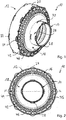
- Fig. 2 shows the bellows 10 according to Fig. 1 in a plan view, so that the rotationally symmetrical arrangement of the stiffening rib 42 as a circumferential, ie a closed circular ring forming, and the arrangement of the support ribs 44 and the radial ribs 46 is clearly visible. It is also easy to see that there are twice as many support ribs 44 as there are radial ribs 46.
- Fig. 3 now shows a cross section along the line II of Fig. 2 through the bellows 10.
- the formation of the membrane area 18 with a first membrane part 32 and a second, trough-shaped membrane part 34 can be clearly seen, as can the transition of the membrane area 18 into the second fastening area 14.
- the Stiffening rib 42 is formed with the support rib 44 and the radial rib 46 to form a common outer edge 48 (see Fig. 4 ).
- Fig. 4 shows a detail II of the Fig. 3 in detail.
- the transition region 16 is formed by a wall part 38 with an inner surface 39 which can be turned towards an outer joint part, not shown here.
- the transition region 16 is further formed by the one stiffening rib 42.
- the wall part 38 has a width b, which is determined by an underside 21 of the first binder seat region 20 of the first fastening region 12 and the transition into the first membrane part 32 of the membrane region 18.
- An upper one Surface 41 and a lower surface 43 of the stiffening rib 42 are slightly inclined to one another.
- the membrane part 18 shows between the first membrane part 32 and the second membrane part 34, which can only be seen in sections, the formation of a rounded part 35, which also Fig. 2 can be seen.
- an angle ⁇ is formed which is 5 °.
- the formation of the support rib 44 is clearly visible there.
- This forms a joint-free outer edge 48 with the first membrane part 32 or the rounded part 35 and an outer surface of the stiffening rib 42.
- the support rib 16 is arranged between an upper surface 41 of the stiffening rib 42 and a lower surface 11 of a protrusion 13 of the first fastening area 12.
- This also has a common outer edge 48 with the stiffening rib 42, so that overall a continuous, continuous, that is to say, jump-free outer edge 48, formed in the manner of a curve section, is formed.
- a height h 1 determined between the upper surface 33 of the first membrane section 32 and the lower surface 43 of the stiffening rib 42, is lower than a height h 2 , determined between the upper surface 41 of the stiffening rib 42 and the lower surface 11 of the overhang 13.
- the ratio of the heights h 1 : h 2 is approximately 0.75.
- the stiffening rib 42 is thus oriented closer to the first membrane part 32 of the membrane region 18, so that a height of the supporting ribs 44, which corresponds to the height h 1 , is made smaller than if the stiffening rib 42 were to be displaced further onto the first fastening region 12.
- the stiffening rib 42 can then absorb lower tangential forces than if it were arranged further displaced on the first fastening region 12.
- the protrusion 13 has an upper surface 15 which is flat and has no jumps with an upper side 19 of the first binder seat region 20.
- Fig. 5 shows a second embodiment of a bellows according to the invention, generally designated by reference numeral 10.
- the first attachment area 12 the second attachment area 14 and in particular the reinforcing ribs 46 are designed differently.
- the first fastening region 12 thus has a multiplicity of circumferential ribs 50 arranged in the first binder seat region 20.
- the first binder seat area 20 is defined by ear-shaped first positioning elements 22, but second positioning elements 24 are missing, as is the case in the first embodiment according to FIGS 1 to 4 available. Rather, a positioning or contact function is provided by the radial ribs 46, which are designed differently in comparison to the first embodiment and which protrude above an upper side of the first binder seat area 20.
- the second fastening region 14 differs from that of the first embodiment according to FIGS 1 to 4 to the extent that, as well as there, third positioning elements 28, in the form of an ear and evenly distributed in an edge region of the second fastening region 14, each arranged in pairs opposite one another, the fourth positioning elements 30 are designed differently, namely as a circumferential positioning surface, which due to a material reinforcement in FIG this area is provided immediately adjacent to the membrane area 18.
- Fig. 6 illustrates in a top view the configuration of the second embodiment of the rolling bellows 10 according to Fig. 1 .
- the protrusion of the radial ribs 46 over an upper side of the first binder seat area 20 can also be seen particularly well.
- Fig. 7 now shows a cross section through the second embodiment of the rolling bellows 10, wherein reinforcing ribs 44 and radial ribs 46 are not cut, but only the stiffening rib 42, which, like in the first embodiment according to FIGS 1 to 4 is arranged on a wall part 38 of the transition region 16.
- the stiffening rib 42 is longer in the second embodiment than in the first embodiment according to FIGS 1 to 4 .
- the first fastening region 12 can be seen with its first binder seat region 20 and a total of four circumferential ribs 50, a material accumulation 52 being recognizable on an underside 21 of the first fastening region 12 or the first binder seat region 20, which accumulates in a correspondingly designed, not shown in FIG a circumferential groove of an outer joint housing can be arranged.
- the second fastening area 14 with the ear-shaped third positioning elements 28 and the wall-shaped contact or positioning surface 30, which represents the fourth positioning element, is also good.
- Fig. 7 refer to.
- the membrane area 18 is similar to the membrane area 18 of the first embodiment according to FIGS 1 to 4 formed, however, a first material section 32 has a greater angle, based on the wall part 38 of the transition region 16, than in the first embodiment. Adjacent to the first material section 32, a rounding section 35 is formed in the membrane area 18, which is converted into a second material section 34, which is configured similarly to the first embodiment according to FIGS 1 to 4 .
- FIG. 8 the configuration of the plurality of radial ribs 46 with their contact or positioning surfaces 47 can be seen, which together with the first positioning elements 22 define the first binder seat area 20 with its top side 19 in the first fastening area 12.
- the four circumferential ribs 50 are arranged on the upper side 19 of the first binder seat region 20.
- a height h 2 between a surface of the circumferential stiffening rib 42 and a line defined by the underside 21 of the first fastening region 12 or the first binder seat region 20 is approximately 6 times as high as a height h, determined between a lower surface 43 of the circumferential stiffening rib 42 and a surface 33 of the first material section 32 of the membrane area 18 Fig.
- the drawing heights h 1 and h 2 shown spaced from an outer side 17 of the transition region 16.
- the heights h 1 and h 2 are, however, determined directly on the outside 17 of the transition region 16, thus opposite the inside surface 39 of the wall part 38.
- An angle ⁇ is between the lower surface 43 of the circumferential stiffening rib 42 and the surface 33 of the first material section 32 of the membrane area 38 can be determined and is approximately 20 °. The reason for this is the greater angling of the first material section 32 of the membrane area 18 in comparison to the first embodiment according to FIGS 1 to 4 .
- a width b defines the width or height of the wall section 38 of the first transition area 16 as between a line defined by the underside 21 of the first binder seat area 20 or the first fastening area 12 on the one hand and a parallel line passing through the transition point to the first material section 32 of the membrane area 18 Line.
- a rolling bellows is made available which has an improved radial strength, in particular at high revolutions, so that it can counteract the grease pressure arising due to the high centrifugal forces and also helps to remove the centrifugal forces acting on the bellows material itself.
- the bellows according to the invention has an increased service life in comparison to the roller bellows known from the prior art, at least in the region of high rotational speeds.
Landscapes
- Engineering & Computer Science (AREA)
- General Engineering & Computer Science (AREA)
- Mechanical Engineering (AREA)
- Diaphragms And Bellows (AREA)
- Sealing Devices (AREA)
Claims (11)
- Soufflet tubulaire (10) avec une première zone de fixation (12), une deuxième zone de fixation (14), une zone de transition (16) voisine de la première zone de fixation (12) et une zone de membrane (18) se raccordant à celle-ci et comprenant un premier élément de membrane (32) et un deuxième élément de membrane (34) qui sont reliés entre eux par une partie de courbure (35), caractérisé en ce qu'au moins une nervure de renforcement (42) est disposée sur une face extérieure (17) de la zone de transition (16) et qu'une multitude de nervures de support (44) sont disposées entre la nervure de renforcement (42) et le premier élément de membrane (32) de la zone de membrane (18), la zone de transition (16) comprenant la nervure de renforcement (42) et un élément de paroi (38) sur lequel la nervure de renforcement (42) est disposée, cet élément de paroi (38) se raccordant directement au premier élément de membrane (32) de la zone de membrane (18).
- Soufflet tubulaire (10) selon la revendication 1, caractérisé en ce que la nervure de renforcement (42) est disposée sur l'élément de paroi (38) de la zone de transition (16) sensiblement perpendiculairement à une surface intérieure (39) de l'élément de paroi (38).
- Soufflet tubulaire (10) selon une ou plusieurs des revendications précédentes, caractérisé en ce que la nervure de renforcement (42) sur la zone de transition (16) est disposée de manière décalée au-dessus du premier élément de membrane (32) de la zone de membrane (18).
- Soufflet tubulaire (10) selon une ou plusieurs des revendications précédentes, caractérisé en ce qu'une surface inférieure (43) de la nervure de renforcement (42) et une surface supérieure (33) d'un premier segment (32) de la zone de membrane (18) forment entre elles un angle α situé sur une plage d'environ 0° à environ 25°.
- Soufflet tubulaire (10) selon la revendication 4, caractérisé en ce que les nervures de support (44) et l'au moins une nervure de renforcement (42) sont disposées sensiblement perpendiculairement entre elles.
- Soufflet tubulaire (10) selon une ou plusieurs des revendications précédentes, caractérisé en ce qu'une multitude de nervures radiales (46) sont disposées au-dessus de la nervure de renforcement (42).
- Soufflet tubulaire (10) selon la revendication 6, caractérisé en ce que les nervures de support (44) et les nervures radiales (46) sont sensiblement alignées entre elles.
- Soufflet tubulaire (10) selon une ou plusieurs des revendications 6 et 7, caractérisé en ce qu'il est prévu davantage de nervures de support (44) que de nervures radiales (46).
- Articulation prismatique avec au moins un soufflet tubulaire (10) selon une ou plusieurs des revendications 1 à 8.
- Arbre avec au moins un soufflet tubulaire (10) selon une ou plusieurs des revendications 1 à 8.
- Dispositif d'articulation comprenant au moins un soufflet tubulaire (10) selon une ou plusieurs des revendications 1 à 8, au moins une articulation prismatique et un arbre.
Applications Claiming Priority (1)
| Application Number | Priority Date | Filing Date | Title |
|---|---|---|---|
| PCT/EP2017/054005 WO2018153440A1 (fr) | 2017-02-22 | 2017-02-22 | Soufflet tubulaire comprenant au moins une nervure de renforcement |
Publications (2)
| Publication Number | Publication Date |
|---|---|
| EP3586024A1 EP3586024A1 (fr) | 2020-01-01 |
| EP3586024B1 true EP3586024B1 (fr) | 2020-07-29 |
Family
ID=58108620
Family Applications (1)
| Application Number | Title | Priority Date | Filing Date |
|---|---|---|---|
| EP17706748.5A Active EP3586024B1 (fr) | 2017-02-22 | 2017-02-22 | Soufflet tubulaire comprenant au moins une nervure de renforcement |
Country Status (6)
| Country | Link |
|---|---|
| US (1) | US11248661B2 (fr) |
| EP (1) | EP3586024B1 (fr) |
| JP (1) | JP6903757B2 (fr) |
| CN (1) | CN110325754B (fr) |
| PT (1) | PT3586024T (fr) |
| WO (1) | WO2018153440A1 (fr) |
Families Citing this family (4)
| Publication number | Priority date | Publication date | Assignee | Title |
|---|---|---|---|---|
| US10788079B2 (en) * | 2017-03-08 | 2020-09-29 | Steering Solutions Ip Holding Corporation | Energy absorbing constant velocity joint boot assembly |
| DE102017221604A1 (de) * | 2017-11-30 | 2019-06-06 | Ford Global Technologies, Llc | Seitliche Antriebswelle eines Antriebsstranges eines Kraftfahrzeuges mit außenliegendem Gleichlaufgelenk |
| IT201900008751A1 (it) | 2019-06-12 | 2020-12-12 | Insit Ind S P A | Cuffia di riparo compatta per giunti omocinetici di autoveicoli |
| DE102021006381A1 (de) * | 2021-12-28 | 2023-06-29 | Neapco Intellecutal Property Holdings, LLC | Faltenbalg zum Schutz eines Übertragungsgelenks |
Family Cites Families (19)
| Publication number | Priority date | Publication date | Assignee | Title |
|---|---|---|---|---|
| US2062748A (en) * | 1936-07-06 | 1936-12-01 | Magna Products Corp | Guard for lever openings |
| SU819466A1 (ru) * | 1975-05-04 | 1981-04-07 | Всесоюзный Научно-Исследовательскийи Конструкторско-Технологическийинститут Компрессорного Машино-Строения | Уплотнительна манжета |
| US4826466A (en) * | 1987-09-11 | 1989-05-02 | Arco Industries Corporation | Steering column boot |
| DE10023795C2 (de) * | 2000-05-15 | 2002-03-28 | Gkn Automotive Gmbh | Rollbalg |
| EP1201950B1 (fr) * | 2000-10-25 | 2007-12-26 | Ford Global Technologies, LLC. | Soufflet pour joint universel |
| DE10153822C1 (de) * | 2001-11-05 | 2003-04-24 | Walterscheid Gmbh Gkn | Schutzanordnung für ein Gelenk, insbesondere Doppelkreuzgelenk |
| DE10313696B4 (de) * | 2003-03-27 | 2009-03-19 | Gkn Driveline International Gmbh | Faltenbalg |
| DE102004034772B4 (de) * | 2004-01-02 | 2011-03-03 | Gkn Driveline International Gmbh | Rollbalg mit Aussteifungen |
| TR200502100A2 (tr) * | 2005-06-03 | 2007-01-22 | Bsh Ev Aletler� Sanay� Ve T�Caret Anon�M ��Rket�@ | P |
| US20070173337A1 (en) * | 2006-01-26 | 2007-07-26 | Hans Wormsbaecher | Rolling boot assembly |
| DE102006027048B3 (de) * | 2006-06-10 | 2007-11-29 | Mtu Friedrichshafen Gmbh | Faltenbalg mit Knickschutz |
| JP5297524B2 (ja) * | 2008-06-27 | 2013-09-25 | ゲーカーエン ドライブライン インターナショナル ゲゼルシャフト ミト ベシュレンクテル ハフツング | 軸方向にずれた第1締付領域を備えるブーツ |
| JP5295364B2 (ja) | 2008-06-27 | 2013-09-18 | ゲーカーエン ドライブライン インターナショナル ゲゼルシャフト ミト ベシュレンクテル ハフツング | 移行領域を有する横揺れブーツ |
| JP2014526664A (ja) * | 2011-09-23 | 2014-10-06 | ジーケーエヌ・ドライブライン・ノースアメリカ・インコーポレーテッド | 高角等速ジョイント及びブーツ |
| CN104395629B (zh) | 2012-05-16 | 2016-12-14 | Gkn 动力传动系统国际有限责任公司 | 具有过渡区域的滚动保护罩 |
| DE202013009225U1 (de) * | 2013-10-18 | 2013-11-15 | Gkn Driveline International Gmbh | Dichtbalg mit Stützring und Gleichlaufgelenkanordnung mit einem solchen Dichtbalg |
| DE202013009239U1 (de) * | 2013-10-18 | 2013-11-15 | Gkn Driveline International Gmbh | Dichtbalg mit Stützring und Gleichlaufdrehgelenk mit einem solchen Dichtbalg |
| DE202013009221U1 (de) * | 2013-10-18 | 2013-11-15 | Gkn Driveline International Gmbh | Dichtbalg mit Kugelanschlag und Gleichlaufdrehgelenk mit einem solchen Dichtbalg |
| US10718372B2 (en) * | 2017-07-13 | 2020-07-21 | Federal-Mogul Motorparts Llc | Dust boot for a moveable joint |
-
2017
- 2017-02-22 PT PT177067485T patent/PT3586024T/pt unknown
- 2017-02-22 JP JP2019541756A patent/JP6903757B2/ja active Active
- 2017-02-22 WO PCT/EP2017/054005 patent/WO2018153440A1/fr unknown
- 2017-02-22 EP EP17706748.5A patent/EP3586024B1/fr active Active
- 2017-02-22 CN CN201780087109.5A patent/CN110325754B/zh active Active
- 2017-02-22 US US16/481,559 patent/US11248661B2/en active Active
Non-Patent Citations (1)
| Title |
|---|
| None * |
Also Published As
| Publication number | Publication date |
|---|---|
| JP2020508418A (ja) | 2020-03-19 |
| CN110325754B (zh) | 2022-02-22 |
| WO2018153440A1 (fr) | 2018-08-30 |
| CN110325754A (zh) | 2019-10-11 |
| US20190368551A1 (en) | 2019-12-05 |
| EP3586024A1 (fr) | 2020-01-01 |
| US11248661B2 (en) | 2022-02-15 |
| PT3586024T (pt) | 2020-10-07 |
| JP6903757B2 (ja) | 2021-07-14 |
Similar Documents
| Publication | Publication Date | Title |
|---|---|---|
| EP3586024B1 (fr) | Soufflet tubulaire comprenant au moins une nervure de renforcement | |
| EP2585737B1 (fr) | Engrenage | |
| DE102013213708A1 (de) | Schneckengetriebe für eine Lenkhilfevorrichtung eines Kraftfahrzeuges mit Spielausgleich | |
| EP2478235B1 (fr) | Roulement à rouleaux sphériques | |
| DE102012207529A1 (de) | Käfigsegment eines Kegelrollenlagers und Kegelrollenlager | |
| EP3044840A2 (fr) | Dispositif de dérivation | |
| DE102009044361A1 (de) | Fahrzeugluftreifen | |
| EP2893207B1 (fr) | Cage axiale pour corps de roulement cylindriques | |
| EP2478236B1 (fr) | Roulement à rouleaux sphériques | |
| DE102008026562A1 (de) | Wälzlager für hohe Drehzahlen | |
| DE102010003077A1 (de) | Gleitlagerschale | |
| DE102015201487A1 (de) | Zweireihiges Axialnadellager | |
| EP1978275B1 (fr) | Articulation, en particulier sur une plateforme pivotante entre un wagon avant et un wagon arrière d'un bus à plateforme pivotante | |
| EP3568604B1 (fr) | Soufflet comportant au moins une rainure interne | |
| EP3041385B1 (fr) | Galet de guidage | |
| DE102009031793A1 (de) | Antriebsanordnung für ein stufenlos verstellbares Getriebe eines Kraftfahrzeuges | |
| DE102008014702A1 (de) | Motoraufhängung für einen Axiallüfter und Verfahren zur Herstellung einer Motoraufhängung | |
| DE102007030982A1 (de) | Anordnung zur axialen Sicherung und/oder zum axialen Toleranzausgleich eines Maschinenelementes, insbesondere eines Lagers, auf oder an einer Welle | |
| EP2591245B1 (fr) | Articulation | |
| DE102017111996B4 (de) | Lageranordnung | |
| DE102018111726A1 (de) | Planetenträger mit Versteifungssicken; sowie Planetengetriebe | |
| AT507165B1 (de) | Ringförmiges futter für eine seilrolle bzw. eine umlenkscheibe einer seilbahn | |
| EP2904164B1 (fr) | Élément de surface | |
| DE202017002962U1 (de) | Laufrolle | |
| EP3568605B1 (fr) | Soufflet comportant au moins deux rainures dans les zones des lobes et/ou dans les zones de guidage |
Legal Events
| Date | Code | Title | Description |
|---|---|---|---|
| STAA | Information on the status of an ep patent application or granted ep patent |
Free format text: STATUS: UNKNOWN |
|
| STAA | Information on the status of an ep patent application or granted ep patent |
Free format text: STATUS: THE INTERNATIONAL PUBLICATION HAS BEEN MADE |
|
| PUAI | Public reference made under article 153(3) epc to a published international application that has entered the european phase |
Free format text: ORIGINAL CODE: 0009012 |
|
| STAA | Information on the status of an ep patent application or granted ep patent |
Free format text: STATUS: REQUEST FOR EXAMINATION WAS MADE |
|
| 17P | Request for examination filed |
Effective date: 20190822 |
|
| AK | Designated contracting states |
Kind code of ref document: A1 Designated state(s): AL AT BE BG CH CY CZ DE DK EE ES FI FR GB GR HR HU IE IS IT LI LT LU LV MC MK MT NL NO PL PT RO RS SE SI SK SM TR |
|
| AX | Request for extension of the european patent |
Extension state: BA ME |
|
| GRAP | Despatch of communication of intention to grant a patent |
Free format text: ORIGINAL CODE: EPIDOSNIGR1 |
|
| STAA | Information on the status of an ep patent application or granted ep patent |
Free format text: STATUS: GRANT OF PATENT IS INTENDED |
|
| INTG | Intention to grant announced |
Effective date: 20200128 |
|
| RAX | Requested extension states of the european patent have changed |
Extension state: ME Extension state: BA |
|
| GRAJ | Information related to disapproval of communication of intention to grant by the applicant or resumption of examination proceedings by the epo deleted |
Free format text: ORIGINAL CODE: EPIDOSDIGR1 |
|
| STAA | Information on the status of an ep patent application or granted ep patent |
Free format text: STATUS: REQUEST FOR EXAMINATION WAS MADE |
|
| DAV | Request for validation of the european patent (deleted) | ||
| DAX | Request for extension of the european patent (deleted) | ||
| GRAR | Information related to intention to grant a patent recorded |
Free format text: ORIGINAL CODE: EPIDOSNIGR71 |
|
| GRAS | Grant fee paid |
Free format text: ORIGINAL CODE: EPIDOSNIGR3 |
|
| INTC | Intention to grant announced (deleted) | ||
| STAA | Information on the status of an ep patent application or granted ep patent |
Free format text: STATUS: GRANT OF PATENT IS INTENDED |
|
| GRAA | (expected) grant |
Free format text: ORIGINAL CODE: 0009210 |
|
| STAA | Information on the status of an ep patent application or granted ep patent |
Free format text: STATUS: THE PATENT HAS BEEN GRANTED |
|
| INTG | Intention to grant announced |
Effective date: 20200617 |
|
| AK | Designated contracting states |
Kind code of ref document: B1 Designated state(s): AL AT BE BG CH CY CZ DE DK EE ES FI FR GB GR HR HU IE IS IT LI LT LU LV MC MK MT NL NO PL PT RO RS SE SI SK SM TR |
|
| REG | Reference to a national code |
Ref country code: CH Ref legal event code: EP |
|
| REG | Reference to a national code |
Ref country code: AT Ref legal event code: REF Ref document number: 1296153 Country of ref document: AT Kind code of ref document: T Effective date: 20200815 |
|
| REG | Reference to a national code |
Ref country code: IE Ref legal event code: FG4D Free format text: LANGUAGE OF EP DOCUMENT: GERMAN |
|
| REG | Reference to a national code |
Ref country code: DE Ref legal event code: R096 Ref document number: 502017006416 Country of ref document: DE |
|
| REG | Reference to a national code |
Ref country code: PT Ref legal event code: SC4A Ref document number: 3586024 Country of ref document: PT Date of ref document: 20201007 Kind code of ref document: T Free format text: AVAILABILITY OF NATIONAL TRANSLATION Effective date: 20200928 |
|
| REG | Reference to a national code |
Ref country code: LT Ref legal event code: MG4D |
|
| REG | Reference to a national code |
Ref country code: NL Ref legal event code: MP Effective date: 20200729 |
|
| PG25 | Lapsed in a contracting state [announced via postgrant information from national office to epo] |
Ref country code: FI Free format text: LAPSE BECAUSE OF FAILURE TO SUBMIT A TRANSLATION OF THE DESCRIPTION OR TO PAY THE FEE WITHIN THE PRESCRIBED TIME-LIMIT Effective date: 20200729 Ref country code: GR Free format text: LAPSE BECAUSE OF FAILURE TO SUBMIT A TRANSLATION OF THE DESCRIPTION OR TO PAY THE FEE WITHIN THE PRESCRIBED TIME-LIMIT Effective date: 20201030 Ref country code: HR Free format text: LAPSE BECAUSE OF FAILURE TO SUBMIT A TRANSLATION OF THE DESCRIPTION OR TO PAY THE FEE WITHIN THE PRESCRIBED TIME-LIMIT Effective date: 20200729 Ref country code: ES Free format text: LAPSE BECAUSE OF FAILURE TO SUBMIT A TRANSLATION OF THE DESCRIPTION OR TO PAY THE FEE WITHIN THE PRESCRIBED TIME-LIMIT Effective date: 20200729 Ref country code: LT Free format text: LAPSE BECAUSE OF FAILURE TO SUBMIT A TRANSLATION OF THE DESCRIPTION OR TO PAY THE FEE WITHIN THE PRESCRIBED TIME-LIMIT Effective date: 20200729 Ref country code: BG Free format text: LAPSE BECAUSE OF FAILURE TO SUBMIT A TRANSLATION OF THE DESCRIPTION OR TO PAY THE FEE WITHIN THE PRESCRIBED TIME-LIMIT Effective date: 20201029 Ref country code: NO Free format text: LAPSE BECAUSE OF FAILURE TO SUBMIT A TRANSLATION OF THE DESCRIPTION OR TO PAY THE FEE WITHIN THE PRESCRIBED TIME-LIMIT Effective date: 20201029 Ref country code: SE Free format text: LAPSE BECAUSE OF FAILURE TO SUBMIT A TRANSLATION OF THE DESCRIPTION OR TO PAY THE FEE WITHIN THE PRESCRIBED TIME-LIMIT Effective date: 20200729 |
|
| PG25 | Lapsed in a contracting state [announced via postgrant information from national office to epo] |
Ref country code: IS Free format text: LAPSE BECAUSE OF FAILURE TO SUBMIT A TRANSLATION OF THE DESCRIPTION OR TO PAY THE FEE WITHIN THE PRESCRIBED TIME-LIMIT Effective date: 20201129 Ref country code: LV Free format text: LAPSE BECAUSE OF FAILURE TO SUBMIT A TRANSLATION OF THE DESCRIPTION OR TO PAY THE FEE WITHIN THE PRESCRIBED TIME-LIMIT Effective date: 20200729 Ref country code: RS Free format text: LAPSE BECAUSE OF FAILURE TO SUBMIT A TRANSLATION OF THE DESCRIPTION OR TO PAY THE FEE WITHIN THE PRESCRIBED TIME-LIMIT Effective date: 20200729 Ref country code: PL Free format text: LAPSE BECAUSE OF FAILURE TO SUBMIT A TRANSLATION OF THE DESCRIPTION OR TO PAY THE FEE WITHIN THE PRESCRIBED TIME-LIMIT Effective date: 20200729 |
|
| PG25 | Lapsed in a contracting state [announced via postgrant information from national office to epo] |
Ref country code: NL Free format text: LAPSE BECAUSE OF FAILURE TO SUBMIT A TRANSLATION OF THE DESCRIPTION OR TO PAY THE FEE WITHIN THE PRESCRIBED TIME-LIMIT Effective date: 20200729 |
|
| PG25 | Lapsed in a contracting state [announced via postgrant information from national office to epo] |
Ref country code: RO Free format text: LAPSE BECAUSE OF FAILURE TO SUBMIT A TRANSLATION OF THE DESCRIPTION OR TO PAY THE FEE WITHIN THE PRESCRIBED TIME-LIMIT Effective date: 20200729 Ref country code: CZ Free format text: LAPSE BECAUSE OF FAILURE TO SUBMIT A TRANSLATION OF THE DESCRIPTION OR TO PAY THE FEE WITHIN THE PRESCRIBED TIME-LIMIT Effective date: 20200729 Ref country code: DK Free format text: LAPSE BECAUSE OF FAILURE TO SUBMIT A TRANSLATION OF THE DESCRIPTION OR TO PAY THE FEE WITHIN THE PRESCRIBED TIME-LIMIT Effective date: 20200729 Ref country code: EE Free format text: LAPSE BECAUSE OF FAILURE TO SUBMIT A TRANSLATION OF THE DESCRIPTION OR TO PAY THE FEE WITHIN THE PRESCRIBED TIME-LIMIT Effective date: 20200729 Ref country code: SM Free format text: LAPSE BECAUSE OF FAILURE TO SUBMIT A TRANSLATION OF THE DESCRIPTION OR TO PAY THE FEE WITHIN THE PRESCRIBED TIME-LIMIT Effective date: 20200729 |
|
| REG | Reference to a national code |
Ref country code: DE Ref legal event code: R097 Ref document number: 502017006416 Country of ref document: DE |
|
| PG25 | Lapsed in a contracting state [announced via postgrant information from national office to epo] |
Ref country code: AL Free format text: LAPSE BECAUSE OF FAILURE TO SUBMIT A TRANSLATION OF THE DESCRIPTION OR TO PAY THE FEE WITHIN THE PRESCRIBED TIME-LIMIT Effective date: 20200729 |
|
| PLBE | No opposition filed within time limit |
Free format text: ORIGINAL CODE: 0009261 |
|
| STAA | Information on the status of an ep patent application or granted ep patent |
Free format text: STATUS: NO OPPOSITION FILED WITHIN TIME LIMIT |
|
| PG25 | Lapsed in a contracting state [announced via postgrant information from national office to epo] |
Ref country code: SK Free format text: LAPSE BECAUSE OF FAILURE TO SUBMIT A TRANSLATION OF THE DESCRIPTION OR TO PAY THE FEE WITHIN THE PRESCRIBED TIME-LIMIT Effective date: 20200729 |
|
| 26N | No opposition filed |
Effective date: 20210430 |
|
| PG25 | Lapsed in a contracting state [announced via postgrant information from national office to epo] |
Ref country code: MC Free format text: LAPSE BECAUSE OF FAILURE TO SUBMIT A TRANSLATION OF THE DESCRIPTION OR TO PAY THE FEE WITHIN THE PRESCRIBED TIME-LIMIT Effective date: 20200729 |
|
| GBPC | Gb: european patent ceased through non-payment of renewal fee |
Effective date: 20210222 |
|
| REG | Reference to a national code |
Ref country code: BE Ref legal event code: MM Effective date: 20210228 |
|
| PG25 | Lapsed in a contracting state [announced via postgrant information from national office to epo] |
Ref country code: CH Free format text: LAPSE BECAUSE OF NON-PAYMENT OF DUE FEES Effective date: 20210228 Ref country code: LI Free format text: LAPSE BECAUSE OF NON-PAYMENT OF DUE FEES Effective date: 20210228 Ref country code: LU Free format text: LAPSE BECAUSE OF NON-PAYMENT OF DUE FEES Effective date: 20210222 |
|
| PG25 | Lapsed in a contracting state [announced via postgrant information from national office to epo] |
Ref country code: GB Free format text: LAPSE BECAUSE OF NON-PAYMENT OF DUE FEES Effective date: 20210222 Ref country code: IE Free format text: LAPSE BECAUSE OF NON-PAYMENT OF DUE FEES Effective date: 20210222 |
|
| PG25 | Lapsed in a contracting state [announced via postgrant information from national office to epo] |
Ref country code: BE Free format text: LAPSE BECAUSE OF NON-PAYMENT OF DUE FEES Effective date: 20210228 |
|
| REG | Reference to a national code |
Ref country code: AT Ref legal event code: MM01 Ref document number: 1296153 Country of ref document: AT Kind code of ref document: T Effective date: 20220222 |
|
| PG25 | Lapsed in a contracting state [announced via postgrant information from national office to epo] |
Ref country code: AT Free format text: LAPSE BECAUSE OF NON-PAYMENT OF DUE FEES Effective date: 20220222 |
|
| PGFP | Annual fee paid to national office [announced via postgrant information from national office to epo] |
Ref country code: FR Payment date: 20230220 Year of fee payment: 7 |
|
| PGFP | Annual fee paid to national office [announced via postgrant information from national office to epo] |
Ref country code: IT Payment date: 20230228 Year of fee payment: 7 |
|
| PG25 | Lapsed in a contracting state [announced via postgrant information from national office to epo] |
Ref country code: CY Free format text: LAPSE BECAUSE OF FAILURE TO SUBMIT A TRANSLATION OF THE DESCRIPTION OR TO PAY THE FEE WITHIN THE PRESCRIBED TIME-LIMIT Effective date: 20200729 |
|
| PG25 | Lapsed in a contracting state [announced via postgrant information from national office to epo] |
Ref country code: HU Free format text: LAPSE BECAUSE OF FAILURE TO SUBMIT A TRANSLATION OF THE DESCRIPTION OR TO PAY THE FEE WITHIN THE PRESCRIBED TIME-LIMIT; INVALID AB INITIO Effective date: 20170222 |
|
| PG25 | Lapsed in a contracting state [announced via postgrant information from national office to epo] |
Ref country code: SI Free format text: LAPSE BECAUSE OF FAILURE TO SUBMIT A TRANSLATION OF THE DESCRIPTION OR TO PAY THE FEE WITHIN THE PRESCRIBED TIME-LIMIT Effective date: 20200729 |
|
| PG25 | Lapsed in a contracting state [announced via postgrant information from national office to epo] |
Ref country code: MK Free format text: LAPSE BECAUSE OF FAILURE TO SUBMIT A TRANSLATION OF THE DESCRIPTION OR TO PAY THE FEE WITHIN THE PRESCRIBED TIME-LIMIT Effective date: 20200729 |
|
| PGFP | Annual fee paid to national office [announced via postgrant information from national office to epo] |
Ref country code: DE Payment date: 20240216 Year of fee payment: 8 Ref country code: PT Payment date: 20240220 Year of fee payment: 8 |