EP3585955B1 - Substrate having decorated surface and method of production - Google Patents
Substrate having decorated surface and method of production Download PDFInfo
- Publication number
- EP3585955B1 EP3585955B1 EP18757976.8A EP18757976A EP3585955B1 EP 3585955 B1 EP3585955 B1 EP 3585955B1 EP 18757976 A EP18757976 A EP 18757976A EP 3585955 B1 EP3585955 B1 EP 3585955B1
- Authority
- EP
- European Patent Office
- Prior art keywords
- decorated
- module
- particles
- coloured particles
- exposed surface
- Prior art date
- Legal status (The legal status is an assumption and is not a legal conclusion. Google has not performed a legal analysis and makes no representation as to the accuracy of the status listed.)
- Active
Links
Images








Classifications
-
- B—PERFORMING OPERATIONS; TRANSPORTING
- B44—DECORATIVE ARTS
- B44C—PRODUCING DECORATIVE EFFECTS; MOSAICS; TARSIA WORK; PAPERHANGING
- B44C1/00—Processes, not specifically provided for elsewhere, for producing decorative surface effects
-
- B—PERFORMING OPERATIONS; TRANSPORTING
- B44—DECORATIVE ARTS
- B44C—PRODUCING DECORATIVE EFFECTS; MOSAICS; TARSIA WORK; PAPERHANGING
- B44C5/00—Processes for producing special ornamental bodies
- B44C5/04—Ornamental plaques, e.g. decorative panels, decorative veneers
-
- C—CHEMISTRY; METALLURGY
- C04—CEMENTS; CONCRETE; ARTIFICIAL STONE; CERAMICS; REFRACTORIES
- C04B—LIME, MAGNESIA; SLAG; CEMENTS; COMPOSITIONS THEREOF, e.g. MORTARS, CONCRETE OR LIKE BUILDING MATERIALS; ARTIFICIAL STONE; CERAMICS; REFRACTORIES; TREATMENT OF NATURAL STONE
- C04B33/00—Clay-wares
- C04B33/02—Preparing or treating the raw materials individually or as batches
- C04B33/13—Compounding ingredients
- C04B33/14—Colouring matters
-
- D—TEXTILES; PAPER
- D06—TREATMENT OF TEXTILES OR THE LIKE; LAUNDERING; FLEXIBLE MATERIALS NOT OTHERWISE PROVIDED FOR
- D06N—WALL, FLOOR, OR LIKE COVERING MATERIALS, e.g. LINOLEUM, OILCLOTH, ARTIFICIAL LEATHER, ROOFING FELT, CONSISTING OF A FIBROUS WEB COATED WITH A LAYER OF MACROMOLECULAR MATERIAL; FLEXIBLE SHEET MATERIAL NOT OTHERWISE PROVIDED FOR
- D06N5/00—Roofing materials comprising a fibrous web coated with bitumen or another polymer, e.g. pitch
- D06N5/003—Roofing materials comprising a fibrous web coated with bitumen or another polymer, e.g. pitch coated with bitumen
-
- E—FIXED CONSTRUCTIONS
- E04—BUILDING
- E04D—ROOF COVERINGS; SKY-LIGHTS; GUTTERS; ROOF-WORKING TOOLS
- E04D1/00—Roof covering by making use of tiles, slates, shingles, or other small roofing elements
- E04D1/12—Roofing elements shaped as plain tiles or shingles, i.e. with flat outer surface
- E04D1/20—Roofing elements shaped as plain tiles or shingles, i.e. with flat outer surface of plastics; of asphalt; of fibrous materials
-
- E—FIXED CONSTRUCTIONS
- E04—BUILDING
- E04D—ROOF COVERINGS; SKY-LIGHTS; GUTTERS; ROOF-WORKING TOOLS
- E04D1/00—Roof covering by making use of tiles, slates, shingles, or other small roofing elements
- E04D1/12—Roofing elements shaped as plain tiles or shingles, i.e. with flat outer surface
- E04D1/22—Roofing elements shaped as plain tiles or shingles, i.e. with flat outer surface of specified materials not covered by any one of groups E04D1/14 - E04D1/205, or of combinations of materials, where at least one is not covered by any one of groups E04D1/14 - E04D1/205
-
- E—FIXED CONSTRUCTIONS
- E04—BUILDING
- E04D—ROOF COVERINGS; SKY-LIGHTS; GUTTERS; ROOF-WORKING TOOLS
- E04D1/00—Roof covering by making use of tiles, slates, shingles, or other small roofing elements
- E04D1/26—Strip-shaped roofing elements simulating a repetitive pattern, e.g. appearing as a row of shingles
- E04D1/265—Strip-shaped roofing elements simulating a repetitive pattern, e.g. appearing as a row of shingles the roofing elements being rigid, e.g. made of metal, wood or concrete
-
- E—FIXED CONSTRUCTIONS
- E04—BUILDING
- E04D—ROOF COVERINGS; SKY-LIGHTS; GUTTERS; ROOF-WORKING TOOLS
- E04D7/00—Roof covering exclusively consisting of sealing masses applied in situ; Gravelling of flat roofs
-
- B—PERFORMING OPERATIONS; TRANSPORTING
- B05—SPRAYING OR ATOMISING IN GENERAL; APPLYING FLUENT MATERIALS TO SURFACES, IN GENERAL
- B05D—PROCESSES FOR APPLYING FLUENT MATERIALS TO SURFACES, IN GENERAL
- B05D2401/00—Form of the coating product, e.g. solution, water dispersion, powders or the like
-
- B—PERFORMING OPERATIONS; TRANSPORTING
- B05—SPRAYING OR ATOMISING IN GENERAL; APPLYING FLUENT MATERIALS TO SURFACES, IN GENERAL
- B05D—PROCESSES FOR APPLYING FLUENT MATERIALS TO SURFACES, IN GENERAL
- B05D3/00—Pretreatment of surfaces to which liquids or other fluent materials are to be applied; After-treatment of applied coatings, e.g. intermediate treating of an applied coating preparatory to subsequent applications of liquids or other fluent materials
- B05D3/02—Pretreatment of surfaces to which liquids or other fluent materials are to be applied; After-treatment of applied coatings, e.g. intermediate treating of an applied coating preparatory to subsequent applications of liquids or other fluent materials by baking
- B05D3/0218—Pretreatment, e.g. heating the substrate
-
- B—PERFORMING OPERATIONS; TRANSPORTING
- B05—SPRAYING OR ATOMISING IN GENERAL; APPLYING FLUENT MATERIALS TO SURFACES, IN GENERAL
- B05D—PROCESSES FOR APPLYING FLUENT MATERIALS TO SURFACES, IN GENERAL
- B05D7/00—Processes, other than flocking, specially adapted for applying liquids or other fluent materials to particular surfaces or for applying particular liquids or other fluent materials
- B05D7/02—Processes, other than flocking, specially adapted for applying liquids or other fluent materials to particular surfaces or for applying particular liquids or other fluent materials to macromolecular substances, e.g. rubber
-
- E—FIXED CONSTRUCTIONS
- E04—BUILDING
- E04D—ROOF COVERINGS; SKY-LIGHTS; GUTTERS; ROOF-WORKING TOOLS
- E04D1/00—Roof covering by making use of tiles, slates, shingles, or other small roofing elements
- E04D2001/005—Roof covering by making use of tiles, slates, shingles, or other small roofing elements the roofing elements having a granulated surface
-
- E—FIXED CONSTRUCTIONS
- E04—BUILDING
- E04D—ROOF COVERINGS; SKY-LIGHTS; GUTTERS; ROOF-WORKING TOOLS
- E04D1/00—Roof covering by making use of tiles, slates, shingles, or other small roofing elements
- E04D1/30—Special roof-covering elements, e.g. ridge tiles, gutter tiles, gable tiles, ventilation tiles
- E04D2001/304—Special roof-covering elements, e.g. ridge tiles, gutter tiles, gable tiles, ventilation tiles at roof intersections, e.g. valley tiles, ridge tiles
- E04D2001/305—Ridge or hip tiles
Definitions
- the present invention generally relates to substrates having a decorated surface and a method of producing a substrate having a decorated surface.
- the present invention relates to a roofing, cladding, and/or siding product or a coating or layer of a coating for a roofing, cladding, and/or siding product having a decorated surface and a methods of producing the same.
- the present invention also relates to roofing, cladding, and/or siding products and assemblies of such products, for installation onto a building surface and systems and methods of manufacture of roofing, cladding, and/or siding products.
- roofing, cladding and/or siding products there are a variety of known roofing, cladding and/or siding products, each of which have particular appearance and performance characteristics for installing onto building surfaces according to a user's preference.
- Well-known products include asphalt shingles, slate, tiles, concrete tiles, etc.
- Such products may be manufactured from natural materials such as stone, clay, timber, etc. or from synthetic materials, such as polymers and composites thereof.
- synthetic materials for manufacturing such products can provide a number of advantages over the use of natural materials, for example improved performance and/or processing characteristics and/or cost benefits.
- synthetic materials it is often desirable from an aesthetic perspective for such products to mimic the appearance of or resemble a natural material. However, this can be difficult to achieve while preserving other important characteristics of the product, for example durability.
- a mat of fiberglass or cellulose fibers is coated with hot asphalt and granules of a ceramic material of the desired colour (for example, stones coated with ceramic of consistent colour) applied to asphalt coating to provide a surface having the desired appearance and to protect the asphalt from UV degradation.
- a ceramic material of the desired colour for example, stones coated with ceramic of consistent colour
- Some of the granules of the ceramic material do not strongly adhere to the surface of the asphalt and are easily removed, for example by rubbing during transit or installation or by walking on following installation especially when hot, potentially adversely affecting the appearance of the product.
- US 2011/0081553 discloses the use of a melt-in-place acrylic binder that is applied to a substrate in the form of a powder, followed by a fusing together of the binder powder by heat or radiation.
- substrates having a decorated surface there is an ongoing need to provide substrates having a decorated surface and methods of producing substrates having a decorated surface, such as roofing, cladding and/or siding products or coatings or layers of coatings for roofing, cladding, and/or siding products which provide the same or similar appearance as those products which have been used traditionally, yet which also provide for performance characteristics.
- substrates having a decorated surface such as roofing, cladding and/or siding products or coatings or layers of coatings for roofing, cladding, and/or siding products which provide the same or similar appearance as those products which have been used traditionally, yet which also provide for performance characteristics.
- to provide for such alternatives which are capable of being industrially produced in suitable quantities, and/or from alternative materials.
- Relative terms such as “lower” or “bottom”, “upper” or “top,” and “front” or “back” may be used herein to describe one element's relationship to another element as illustrated in the Figures. It will be understood that relative terms are intended to encompass different orientations of the device in addition to the orientation depicted in the Figures. For example, if the device in one of the figures is turned over, elements described as being on the “lower” side of other elements would then be oriented on “upper” sides of the other elements. The exemplary term “lower”, therefore, encompasses both an orientation of “lower” and “upper,” depending of the particular orientation of the figure.
- formed surface refers to a molded segment of a polymeric material corresponding to an individual die or mold of a continuous forming machine.
- the term "building surface" refers to a wall surface or a top surface, etc. of a building, e.g. an exterior wall, a roof, a ceiling, etc., unless otherwise specified.
- the building surface typically comprises a waterproof roofing product attached to the roof deck adjacent an eave of the roof for preventing water damage to the roof deck and an interior of a building from wind-blown rain or water buildup on the roof.
- the roof deck is typically made of an underlying material, such as plywood.
- the waterproof membrane may be any of a number of waterproof roofing membranes or underlay known in the art such as but not limited to bituminous waterproof membranes, modified bituminous roofing membranes, self-adhering roofing membranes, or single ply waterproofing roofing membranes (e.g. EPDM waterproof roofing membranes, PVC waterproof roofing membranes, TPO waterproof roofing membranes, synthetic underlay).
- One exemplary membrane sheet is Deck-Armor TM Roof Protection, manufactured by GAF Corp., Wayne, New Jersey.
- the terms “profiled” and/or “contoured” mean having a region, or regions which extend above or below a notional planar surface lying along the longitudinal axis of the product. This includes profiling or contouring of only one upper or lower surface, and/or profiling or contouring of an entire thickness of material such that the upper and lower surfaces have the same relative degree of extension above or below the notional planar surface.
- roofing means the provision of a protective covering on the roof surface of a building.
- a protective covering might take the form of shingles, tiles, panels, shakes, planks, boards, modules, moldings or sheets.
- cladding and/or “siding” mean the provision of a protective covering on a side or other surface of a building.
- a protective covering might take the form of shingles, tiles, panels, shakes, planks, boards, modules, moldings or sheets.
- polymer refers to organic polymers, preferably synthetic polymers, including homopolymers, copolymers, polymer alloys, polymer blends, and polymers with or without additives included therein.
- mechanical bond means a bond between surfaces which have physical features to create more bonding surface area.
- the surfaces may have surface textures or other three-dimensional features which allow keying, interlocking, increased friction fit, etc., between the surfaces bonded.
- w/w when referring to a component of a layer, refers to the weight of the constituents or components making up the total weight of a layer so formed.
- the present invention relates to a method of producing a substrate having a decorated surface.
- the method can be used to provide decorated surfaces having a wide range of different visual appearances, including the appearance of natural materials such as slate, etc.
- a decorated surface may provide for altered physical or structural features, such as grip, texture, etc, or other properties, such as stability to light or heat.
- the method comprises providing two or more pluralities of coloured particles having an initial colour and an exposed surface comprising one or more polymer.
- the coloured particles may be selected to provide a desired in colour in the decorated surface, for example a colour in contrast with the colour of one or more other pluralities of coloured particles or with the colour if any of the surface to be decorated.
- the variation in colour or coloured regions of the decorated surface provided by the coloured particles may vary in size shape.
- the initial colour of the coloured particles may change during the processing conditions for producing the decorated surface or on ageing of the substrate. For example, when the substrate comprises a roofing, cladding or siding product or coating or layer of a coating therefore, the initial colour may change over time on prolonged exposure of the product to UV light and/or heat.
- the initial colour of the coloured particles may also change depending on the shape of the coloured particles.
- the initial colour of the particles may be provided by one or more colourants. Suitable colourants will be apparent to those skilled in the art and will depend on the desired initial colour (or final colour on ageing).
- the colourant may be organic or inorganic, for example a metal salt, such as a metal oxide.
- the colourant is a pigment or dye.
- the colourant may be one or more of commercially available pigments.
- colourants include but are not limited to titanium dioxide, red iron oxide, lead chromate, ultramarine blue, molybdate orange, phthalocyanine blue, quinacridone, phthalocyanine green, carbon black, red lake C, black iron oxide; azo, anthraquinone, perinone, quinoline, pyrazolone, dioxazine, isoindoline, phthalocyanine, quinacridone and coumarin derivatives; and cadmium, chromates, iron blue, and cobalt blue. Mixtures of these and other pigments may be used to provide a desired colour. The amount of the one or more colourants in the coloured particles, where applicable, will depend the colourant(s) used.
- the colored particles may be of any suitable initial colour, including black or white, and may be transparent, translucent or opaque.
- each particle is polymeric in nature, due to the presence of the one or more polymers.
- the particles comprise one or more coloured polymers.
- the particles comprise a polymeric matrix comprising the one or more polymers within which one or more colourants (and optionally one or more other components) are dispersed.
- the particles comprises one or more coatings, the outermost coating defining the exposed surface of the particles comprising the one or more polymers within which one or more colourants (and optionally one or more other components of the particles are encapsulated.
- the coloured particles are polymer particles.
- the coloured particles are provided as discrete or separate particles or divided fragments in any suitable form, for example a powder, pellets, beads, or shredded or ground pellets or beads.
- the form may depend on the methods by which the coloured particles are obtained.
- the form of the coloured particles may also depend on the size or shape of the coloured particles desired for a particular application. Differently shaped particles of the same initial colour may, for example, differ in the degree to which they reflect or refract light leading a different visual appearance in the decorated surface.
- the coloured particles may be obtained by any suitable method known in the art.
- coloured particles comprising a polymer matrix comprising the one or more polymers and one or more colourants dispersed therein may be obtained from a suitably coloured masterbatch.
- the coloured masterbatch may be compounded with or into the one or more polymers and then processed into a shape, for example by grinding, crushing, shredding, palletization, stranding, forming into droplets, etc.
- Coloured particles comprising a coating comprising the one or more polymers that encapsulates one or more colourants may be prepared by coating or encapsulation methods well known in the art. The thickness of the coating can vary, for example from nanometers or micrometers, or millimeters.
- the two or more pluralities of coloured particles may be selected such that the particles and/or the one or more polymers of the exposed surface of the particles have an MFI and/or such that the particles have an average particles size effective at the temperature and pressure to which the coloured particles and/or surface to be decorated are exposed to provide a desired visual appearance in and/or on the decorated surface.
- the visual appearance of a decorated surface produced in accordance with the method of the invention can vary depending on the size of the coloured particles and/or the MFI of the coloured particles and/or one or more polymers of the exposed surface of the particles.
- it is possible to control the visual appearance of the decorated surface by selecting coloured particles having such characteristics effective to provide a desired appearance.
- the melt flow index (MFI) of a polymer is a measure of the mass of polymer (in grams) that is extruded through a capillary die at a certain temperature and force over a ten minute period. MFI may be determined by a procedure in accordance with ASTM D1238: 13 or ISO 1133.1 standards.
- the MFI of the one or more polymers of the exposed surface of coloured particles may be determined by testing the MFI of the one or polymers prior to producing the coloured particles or, in some embodiments, by testing the coloured particles themselves.
- the exposed surface of the coloured particles comprises two or more polymers, the MFI of each of the two or more polymers is such that the coloured particles are effective to provide the desired visual appearance. In some embodiments, the MFI of each of the two or more polymers is within a predetermined MFI range, for example from 0 to 10 or from 0 to 5.
- the two or more pluralities of coloured particles have an MFI from about 0 to about 50, including fractional melts from 0 to 1.
- the use of coloured particles having an exposed surface comprising one or more polymers having a low MFI, for example from about 1 to 10 in the method of the present invention can provide a visual appearance of for example discrete, well defined particles embedded in or on the decorated surface; while the use of coloured particles wherein the one or more polymers of the exposed surface have a medium to high MFI, for example from about 20 to 50, can provide a visual appearance of for example diffuse, blurred, poorly defined, or washed-out etc coloured regions in the decorated surface at the same temperature and pressure.
- the coloured particles of one or more pluralities of particles may be of a predetermined average particle size, for example an average particle size from about 0.05 mm to about 5 mm. Average particle size may be measured by for example laser diffraction.
- Particles of a desired average particles size may be obtained by screening and sieving a mixture comprising particles of various sizes using meshes of appropriate size with vibration. Such mixtures of particles of various sizes may be produced directly by the method employed to form the particles (from a liquid, molten, or semi molten mixture)or by post formation processing of the particles, such as reducing the size of particles of a larger size, for example by milling pellets or beads.
- coloured particles of a desired average particle size are produced the method by which the coloured particles are formed (i.e. such that no post formation processing is required).
- the one or more polymers of the exposed surface of the coloured particles and the one or more polymer of the exposed surface to be decorated may be the same or different.
- the coloured particles are selected such that the one or polymers of the exposed surface of the particles are capable of providing for fusion into or to or coalesce with the one or more polymers of the exposed surface to be decorated at the temperature and pressure that are controlled over a period of time in the method to produce the decorated surface.
- the coloured particles and/or one or more polymers of the exposed surface of the particles may be miscible or compatible with the exposed surface to be decorated and/or one or more polymers of the exposed surface to be decorated at a temperature greater than the glass transition temperature (Tg) of the coloured particles and/or one or more polymers of the exposed surface of the particles and/or a temperature greater than the Tg of the exposed surface to be decorated and/or one or more polymers of the exposed surface to be decorated, for example a temperature at least 1°C, at least 5°C or at least 10°C greater than the Tg.
- Tg glass transition temperature
- the glass transition temperature (or Tg) of a polymer is the temperature at which an amorphous polymer or amorphous regions of a polymer is or are transformed, in a reversible way, from a hard and relatively brittle state to a viscous or rubbery condition.
- the glass transition temperature may be determined by a procedure in accordance with ASTM E1356, ASTM E1640, ASTM D6604, ISO 11357.2, or ISO 6721 standards.
- miscible and related terms such as “miscibility” with reference to a combination of polymers means capable of forming a single polymeric phase. Miscibility may exist over certain ranges of temperature, pressure, and composition. The presence of a single polymeric phase may be determined by for example light scattering, X-ray scattering, and neutron scattering.
- compatible with reference to a combination of polymers means capable of forming an immiscible polymer blend that exhibits macroscopically uniform physical properties, for example a single Tg or optical purity.
- the inventors believe that a decorated surface having a continuous or unified polymeric matrix may be formed on fusion or coalescence of the coloured particles.
- the coloured particles and/or one or more polymers of the exposed surface of the coloured particles have a Tg of about 200°C or less, including 0°C or less.
- the coloured particles and/or the one or more polymers of the exposed surface of the coloured particles may have a heat deflection temperature (HDT) of at least about 20°C, such as at least 40°C, for example from 60 to 200, or 60 to 100°C.
- HDT heat deflection temperature
- Such an HDT may be useful for example, in roofing, cladding or siding products.
- Such an HDT may be provided by a blend of two or more polymers, each polymer having a different HDT.
- HDT is the temperature at which a polymer deforms by a specified amount under a specified load. HDT may be determined by a procedure in accordance with ASTM D 648:16 or ISO 75 standards.
- the coloured particles may be of a predetermined shape, such as spherical, cylindrical, cone-shaped, etc., or of random shape; or a mixture thereof. Coloured particles of various shapes may be obtained by various methods known to those skilled in the art, such as shredding, grinding, densifying (increasing the bulk density of the particles by for example heating), etc.
- the one or more polymers of the exposed surface of the coloured particles can be selected from a wide range of suitable polymers.
- suitable polymers include but are not limited to polystyrene (GPPS), polyethylene terephthalate (PET), polyester methacrylate (PEM), high impact polystyrene (HIPS), acrylonitrile butadiene styrene (ABS), polyvinyl chloride (PVC), polyurethanes (PU), polyethylene (PE) including homopolymer, copolymer, block copolymer and terpolymer forms, polylactic acid (PLA), nylon (PA), acrylics (PMMA), high density polyethylene (HDPE), low density polyethylene (LDPE), linear low density polyethylene (LLDPE), medium density polyethylene (MDPE), cross linked polyethylene (PEX), thermoplastic elastomer (TPE), thermoplastic polyolefin (TPO), thermoplastic rubber (TPR), polypropylene (PP), including homopolymer and copo
- the coloured particles and/or one or more polymers of the exposed surface of the coloured particles are generally selected such that that they do not adversely affect the physical, structural, or aesthetic characteristics of the decorated surface, for example compared to the physical, structural, or aesthetic characteristics of the exposed surface to be decorated or coloured particles.
- the coloured particles and/or one or more polymers may be selected such that they do not degrade or cause catalytic degradation or cause migration or hydrolysis of one or more components of the coloured particles or surface to be decorated in the decorated surface, do not substantially change the Tg of the decorated surface compared to the surface to be decorated, or do not substantially change the thermal expansion or contraction properties (e.g. the coefficient of thermal expansion) of the surface to be decorated.
- Decorated surfaces having a range of different visual appearances may be produced by the method of the present invention.
- the coloured particles used in the method can be selected based on characteristics, such as MFI, Tg, HDT, and/or average particles size, that under the processing conditions employed in method render the particles effective to provide a desired visual appearance.
- a decorated surface resembling stone chips or asphalt shingle are obtained using coloured particles wherein:
- a decorated surface resembling slate, wooden shingle or shake, or ceramic or clay tile is obtained using coloured particles wherein:
- the method comprises providing multiple pluralities of coloured particles, for example providing two, three, four, or five or more pluralities of coloured particles.
- Each plurality of particles is of a different type, for example to provide for increased variation in the visual appearance of the decorated surface.
- the different types of particles differ from each other in composition or a physical property or characteristic, for example as set out in the embodiments described herein.
- the method further comprises providing a substrate having an exposed surface to be decorated comprising one or more polymers.
- the exposed surface of to be decorated is polymeric in nature due to the presence of the one or more polymers.
- Suitable substrates include but are not limited to polymeric substrates, such as polymeric films, layers, coatings, and sheets, whether continuous or discrete, polymeric articles, and substrates comprising a polymeric coating or layer of a coating that provides the exposed surface to be decorated.
- a substrate may be or may be for use in the manufacture of, for example, roofing, cladding, or siding products or modules, a spa, sanitary ware, countertops, bathroom and kitchen fixtures, wall decorations, faucets, frames, door handles, window frames, sinks, shower stalls, building panels, plumbing fixtures, tiles, refrigerator walls, floor coverings, decorative moldings, or any other substrate, material, or article where a decorative surface is desired.
- the substrate is polymeric or comprises a polymeric coating or layer of a coating defining the exposed surface to be decorated.
- a substrate may be an extruded polymeric film or layer in a molten, unmolten, semi-molten, or cold but pliable state.
- the method further comprises joining the polymeric substrate or coating or layer with or to one or more other polymer layers.
- the substrate is a roofing, cladding, or siding product (including roofing, cladding, or siding modules), or a coating or layer of a coating for a roofing, cladding, or siding product, preferably a polymeric roofing, cladding, or siding product, or a polymeric coating or layer of a coating for a roofing, cladding, or siding product, preferably a polymeric roofing, cladding, or siding product.
- suitable roofing, cladding, or siding products and modules include but are not limited to those described in WO 2016/088026 .
- the method comprises joining the polymeric coating or layer with or to one or more other layers of the roofing, cladding, or siding product to provide the roofing, cladding, or siding product.
- the polymeric coating or layer may be joined as a top layer with or to a base or bottom layer or an intermediate layer of the product.
- the substrate comprises a formed surface defining the exposed surface to be decorated.
- formed surface refers to a molded segment of a polymeric material corresponding to an individual die or mold or a plurality of dies or molds of a forming machine.
- the exposed surface to be decorated and/or one or more polymers of the exposed surface to be decorated may have an HDT of at least about 20°C, for example at least about 70°C.
- the HDT may range from about 20 to about 150°C, for example from about 20 to about 120°C.
- the exposed surface to be decorated and/or one or more polymers of the exposed surface to be decorated may have an HDT of at least about 70°C, such as at least about 90°C.
- Such an HDT may be useful for, for example, roofing, cladding or siding products.
- Such HDT values may be provided by a blend of two or more polymers, each polymer having a different HDT.
- the coloured particles and/or the one or more polymers of the exposed surface of the coloured particles and/or the exposed surface to be decorated and/or the one or more polymers of the exposed surface to be decorated have a Vicat softening point of at least about 60°C, for example at least about 61, 62, 63, 64, 65, 66, 67, 68, 69, 70, 71, 72, 73, 74, 75, 76, 77, 78, 79, 80, 81, 82, 83, 84, or 85°C (and useful ranges may be selected from any two of these values, for example from 70 to 80°C).
- the Vicat softening point may be determined by, for example, a procedure in accordance with ASTM D1525 using a loading 1 of 10 ⁇ 0.2N and a rate B of 120°C ⁇ 10°C/hour standard. In some embodiments, such a Vicat softening point is provided by a blend of two or more polymers.One or more polymers of the exposed surface to be decorated and/or one or more polymers of the exposed surface of the coloured particles may have a modulus of elasticity of at least about 0.9 MPa, for example at least about 1 MPa.
- the modulus of elasticity is from about 0.9 MPa to about 16.2 MPa, for example from about 0.9 to 16, 0.9 to 15, 0.9 to 12, 0.9 to 10, 0.9 to 8, 0.9 to 6, 0.9 to 5, 0.9 to 4, 1 to 15, 1 to 12, 1 to 10, 1 to 8, 1 to 6, 1 to 5, or 1 to 4 MPa.
- the modulus of elasticity may be determined by, for example, a procedure in accordance with ASTM D638 standard.
- the one or more polymers of the exposed surface to be decorated may comprise one or more elastomers.
- elastomer refers to a polymer exhibiting some degree of elasticity, where elasticity is the ability of a material that has been deformed by a force, such as by stretching, to return at least partially to its original dimensions once the force has been removed.
- the one or more elastomers are selected from thermoplastic elastomers (TPE).
- TPE thermoplastic elastomers
- suitable elastomers include but are not limited to TPO elastomers, amorphous polyethylene copolymers, random polyethylene copolymers, block polyethylene copolymers, and the like.
- the one or more elastomers in the exposed surface to be decorated for example, increase the elasticity of the exposed surface, allowing the exposed surface to give during thermal expansion and contraction in one or more dimensions.
- the content of the one or more elastomers in the exposed surface to be decorated based on the weight of the material from which the exposed surface to be decorated is formed and/or the content of the one or more elastomers in the coloured particles based on the weight of the particles can vary, for example from about 10 to about 100% w/w, for example from about 10 to 98, 10 to 95, 10 to 90, 10 to 80, 10 to 70, 10 to 60, 20 to 98, 20 to 95, 20 to 90, 20 to 80, 20 to 70, 20 to 60, 30 to 98, 30 to 95, 30 to 90, 30 to 80, 30 to 70, 30 to 60, 40 to 98, 40 to 95, 40 to 90, 40 to 80, 40 to 70, 40 to 605 w/w, preferably from about 20 to about 60%, or from about 40 to about 60% w/w.
- the one or more polymers of the exposed surface of the coloured particles can be selected from a wide range of suitable polymers.
- the choice of polymer may be determined by the desired application for the substrate.
- suitable polymers include but are not limited to those listed above with respect to the one or more polymers of the exposed surface of the coloured particles.
- the one or more polymers are selected from thermoplastic polymers.
- the range of polymers suitable for a particular application may be limited, the one or more polymers of the exposed surface of the coloured particles may be selected based on the one or more polymers of the exposed surface to be decorated.
- the content of the one or more polymers in the coloured particles and surface to be decorated can vary.
- the content of the one or more polymers may range from about 1 to about 100% w/w based on the weight of the particles or the weight of the material from which the exposed surface to be decorated is formed, such as from 1 to 99 or 1 to 98%.
- the coloured particles comprise from about 10 to about 98% w/w of the one or more polymers of the exposed surface of the coloured particles based on the weight of the particles, preferably from about 80 to 98%.
- the exposed surface to be decorated comprises from about 10 to about 98% w/w of the one or more polymers of the exposed surface to be decorated based on the weight of the material from which the exposed surface to be decorated is formed, preferably from about 20 to 50%.
- the substrate is a polymeric substrate or a substrate comprising a polymeric coating or layer of a coating that provides the exposed surface to be decorated
- the polymeric substrate or polymer coating or layer may comprise from about 10 to about 98% w/w of the one or more polymers based on the weight of the polymeric substrate or polymeric coating or layer, preferably from about 20 to 50%.
- the coloured particles and/or surface to be decorated may comprise one or more additives, for example one or more inert fillers.
- suitable inert fillers include, for example, alumina (including hydrated forms), titanium dioxide, zinc oxide, zinc sulfide, iron oxide, barium sulfate, zirconium silicate, strontium sulfate, calcium carbonate, carbon black, powdered glass, silica, clay and talc.
- Preferred inert fillers include titanium dioxide, iron oxide, carbon black, silica, alumina, pigments and combinations thereof.
- the amount of inert filler can range, for example, from 0.1 to 15% based on the weight of the particles and/or the exposed surface to be decorated. In some embodiments, the amount of filler ranges from about from 0.1 to 90% or 0.1 to 80% w/w based on the weight of the particles and/or the exposed surface to be decorated. It will be appreciated that the inert filler may enhance the visual differentiation between colour provided by the coloured particles and the surface to be decorated in the decorated surface, for example to provide a mineral-like or granite-like appearance.
- the coloured particles and/or exposed surface to be decorate may optionally comprise one or more conventional adjuvants, known to those skilled in the art, for various purposes, for example: dyes, pigments, antioxidants, ultraviolet stabilizers, dispersants, processing aids (such as spray drying aids, lubricants and mold-release agents), flame retardants, polymerization rate-moderators, and viscosity controlling materials. Further examples of such additives include adhesion promoters.
- the coloured particles and/or the exposed surface to be decorated comprise one or more of the following: light stabilisers, for example one or more UV protectants; thermal stabilisers; biocides; friction enhancers; and surface leaching agents or inhibitors.
- the one or more pluralities of particles are brought into contact with the exposed surface to be decorated one or more areas, positions, or locations of the exposed surface to be decorated.
- the method may comprise more than one such contacting step in which coloured particles which may be the same or of a different type are brought into contact with the exposed surface to be decorated.
- the two or more pluralities may be brought into contact with one or more areas, locations, or positions of the exposed surface to be decorated, which areas, locations or positions may be the same or different or partially overlap, simultaneously and/or sequentially in any order.
- two or more pluralities of different coloured particles may be blended together such that the two or more pluralities may be brought into contact with the exposed surface to be decorated that the same time.
- the coloured particles and surface to be decorated may be brought into contact with each other by any suitable method.
- the two or more pluralities of coloured particles may be applied to the exposed surface to be decorated.
- the two or more pluralities of coloured particles are applied to a surface and the exposed surface to be decorated applied to the coloured particles.
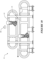
- the coloured particles are fed into a hopper having an opening for feeding the particles onto a roller rotating at a predetermined rate of rotation.
- the roller is mounted above a conveyor moving at a pre-determined speed.
- the substrate to be decorated is laid upon or deposited on the conveyor such that the exposed surface to be decorated is face up.
- the exposed surface to be decorated is conveyed under the roller and as the roller rotates the coloured particles fed onto the roller are applied to the exposed surface to be decorated.
- the colour particles are fed into a hopper for feeding the particles onto a roller mounted above a conveyor as described above and the particles are applied onto the surface of the conveyor as the roller rotates.
- the substrate to be decorated is then laid upon or deposited on the colour particles on the surface of the conveyor such that the exposed surface to be decorated is applied to the coloured particles.
- the amount of coloured particles brought into contact with the exposed surface to be decorated and/or the area, location, or position of the exposed surface to be decorate which the coloured particles are brought into contact with can be controlled by, for example, controlling the rate of rotation of the roller and/or the speed of the conveyor or various other commonly used methods for delivering particles, for example vibration.
- a vibrator is used to deliver the coloured particles at a predetermined rate to one or more predetermined areas of the exposed surface to be decorated.
- the one or more pluralities or coloured particles are be immobilised on the surface to which they are applied prior to applying the exposed surface to be decorated to the coloured particles.
- the coloured particles comprise charged particles.
- the particles are applied to an oppositely charged surface, such as a surface of a mold, to which the exposed surface of the substrate to be decorated is then applied.
- the coloured particles are applied to a permeable surface, such as a sieve having an aperture size smaller than the average particle size of the coloured particles, to which vacuum is applied prior to applying the exposed surface to be decorate to the coloured particles.
- a permeable surface such as a sieve having an aperture size smaller than the average particle size of the coloured particles
- the coloured particles are applied to a surface, such as mold, coated with an adhesive prior to applying the exposed surface to be decorated to the coloured particles.
- the coloured particles and/or surface to be decorated are exposed to a temperature and pressure sufficient to cause the coloured particles to fuse into or fuse to or coalesce with the exposed surface to be decorated, and the temperature and pressure are controlled over a period time to produce the substrate having a decorated surface.
- fusion or coalescence of the coloured particles and exposed surface to be decorated produces a decorated surface having continuous or unified polymeric matrix.
- the chemical composition of the polymeric matrix of the decorated surface will vary, for example between the coloured areas or regions provided on fusion on coalescence of the coloured particles and other areas or regions of the decorated surface.
- the one or more polymers of the particles and the one or more polymers of the exposed surface to be decorated may be the same or different. It will also be appreciated that in certain embodiments the continuous or unified polymeric matrix may comprise multiple polymeric phases, for example where decoration provides a polymer matrix comprising a compatible combination of polymers.
- fusion or coalescence of the coloured particles into, to, or with the surface to be decorated involves mutual interdiffusion and entanglement of polymer molecules of the one or more polymers of the exposed surface of the coloured particles and polymer molecules of the one or more polymers of the exposed surface to be decorated. Fusion or coalescence reduces the total interfacial area.
- various factors may affect fusion or coalescence, including for example the temperature and pressure and the molecular structure or morphology of the polymers involved, such as the molecular weight (MW) and molecular weight distribution.
- MW molecular weight
- polymer molecules having narrow molecular weight distributions and short chains of linear morphologies, such as certain polyethylenes may fuse or coalesce more readily than polymer molecules having long chains or complex morphologies.
- the coloured particles and/or surface to be decorated are exposed to a temperature sufficient to cause the coloured particles to fuse into or fuse to or coalesce with the exposed surface to be decorated at atmospheric pressure.
- the coloured particles and/or surface to be decorated may be exposed to pressure greater than atmospheric pressure.
- the temperature sufficient to cause the coloured particles to fuse into or to or coalesce with the exposed surface to be decorate may be lower than that required at atmospheric pressure.
- pressure may be applied to the coloured particles and exposed surface to be decorated. Applying pressure causes a mechanical interaction between the exposed surface to be decorated and the coloured particles which can promote fusion or coalescence and, depending on the pressure applied, may also reduce the temperature sufficient to cause fusion or coalescence. Accordingly, in some embodiments, the pressure applied at least partially embeds the coloured particles in the exposed surface to be decorated and/or causes the coloured particles to fuse into or fuse to or coalesce with the exposed surface to be decorated.
- Pressure may be applied by any suitable means.
- the substrate is conveyed on a conveyor with the exposed surface to decorated and coloured particles face up and pressure is applied to the particles and surface to be decorated using a roller mounted above the conveyor.
- the substrate is conveyed on a conveyor with the exposed surface and coloured particles face down in contact with surface of the conveyor and pressure is applied to using a roller to an opposing surface of the substrate.
- pressure is applied using a stamp (in a stamping process).
- the coloured particles and/or exposed surface to be decorated may be exposed to a temperature sufficient to cause fusion or coalescence at a given pressure by providing the coloured particles and/or exposed surface to be decorated at the desired temperature when bringing the particles and exposed surface to be decorated into contact; and/or heating the coloured particles and/or surface to be decorated to the desired temperature after bringing the coloured particles and exposed surface to be decorated into contact.
- Providing the coloured particles at the desired temperature may comprise heating the particles to a temperature at or above the desired temperature prior to bringing the particles and exposed surface to be decorated into contact.
- Providing the exposed surface to be decorated at the desired temperature may comprise heating the exposed surface to be decorated to or forming the exposed surface to be decorated at the desired temperature prior to bringing the particles and exposed surface to be decorated into contact.
- the temperature to which the coloured particles and/or the exposed surface to be decorated is heated or the exposed surface to be decorated is formed is above the desired temperature the coloured particles and/or exposed surface to be decorated may be cooled to the desired temperature prior to bringing the particles and exposed surface to be decorated into contact.
- Heat may be imparted to the coloured particles and/or the exposed surface to be decorated prior to or after bringing the particles and exposed surface to be decorated into contact by an external source of heat.
- heat may be imparted using an IR heater or an oven under or through which the particles and/or exposed surface to be decorated are conveyed.
- heat may be imparted by transferring heat from the coloured particles to the exposed surface to be decorated or from the exposed surface to be decorated to the coloured particles, on bringing the particles and exposed surface to be decorated into contact.
- heat may be imparted to coloured particles on bringing the particles into contact with a polymeric substrate following extrusion and/or molding which the substrate is still hot.
- the temperature and pressure sufficient to cause fusion or coalescence are controlled over a period of time to produce the decorated surface.
- the temperature and pressure may be controlled by any suitable method, for example a sequential or series of separately temperature controlled moulds or sections or regions of a moulding or a post-moulding process can be provided. In this way, the temperature of the substrate or surface of the substrate and the plurality of coloured particles can be controlled according to predetermined or desired processing conditions. It will be appreciated that the period of time for over which the temperature and pressure are controlled can vary depending on the processing conditions, materials used, and desired appearance of the decorated surface.
- the time over which the temperature and pressure are controlled can vary depending on the temperature and pressure employed. For example, where the coloured particles and/or exposed surface to decorated are exposed to a temperature and pressure significantly greater than that sufficient to cause fusion or coalescence is employed the time over which the temperature and pressure may need to be controlled may be less than that required in methods whether the temperature and pressure is not as great.
- the temperature to which the coloured particles and/or surface to be decorated are exposed to cause fusion or coalescence may be greater than the Tg of the coloured particles and/or one or more polymers of the exposed surface of the particles and/or greater than the Tg of the surface to be decorated and/or one or more polymers of the exposed surface to be decorated at the pressure to which the coloured particles and/or surface to be decorated are exposed. That is, the temperature to which the particles and surface to be decorated are exposed at the pressure employed may be greater than the Tg at that particular pressure.
- the temperature is typically at least 1°C greater than the Tg.
- the temperature may be at least 5°C greater, for example at least 10°C greater, preferably at least 50°C greater, than the Tg. Without wishing to be bound by theory, the inventors believe that such conditions promote fusion or coalescence of the coloured particles into, to, or with the surface to be decorated.
- the temperature to which the coloured particles and/or surface to be decorated are exposed to cause fusion or coalescence may vary depending on whether the one or more polymers of the particles or surface to be decorated are, for example amorphous or semi-crystalline.
- the temperature may for example be at least 100°C greater than the Tg of the polymer.
- the temperature may for example be greater than the Tg of the polymer by an amount that is at least half of the difference between Tg and Tm of the polymer.
- temperature and pressure sufficient to cause fusion or coalescence will depend on the one or more polymers of the exposed surface of the coloured particles and the one or more polymers of the exposed surface to be decorated. Suitable temperatures and pressures will be apparent to those skilled in the art in view of the present disclosure.
- the temperature to which the coloured particles and/or surface to be decorated are exposed to cause said coloured particles to fuse into or to or coalesce with said exposed surface may be at least 60°C. In some embodiments, the temperature to which the coloured particles and/or surface to be decorated are exposed to cause said coloured particles to fuse into or to or coalesce with said exposed surface is at least 100°C, for example at least 110, 120, 130, 140, 150, 160, 170, 180, 190, or 200°C or more.
- the pressure to which the coloured particles and/or surface to be decorated are exposed to cause said coloured particles to fuse into or to or coalesce with said exposed surface is at least about 2 bar, for example at least 3 or at least 4 bar, for example from 2 to 10, 3 to 10, or 4 to 10 bar.
- the amount of coloured particles brought into contact with the exposed surface to be decorated may vary across the width and/or length on of the exposed surface to be decorated to create a desired visual appearance.
- the coloured particles may be randomly distributed across the width and/or length of the exposed or distributed in an ordered arrangement, such as a pattern. Randomly distributed coloured particles may be useful for providing surfaces that resembles a natural material, such as stone or wood. Coloured particles may be dispensed from multiple dispensers configured or arranged to provide a desired appearance in or on the decorated surface.
- multiple pluralities of particles of the same or different type are sequentially or successively brought into contact with the surface to be decorated at the same area, location, or position of the surface to be decorated, thus depositing multiples layers of coloured particles on the surface to be decorated.
- Such selective decoration may reduce the amount of coloured particles used in the method, which can reduce costs.
- the coloured particles are selectively brought into contact with one or more predetermined areas of the exposed surface to be decorated. Such selectivity may be achieved by, for example, applying the coloured particles through a stencil and/or mask.
- the coloured particles brought into contact with the exposed surface to be decorated are selectively removed from one or more predetermined areas of the surface prior to fusion or coalescence of the particles.
- the coloured particles may be selectively removed by for example by brushing, blowing, vacuum, or adhesion to another surface. The removed particles may be subsequently recycled in the method, reducing costs. All or some of the coloured particles may be removed from the one or more predetermined areas, depending on for example the method of removal.
- the amount of coloured particles brought into contact with the exposed surface to be decorated may range from about 1 to 2,000 g/m 2 . It will be appreciated that the amount may depend on the density of the coloured particles.
- the percentage of the surface area of the exposed surface to be decorated that is brought in to contact with the coloured particles can range anywhere from about 1 to 100%.
- at least 50% or at least 60% of the surface area of the exposed surface to be decorated is brought into contact with (for example, covered with) coloured particles.
- the amount of coloured particles brought into contact with the exposed surface to be decorated may be controlled to control the degree to which the surface area of the decorated surface is coloured by colour provided by the coloured particles.
- the percentage of the surface area of the decorated surface that is coloured by colour provided by the coloured particles after causing the coloured particles to fuse into or to or coalesce with the exposed surface to be decorated can range anywhere from 1 to 100%, but is typically at least 5% or at least 10%.
- the MFI and/or HDT of the coloured particles and/or the one or more polymers of the exposed surface of the coloured particles, and/or the average particle size of the coloured particles can affect the extent to which the particles spread, diffuse, or run, etc. on fusion or coalescence into, to, or with the exposed surface to be decorated and thus affect the visual appearance of the decorated surface.
- the amount of coloured particles brought into contact with the exposed surface to be decorated, the percentage of the surface area of the exposed surface to be decorated that is brought into contact the coloured particles, and the percentage of the surface area of the decorated surface that is coloured by colour provided on fusion or coalescence of the coloured particles may vary depending on such characteristics.
- the decorated surface produced by the method of the present invention can vary in colour across the width and/or length of the surface.
- the variation in colour is not limited and may include variation in hue, saturation, or brightness, or a variation in reflectance, etc. In other embodiments, the variation in colour may additionally or alternatively include variation in transparency.
- the decorated surface comprises a plurality of visually differentiable coloured regions, which coloured regions may be the same or different in colour and/or size and/or shape, across the width and/or length of the surface.
- the boundaries between visually differentiable coloured regions in the decorated surface may be sharply or clearly defined or may be diffuse or poorly defined and may or may not overlap.
- the colour of each region may be uniform or may vary.
- the colour provided to the decorated surface by the coloured particles may extend into a portion of the depth of the substrate, for example when pressure is applied during the method that at least partially embeds the coloured particles in the surface.
- the colour across the width and/or length of the decorated surface may extend from the surface into a portion of the depth of the substrate but not penetrate the whole of the depth of the substrate.
- the colour may penetrate or extend into an upper portion of the depth of the substrate but not into a lower portion of the depth of the substrate.
- the substrate is a polymeric layer
- only an upper portion of the depth of the layer is coloured by colour provided by the coloured particles.
- the exposed surface to be decorated may be colourless or coloured.
- a coloured exposed surface to decorated may be uniformly or non-uniformly coloured in any colour (including blends or combinations of different colours) across the width and/or length of the surface.
- the exposed surface to be decorated may provide a background colour or combination of different background colours that contribute, for example by way of colour contrast, to the visual appearance of the decorated surface.
- the surface to be decorated may have an even or uneven topography.
- the exposed surface to be decorated comprises three dimensional surface features, including surface relief, surface texturing, or surface deformations, that contribute to the appearance of the decorated surface.
- Such uneven topography and three dimensional surface features may provide decorated surfaces that more closely resemble natural materials such as stone or wood.
- the decorated surface is subjected to one or more processing steps to introduce such three dimensional surface features to the decorated surface after production of the decorated surface.
- the decorated surface may be subjected to thermoforming and/or compression molding.
- the one or more pluralities of coloured particles and/or the surface to be decorated comprises one or more components susceptible to UV, thermal, and/or other environmental degradation.
- the visual appearance of the decorated surface may change as the substrate ages.
- the decorated surface may be subjected to one or more additional processing steps, for example stretching or otherwise or physically deforming the surface of the substrate. It will be appreciated that in some embodiments such additional processing steps may change the visual appearance of the decorated surface.
- the method of the present invention may provide a decorated surface having modified properties or performance characteristics, as well as a modified appearance, compared to the surface to be decorated.
- the decorated surface may have increased scratch or scuff resistance, UV performance, grip or slip resistance, surface hardness, etc.
- the decorated surface has increased surface hardness, scuff resistance, and/or slip resistance compared to the exposed surface to be decorated.
- the decorated surface may have a matt or glossy appearance or may comprise areas or regions of both.
- the coloured particles may provide the matt or glossy appearance to the decorated surface or preserve a matt or glossy appearance of a surface to be decorated.
- the method of the present invention can provide decorated surfaces of a range of different visual appearances.
- colour provided to the decorated surface by the coloured particles may appear to be "smeared" into or on the exposed surface, resulting in blurred or non-differentiated mineral-like appearance.
- the coloured particles provide a decorated surface having the appearance of discrete particles embedded in or on the surface (a granulated look). As described herein, in some embodiments such an appearance may be obtained using coloured particles of low MFI.
- the colour provided by the coloured particles runs together to provide a decorated surface having a blended or washed out appearance. As described herein, in some embodiments such an appearance may be obtained using coloured particles of meduim or high MFI.
- the present invention also relates to a substrate having a decorated surface produced by a method according to the present invention.
- the present invention also relates to a substrate having a decorated surface comprising one or more polymers and a plurality of coloured particles having an initial colour and comprising one or more polymers fused into or to or coalesced with said surface.
- the present invention also relates to a substrate having a decorated surface comprising a continuous or unified polymeric matrix comprising one or more polymers, said surface comprising a plurality of visually differentiable coloured regions, which coloured regions may be the same or different in colour and/or size and/shape, across the width and/or length of the surface.
- the colour of said coloured regions may extend from the surface to be decorated into a portion of the depth of the substrate but in some embodiments not the whole of the depth of the substrate.
- the substrate is a roofing, cladding, or siding product (including roofing, cladding, or siding modules), for installing onto a building surface or a coating or layer of a coating for a roofing, cladding, or siding product, such as those described in WO 2016/088026 , preferably a polymeric product, or a polymeric coating or polymeric layer of a coating.
- a roofing, cladding, or siding product including roofing, cladding, or siding modules
- a polymeric product or a polymeric coating or polymeric layer of a coating.
- polymeric products as described herein, may be formed of or consist or consist essentially of or comprise one or more polymeric layers, for example two or more, three or more, four or more, five or more, or six or more polymeric layers.
- roofing, cladding and siding products for installation onto building surfaces need to be lightweight, easy to install, weatherproof, resistant to environmental wear, aesthetically pleasing and preferably economical and efficient to manufacture.
- Polymeric materials are suitable candidates for roofing, cladding and siding products due to their weight, durability and cost-effectiveness.
- polymeric products need to be cosmetically treated to simulate the appearance of these more traditional products.
- Systems and methods for manufacturing these polymeric products need to be suitably flexible, in order to be able to simulate a variety of materials.
- the roofing, cladding and/or siding module contemplated herein has improved weather resistance (e.g., water resistance, hail-proofing), durability, fire resistance, flame retardant qualities and/or aesthetic qualities.
- the method of the present invention relates to manufacturing and decorating (or coloring) a roofing, cladding or siding module out of a polymeric material, such that the module resembles tiles, shingles, etc., made of another type of material.
- Preferred embodiments of the present invention relate to improved methods and systems for manufacturing a roofing, cladding or siding module in a high speed and/or cost-effective and/or efficient process.
- the module is formed of at least one layer formed of an extruded material, for example an extruded material comprising at least about 40%, for example at least 60%, w/w filler and/or reinforcement based on the total weight of the layer.
- an extruded material comprising at least about 40%, for example at least 60%, w/w filler and/or reinforcement based on the total weight of the layer.
- the substrate comprises a layer of a roofing, cladding, or siding module defining the exposed surface to be decorated, optionally wherein the layer is formed of an extruded material comprising filler and/or reinforcement, for example at least 1, 5, 10, 15, 20, 25, 30, 35, 40, 45, 50, 55, 60, 65, 70, 75, 80, 85, 90, or 90% w/w filler and/or reinforcement (and useful ranges may be selected from any two of these values), and one or more polymers.
- the substrate may further comprise one or more additional layers from which the module is formed.
- the substrate may comprise two or more, or three or more layers.
- Described herein are improved methods and systems for manufacturing such a roofing, cladding or siding module in a high speed and/or cost-effective and/or efficient process.
- continuous forming processes For example, described herein are continuous forming processes. Also described are modules manufactured using such processes. Larger areas and lengths of the module may be produced over a shorter duration of time compared to prior art methods such as injection, pressure, compression, or vacuum molding or thermoforming. It is envisaged that the continuous forming system of the present invention can produce approximately 1 to 60 m, such as 5 to 60 m, of product per minute. In one embodiment, the continuous forming system produces approximately 20 m of product per minute.
- a single moulding machine (e.g. may be continuous) may be utilised having a plurality (e.g. 2 or more) output tracks or lanes of as-molded products exiting from the machine. In this manner, a plurality of as-moulded products may be simultaneously formed.
- the continuous forming method of the present invention produces a module that lacks weld lines, attachments or injection moulding points along the entire length of the module.
- Weld lines are formed during injection molding processes when two or more molten polymer flows meet. This can occur when a polymer flow splits to go around an interruption (e.g., a post that forms a hole) and then rejoins, or when polymer melt fronts meet, from multiple injection points. This can also occur when molten polymer meets a non-molten polymer (e.g. segmented injection molding). Consequently, a visible weld line is observed and the adhesion/bond in this weld line at the interface is weaker than the balance of the polymer within the product.
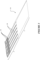
- the module 1 preferably comprises an underlapping region 2 extending from a head edge 4 of the module and an exposed region 3 extending from a foot edge 5 of the module.
- the underlapping region 2 is adapted to be substantially covered by the exposed region of an adjacent or overlapping module when installed on a building surface, as shown in Figure 5 .
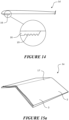
- the module may take a variety of forms, for example, several variations 1, 1a, 1b, 1c, 1d, 1e are shown in Figures 1 , 3 , 5 , 6 , 14 and 15 .
- the module preferably comprises an underlapping region extending from a head edge of the module and an exposed region extending from a foot edge of the module.
- the underlapping region is adapted to be substantially covered by the exposed region of an adjacent or overlapping module when installed on a building surface.
- the module may take a variety of forms.
- the module preferably has at least one layer which is formed of an extruded material comprising one or more polymers and at least 40% filler and/or reinforcement.
- Figure 4a shows a cross-sectional view of one embodiment of the module 1.
- the module comprises a single layer along a section of the module or along the entire length of the module.
- the layer is formed of an extruded material comprising at least about 40% w/w/ filler and/or reinforcement, more preferably at least about 60% w/w filler and/or reinforcement.
- At least a portion of the underlapping region 2 of the module is formed of the extruded material comprising at least about 40% w/w filler and/or reinforcement, more preferably at least about 60% w/w filler and/or reinforcement.
- the polymers of the extruded material may be selected from those described herein with respect to the one or more polymers of the exposed surface to be decorated.
- the one or more polymers of the extruded material are selected from thermoplastic polymers.
- the one or more polymers of the extruded material may comprise one or more elastomers.
- the one or more elastomers are selected from thermoplastic elastomers.
- the one or more elastomers increase the elasticity of the extruded material, allowing the material to give during thermal expansion and contraction.
- the ability of the material to expand in one or two dimensions may be more constrained compared to other dimensions, leading to a greater amount of thermal expansion in dimensions where expansion is unconstrained or less constrained.
- thermal expansion in the length of a module may be constrained, leading to increased expansion in the width and/or depth of the module.
- the inclusion of one or more elastomers increases ability of the extruded material to undergo thermal expansion (and contraction) in dimensions unconstrained or less constrained to thermal expansion without causing permanent damage to the structure of the material, for example stress, delamination, cyclic expansion/contraction fatigue, or otherwise compromising the structure of the material.
- One or more elastomers may be present in the layer defining the surface to be decorated. The presence of the one or more elastomers may affect the hardness of the layer.
- one or more layers of the module such as the layer defining the surface to be decorated, and/or the decorated surface has a Shore A hardness at least 60, for example at least about 65, 70, 75, 80, 85, or 90 (and useful ranges may be selected from any two of these values, for example, from about 60 to 90, 70 to 90, or 80 to 90); and a Shore D hardness of less than about 60, for example less than about 55, 50, 45, 40, 35, or 30 (and useful ranges may be selected from any two of these values, for example, from about 60 to 30, 50 to 30, or 40 to 30), any useful ranges may be selected from any Shore A and Shore D values (for example, a Shore A hardness of at least about 60 and a Shore D hardness less than about 60, or a Shore A hardness of at least 70 and a Shore D hardness less than 50). Both Shore A hardness and Shore D hardness may be determined by procedures in accordance with ASTM D2240-00.
- the extruded material comprises one or more of the following polymers: polystyrene (GPPS), polyethylene terephthalate (PET), polyester methacrylate (PEM), high impact polystyrene (HIPS), acrylonitrile butadiene styrene (ABS), polyvinyl chloride (PVC), polyurethanes (PU), polyethylene (PE) including homopolymer, copolymer, block copolymer and terpolymer forms, polylactic acid (PLA), nylon (PA), acrylics (PMMA), high density polyethylene (HDPE), low density polyethylene (LDPE), linear low density polyethylene (LLDPE), medium density polyethylene (MDPE), cross linked polyethylene (PEX), thermoplastic elastomer (TPE), thermoplastic polyolefin (TPO), thermoplastic rubber (TPR), polypropylene (PP) including homopolymer and copolymer forms, polybutylene terephthalate (PBT), styrene-acrylonit
- suitable fillers and reinforcements for the extruded material include those described herein.
- suitable fillers include any one or more of talc, calcium carbonate, mica, silica, kaolin, calcium sulphate, magnesium hydroxide, stabilizers, dolomite, etc.
- suitable reinforcements include any one or more of glass fibres, glass beads, glass flakes, natural fibres such as flax, cellulose, wood fibres, wood flour, cotton and sawdust, inorganic fibres, polymer fibres, polymer scrim, polymer knit, polymer weave, aramids, ceramics, etc.
- Fillers are added to the extruded material to reduce the amount of the more expensive polymer component, hence reducing the material cost.
- increasing the filler content tends to negatively affect the physical properties of the extruded material.
- prior art injection moulded products typically require relatively low filler content, otherwise the material does not flow to fill the dies and/or becomes too hard to be mouldable and/or the moulded product is unstable (e.g., may be poor melt flow or may be due to thermal expansion) or brittle.
- Prior art products compensate by adding a reinforcing scrim layer between layers of polymer; however, these are typically difficult and expensive to manufacture.
- the extruded material preferably comprises at least about 40% w/w filler and/or reinforcement, and preferably at least about 60% w/w filler and/or reinforcement. In some embodiments, the percentage of filler and/or reinforcement is between about 60% and 95% by weight of the extruded material.
- Provision of filler and/or reinforcement into a layer can provide for an increased weight or density or bulk (e.g. volume) of a layer so formed and thereby of a module made by at least one of such a layer.
- the extruded material comprises both filler and reinforcement. That is, at least 40% w/w of the extruded material comprises filler and reinforcement.
- the extruded material does not contain reinforcement. In some embodiments, the extruded material comprises at least about 5% w/w reinforcement (i.e., in this embodiment, the extruded material comprises at least about 55% w/w filler and at least about 5% w/w reinforcement). In some embodiments, the extruded material comprises between about 5% and 40% or 5% and 30% w/w reinforcement, for example about 5% to about 20% or about 10% or about 15% reinforcement.
- the reinforcement comprises or consists or consists essentially of fibers, for example one or more non-conductive natural or synthetic fibres, such as glass fibres, carbon fibres, polymer fibres, and the like.
- the reinforcement comprises or consists or consists essentially of glass fibres.
- typical dimensions of the glass fibre prior to processing may be between about 0.5 to 15 mm, 0.5 to 10 mm, or 0.5 and 5 mm in length (or may be about 1-15 mm, 1-10 mm, 1-5 mm, or about 2-5 mm, or about 3-5 mm in length) and about 0.015 to about 0.018 mm in diameter.
- the reinforcement may also reduce thermal expansion of the module, hence improving stability and durability of the module when exposed to cyclical variations in heat.
- the glass fibres align along the length of the module during the forming process. As a result, the module is particularly stable along its length (i.e., the longest dimension of the module, which typically undergoes greatest change in length due to thermal expansion).
- Fibres such as glass fibres
- Fibres may be aligned along the length of the module on extrusion of the extruded layer from an extruder and that alignment may be retained during the forming process. This alignment of fibres along the length of the module constrains thermal expansion along the length of the module, reducing the amount of thermal expansion along the length of the module and increasing thermal expansion along the width and depth of the module in which thermal expansion is unconstrained or less constrained.
- aligned and related terms, such as “align" as used herein with reference to the orientation of fibres in the module means that the fibres are substantially aligned in the direction indicated. That is, the fibers extend in length in a generally common direction with substantially increased orientation, compared to randomly aligned or oriented fibres. It should be understood that fibers may still be considered to be aligned even though a portion of the fibers may not be orientated in the generally common direction. It should also be understood that portions of certain fibers may bend curl, twist and/or the like in a non-aligned manner and that such fibers may still be considered to be aligned.
- At least about 55, 60, 65, 70, 75, 80, 85, 90, or 95%, of the fibres may be oriented or aligned generally in a common direction and/or at least about 55, 60, 65, 70, 75, or 80% of the linear length of at least a majority, for example more than 50, 55, 60, 65, 70, 75, or 80% of the fibres are oriented and/or aligned in a common direction.
- the extruded material comprises fibres as a reinforcement and one or more elastomers.
- the inclusion of one or more elastomers increases ability of the extruded material to thermally expand and contract, for example in dimensions unconstrained or less constrained that other dimensions of the module, without causing permanent damage to the structure of the material.
- the extruded material comprises at least about 5% w/w glass fibres, preferably at least about 10% w/w, for example at least about 15% w/w. In some embodiments, the extruded material comprises from about 5% to 20%, for example from about 10% to 20%, w/w glass fibres.
- Fibres such as glass fibres may break up during extrusion and/or other parts of the forming process, reducing their length. Processing parameters can be varied and/or optimised to reduce and/or minimise the amount by which the average length of the fibres is reduced during extrusion and/or forming, etc.
- the average length of the fibres in the layer formed from the extruded material may depend on, for example, the type of fibre, geometry of the extrusion screw, die configuration, melt pipe flow characteristics, where and how the fibres are fed or otherwise introduced into the extruder, etc. In one example, reduction in the average length of the fibres is reduced and/or minimised by avoiding the use of screen packs or other structures in the melt pipes that causes or increases the amount of turbulence on fibres in the melt.
- reduction in the average length of the fibres is reduced and/or minimised by feeding the fibres into the extruder at a zone in which the polymer is molten (compared to feeding the fibres in to the extruder at a zone, for example the primary feed end or cooler end of the extruder distal to (i.e. opposite to) the die, where the polymer is in a solid form, for example beads, pellets, etc,, which may crush the fibres as the material is pushed through the extruder).
- the layer formed from the extruded material comprises glass fibres having an average length of at least about 100 microns, for example at least about 150, 200, 250, 300, 350, 400, 450, 500, 550, 600, 650, 700, 750, 800, 850, 900, 950, or 1,000 microns.
- the layer formed from the extruded material comprises glass fibres having an average length from about 100 to 2000, 200 to 2000, 300 to 2000, or 400 to 2000 microns, for example 400 to 1500, 400 to 1000, 500 to 2000, 500 to 1500, 500 to 1000, 600 to 2000, 600 to 1500, 600 to 1000 microns. Having glass fibres of such a length in the layer after forming may allow the amount of glass fibres in the layer to be reduced without increasing the amount of thermal expansion.
- Table A compares the thermal expansion coefficient of three test samples: a) polymer (TPO) with no filler and no reinforcement, b) exemplary prior art product comprising a layer of reinforcing (polyester) scrim encapsulated between top and bottom TPO layers, the TPO layers comprising 40% w/w filler, and c) one embodiment of the present invention comprising polymer (TPO) with 80% w/w filler and 10% w/w reinforcement.
- heat was applied to the test sample to raise the temperature of the sample by about 80°C from ambient temperature. The dimensions of each sample were measured at initial (ambient) temperature of about 14°C and again at the final elevated temperature of about 94°C to determine the thermal expansion.
- Such embodiments of the present invention demonstrate much less thermal expansion, compared to pure polymer. Such embodiments instead undergo minimal thermal expansion that is comparable to polymer reinforced with a scrim layer, but does not suffer from the manufacturing challenges associated with the prior art product.
- Table A Thermal expansion coefficient of test samples with differing levels of filler. Polymer % filler % reinforcement Thermal expansion coefficient (10 -6 m/(m K)) TPO 0 0 165 TPO with reinforcing scrim 40 0 10 TPO 80 10 22
- the layer of the module is tough, heat-stable, dimensionally stable, and low cost (in particular due to the high filler content).
- module is preferably manufactured in a single continuous forming process (described in more detail below). It is envisaged that module may be formed in lengths of at least about 0.25 m, for example 0.3 m or 0.5 m. Alternatively, the module may be formed in lengths of about 36 inches long. Alternatively, the module may be formed in lengths of at least about 1 m, 1,5 m, 2 m, 2.5 m, 3 m, or any numerical value in between.
- the surface of the module exposed when installed is of a length of at least about 1 m or 36 inches.
- the ratio of the planar cross sectional area of the underlapping region to the planar cross sectional area of the exposed region is from about 2:1 to about 1:2, for example 1.5:1 to 1:1.5, 1.5:1 to 1:1, or 1.2:1 to 1:1, preferably about 1.2:1.
- the ratio of the planar cross sectional area of the underlapping region to the planar cross sectional area of the exposed region is from about 10:90 to about 1:99, for example 5:95.
- moulding the entire length of the module in a continuous process eliminates any weld lines. This increases the durability and weather resistance of the modules, and improves the appearance of the final product.
- the extruded material may further comprise one or more of the following additives: colorants (including but not limited to carbon black, titanium dioxide), flame retardants (including but not limited to magnesium hydroxide, aluminum trihydrate), stabilizers (including but not limited to UV light stabilizers such as hindered amine light stabilizers (HALS), and thermal stabilizers such as phenolics), foaming agents (including but not limited to exothermic, endothermic or gas foaming agents), lubricants, and/or biocides (including but not limited to particles of silver, including nano-sized silver particles).
- colorants including but not limited to carbon black, titanium dioxide
- flame retardants including but not limited to magnesium hydroxide, aluminum trihydrate
- stabilizers including but not limited to UV light stabilizers such as hindered amine light stabilizers (HALS), and thermal stabilizers such as phenolics
- foaming agents including but not limited to exothermic, endothermic or gas foaming agents
- lubricants including nano-sized silver particles.
- Figure 4b shows a cross-sectional view of a second embodiment of the module 1.
- the module comprises two layers along a section of the module or along the entire length of the module.
- the base or bottom layer 8 is formed of an extruded material comprising at least 60% filler and at least 5% reinforcement.
- the top layer 6 or both layers is/are formed of an extruded material comprising at least 60% filler and at least 5% reinforcement. That is, the percentages and/or material of the polymer(s) and/or filler and/or reinforcement may be the same or different in each layer.
- the material content of each layer is preferably selected to suit the function, appearance and/or exposure of the particular layer.
- Figure 4c shows a cross-sectional view of a third embodiment of the module 1.
- the module has at least one portion 10 which comprises at least three layers: a top layer 6, a bottom layer 8, and an intermediate layer 7 between the top and bottom layers.
- the module may be formed from more than three layers, for example if more than one layer of material forms a precursor to the top layer, intermediate layer and/or bottom layer.
- said layer formed of said extruded material is provided as a base or bottom layer and the module further comprises one or more additional upper layers provided as further layers upon said base or bottom layer.
- said one or more upper layers comprise a different filler and/or reinforcement content relative the base or bottom layer.
- said one or more upper layers comprise the same filler and/or reinforcement content relative the base or bottom layer.
- a top layer comprises thermoplastic olefin (TPO).
- Two or more layers may be extruded or coextruded to form the or at least a part of the module.
- the two or more layers may be joined in a continuous forming process to form the or at least a part of said module.
- At least a portion of the module comprises a top layer (or an upper layer or a plurality of upper layers forming a said top layer), a base or bottom layer (or a lower layer or a plurality of lower layers forming a said base or bottom layer), and an intermediate layer (or a plurality of layers forming a said intermediate layer) between the top and base or bottom layers.
- At least one layer is formed of an extruded material comprising at least 40% filler and/or reinforcement, preferably at least 60% filler and/or reinforcement.
- the module may further comprise one or more additional layers formed of material that may comprise less than 40% filler and/or reinforcement.
- the at least one layer formed of an extruded material comprising at least 40% filler and/or reinforcement is a base or bottom layer that substantially contributes to the structure of the module.
- this base or bottom layer is formed of an extruded material comprising at least 60% filler and at least 5% reinforcement.
- the base or bottom layer comprises about 80% to 85% w/w filler and/or reinforcement, more specifically, about 70% to 75% filler and about 10% w/w reinforcement.
- a base or bottom layer may have a thickness of about 1-3mm.
- the resulting layer(s) may provide resistance against significant thermal expansion of the module, which in turn may help reduce shear forces between layers and/or other structures attached to the module that may be due to thermal expansion of those other layers.
- the structural layer(s) may be provided as one or more intermediate and/or upper layer(s).
- the upper or top layer(s) 6 and/or the intermediate layer(s) 7 and/or two or more layers may also be formed of an extruded material comprising at least 60% filler and/or reinforcement.
- the extruded material comprises at least 5% reinforcement.
- the material of the matrix and/or filler and/or reinforcement may be the same or different in each layer.
- the top layer 6 may comprise at least 65% filler, and no reinforcement.
- the higher polymer content may be suitable for the top layer, e.g., to facilitate binding of colored particles (as described in more detail below).
- such a top layer may have a thickness of about 0.4mm.
- the top layer 6 may comprise at least 65% filler and reinforcement.
- the intermediate layer may comprise about 100% polymer (i.e., the intermediate layer may not comprise filler or reinforcement), which may increase one or more particular reinforcing properties of the layer, such as waterproofing.
- the intermediate layer may comprise a polypropylene copolymer reinforced with a copolymer polyethylene.
- the reinforcing polymer may comprise up to about 50% w/w of the layer, preferably between 10% and 25% w/w of the layer.
- such an intermediate layer may have a thickness of about 0.5mm.
- a multi-layered module may be formed using at least the top layer, the intermediate layer and the base or bottom layer as described above.
- one or more of the layers may comprise(s) three-dimensional features such as surface texturing, surface relief or other three-dimensional pattern or ornamentation.
- Figure 1 schematically shows surface texturing on the exposed regions 3 of the module 1 (i.e., the surface is not smooth), to simulate asphalt shingles.
- At least a portion of the exposed region 3 of the module has three-dimensional surface features. Accordingly, in the multi-layered embodiments shown in Figure 4b , at least a portion of the upper surface of the top layer, corresponding to the exposed region in the finished module, may have three-dimensional surface features.
- the module may additionally or alternatively comprise two or three dimensional surface features such as coloring, patterning, surface cracking or fracturing or other two- or three-dimensional decoration or ornamentation.
- These three dimensional and/or two dimensional (e.g. flat) surface features are preferably provided on at least the exposed region 3 of the module, in order to simulate another type of natural or manufactured material, including but not limited to asphalt shingles, slate, timber shingles or shakes, concrete tiles, stone chips, weatherboard, thatch, stone, woodgrain, metal (e.g., copper tiles), etc.
- the module comprises at least three layers at the exposed and fastening regions.
- the top layer 6 provides the cosmetic finish on the exposed region of the module, and preferably includes surface features on the top surface as described above.
- the intermediate layer 7 may provide reduced thermal expansion, additional reinforcement, water or weather resistance and/or a binding layer between the top and bottom layers.
- the bottom layer 8 forms the base structure of the module and therefore preferably extends throughout the entire width and length of the module.
- the bottom surface of the bottom layer at the exposed region further includes projections (e.g., ribs) that provide adhesion surfaces, as described in more detail below.
- the module may comprise three layers in any arrangement, and across any region of the module. Exemplary embodiments are shown in Figures 13a-13h .
- the module comprises at least two layers at the exposed and/or fastening region(s).
- the top layer 6 may provide the cosmetic finish on the exposed region of the module, and preferably includes surface features on the top surface as described above.
- the base or bottom layer 8 may provide the base structure for the module, and may be reinforced.
- the bottom surface of the base layer 8 may further includes projections (e.g., ribs) that provide adhesion surfaces, as described in more detail below.
- the layer may have a cosmetic finish (e.g. surface color added) on the exposed region of the module, and preferably includes surface features on the top surface as described above.
- the layer may also provide structural support for the module, and may likewise be reinforced (e.g., with reinforcement additives, surface treatment, surface features such as projections, etc.).
- one or more of the layers may be extruded. If two or more layers are extruded, they may be co-extruded.
- the layers may be extruded in series from two or more serially arranged extruders 20a, 20b, 20c, as shown in Figure 9 .
- a first extruded layer is deposited onto an advancing support surface of a continuous forming machine 11, and subsequently the other extruded layer(s) is/are deposited on top of the first layer.
- the layers then proceed as a layered feed to be molded between the first forming surface 12 and second forming surface 13, preferably as described below.
- one or more of the layers may be molded by thermoforming, compression moulding, pressing or other method of forming.
- the layers are subsequently joined together preferably by the continuous forming machine 11 as described below.
- the layers are joined or laminated together to form the module in a continuous forming process (described in more detail below).
- the layers and/or their content, such as the polymer(s) is/are selected to be compatible with each other, to ensure adequate joining/fusing between each layer.
- the preferred forming process allows for multiple layers in various configurations (e.g., varying continuity, material properties, etc) to be joined together to form the finished module. Referring to the cross-sectional view of one example of the module shown in Figure 4c , in a preferred embodiment of the present invention, one or more properties of the intermediate layer 7 varies along the length and/or width of this layer.
- the thickness of the intermediate layer 7 varies along its width. Specifically, the intermediate layer is thinner near the foot edge 5 of the module, and increases in thickness towards the middle of the module. As will be discussed in more detail below, this thicker portion preferably coincides with the fastening region of the module.
- the reinforcing layer 7 may be formed above or below the top or bottom layer of the module respectively.
- the reinforcing layer may be present intermediate the head edge 4 and foot edge 5 of the module, or may extend to one or both of the edges.
- the intermediate layer (where present) may be between 0.01 and 10 mm thick, whether of a constant thickness throughout, or whether the thickness varies as discussed above.
- the intermediate layer may be between 0.1 and 0.5 mm thick; or may be any numerical value between 0.01 and 10 mm.
- the top and bottom layers may each be between 0.1 and 50 mm thick, whether the thickness is constant or varying across each layer.
- the top layer is between 0.1 to about 10 mm thick.
- the top layer is about 0.05, 0.1, 0.2, 0.3, 0.4, 0.5, 0.6, 0.7, 0.8, 0.9 mm thick, or may be numerical values between each of these.
- the bottom layer is about 0.1 to about 10 mm thick.
- is the bottom layer about 0.5, 1, 2, 3, 4, 5, 6, 7, 8, 9 mm thick, or may be numerical values between each of these.
- the varying property of the intermediate layer could be a change in surface area of the intermediate layer, for example by corrugating (or changing the degree of corrugations on) a portion of the intermediate layer.
- Additional or alternative properties of the intermediate layer which may be varied along the length or width of the layer include tensile strength, shear strength, resilience, elasticity, flexibility, toughness, fire resistance, water resistance, continuity or uniformity, water-proofing, impact resistance, resistance to pull through, fixing capability, chemical resistance, puncture resistance, content of filler and/or reinforcement, concentration of filler and/or reinforcement, color, microbial resistance, temperature resistance, light/heat absorption/reflectivity, thermal transfer, shape memory, thermal expansion, grip, abrasion or scuff resistance, slip resistance, adhesion/gluing/bonding capability, sealing ability etc., of the layer.
- continuity and uniformity there may be areas where the intermediate layer is not present in the module, such that the intermediate layer is discontinuous across the length and/or width of the module.
- one or more property/properties of the other layers may additionally or alternatively vary along the length and/or width of the layer.
- the surface area of the intermediate layer may be varied by changing the properties of three-dimensional surface features on the intermediate layer.
- the intermediate layer may have three-dimensional surface texturing, or other projections, corrugations, reinforcements, chemical coatings, protrusions, apertures, perforations, 3D replications of natural surface, water repelling features (features to assist with water repelling) or surface roughness which increase the mechanical bonding of this layer to the top and/or bottom layers.
- any one of the layers may be pre-formed (e.g., by extrusion, or other type of forming process) and subsequently introduced to the forming/lamination process to form the module.
- the layer may be heated or reheated so that it is in a molten or pliable state when fed to the forming/laminating machine.
- the height or width of the surface features may vary along one or more directions of the layer, or in specific areas of the layer.
- the number of surface features i.e., the concentration of surface features per unit length or width of the layer
- the variation in the property/properties of the intermediate layer may be caused by deforming the intermediate layer before or during joining or laminating to the top and/or bottom layers. For example, by stretching a localized portion of the intermediate layer while it is still in a molten, semi-molten or pliable state, the concentration of surface features within this region may be reduced. Accordingly, the mechanical bond strength at this region would be weaker compared to other non-deformed regions, or preferentially reduced to provide for desired mechanical properties of the intermediate layer and its reinforcement of the associated upper and lower layers.
- the intermediate layer is a reinforcing layer (e.g., a reinforcing film, mesh, scrim, weave, fibre, fabric, wire, string, web or sheet) between the top and bottom layers.
- the intermediate reinforcing layer preferably provides for one or more of: resistance against shrinkage, resistance against warping, resistance against tearing, increased toughness, prevention against unwanted deflections of the module, weather or water resistance, reduced flammability, impact resistance, resistance to pull through (e.g., of fasteners due to high winds), fixing capability, chemical resistance, puncture resistance, sealing (e.g., self-sealing around fasteners), shape memory and increased resistance against delamination of the layers, adhesive/gluing/bonding capability, thermal expansion (or contraction), surface texture, binding of other materials, etc.
- the pull through strength of the module is preferably at least as required in the standard specification for asphalt shingles made from glass felt and surfaced with mineral granules (ASTM D3462).
- the standard specifies that when pulling a nail head through the shingle at 100mm/min, the pull through force is at least 90 N. Accordingly, the nail pull through force demonstrated by the present module is at least about 90 N, more preferably at least about 100 N, and may be more than 130 N.
- the intermediate layer may provide a substantially water or liquid resistant barrier, or a water or liquid impermeable barrier between the top and bottom layers. This is particularly advantageous where the top or bottom layers are porous.
- the top layer of the module may be fractured or otherwise crazed to provide surface ornamentation for simulating another type of material.
- the intermediate layer preferably provides a substantially waterproof barrier below this top surface, at least at the porous region(s).
- the reinforcing properties of the intermediate layer may vary depending on the requirements at different sections of the module. At zones of increased exposure or under increased loading, for example, the reinforcing properties of the intermediate layer may be increased, but at other sections, may be reduced to reduce the amount of material used.
- the module may further comprise a fastening region 14 for receiving one or more fasteners that fix the module to the building surface when installed.
- the fastening region may be substantially adjacent the exposed region 3 and within the underlapping region 2.
- the fastening region may include a visual guide or boundary markers to allow visual identification of the region.
- the fasteners may be nails, screws, etc, which puncture or penetrate the module when installed.
- the intermediate layer may extend from at or adjacent the foot edge 5 of the module to within or beyond the fastening region 14 of the module.
- the intermediate layer may be present only along the fastening region 14 of the module.
- the intermediate layer may extend from at or adjacent the foot edge, to at or adjacent the underlapping region of the module. That is, the intermediate layer may provide for additional reinforcement and/or weather resistance throughout the exposed region of the module.
- the module may comprise more than one intermediate layer.
- the two or more intermediate layers may comprise the same or different material and/or may perform the same or different functions.
- the layers may be present as discrete intermediate layers in different regions of the module or there may be multiple intermediate layers in one or more regions of the module. For example, there may be two intermediate layers in the fastening region, one providing a waterproofing function, the other providing self-sealing properties around fasteners.
- the reinforcing property/properties of the intermediate layer may be optimized preferentially within this fastening region 14, to increase the toughness and tear-resistance of the module at this layer. Additionally, the reinforcing property/properties of the intermediate layer may also be increased within the exposed region of the module.
- the intermediate layer may be thicker along the fastening region, compared to within the exposed region.
- the intermediate layer may comprise thickened regions or other 3-dimensional qualities within the fastening region 14, which provide for a fastening region capable of retaining a fastener penetrating the fastening region or resisting tear or pull through of the module by shear force applied to the module or each of the said layers by the fastener.
- the reinforcing property/properties of the intermediate layer may be optimized preferentially along the direction of the length of the module and/or along the direction of the width of the module. It will be appreciated that the direction and/or regions of optimizing or increasing the reinforcing properties of the intermediate layer will depend on the structural requirements (e.g., the amount of loading, shear force, tensile force, strain, etc., along that direction or within that region) of the module when installed.
- variations in these properties may be achieved when forming the intermediate layer, whether by extrusion or other forming processes. These variations may additionally or alternatively be achieved by deforming (e.g., stretching) the intermediate layer when it is being joined to the top and/or bottom layers, and is in a molten or semi-molten moldable state.
- the intermediate layer when being joined to the top and/or bottom layers, is preferably in a molten or semi-molten state, or a cold but pliable, formable or moldable condition. In this state, the intermediate layer is able to be deformed with little or no localized areas of high stress.
- the intermediate layer may form chemical bonds with compatible material(s) in the top and/or bottom layer.
- the intermediate layer may be inserted between molten or semi-molten top and bottom layers, and may therefore form chemical bonds with these layers.
- the module may be shaped and/or contoured during the joining/laminating process, while the intermediate layer is in the cold but pliable or molten or semi-molten moldable state. This ensures that the intermediate layer remains substantially aligned and/or substantially consistently positioned between the top and bottom layers through the shape and/or contour. This is shown in the detailed views of Figures 7 and 8 .
- the module may be shaped and/or contoured via a casting, thermoforming, pressing or other forming process, whether continuous or discontinuous, during or after the joining/laminating process.
- all three layers of the module are in a molten, semi-molten, cold but pliable, formable or moldable condition when being joined together. This may further increase the strength of the chemical bond between compatible materials in each layer. This may additionally reduce the occurrence of localized high stress points in the module, whether or not the module is further shaped after joining the layers.
- the material for each of the layers is preferably chosen to have a melt flow index and/or heat capacity sufficiently high such that the layer(s) remain molten or semi-molten or pliable while the module is formed.
- the layers are processed at a sufficiently high temperature such that the layers remain molten or semi-molten or pliable while the module is formed.
- the layers are each made of, or comprise, one or more polymer(s).
- Materials which may be used include (but are not limited to) general purpose polystyrene (GPPS), polyethylene terephthalate (PET), polyester methacrylate (PEM), high impact polystyrene (HIPS), acrylonitrile butadiene styrene (ABS), polyvinyl chloride (PVC), polyurethanes (PU), polyethylene (PE) including homopolymer, copolymer, block copolymer and terpolymer forms, polylactic acid (PLA), nylon (PA), acrylics (PMMA), high density polyethylene (HDPE), low density polyethylene (LDPE), linear low density polyethylene (LLDPE), medium density polyethylene (MDPE), cross linked polyethylene (PEX), thermoplastic elastomer (TPE), thermoplastic polyolefin (TPO), thermoplastic rubber (TPR), polypropylene (PP) including homopolymer and copolymer forms, Polybuty
- any one or more of the layers of the module may comprise one or more additives, such as fillers (including but not limited to talc, calcium carbonate, mica, silica, kaolin, calcium sulphate, magnesium hydroxide, stabilizers, dolomite); colorants (including but not limited to carbon black, titanium dioxide); reinforcements (including but not limited to glass fibres, glass beads, glass flakes, natural fibres such as flax, cellulose, wood fibres, wood flour, cotton, sawdust, and inorganic or polymer fibres, scrim, knits, weave, non-woven, aramids, ceramics); flame retardants (including but not limited to magnesium hydroxide, aluminum trihydrate); stabilizers (including but not limited to UV light stabilizers such as hindered amine light stabilizers (HALS), and thermal stabilizers such as phenolics); foaming agents (including but not limited to exothermic, endothermic or gas foaming agents and liquid foaming agents); lubricants; and/or biocides (including but not
- one or more layers of the module may comprise one or more foaming agents (including but not limited to exothermic, endothermic or gas foaming agents and liquid foaming agents).
- foaming agents including but not limited to exothermic, endothermic or gas foaming agents and liquid foaming agents.
- the top layer preferably has a high UV resistance.
- the module is preferably configured and materials preferably chosen to withstand cyclical variations in temperature, for example, about -40 to about 100 degrees Celsius.
- the polymer(s) of the top and bottom layers has/have a lower degree of crystallinity compared to the polymer(s) of the intermediate layer. That is, the intermediate layer comprises a tougher, more crystalline polymer or polymer blend compared to the top and bottom layers.
- the top and bottom layers may comprise an amorphous polymer, or a polymer which is less crystalline compared to the intermediate layer.
- the intermediate layer may comprise polypropylene (PP).
- the top and/or bottom layers may comprise thermoplastic polyolefin (TPO), which is less crystalline or has fewer crystalline regions compared to polypropylene (PP).
- TPO thermoplastic polyolefin
- the polymer(s) of the top and bottom layers has/have a higher degree of crystallinity compared to the polymer(s) of the intermediate layer.
- the layers may each have any degree of crystallinity compared to each other.
- At least one layer or each or all of the layers comprises an amorphous polymer, or a polymer having a degree of crystallinity that is low, for example a degree of crystallinity of less than about 70, 65, 60, 55, 50, 45, 40, 35, 30, 25, 20, 15, or 10%.
- at least one layer or each or all of the layers comprises an amorphous polymer, or a polymer having a degree of crystallinity that for the given polymer is low.
- Some polymers are inherently more crystalline than other polymers. For example, HDPE may have a degree of crystallinity of about 70-80%, whereas LDPE may have a degree of crystallinity of about 45-55%.
- an HDPE having a degree of crystallinity of 70% has a degree of crystallinity that is low for an HDPE
- a degree of crystallinity of 20% has a degree of crystallinity that is low for an LDPE.
- the relative crystallinity of the layers may be achieved during manufacture of each layer, for example by controlling the temperature, rate of cooling, rate of extrusion, shear forces, or other factors as known in the art.
- the top and bottom layers may substantially thermally insulate or encapsulate the intermediate layer, so that the intermediate layer remains molten or semi-molten or pliable during the forming process. This controls the amount and/or rate of shrinkage of the crystalline or semi-crystalline intermediate layer throughout the cooling process, reducing warping in the module.
- the top and bottom layers may also substantially transfer or provide heat to the intermediate layer, to promote or maintain its molten or semi-molten or pliable state.
- the intermediate layer may also provide a binder layer for binding materials in the top and/or bottom layer together to form the module.
- the top layer may comprise sections of non-homogenous and/or non-compatible materials in order to achieve a particular surface texture or appearance simulating another type of material.
- the intermediate layer may be chosen to comprise a material which is compatible with each of the materials in the top layer. The intermediate layer therefore binds to each of the discontinuous sections of the top layer, effectively acting as a binder for binding these sections together.
- the module need not comprise three layers throughout the entire unit of module.
- the module may comprise a single layer or double layers throughout, or at specific regions, as described previously.
- the top and/or bottom layer may be foamed. This additionally reduces the weight of the module.
- the bottom layer 8 is made of a foamed polymer, such as foamed thermoplastic polyolefin (TPO).
- the module comprises a layer that provides for chemical resistance and/or a barrier that prevents and/or reduces migration of solvents and/or other chemicals through the layer to adjacent layer(s) of the module, for example from the underside of the module and/or from one more layers disposed beneath the chemical resistance and/or barrier layer to layer(s) disposed above, such as a top layer of the module.
- the chemical resistance and/or barrier layer is an intermediate layer of the module. In other embodiments, the chemical resistance and/or barrier layer is a base or bottom layer of the module.
- the migration of solvents and other chemicals, such as sealants, adhesives, or other construction materials, etc., into the top layer or top layers of the module can cause surface blooming and/or degradation and/or destabilization of polymer, which in turn can cause defects in this layer or layers of the module, such as visible deformation, delamination, warping, blistering, cracking, etc.
- the chemical resistance and/or barrier layer thus prevents and/or reduces such defects.
- the chemical resistance and/or barrier layer may be colorless or coloured, for example the same or similar color as the base colour of the top layer(s) of the module.
- the chemical resistance and/or barrier layer may have a low coefficient of thermal expansion and/or a coefficient of thermal expansion similar to one or more other layers of the module, preferably adjacent layer(s), such that it does not cause the module to warp or otherwise distort on heating or cooling.
- the chemical resistance and/or barrier layer has properties (for example, a Vicat softening point and/or HDT) such that it does not crack during handling, installation, or thermal expansion.
- the chemical resistance and/or barrier layer comprises one or more polymers. Suitable polymers will be apparent to those skilled in the art and include but are not limited to waterborne resins, solvent borne resins, radiation curable resins, powder coatings, alkyd, epoxy, urethane, acrylamid, or phenolic resins, and the like.
- the chemical resistance and/or barrier layer is comprises one or more UV curable acrylic.
- the chemical resistance and/or barrier layer comprises one or more polyolefin.
- the one or more polymers may provide the chemical resistance and/or barrier layer with properties such as flexibility, adhesion, and ability to "wet-out" or high surface tension and high flow rate, for example to provide acceptable coverage on application to another layer of the module.
- the chemical resistance and/or barrier layer may also comprise one or more additives as described herein.
- additives include but are not limited to fillers, adhesion promoters, wetting agents, levelling additives, pigments, foam control agents, rheology modifier, coalescent, solvents, diluents, dispersants, matting agents, crosslinking agents, and the like.
- the chemical resistance and/or barrier layer preferably extends across at least a portion, preferably the substantially the whole, of the length and width of the exposed region of the module.
- the barrier also extends across a portion of the length and width of the underlapping region.
- the barrier layer may extend across only a portion but not the whole of the length and width of the underlapping region of the module, as this region is adapted to be substantially covered by the exposed region of an adjacent or overlapping module when installed on a building surface.
- the chemical resistance and/or barrier layer does not extend across any of the width or length of the underlapping region of the module.
- the chemical resistance and/or barrier layer may be formed by any suitable method, for example extrusion, spraying, painting, curtain coating, transfer coating, vapour deposition, plasma coating, etc.
- the chemical resistance and/or barrier layer may be formed on or joined or laminated to one or more other layer(s) of the module before the module is formed or may be formed on or joined or laminated to a layer of the module after the module has been formed.
- the method employed is preferably capable of coating of the chemical resistance and/or barrier layer on a surface having three-dimensional surface features.
- the chemical resistance layer and/or barrier layer is formed by a method comprising applying a curable material to a layer of the module and curing the curable material, for example using UV radiation, heat, etc.
- the curable material may be applied spraying.
- the curable material is applied to a layer of the module before the layer is joined or laminated to one or more other layers of the module to form the module. In other embodiments, the curable material is applied to a layer of the module and cured as a post-treatment of a module after the module has been formed. In some of such embodiments, the chemical resistance and/or barrier may form a base or bottom layer of the module.
- the chemical resistance and/or barrier layer is formed by a method comprising extrusion or co-extrusion with one or more other layers of the module.
- One or more additional layers may be joined or laminated to the chemical resistance and/or barrier layer.
- an adhesive layer such as one or more continuous or discontinuous strips of adhesive (optionally which may be exposed upon removal of a release sheet) may be joined or laminated to the chemical resistance and/or barrier layer.
- the chemical resistance and/or barrier layer is, for example after curing, subjected to a plasma or corona treatment or other treatment that improves adhesion of the layer to one or more other layers to be joined.
- the one or more layers to be joined is an adhesive layer, such as one or more continuous or discontinuous strip of adhesive (optionally which may be exposed upon removal of a release sheet).
- the plasma or corona treatment or other treatment that improves adhesion creates stronger adhesion or bonding between the chemical resistance and/or barrier layer and the adhesive layer than between the adhesive layer and release sheet, thus facilitating removal of the release sheets from the adhesive layer without delamination or peeling of the adhesive layer from the chemical resistance and/or barrier layer.
- the surface of the release sheet in contact with the adhesive comprises a surface coating that reduces surface tension, for example a Teflon coating.
- the module may comprise one or more anti-scuff or protective layers on a top surface of the module, to protect at least the exposed region of the module during storage, transport and installation.
- the layer may be applied as an integral layer, or may be removably provided as a release sheet (to be removed after installation).
- the anti-scuff layer may be a layer of substantially virgin polymer, or a layer or coating comprising polymer or other suitable materials.
- the module may comprise one or more side laps for lapping under an adjacent module, to increase water resistance between adjacent modules.
- the side lap may be thinner, and/or may comprise fewer layers than other portions of the module. Side laps can provide for regions upon which adjacent modules may overlap with another module.
- the under surface of the layer may comprise projections instead of being a solid, continuous surface.
- the projections provide surfaces upon which the exposed region of the module may be adhered to the top surface of the underlapping region of an adjacent and/or overlapping module when installed.
- the projections provide sufficient adhesive surface area over discrete regions of the base, instead of a solid continuous surface, which would be more affected by shrinkage or thermal expansion/contraction, causing issues with adhesion.
- the projections further provide the required strength and rigidity of the layer, while reducing the weight of the layer.
- the projections comprise one or more longitudinal ribs 15 or other formations extending along the length of the module.
- Each longitudinal rib 15 may be continuous or discontinuous throughout its length, but preferably provides sufficient coverage of the module to provide sufficient adhesion surfaces. More preferably, the longitudinal rib extends through the entire length of the module, in order to provide sufficient strength along the length, and prevent warping along the length.
- the longitudinal ribs 15 extend substantially parallel to the foot edge 5 of the module.
- the longitudinal rib 15 may extend along a direction which is not parallel to the foot edge (e.g., the rib(s) may extend(s) diagonally across the module), but the rib preferably still extends along a substantial portion of the length of the module.
- the ribs are positioned near the foot edge 5 of the module, so that this edge of the exposed region of the module be adhered to the top of the adjacent or overlapping module, and may sit flush on the top surface.
- the module may also be formed with a convex precamber perpendicular to the length of the module, such that the exposed region is curved downwardly of the underlapping region.
- This pre-load pressure encourages the projections/ribs to contact firmly onto the underlapping panel when installed on the building surface.
- each longitudinal rib 15 there are a plurality of longitudinal ribs 15 (e.g., three ribs), extending substantially parallel to each other and spaced approximately 1 to 100 mm (preferably 1 to 10 mm) apart from each other.
- the height of the, or each, longitudinal rib may be between 1 and 100 mm (preferably, between 1 and 10 mm).
- the or each longitudinal rib may be between 1 and 1000 mm wide (preferably between 1 and 10 mm wide, or sufficiently wide to provide surfaces for adhering the module to the top of an adjacent or overlapping module when installed.
- the under surface of the bottom layer may further comprise a plurality of transverse ribs 16.
- These transverse ribs 16 may extend substantially perpendicular to the longitudinal ribs 15 and/or perpendicular to the length of the module.
- the transverse ribs may extend along any other direction, but preferably still extends along a substantial portion of the width of at least the exposed region of the module.
- transverse ribs may provide adhesion surfaces in addition to, or alternatively to the longitudinal ribs.
- the transverse ribs preferably strengthen at least the exposed region of the module, preventing warping or curling of the module along its width.
- the transverse ribs 16 therefore preferably extends from at, or adjacent, the foot edge 5 to at, or adjacent, the underlapping region of the module.
- the transverse ribs are spaced between 1 and 100 mm (preferably, 1 and 10 mm) apart from each other and extend substantially parallel to each other.
- the width of each transverse rib may be between 1 and 1000 mm (preferably, between 1 and 10 mm).
- the height of the transverse ribs tapers from at or adjacent the foot edge to, at, or adjacent, the underlapping region. This means that there is a decrease in spacing between the module and the building surface from the exposed region towards the underlapping region. This enables at least the exposed region of the adjacent overlapping module to be kept substantially parallel to the building surface.
- the projections are preferably molded into the under surface of the exposed region of the module during the forming process, for example by one or more die faces on the second forming surface 13.
- the projections may be pre-formed or post-formed from the same material as the under surface of the module and incorporated into the module during or after the forming process.
- the projections may be formed from a different material compared to the under surface of the module, and may be incorporated into the module before, during or after forming the module.
- the projections may further comprise surface features 19, such as surface roughness, on one or more surfaces, preferably a bottom surface.
- the features increase the surface area of the surface, to increase the peel strength and/or bond strength of the projection to the upper surface of the underlapping tile, to which the projection is adhered to.
- Examples of surface features include corrugations, serrations, projections, ribs, nodes, surface roughness, surface roughness, 3D replications of natural surface, water repelling features (features to assist with water repelling), etc.
- the shape and configuration of the ribs may be selected to provide different attachment properties at different regions of the rib, e.g., a planar, bottom surface of the rib may provide different resistance against shear and/or peel compared to lateral faces of the rib.
- Other surfaces of the module may also or alternatively comprise surface features to increase the bond strength between adhered surfaces.
- the top surface of the underlapping region of the module may comprise surface features to increase the peel and/or bond strength between the top surface and the under surface of the overlapping module.
- the module may further comprise one or more continuous or discontinuous strips of adhesive 25 on the top surface of the underlapping region of the module (optionally which may be exposed upon removal of a release sheet), configured to contact the projections on the under surface of the exposed region of an adjacent or overlapping module when installed.
- adhesive may be provided on a bottom surface of the module (e.g., the bottom surface of the projections, if provided) to be adhered to a top surface of an underlapping module during installation.
- the release sheet 26 may be integrally molded or otherwise formed with or incorporated into the module. Prior to installation, the release sheet 26 may contact the adhesive region 25 of an adjacent module. During installation, the two modules may be separated to expose the adhesive on one module, and the release sheet can remain on the other module. In this way, the modules may be provided and/or transported in stacks of two or more modules.
- adhesive may be applied to the projections/ribs and/or to the top of the underlapping region of the module on-site.
- the module comprises a plurality of formed surfaces 9, wherein each of the formed surfaces comprises three-dimensional surface features, as shown in Figure 1 .
- each formed surface is a molded segment along the length of the module. For reference, we have defined the length of the foot edge 5 as the length of the module, and the distance between the foot edge 5 and the head edge 4 as the width of the module.
- Each formed surface 9 may resemble an individual tile, shingle, slate or shake. Alternatively, each formed surface may resemble a set of tiles, shingles, slates or shakes.
- Each formed surface 9 comprises an underlapping region 2 and an exposed region 3, wherein the underlapping region is adapted to be substantially covered by the exposed region of an adjacent or overlapping module when installed on a building surface.
- the module 1 may therefore be installed with the row of formed surfaces 9 simulating a row of tiles, shingles, slates, shakes, etc.
- the module may be subsequently sectioned (or divided or partitioned) to provide a plurality of smaller module sections for installation onto the building surface.
- the smaller module sections may each contain a single formed surface 9 simulating an individual tile, shingle, slate, shake, etc.
- the smaller module sections may resemble a set of tiles, shingles, slates or shakes. Examples of these smaller module sections are shown in Figures 3 and 6 .
- each smaller module section may contain a plurality of formed surfaces.
- each formed surface 9 is molded by an individual die or mold of a continuous forming machine. Where there are a plurality of formed surfaces 9 in the module, all the formed surfaces are preferably joined or laminated to each other without weld lines, attachments (such as gluing, etc) or injection molding points. Use of the term "joined" in this context is not intended to require that each of the formed surfaces were ever separated, i.e., the formed surfaces maybe integrally formed together in situ during the manufacturing/molding process.
- the preferred method of forming a module having a plurality of formed surfaces joined together without weld lines, attachments or injection molding points is described as follows, and with reference to Figure 9 .
- the continuous forming machine 11 is fed a feed material able to assume and retain a form after being molded between a first forming surface 12 and a second forming surface 13.
- At least the first forming surface 12 comprises a plurality of die faces 21 provided in sequence, configured to mold the three-dimensional surface features onto the module. That is, each formed surface 12 along the module is molded by one die face.
- the module may be molded upside down (i.e., the bottom surface is molded with the surface features, which when installed, becomes the top/exposed surface of the module).
- each die face is (at least slightly) different from the adjacent die face, in order to produce a module with formed surfaces 9 which appear (at least slightly) different from at least the adjacent formed surfaces.
- the module-clad surface may therefore more closely resemble a surface covered with individual asphalt shingles, slate, shingles, shakes, concrete tiles, stone chips, weatherboard, etc.
- the die faces may be the same as each other in order for formed surface 9 to be formed which are substantially identical or matching of each other.
- the number of die faces is offset from the number of formed surfaces in each module to be formed. That is, there are more or fewer die faces compared to the number of formed surfaces in each module.
- the number of die faces may match the number of surfaces to be formed on a module or along a length of a layer - thereby contributing to the matched or substantially identical nature of the formed surface (e.g. where copper tiles or tiles which are of matching resemblance are to be provided as a part of a module).
- each module has a series of formed surfaces which are arranged in a non-identical manner to the series of formed surfaces on at least the previously formed module and the next module to be formed. More preferably, each module has a series of formed surfaces which are arranged in a non-identical manner to the series of formed surfaces on a plurality of previously formed modules and a plurality of module to be subsequently formed.
- the module of Figure 1 which has seven formed surfaces 9, there are preferably at least eight die faces 21 along at least the first forming surface 12. The last die face therefore molds the first formed surface of the next module in this continuous forming process. Accordingly, this module and the next will have a different arrangement of formed surfaces.
- each module there may be fewer die faces 21 compared to the number of formed surfaces in each module to be formed. For example, if there is one less die face compared to formed surfaces, the first and last formed surfaces along a single module will be identical. Nevertheless, each module will have a different sequence of formed surfaces compared to the previously formed and subsequently formed modules.
- each formed surface preferably has three dimensional surface features which are different from the surface features of at least the adjacent formed surfaces. More preferably, the die faces are configured such that each of the formed surfaces within the module has three dimensional surface features which are different from the surface features of all other formed surface within the module.
- sequence of formed surfaces in each module may be further varied by swapping a die face with another die face along the first forming surface.
- each die face may be rotated in place to provide for a different orientation of three dimensional surface features on the formed surface to be molded, and hence a variation in the overall appearance of the formed surface.
- the die faces may be the same, so as to produce similar or identical formed surfaces.
- this embodiment may be used to produce modules which resemble ceramic tiles or metallic tiles such as copper tiles.
- the die faces may not mould three-dimensional surface features into the module, but may simply serve to divide the module into formed surfaces to resemble individual tiles.
- an alternative method may involve producing a long length of precursor which is subsequently sectioned to obtain multiple modules.
- the precursor will comprise multiple repeating sequences of formed surfaces.
- the precursor is not sectioned at the intersections where the sequences repeat.
- the precursor may have multiple repeating sequences of eight formed surfaces.
- the precursor is sectioned to obtain modules containing only seven formed surfaces. This sectioning may occur during or after the molding process.
- the important feature is that the number of die faces 21 provided in sequence on the first forming surface 12 is offset from the number of formed surfaces 9 in each module.
- the module may be post-treated once formed, for example by shaping, folding, coloring, corrugating, adding surface treatment(s) (e.g. biocides), perforating, laminating, coating, heating, cooling, printing, fusing, abrasing or smoothing, curing, treatment, for example plasma or corona treatment, or cutting etc.
- surface treatment(s) e.g. biocides
- perforating laminating
- coating heating, cooling, printing, fusing
- abrasing or smoothing curing
- treatment for example plasma or corona treatment, or cutting etc.
- the post-treatment may comprise coating or laminating the underside or bottom of the module with a chemical resistance layer or barrier layer.
- the coating or laminating may comprise applying a curable material to the underside or bottom of the module and curing, for example UV curing, to provide the chemical resistance and/or barrier layer.
- the post-treatment further comprises subjecting the chemical resistance and/or barrier layer to a treatment that improves adhesion of the layer, for example to an adhesive layer.
- the post-treatment further comprises joining or laminating an adhesive layer to the treated chemical resistance and/or barrier layer.
- the adhesive layer is provided as one or more continuous or discontinuous strip of adhesive (optionally which may be exposed upon removal of a release sheet). In some embodiments, the adhesive layer is provided with said release sheet.
- the module is shaped and/or cut and/or folded, once formed, to produce a ridge tile, a hip tile, a barge tile, an apex tile, a flashing, or other shaped/angled tiles, such as corrugated tiles.
- folded modules are shown in Figures 15a , 15b and 15c . It will be appreciated that the angle of the fold depends on the application.
- the region to be folded or shaped may be heated or re-heated in order to be bent or folded into shape after the module has been formed.
- the region to be folded or shaped 17 may comprise a reinforcing layer to increase the toughness and/or durability of this region.
- the folded/shaped modules may, be arranged in any suitable overlapping arrangement (over similar folded/shaped modules or other unfolded modules) for or when installing onto the building surface.
- the module and/or one or more layers of the modules and/or each or all of the layers of the module preferably has a low coefficient of thermal expansion.
- the coloured particles preferably also have a low or similar or the same coefficient of thermal expansion.
- coefficient of thermal expansion refers to the coefficient of linear expansion. Unless indicated otherwise, reference to a coefficient of thermal expansion with respect to a module or layer of a module as described herein refers to the coefficient of linear expansion with respect to the length of the module or layer of the module. It will be appreciated that the module and/or one or more layers and/or each or all of the layers of the module described herein may have anisotropic thermal expansion. For example, the coefficient of thermal expansion with respect to the length of a module may be lower than the coefficient of thermal expansion with respect to the width of the module and/or the coefficient of thermal expansion with respect to the depth of the module.
- the coefficient of thermal expansion of a module or layer of a module described herein or of a plurality of coloured particles may be determined by a procedure in accordance with ASTM E831 standard by thermomechanical analysis (TMA).
- a coefficient of thermal expansion with respect to a plurality of coloured particles refers to the coefficient of linear expansion of a sampleformed by heat pressing the coloured particles into a thin sheet.
- the thermal expansion of a plurality of coloured particles may be measured by the following method. An 8 gram sample of coloured particles is placed on a hot stage press (Auplex, Fuzhou Prior Electric Co Ltd, model# LCB1015-3) at 200 °C and pressed between for approx. 20 seconds at 3 bar. The sample is then removed and cooled on a flat surface for 60 seconds. The sample is then analysed for thermal expansion by TMA using ASTM E831.
- At least one layer such as a base or bottom layer of said module, has a coefficient of thermal expansion of less than about 180 ⁇ 10 -6 m/(m K), for example less than about 170, 160, 150, 140, 130, 120, 110, 100, 90, 80, 70, 60, 50, 45, 40, 35, 30, 25, 20, 15, or 10 ⁇ 10 -6 m/(m K), preferably less than 40 ⁇ 10 -6 m/(m K), preferably less than 30 ⁇ 10 -6 m/(m K), and suitable ranges may be selected from any two of these values for example from about 180 to about 10, 180 to 20, 150 to 10, 150 to 20, 150 to 30, 80 to 10, 80 to 20, 80 to 30, 50 to 10, 50 to 20, 50 to 30, 40 to 10, or 40 to 20 ⁇ 10 -6 m/(m K).
- at least one layer, such as a base or bottom layer of said module has a coefficient of thermal expansion of less than about 30 ⁇ 10 -6 m/(m K).
- each or all of the layers of the module has a coefficient of thermal expansion of less than about than about 180 ⁇ 10 -6 m/(m K), for example less than about 170, 160, 150, 140, 130, 120, 110, 100, 90, 80, 70, 60, 50, 45, 40, 35, 30, 25, 20, 15, or 10 ⁇ 10 -6 m/(m K), preferably less than 40 ⁇ 10 -6 m/(m K), preferably less than 30 ⁇ 10 -6 m/(m K), and suitable ranges may be selected from any two of these values for example from about 180 to about 10, 180 to 20, 150 to 10, 150 to 20, 150 to 30, 80 to 10, 80 to 20, 80 to 30, 50 to 10, 50 to 20, 50 to 30, 40 to 10, or 40 to 20 ⁇ 10 -6 m/(m K).
- each or all of the layers of the module has a coefficient of thermal expansion of less than about 30 ⁇ 10 -6 m/(m K).
- the thermal expansion and contraction of each layer of the module may be similar. In this way, the shear forces between layers and/or other structures attached to the module that may be due to thermal expansion and contraction of those other layers may be reduced.
- the absolute difference between the coefficient of thermal expansion of the layer of the module having the highest coefficient of thermal expansion and the layer of the module having the lowest coefficient of thermal expansion is less than about 150 ⁇ 10 -6 m/(m K), for example less than about 140, 130, 120, 110, 100, 90, 80, 70, 60, 50, 45, 40, 35, 30, 25, 20, 15, 10, or 5 ⁇ 10 -6 m/(m K), preferably less than 50, 40, or 30 ⁇ 10 -6 m/(m K), preferably less than 30 ⁇ 10 -6 m/(m K), and suitable ranges may be selected from between any two of these values or from between 0 and any one of these values, for example from about 80 to 0, 50 to 0, 30 to 0, or 20 to 0 ⁇ 10 -6 m/(m K).
- absolute means the mathematical absolute value, i.e. the non-negative value of a number.
- the absolute value of 3 is 3 and the absolute value of -3 is 3.
- the module may have a coefficient of thermal expansion of less than about 180 ⁇ 10 -6 m/(m K), for example less than about 170, 160, 150, 140, 130, 120, 110, 100, 90, 80, 70, 60, 50, 45, 40, 35, 30, 25, 20, 15, or 10 ⁇ 10 -6 m/(m K), preferably less than 40 ⁇ 10 -6 m/(m K), preferably less than 30 ⁇ 10 -6 m/(m K), and suitable ranges may be selected from any two of these values for example from about 180 to about 10, 180 to 20, 150 to 10, 150 to 20, 150 to 30, 80 to 10, 80 to 20, 80 to 30, 50 to 10, 50 to 20, 50 to 30, 40 to 10, or 40 to 20 ⁇ 10 -6 m/(m K).
- the module has a coefficient of thermal expansion of less than about 40 ⁇ 10 -6 m/(m K), for example less than about 39, 38, 37, 36, 35, 34, 33, 32, 31, or 30 ⁇ 10 -6 m/(m K). In some embodiments, the coefficient of thermal expansion of the module is less than about 30 ⁇ 10 -6 m/(m K).
- coloured particles having a high coefficient of thermal expansion relative to the coefficient of thermal expansion of the surface to be decorated may, depending on the amount of coloured particles brought into contact with the surface to be decorated, may produce a decorated surface having an undesirably high coefficient of thermal expansion relative to the surface to be decorated.
- the decorated surface has a coefficient of thermal expansion similar to that of the exposed surface to be decorated.
- the absolute difference between the coefficient of thermal expansion of the decorated surface and the coefficient of thermal expansion of the exposed surface to be decorated is less than about 150 ⁇ 10 -6 m/(m K), for example less than about 140, 130, 120, 110, 100, 90, 80, 70, 60, 50, 45, 40, 35, 30, 25, 20, 15, 10, or 5 ⁇ 10 -6 m/(m K), preferably less than 50, 40, or 30 ⁇ 10 -6 m/(m K), preferably less than 30 ⁇ 10 -6 m/(m K), and suitable ranges may be selected from between any two of these values or from between 0 and any one of these values, for example from about 80 to 0, 50 to 0, 30 to 0, or 20 to 0 ⁇ 10 -6 m/(m K).
- the coloured particles may be selected to a have similar thermal expansion and contraction properties to the exposed surface to be decorated, for example the exposed surface defined by a layer of a roofing, cladding, or siding module.
- the coefficient of thermal expansion of the coloured particles is sufficiently low that the surface of the substrate is not adversely stressed after the coloured particles have fused and/or coalesced therewith.
- the absolute difference between the coefficient of thermal expansion of the one or more pluralities of particles coloured particles and coefficient of thermal expansion of the exposed surface to be decorated, such as a layer of a module is less than about 150 ⁇ 10 -6 m/(m K), for example less than about 140, 130, 120, 110, 100, 90, 80, 70, 60, 50, 45, 40, 35, 30, 25, 20, 15, 10, or 5 ⁇ 10 -6 m/(m K), preferably less than 50, 40, or 30 ⁇ 10 -6 m/(m K), preferably less than 30 ⁇ 10 -6 m/(m K), and suitable ranges may be selected from between any two of these values or from between 0 and any one of these values, for example from about 80 to 0, 50 to 0, 30 to 0, or 20 to 0 ⁇ 10 -6 m/(m K).
- the coloured particles comprise filler and/or reinforcement. In some embodiments, the coloured particles comprise filler. In some embodiments, the coloured particles comprise both filler and reinforcement.
- the content of the filler and/or reinforcement in the coloured particles can vary.
- the coloured particles comprise at least about 1%, for example at least about 2, 3, 4, 5, 10, 15, 20, 25, 30, 40, 50, 60, 70, or 80%, w/w filler and/or reinforcement based on the total weight of the particles, and useful ranges may be selected from any two of these values (for example, from about 1% to about 80% w/w filler and/or reinforcement based on the total weight of the particles, for example from about 1 to 60, 1 to 40, 5 to 80, 5 to 60, 5 to 40, 10 to 80, 10 to 60, 10 to 40, 20 to 80, 20 to 60, or 20 to 40%).
- the coloured particles comprise at least 20, 25, 30, 35, 40, 45, 50, 55, 60, 65, 70, 75, or 80% w/w filler and/or reinforcement based on the weight of the particles, and useful ranges may be selected between any two of these values (for example from about 20 to about 80, 40 to 80, 60 to 80, or 20 to 60%, preferably from about 40 to about 60% w/w filler and/or reinforcement based on the weight of the particles).
- the coloured particles comprise at least 10, 15, 20, 25, 30, 35, 40, 45, 50, 55, 60, 65, 70, 75, or 80% w/w filler based on the total weight of the particles, and useful ranges may be selected from any two of these values (for example, from about 10% to about 80% w/w filler, for example from about 10 to 60, 10 to 40, 15 to 80, 15 to 60, 15 to 40, 20 to 80, 20 to 60, 20 to 40, 40 to 80, or 40 to 60%).
- the use of such amounts of filler and/or reinforcement in the coloured particles may reduce the thermal expansion coefficient of the particles.
- the filler may comprise one or more of the following: talc, calcium carbonate, mica, silica (including glass), kaolin, calcium sulphate, magnesium hydroxide, stabilizers, dolomite.
- the reinforcement may comprise one or more of the following: glass fibres, glass beads, glass flakes, natural fibres such as flax, cellulose, wood fibres, wood flour, cotton, sawdust, and inorganic or polymer fibres, scrim, knits, weave, non-woven, aramids, ceramics, carbon fibres.
- the coloured particles comprise filler and/or reinforcement and the substrate comprises a layer of a roofing, cladding, or siding module defining the exposed surface to be decorated, wherein the layer is formed of an extruded material comprising at least 40% w/w filler and/or reinforcement and one or more polymers.
- the coloured particles comprise filler.
- the coloured particles comprising filler and/or reinforcement comprises one or more elastomers.
- the filler and/or reinforcement is pre-coloured (i.e. coloured before or prior to being blended, compounded, or otherwise combined with one or more polymer).
- the coloured particles comprises pre-coloured filler and/or reinforcement, preferably pre-coloured filler. Additionally or alternatively, in some embodiments wherein one or more or each or all of the layers of the module comprise pre-coloured filler and/or reinforcement, preferably pre-coloured filler.
- filler such as calcium carbonate, which is typically white
- filler may be coloured with one or more colourants to a colour similar to, the same as, or complementary to the desired initial colour of the coloured particles or the desired colour of a layer of the module prior to forming the coloured particles or layer (e.g. by blending, compounding, or otherwise combining filler and one or more polymers).
- Pre-colouring filler and/or reinforcement, in particular filler can reduce visible effects of scuffing of or on the decorated surface, reduce the amount of colourant required in the one or more polymers to achieve a desired colour in the decorated surface (reducing costs), provide a better depth of colour in the decorated surface (a less pastel-like appearance), and/or provide more even colour to the decorated surface (due to the total composition having a similar refractive index).
- Pre-colouring may be carried by any suitable method known in the art.
- At least a portion of the top surface of the module is decorated such that it resembles one of asphalt shingle, slate, shingles, shakes, concrete tiles, stone chips, weatherboard, thatch, stone, woodgrain, or metal (including but not limited to copper tiles or roofing shingles).
- each formed surface resembles an individual tile or shingle or slate or shake within the module. In another embodiment, each formed surface resembles a set of tiles or shingles or slates or shakes within the module.
- the module is subsequently sectioned (or divided or partitioned) to provide a plurality of smaller module sections for installation onto a building surface.
- each smaller module section resembles an individual tile or shingle or slate or shake. In another embodiment, each smaller module section resembles a set, or one or more of, said tiles or shingles or slates or shakes within the section.
- the length of each smaller module section can vary. In some embodiments, the length is at least 100 mm.
- the method of the present invention may be used to produce a decorated surface on such substrates (for example, for coloring the product or module), preferably to resemble another type of natural or manufactured material. It should be appreciated that the method is not specific to the preferred forms of the module described in WO 2016/088026 . For example, decoration may be applied to modules comprising only one layer of polymer, etc. Preferable, however, at least the top surface of the exposed portion of the module is colored.
- the following description refers to a "precursor", being the precursor to the final molded module.
- the precursor may therefore refer to a single layer, or to the layered precursor just prior to molding the layers together into the final product.
- coloured particles are added to the one or more layers, before or while the layer is formed (whether by extrusion, injection molding or other forming methods as described above).
- coloured particles are brought into contact with two or more layers that are subsequently joined, for example by lamination, to each other and/or one or more other layers of the module, such as a base or bottom layer or an intermediate layer of the module.
- Joining may be carried out by for example lamination (e.g. via heat welding, fusing, solvent welding, gluing, etc.) or mechanical attachment (e.g. via staple, zip lock, velcro, or other interlocking features, etc.).
- the colored particles are added onto the module after it has been formed/molded.
- the colored particles may be added onto at least a portion of the top surface of a precursor. That is, the colored particles are applied before and/or during the final molding process.
- the colored particles may comprise one or more dyes or pigments.
- the coloured particles may be used to add surface color and/or decoration and/or texture to the module.
- the colored particles may be transparent, translucent or opaque, and may comprise multiple components of different types of coloring or colored agents.
- the colored particles may be applied to a precursor or module that has already been colored during the forming process.
- Figure 10 One embodiment is shown in Figure 10 , in which the precursor is molded between a first forming surface 12 and a second forming surface 13.
- the colored particles are applied at 30 to at least a portion of one of the forming surfaces. Subsequently, the colored particles are transferred to the precursor during the molding step, when the precursor is formed between the first and second forming surfaces.
- the colored particles may be sprayed or otherwise delivered or applied onto the first forming surface 12 and/or second forming surface 13.
- the specific gravity of the colored particles is preferably greater than 1.
- the colored particles may be applied directly or indirectly to the precursor and/or the forming surface by one or more of stamping, injecting, embossing, spraying, rolling, feeding, brushing, melting, immersing, dipping, sprinkling, depositing, by drawing or suctioning the colored particles onto the precursor and/or forming surface using a vacuum system, etc.
- the first and/or second forming surface may comprise a printer head, etc., for depositing the colored particles onto the precursor during the molding step.
- colored particles may be applied (whether directly or indirectly) to a surface of a layer or layer precursor or a surface of a die face or a surface of the formed module using a vacuum system.
- coloured particles may be applied to a top surface of an upper layer to be used in forming a module, and a vacuum system may remove at least some of the applied colored particles. The removal of the colored particles may be removal from pre-defined areas of the surface upon which the colored particles have been applied.
- the colored particles are preferably applied to at least a portion of the die face(s) prior to the molding step.
- the colored particles are subsequently stamped, injected, embossed or otherwise delivered or applied onto or into a portion of formed surface(s) during the molding step.
- the application of colored particles onto the different die faces may be consistent or different.
- the amount of colored particles applied and/or the areas on which the colored particles are applied may be different for each die face, in order to produce a module with color variations throughout the different formed surfaces, so that they more closely simulate individual tiles, shingles, etc.
- the colored particles may have a plurality of different melt flow indices/viscosities, so as to produce a visual effect such as a tortoiseshell coloring effect.
- one or more components of the colored particles may be a solid that does not melt (at least in the range of temperatures that the colored particles undergo), i.e., the component(s) may not have a melt flow index as such.
- the colored particles are preferably applied to at least a portion of the upper surface of the top-most layer prior to, or during the step of joining or lamination of the layers to form the module.
- the precursor is extruded prior to molding, and the colored particles are applied at 35 to a portion of the upper surface of the layer as the layer emerges from the extruder. This is schematically shown in Figure 11 .
- Figure 12 shows additional or alternative locations where the colored particles may be applied.
- the colored particles may be applied at 40, before a layer is extruded, or onto a layer which may be later formed with other extruded layers. Additionally or alternatively, the colored particles may be applied at 50 after the module has been formed.
- the colored particles can be in the form of a powder and/or in a fluid capable of being dispersed upon at least the or a portion of the top surface of the exposed region, whether the application is direct or indirect to the surface, or whether a die face is used to convey the colored particles to the surface.
- the colored particles may be or may comprise charged particles.
- the charged particles may be configured to be attracted to the die face, or directly onto the precursor.
- the charged particles may be configured to be ejected from a source of such charged particles onto the precursor.
- the colored particles may be or may comprise an adhesive for attaching the colored particles to the precursor.
- the colored particles may be applied through a stencil and/or a mask (not shown), to selectively color one or more portions of the top surface of the precursor. Accordingly, there may be more than one application steps, in which the coloured particles of the same or a different type may be applied through the same or a different stencil, or to another portion of the top surface of the precursor.
- Layering the application of colored particles like this may produce variations in color or surface patterning which better emulate the simulated material.
- the present invention also relates to a coloured particle for decorating a substrate having an exposed surface to be decorated, the coloured particle having an initial colour and an exposed surface comprising one or more polymer, and wherein the coloured particle comprises filler and/or reinforcement, for example at least about 1, 2, 3, 4, 5, 10, 15, 20, 25, 30, 35, 40, 45, 50, 55, 60, 65, 70, 75, or 80% w/w filler and/or reinforcement based on the weight of the particle (any useful ranges may be selected between any two of these values) and to a plurality of such particles and to a method of producing a substrate having a decorated surface using such particles.
- filler and/or reinforcement for example at least about 1, 2, 3, 4, 5, 10, 15, 20, 25, 30, 35, 40, 45, 50, 55, 60, 65, 70, 75, or 80% w/w filler and/or reinforcement based on the weight of the particle (any useful ranges may be selected between any two of these values) and to a plurality of such particles and to a method of producing a substrate having
- Such coloured particles are useful for decorating surfaces comprising one or more polymers as described herein and surfaces comprising or consisting of or consisting essentially of other materials, for example non-polymeric materials or substrates.
- the substrate is selected from concrete, cement, aggregate, geopolymer, metal, for example tin, aluminium, or stainless steel, timber, stone, clay, ceramic, or glass.
- the coloured particles may be brought into contact with the surface of the substrate as described herein.
- the coloured particles may mechanically adhere or bond to the exposed surface of the substrate by keying or interlocking with three-dimensional features of the exposed surface, for example, when the substrate is porous, by penetrating pores on the surface to be decorated.
- an etching agent may be used to roughen the surface and encourage the formation of a mechanical bond between the coloured particles and surface of the substrate.
- the surface of the substrate may be pre-heated to a temperature sufficient to allow the coloured particles being deposited to melt and/or fuse and/or coalesce with each other on the surface of the substrate.
- the amount of particles brought into contact with the surface of the substrate the particles may be sufficient to form a continuous polymeric layer or film on the surface of the substrate, preferably having a high peel strength characteristics.
- the thickness of the layer of film may, in some embodiments, range from about 10 microns to about 1 mm.
- the layer or film can also increase strength and/or provide a protective effect.
- the substrate is a tile, for example, a roofing tile.
- Such substrates are typically brittle and when exposed to thermal or physical forces can crack and fail breaking into pieces and compromising the integrity of the roof.
- the layer or film provides for a roof tile that can withstand impact from damaging hail storms, whilst maintaining the integrity of both the tile and the coating.
- the layer or film provides for a roof tile that remains weather tight even if the underlying substrate cracks, or fails, or otherwise loses structural integrity.
- the substrate is a substrate having an exposed surface to be decorated comprising one or more polymers as described herein, preferably a roofing, cladding, or siding product or module or a coating or a layer of a coating for a roofing, cladding, or siding product or module as described herein.
- the inclusion of suitable amounts of filler and/or reinforcement in the coloured particles may reduce the coefficient of thermal expansion of the particles.
- the coloured particle comprising filler and/or reinforcement has a coefficient of thermal expansion of less than about 180 ⁇ 10 -6 m/(m K), for example less than about 170, 160, 150, 140, 130, 120, 110, 100, 90, 80, 70, 60, 50, 45, 40, 35, 30, 25, 20, 15, or 10 ⁇ 10 -6 m/(m K), preferably less than 40 ⁇ 10 -6 m/(m K), preferably less than 30 ⁇ 10 -6 m/(m K), and suitable ranges may be selected from any two of these values for example from about 180 to about 10, 180 to 20, 150 to 10, 150 to 20, 150 to 30, 80 to 10, 80 to 20, 80 to 30, 50 to 10, 50 to 20, 50 to 30, 40 to 10, or 40 to 20 ⁇ 10 -6 m/(m K).
- the coefficient of thermal expansion of substrates such as concrete, cement, aggregate, geopolymer, metal, for example tin, aluminium, or stainless steel, timber, stone, clay, ceramic, or glass can be low (at least in comparison to synthetic polymeric substrates).
- the absolute difference between the coefficient of thermal expansion of the particle and the coefficient of thermal expansion of the surface to be decorated of such substrates is less than about 150 ⁇ 10 -6 m/(m K), for example less than about 140, 130, 120, 110, 100, 90, 80, 70, 60, 50, 45, 40, 35, 30, 25, 20, 15, 10, or 5 ⁇ 10 -6 m/(m K), preferably less than 50, 40, or 30 ⁇ 10 -6 m/(m K), preferably less than 30 ⁇ 10 -6 m/(m K), and suitable ranges may be selected from between any two of these values or from between 0 and any one of these values, for example from about 80 to 0, 50 to 0, 30 to 0, or 20 to 0 ⁇ 10 -6 m/(m K),
- cupping, bending, distortion, and/or delamination, for example, of the layer or film formed from the coloured particles from the surface of the substrate may be reduced.
- Substrates having a decorated surface may be produced according to the method of the present invention using coloured particles having the characteristic set out in Table 1. As indicated in the Table, decorated surfaces having different visual appearances may be produced using coloured particles of polymers having a different MFI. Table 1. Properties of coloured particles and visual appearance of decorated surface.
- Substrates having a decorated surface may be produced in accordance with the method of the present invention using the coloured particles, substrates, and conditions indicated in the Table 2-4 below.
- Each table indicates the polymer material and MFI of both the coloured particles and substrate and the average particles size and shape of the coloured particles.
- the substrate in each case may be a polymeric substrate, such as an extruded polymer layer. Tg and HDT are also indicated.
- the temperature at which the substrate is provided is indicated as the temperature of substrate.
- the coloured particles may be provided at ambient temperature (where the preheating of particles is indicated as none) or at a temperature within the temperature range indicated for preheating of particles. In each case, the temperature at which the substrate is provided greater than that at which the coloured particles are provided.
- the hot substrate and optionally preheated coloured particles may then be brought into contact with each other and the pressure indicated applied.
- Heat may be imparted to the coloured particles by the hotter substrate or an external source of heat to heat the coloured particles to the target temperature and cause the coloured particles to fuse into or to or coalesce with exposed surface to be decorated.
- the amount of coloured particles in grams per square meter of the surface of the substrate to be decorated is indicated as the density per meter cover.
- the visual appearance of the decorated surface obtained is indicated as the resulting colour appearance and the corresponding product mimicked by that appearance also indicated.
- Table 2. Coloured particles Substrate Polymer material TPO TPO MFI 1 to 10 3 to 20 Average particle size 0.5 - 1.2mm Shape of particles Shredded HDT 120°C* 80°C Tg -120°C -80°C Conditions Temperature of substrate 180°C Preheating of particles None Target temperature > 140 Pressure applied >4 bar Density per meter cover 20g/m 2 - 300g/m 2 Decorated surface Result - colour appearance Granulated Product that can be mimicked Asphalt tile * The method may also be carried out using coloured particles having an HDT of 70°C to obtain granulated appearance. Table 3.
- a roofing, cladding, and/or siding module having a decorated may be produced by the method of the present invention as described below.
- Coloured particles comprising about 50% w/w TPO and about 50%w/w filler and having high UV stability are brought into contact with the surface to be decorated in an amount of up to 400 grams/m 2 .
- the surface to be decorated is a layer comprising about 34% w/w TPO, about 49% w/w filler, and about 15% w/w glass fibre reinforcement, and having a thickness of about 400 micron, high flexibility, and high UV stability.
- the decorated surface forms the top layer of the module.
- the module further comprises:
- the module may optionally further comprise:
- the module at temperatures up to about 90°C exhibits no noticeable bending or deformation when installed.
Landscapes
- Engineering & Computer Science (AREA)
- Structural Engineering (AREA)
- Architecture (AREA)
- Civil Engineering (AREA)
- Chemical & Material Sciences (AREA)
- Ceramic Engineering (AREA)
- Dispersion Chemistry (AREA)
- Materials Engineering (AREA)
- Organic Chemistry (AREA)
- Textile Engineering (AREA)
- Laminated Bodies (AREA)
- Finishing Walls (AREA)
- Application Of Or Painting With Fluid Materials (AREA)
- Paints Or Removers (AREA)
- Coating Of Shaped Articles Made Of Macromolecular Substances (AREA)
Description
- The present invention generally relates to substrates having a decorated surface and a method of producing a substrate having a decorated surface. In particular embodiments, the present invention relates to a roofing, cladding, and/or siding product or a coating or layer of a coating for a roofing, cladding, and/or siding product having a decorated surface and a methods of producing the same. The present invention also relates to roofing, cladding, and/or siding products and assemblies of such products, for installation onto a building surface and systems and methods of manufacture of roofing, cladding, and/or siding products.
- There are a variety of known roofing, cladding and/or siding products, each of which have particular appearance and performance characteristics for installing onto building surfaces according to a user's preference. Well-known products include asphalt shingles, slate, tiles, concrete tiles, etc. Such products may be manufactured from natural materials such as stone, clay, timber, etc. or from synthetic materials, such as polymers and composites thereof.
- The use of synthetic materials for manufacturing such products can provide a number of advantages over the use of natural materials, for example improved performance and/or processing characteristics and/or cost benefits. Where synthetic materials are used, it is often desirable from an aesthetic perspective for such products to mimic the appearance of or resemble a natural material. However, this can be difficult to achieve while preserving other important characteristics of the product, for example durability.
- In the manufacture of asphalt shingles, for example, a mat of fiberglass or cellulose fibers is coated with hot asphalt and granules of a ceramic material of the desired colour (for example, stones coated with ceramic of consistent colour) applied to asphalt coating to provide a surface having the desired appearance and to protect the asphalt from UV degradation. Some of the granules of the ceramic material do not strongly adhere to the surface of the asphalt and are easily removed, for example by rubbing during transit or installation or by walking on following installation especially when hot, potentially adversely affecting the appearance of the product.
-
US 2011/0081553 discloses the use of a melt-in-place acrylic binder that is applied to a substrate in the form of a powder, followed by a fusing together of the binder powder by heat or radiation. - There is an ongoing need to provide substrates having a decorated surface and methods of producing substrates having a decorated surface, such as roofing, cladding and/or siding products or coatings or layers of coatings for roofing, cladding, and/or siding products which provide the same or similar appearance as those products which have been used traditionally, yet which also provide for performance characteristics. In particular, to provide for such alternatives which are capable of being industrially produced in suitable quantities, and/or from alternative materials.
- It is an object of the present invention to go some way to meeting this need and/or to at least provide the public with a useful choice.
- It is an alternative or additional object of the present invention to provide an alternative or a substitute roofing, cladding and/or siding module.
- It is an alternative or additional object of the present invention to provide an alternative method of manufacturing roofing, cladding, and/or siding products in a more productive and/or efficient and/or cost-effective manner.
- In this specification where reference has been made to patent specifications, other external documents, or other sources of information, this is generally for the purpose of providing a context for discussing the features of the invention. Unless specifically stated otherwise, reference to such external documents is not to be construed as an admission that such documents, or such sources of information, in any jurisdiction, are prior art, or form part of the common general knowledge in the art.
- Aspects of the invention are defined by the appended claims.
- The present technology is described herein using several definitions, as set forth throughout the specification. Unless otherwise stated, the singular forms "a," "an," and "the" include the plural reference. For example, a reference to "a device" includes a plurality of devices.
- As used herein the term "and/or" means "and" or "or", or both.
- As used herein °(s)" following a noun means the plural and/or singular forms of the noun.
- Relative terms, such as "lower" or "bottom", "upper" or "top," and "front" or "back" may be used herein to describe one element's relationship to another element as illustrated in the Figures. It will be understood that relative terms are intended to encompass different orientations of the device in addition to the orientation depicted in the Figures. For example, if the device in one of the figures is turned over, elements described as being on the "lower" side of other elements would then be oriented on "upper" sides of the other elements. The exemplary term "lower", therefore, encompasses both an orientation of "lower" and "upper," depending of the particular orientation of the figure. Similarly, if the device in one of the figures is turned over, elements described as "below" or "beneath" other elements would then be oriented "above" the other elements. The exemplary terms "below" or "beneath" can, therefore, encompass both an orientation of above and below.
- As used herein, the term "formed surface" refers to a molded segment of a polymeric material corresponding to an individual die or mold of a continuous forming machine.
- As used herein, the term "building surface" refers to a wall surface or a top surface, etc. of a building, e.g. an exterior wall, a roof, a ceiling, etc., unless otherwise specified. In the context of a roof, the building surface typically comprises a waterproof roofing product attached to the roof deck adjacent an eave of the roof for preventing water damage to the roof deck and an interior of a building from wind-blown rain or water buildup on the roof. The roof deck is typically made of an underlying material, such as plywood. The waterproof membrane may be any of a number of waterproof roofing membranes or underlay known in the art such as but not limited to bituminous waterproof membranes, modified bituminous roofing membranes, self-adhering roofing membranes, or single ply waterproofing roofing membranes (e.g. EPDM waterproof roofing membranes, PVC waterproof roofing membranes, TPO waterproof roofing membranes, synthetic underlay). One exemplary membrane sheet is Deck-Armor™ Roof Protection, manufactured by GAF Corp., Wayne, New Jersey.
- As used herein, the terms "profiled" and/or "contoured" mean having a region, or regions which extend above or below a notional planar surface lying along the longitudinal axis of the product. This includes profiling or contouring of only one upper or lower surface, and/or profiling or contouring of an entire thickness of material such that the upper and lower surfaces have the same relative degree of extension above or below the notional planar surface.
- As used herein, the term "roofing" means the provision of a protective covering on the roof surface of a building. Without limitation, such a protective covering might take the form of shingles, tiles, panels, shakes, planks, boards, modules, moldings or sheets.
- As used herein, the terms "cladding" and/or "siding" mean the provision of a protective covering on a side or other surface of a building. Without limitation, such a protective covering might take the form of shingles, tiles, panels, shakes, planks, boards, modules, moldings or sheets.
- As used herein, the term "polymer" (and associated terms such as "polymeric") refers to organic polymers, preferably synthetic polymers, including homopolymers, copolymers, polymer alloys, polymer blends, and polymers with or without additives included therein.
- As used herein, the term "mechanical bond" (and associated terms such as "mechanically bonded") means a bond between surfaces which have physical features to create more bonding surface area. For example, the surfaces may have surface textures or other three-dimensional features which allow keying, interlocking, increased friction fit, etc., between the surfaces bonded.
- As used herein, the term "w/w" when referring to a component of a layer, refers to the weight of the constituents or components making up the total weight of a layer so formed.
- Preferred embodiments of the invention will be described by way of example only and with reference to the drawings, in which:
-
Figure 1 is a plan view of one preferred embodiment of the roofing, cladding, or siding module of the present invention, -
Figure 2 is a bottom view of the roofing, cladding, or siding module ofFigure 1 , -
Figure 3 is a bottom perspective view of a section of the roofing, cladding, or siding module ofFigure 1 , -
Figure 4a is a cross-sectional view across the width of one embodiment of the roofing, cladding, or siding module, -
Figure 4b is a cross-sectional view across the width of a second embodiment of the roofing, cladding, or siding module, -
Figure 4c is a cross-sectional view across the width of a third embodiment of the roofing, cladding, or siding module, -
Figure 5 is a top perspective view of an assembly comprising a plurality of roofing, cladding, or siding modules according to a second embodiment of the present invention, -
Figure 6a and 6b are top and partial cross-sectional views respectively of a third embodiment of the roofing, cladding, or siding module of the present invention, -
Figures 7 and 8 are close-up views of contoured portions of the roofing, cladding, or siding module of the present invention, -
Figure 9 shows a continuous forming system of one preferred embodiment of the present invention, which may be used to manufacture a roofing, cladding, or siding module of the present invention, -
Figure 10 shows a system for coloring a roofing, cladding, or siding module according to one preferred embodiment of the present invention, -
Figure 11 shows a second embodiment of a system for coloring a roofing, cladding, or siding module, -
Figure 12 shows a third embodiment of a system for coloring a roofing, cladding, or siding module, -
Figure 13a-13h show various arrangements of a three-layered roofing, cladding, or siding module, -
Figure 14 is a schematic showing a detailed view of a further embodiment of the roofing, cladding, or siding module, -
Figure 15 shows examples of modules shaped after forming into ridge and barge tiles, -
Figure 16 shows an embodiment of the roofing, cladding, or siding modules, comprising adhesive and release sheets, arranged in a stack. - The present invention relates to a method of producing a substrate having a decorated surface. The method can be used to provide decorated surfaces having a wide range of different visual appearances, including the appearance of natural materials such as slate, etc. As well as visual effect, a decorated surface may provide for altered physical or structural features, such as grip, texture, etc, or other properties, such as stability to light or heat.
- According to the invention, the method comprises providing two or more pluralities of coloured particles having an initial colour and an exposed surface comprising one or more polymer. The coloured particles may be selected to provide a desired in colour in the decorated surface, for example a colour in contrast with the colour of one or more other pluralities of coloured particles or with the colour if any of the surface to be decorated. The variation in colour or coloured regions of the decorated surface provided by the coloured particles may vary in size shape. The initial colour of the coloured particles may change during the processing conditions for producing the decorated surface or on ageing of the substrate. For example, when the substrate comprises a roofing, cladding or siding product or coating or layer of a coating therefore, the initial colour may change over time on prolonged exposure of the product to UV light and/or heat. The initial colour of the coloured particles may also change depending on the shape of the coloured particles.
- The initial colour of the particles may be provided by one or more colourants. Suitable colourants will be apparent to those skilled in the art and will depend on the desired initial colour (or final colour on ageing). The colourant may be organic or inorganic, for example a metal salt, such as a metal oxide. In some embodiments, the colourant is a pigment or dye. The colourant may be one or more of commercially available pigments. Examples of colourants include but are not limited to titanium dioxide, red iron oxide, lead chromate, ultramarine blue, molybdate orange, phthalocyanine blue, quinacridone, phthalocyanine green, carbon black, red lake C, black iron oxide; azo, anthraquinone, perinone, quinoline, pyrazolone, dioxazine, isoindoline, phthalocyanine, quinacridone and coumarin derivatives; and cadmium, chromates, iron blue, and cobalt blue. Mixtures of these and other pigments may be used to provide a desired colour. The amount of the one or more colourants in the coloured particles, where applicable, will depend the colourant(s) used.
- The colored particles may be of any suitable initial colour, including black or white, and may be transparent, translucent or opaque.
- The exposed surface of each particle is polymeric in nature, due to the presence of the one or more polymers. In some embodiments, the particles comprise one or more coloured polymers. In other embodiments, the particles comprise a polymeric matrix comprising the one or more polymers within which one or more colourants (and optionally one or more other components) are dispersed. In other embodiments, the particles comprises one or more coatings, the outermost coating defining the exposed surface of the particles comprising the one or more polymers within which one or more colourants (and optionally one or more other components of the particles are encapsulated. In some embodiments, the coloured particles (including polymer encapsulated particles) are polymer particles.
- The coloured particles are provided as discrete or separate particles or divided fragments in any suitable form, for example a powder, pellets, beads, or shredded or ground pellets or beads. The form may depend on the methods by which the coloured particles are obtained. The form of the coloured particles may also depend on the size or shape of the coloured particles desired for a particular application. Differently shaped particles of the same initial colour may, for example, differ in the degree to which they reflect or refract light leading a different visual appearance in the decorated surface.
- The coloured particles may be obtained by any suitable method known in the art. For example, coloured particles comprising a polymer matrix comprising the one or more polymers and one or more colourants dispersed therein may be obtained from a suitably coloured masterbatch. The coloured masterbatch may be compounded with or into the one or more polymers and then processed into a shape, for example by grinding, crushing, shredding, palletization, stranding, forming into droplets, etc. Coloured particles comprising a coating comprising the one or more polymers that encapsulates one or more colourants may be prepared by coating or encapsulation methods well known in the art. The thickness of the coating can vary, for example from nanometers or micrometers, or millimeters.
- The two or more pluralities of coloured particles may be selected such that the particles and/or the one or more polymers of the exposed surface of the particles have an MFI and/or such that the particles have an average particles size effective at the temperature and pressure to which the coloured particles and/or surface to be decorated are exposed to provide a desired visual appearance in and/or on the decorated surface. As described herein, the visual appearance of a decorated surface produced in accordance with the method of the invention can vary depending on the size of the coloured particles and/or the MFI of the coloured particles and/or one or more polymers of the exposed surface of the particles. Thus, it is possible to control the visual appearance of the decorated surface by selecting coloured particles having such characteristics effective to provide a desired appearance.
- The melt flow index (MFI) of a polymer is a measure of the mass of polymer (in grams) that is extruded through a capillary die at a certain temperature and force over a ten minute period. MFI may be determined by a procedure in accordance with ASTM D1238: 13 or ISO 1133.1 standards.
- The MFI of the one or more polymers of the exposed surface of coloured particles may be determined by testing the MFI of the one or polymers prior to producing the coloured particles or, in some embodiments, by testing the coloured particles themselves.
- In some embodiments, the exposed surface of the coloured particles comprises two or more polymers, the MFI of each of the two or more polymers is such that the coloured particles are effective to provide the desired visual appearance. In some embodiments, the MFI of each of the two or more polymers is within a predetermined MFI range, for example from 0 to 10 or from 0 to 5.
- According to the invention, the two or more pluralities of coloured particles have an MFI from about 0 to about 50, including fractional melts from 0 to 1. As described herein, the use of coloured particles having an exposed surface comprising one or more polymers having a low MFI, for example from about 1 to 10, in the method of the present invention can provide a visual appearance of for example discrete, well defined particles embedded in or on the decorated surface; while the use of coloured particles wherein the one or more polymers of the exposed surface have a medium to high MFI, for example from about 20 to 50, can provide a visual appearance of for example diffuse, blurred, poorly defined, or washed-out etc coloured regions in the decorated surface at the same temperature and pressure.
- The coloured particles of one or more pluralities of particles may be of a predetermined average particle size, for example an average particle size from about 0.05 mm to about 5 mm. Average particle size may be measured by for example laser diffraction.
- Particles of a desired average particles size may be obtained by screening and sieving a mixture comprising particles of various sizes using meshes of appropriate size with vibration. Such mixtures of particles of various sizes may be produced directly by the method employed to form the particles (from a liquid, molten, or semi molten mixture)or by post formation processing of the particles, such as reducing the size of particles of a larger size, for example by milling pellets or beads. In some embodiments, coloured particles of a desired average particle size are produced the method by which the coloured particles are formed (i.e. such that no post formation processing is required).
- The one or more polymers of the exposed surface of the coloured particles and the one or more polymer of the exposed surface to be decorated may be the same or different. Typically, the coloured particles are selected such that the one or polymers of the exposed surface of the particles are capable of providing for fusion into or to or coalesce with the one or more polymers of the exposed surface to be decorated at the temperature and pressure that are controlled over a period of time in the method to produce the decorated surface.
- The coloured particles and/or one or more polymers of the exposed surface of the particles may be miscible or compatible with the exposed surface to be decorated and/or one or more polymers of the exposed surface to be decorated at a temperature greater than the glass transition temperature (Tg) of the coloured particles and/or one or more polymers of the exposed surface of the particles and/or a temperature greater than the Tg of the exposed surface to be decorated and/or one or more polymers of the exposed surface to be decorated, for example a temperature at least 1°C, at least 5°C or at least 10°C greater than the Tg.
- The glass transition temperature (or Tg) of a polymer is the temperature at which an amorphous polymer or amorphous regions of a polymer is or are transformed, in a reversible way, from a hard and relatively brittle state to a viscous or rubbery condition.
- The glass transition temperature may be determined by a procedure in accordance with ASTM E1356, ASTM E1640, ASTM D6604, ISO 11357.2, or ISO 6721 standards.
- As used herein, the term "miscible" (and related terms such as "miscibility") with reference to a combination of polymers means capable of forming a single polymeric phase. Miscibility may exist over certain ranges of temperature, pressure, and composition. The presence of a single polymeric phase may be determined by for example light scattering, X-ray scattering, and neutron scattering.
- As used herein, the term "compatible" (and related terms such as "compatibility") with reference to a combination of polymers means capable of forming an immiscible polymer blend that exhibits macroscopically uniform physical properties, for example a single Tg or optical purity.
- By employing coloured particles having polymers with such miscibility or compatibility characteristics with respect to the polymers of the exposed surface in the method of the present invention, the inventors believe that a decorated surface having a continuous or unified polymeric matrix may be formed on fusion or coalescence of the coloured particles. In some embodiments, the coloured particles and/or one or more polymers of the exposed surface of the coloured particles have a Tg of about 200°C or less, including 0°C or less.
- The coloured particles and/or the one or more polymers of the exposed surface of the coloured particles may have a heat deflection temperature (HDT) of at least about 20°C, such as at least 40°C, for example from 60 to 200, or 60 to 100°C. Such an HDT may be useful for example, in roofing, cladding or siding products. Such an HDT may be provided by a blend of two or more polymers, each polymer having a different HDT.
- HDT is the temperature at which a polymer deforms by a specified amount under a specified load. HDT may be determined by a procedure in accordance with ASTM D 648:16 or ISO 75 standards.
- The coloured particles may be of a predetermined shape, such as spherical, cylindrical, cone-shaped, etc., or of random shape; or a mixture thereof. Coloured particles of various shapes may be obtained by various methods known to those skilled in the art, such as shredding, grinding, densifying (increasing the bulk density of the particles by for example heating), etc.
- It will be apparent that the one or more polymers of the exposed surface of the coloured particles can be selected from a wide range of suitable polymers. Examples of suitable polymers include but are not limited to polystyrene (GPPS), polyethylene terephthalate (PET), polyester methacrylate (PEM), high impact polystyrene (HIPS), acrylonitrile butadiene styrene (ABS), polyvinyl chloride (PVC), polyurethanes (PU), polyethylene (PE) including homopolymer, copolymer, block copolymer and terpolymer forms, polylactic acid (PLA), nylon (PA), acrylics (PMMA), high density polyethylene (HDPE), low density polyethylene (LDPE), linear low density polyethylene (LLDPE), medium density polyethylene (MDPE), cross linked polyethylene (PEX), thermoplastic elastomer (TPE), thermoplastic polyolefin (TPO), thermoplastic rubber (TPR), polypropylene (PP), including homopolymer and copolymer forms, polybutylene terephthalate (PBT), styrene-acrylonitrile resin (SAN), ethylene tetrafluoroethylene (ETFE), vinyl, methacrylate copolymers, foamed polymer, polycarbonates, and combinations thereof. In some embodiments, the one or more polymers are selected from thermoplastic polymers.
- The coloured particles and/or one or more polymers of the exposed surface of the coloured particles are generally selected such that that they do not adversely affect the physical, structural, or aesthetic characteristics of the decorated surface, for example compared to the physical, structural, or aesthetic characteristics of the exposed surface to be decorated or coloured particles. For example, the coloured particles and/or one or more polymers may be selected such that they do not degrade or cause catalytic degradation or cause migration or hydrolysis of one or more components of the coloured particles or surface to be decorated in the decorated surface, do not substantially change the Tg of the decorated surface compared to the surface to be decorated, or do not substantially change the thermal expansion or contraction properties (e.g. the coefficient of thermal expansion) of the surface to be decorated.
- Decorated surfaces having a range of different visual appearances may be produced by the method of the present invention. As described herein, the coloured particles used in the method can be selected based on characteristics, such as MFI, Tg, HDT, and/or average particles size, that under the processing conditions employed in method render the particles effective to provide a desired visual appearance.
- For example, in some embodiments, a decorated surface resembling stone chips or asphalt shingle are obtained using coloured particles wherein:
- (a) the coloured particles and/or the one or more polymers of the exposed surface of the coloured particles have an MFI from about 0 to about 10, for example 0 to 9, 0 to 8, 0 to 7, 0 to 6, 0 to 5, 0 to 4, 0 to 3, 0 to 2, or 0 to 1; and/or
- (b) the coloured particles and/or the one or more polymers of the exposed surface of the coloured particles have a Tg of 90°C or less; and/or
- (c) the coloured particles and/or the one or more polymers of the exposed surface of the coloured particles have a HDT of 90°C or more; and/or
- (d) the coloured particles have an average particles size from about 0.3 to 1.5 mm, for example 0.5 to 1 mm.
- In other embodiments, a decorated surface resembling slate, wooden shingle or shake, or ceramic or clay tile is obtained using coloured particles wherein:
- (a) the coloured particles and/or one or more polymers of the exposed surface of the coloured particles have an MFI from about 20 or more, up to about 50 for example 20, 25, 30, 35, 40, 50, ; and/or
- (b) the coloured particles and/or the one or more polymers of the exposed surface of the coloured particles have a Tg of from about -120 to -70°C; and/or
- (c) the coloured particles and/or the one or more polymers of the exposed surface of the coloured particles have a HDT of 45°C or more; and/or
- (d) the coloured particles have an average particles size from about 0.1 to 1 mm, for example 0.1 to 0.5 or 0.25 to 0.5 mm.
- According to the invention, the method comprises providing multiple pluralities of coloured particles, for example providing two, three, four, or five or more pluralities of coloured particles. Each plurality of particles is of a different type, for example to provide for increased variation in the visual appearance of the decorated surface. The different types of particles differ from each other in composition or a physical property or characteristic, for example as set out in the embodiments described herein.
- The method further comprises providing a substrate having an exposed surface to be decorated comprising one or more polymers. As with the exposed surface of the coloured particles, the exposed surface of to be decorated is polymeric in nature due to the presence of the one or more polymers.
- It will be appreciated that the method of the present invention may be used to decorate the surfaces of a wide range of substrates. Suitable substrates include but are not limited to polymeric substrates, such as polymeric films, layers, coatings, and sheets, whether continuous or discrete, polymeric articles, and substrates comprising a polymeric coating or layer of a coating that provides the exposed surface to be decorated. A substrate may be or may be for use in the manufacture of, for example, roofing, cladding, or siding products or modules, a spa, sanitary ware, countertops, bathroom and kitchen fixtures, wall decorations, faucets, frames, door handles, window frames, sinks, shower stalls, building panels, plumbing fixtures, tiles, refrigerator walls, floor coverings, decorative moldings, or any other substrate, material, or article where a decorative surface is desired.
- In some embodiments, the substrate is polymeric or comprises a polymeric coating or layer of a coating defining the exposed surface to be decorated. For example, a substrate may be an extruded polymeric film or layer in a molten, unmolten, semi-molten, or cold but pliable state. In some of such embodiments, the method further comprises joining the polymeric substrate or coating or layer with or to one or more other polymer layers.
- In certain embodiments, the substrate is a roofing, cladding, or siding product (including roofing, cladding, or siding modules), or a coating or layer of a coating for a roofing, cladding, or siding product, preferably a polymeric roofing, cladding, or siding product, or a polymeric coating or layer of a coating for a roofing, cladding, or siding product, preferably a polymeric roofing, cladding, or siding product. Examples of suitable roofing, cladding, or siding products and modules include but are not limited to those described in
WO 2016/088026 . In certain embodiments where the substrate is a polymeric coating or layer of a coating for a roofing, cladding, or siding product, the method comprises joining the polymeric coating or layer with or to one or more other layers of the roofing, cladding, or siding product to provide the roofing, cladding, or siding product. For example, the polymeric coating or layer may be joined as a top layer with or to a base or bottom layer or an intermediate layer of the product. - In some embodiments, the substrate comprises a formed surface defining the exposed surface to be decorated. As used herein, the term "formed surface" refers to a molded segment of a polymeric material corresponding to an individual die or mold or a plurality of dies or molds of a forming machine.
- In some embodiments, the exposed surface to be decorated and/or one or more polymers of the exposed surface to be decorated may have an HDT of at least about 20°C, for example at least about 70°C. The HDT may range from about 20 to about 150°C, for example from about 20 to about 120°C.
- In some embodiments, the exposed surface to be decorated and/or one or more polymers of the exposed surface to be decorated, for example where the substrate is a polymeric substrate or a substrate comprising a polymeric coating defining the exposed surface to be decorated, may have an HDT of at least about 70°C, such as at least about 90°C. Such an HDT may be useful for, for example, roofing, cladding or siding products. Such HDT values may be provided by a blend of two or more polymers, each polymer having a different HDT.
- In some embodiments the coloured particles and/or the one or more polymers of the exposed surface of the coloured particles and/or the exposed surface to be decorated and/or the one or more polymers of the exposed surface to be decorated, preferably the coloured particles and/or the exposed surface to be decorated, have a Vicat softening point of at least about 60°C, for example at least about 61, 62, 63, 64, 65, 66, 67, 68, 69, 70, 71, 72, 73, 74, 75, 76, 77, 78, 79, 80, 81, 82, 83, 84, or 85°C (and useful ranges may be selected from any two of these values, for example from 70 to 80°C). The Vicat softening point may be determined by, for example, a procedure in accordance with ASTM D1525 using a
loading 1 of 10 ± 0.2N and a rate B of 120°C ± 10°C/hour standard. In some embodiments, such a Vicat softening point is provided by a blend of two or more polymers.One or more polymers of the exposed surface to be decorated and/or one or more polymers of the exposed surface of the coloured particles may have a modulus of elasticity of at least about 0.9 MPa, for example at least about 1 MPa. In some embodiments, the modulus of elasticity is from about 0.9 MPa to about 16.2 MPa, for example from about 0.9 to 16, 0.9 to 15, 0.9 to 12, 0.9 to 10, 0.9 to 8, 0.9 to 6, 0.9 to 5, 0.9 to 4, 1 to 15, 1 to 12, 1 to 10, 1 to 8, 1 to 6, 1 to 5, or 1 to 4 MPa. The modulus of elasticity may be determined by, for example, a procedure in accordance with ASTM D638 standard. - In some of such embodiments, the one or more polymers of the exposed surface to be decorated may comprise one or more elastomers. The term "elastomer" as used herein refers to a polymer exhibiting some degree of elasticity, where elasticity is the ability of a material that has been deformed by a force, such as by stretching, to return at least partially to its original dimensions once the force has been removed.
- In some embodiments, the one or more elastomers are selected from thermoplastic elastomers (TPE). Examples of suitable elastomers include but are not limited to TPO elastomers, amorphous polyethylene copolymers, random polyethylene copolymers, block polyethylene copolymers, and the like.
- The one or more elastomers in the exposed surface to be decorated, for example, increase the elasticity of the exposed surface, allowing the exposed surface to give during thermal expansion and contraction in one or more dimensions.
- The content of the one or more elastomers in the exposed surface to be decorated based on the weight of the material from which the exposed surface to be decorated is formed and/or the content of the one or more elastomers in the coloured particles based on the weight of the particles can vary, for example from about 10 to about 100% w/w, for example from about 10 to 98, 10 to 95, 10 to 90, 10 to 80, 10 to 70, 10 to 60, 20 to 98, 20 to 95, 20 to 90, 20 to 80, 20 to 70, 20 to 60, 30 to 98, 30 to 95, 30 to 90, 30 to 80, 30 to 70, 30 to 60, 40 to 98, 40 to 95, 40 to 90, 40 to 80, 40 to 70, 40 to 605 w/w, preferably from about 20 to about 60%, or from about 40 to about 60% w/w.
- As with the one or more polymers of the exposed surface of the coloured particles, the one or more polymers of the exposed surface to be decorated can be selected from a wide range of suitable polymers. The choice of polymer may be determined by the desired application for the substrate. Examples of suitable polymers include but are not limited to those listed above with respect to the one or more polymers of the exposed surface of the coloured particles. In some embodiments, the one or more polymers are selected from thermoplastic polymers. As the range of polymers suitable for a particular application may be limited, the one or more polymers of the exposed surface of the coloured particles may be selected based on the one or more polymers of the exposed surface to be decorated.
- The content of the one or more polymers in the coloured particles and surface to be decorated can vary. For example, the content of the one or more polymers may range from about 1 to about 100% w/w based on the weight of the particles or the weight of the material from which the exposed surface to be decorated is formed, such as from 1 to 99 or 1 to 98%. In some embodiments, the coloured particles comprise from about 10 to about 98% w/w of the one or more polymers of the exposed surface of the coloured particles based on the weight of the particles, preferably from about 80 to 98%. In some embodiments, the exposed surface to be decorated comprises from about 10 to about 98% w/w of the one or more polymers of the exposed surface to be decorated based on the weight of the material from which the exposed surface to be decorated is formed, preferably from about 20 to 50%. In some embodiments where the substrate is a polymeric substrate or a substrate comprising a polymeric coating or layer of a coating that provides the exposed surface to be decorated, the polymeric substrate or polymer coating or layer may comprise from about 10 to about 98% w/w of the one or more polymers based on the weight of the polymeric substrate or polymeric coating or layer, preferably from about 20 to 50%.
- The coloured particles and/or surface to be decorated may comprise one or more additives, for example one or more inert fillers. Suitable inert fillers, include, for example, alumina (including hydrated forms), titanium dioxide, zinc oxide, zinc sulfide, iron oxide, barium sulfate, zirconium silicate, strontium sulfate, calcium carbonate, carbon black, powdered glass, silica, clay and talc. Preferred inert fillers include titanium dioxide, iron oxide, carbon black, silica, alumina, pigments and combinations thereof.
- The amount of inert filler can range, for example, from 0.1 to 15% based on the weight of the particles and/or the exposed surface to be decorated. In some embodiments, the amount of filler ranges from about from 0.1 to 90% or 0.1 to 80% w/w based on the weight of the particles and/or the exposed surface to be decorated. It will be appreciated that the inert filler may enhance the visual differentiation between colour provided by the coloured particles and the surface to be decorated in the decorated surface, for example to provide a mineral-like or granite-like appearance.
- The coloured particles and/or exposed surface to be decorate may optionally comprise one or more conventional adjuvants, known to those skilled in the art, for various purposes, for example: dyes, pigments, antioxidants, ultraviolet stabilizers, dispersants, processing aids (such as spray drying aids, lubricants and mold-release agents), flame retardants, polymerization rate-moderators, and viscosity controlling materials. Further examples of such additives include adhesion promoters.
- In some embodiments, the coloured particles and/or the exposed surface to be decorated comprise one or more of the following: light stabilisers, for example one or more UV protectants; thermal stabilisers; biocides; friction enhancers; and surface leaching agents or inhibitors.
- The one or more pluralities of particles are brought into contact with the exposed surface to be decorated one or more areas, positions, or locations of the exposed surface to be decorated. The method may comprise more than one such contacting step in which coloured particles which may be the same or of a different type are brought into contact with the exposed surface to be decorated.
- Where two or more pluralities of different types of coloured particles are brought into contact with the exposed surface to be decorated, the two or more pluralities may be brought into contact with one or more areas, locations, or positions of the exposed surface to be decorated, which areas, locations or positions may be the same or different or partially overlap, simultaneously and/or sequentially in any order. For example, two or more pluralities of different coloured particles (for example, differently coloured particles) may be blended together such that the two or more pluralities may be brought into contact with the exposed surface to be decorated that the same time.
- The coloured particles and surface to be decorated may be brought into contact with each other by any suitable method. In some embodiments, the two or more pluralities of coloured particles may be applied to the exposed surface to be decorated. In other embodiments, the two or more pluralities of coloured particles are applied to a surface and the exposed surface to be decorated applied to the coloured particles.
- In one example, the coloured particles are fed into a hopper having an opening for feeding the particles onto a roller rotating at a predetermined rate of rotation. The roller is mounted above a conveyor moving at a pre-determined speed. The substrate to be decorated is laid upon or deposited on the conveyor such that the exposed surface to be decorated is face up. The exposed surface to be decorated is conveyed under the roller and as the roller rotates the coloured particles fed onto the roller are applied to the exposed surface to be decorated.
- In another example, the colour particles are fed into a hopper for feeding the particles onto a roller mounted above a conveyor as described above and the particles are applied onto the surface of the conveyor as the roller rotates. The substrate to be decorated is then laid upon or deposited on the colour particles on the surface of the conveyor such that the exposed surface to be decorated is applied to the coloured particles.
- In either example, the amount of coloured particles brought into contact with the exposed surface to be decorated and/or the area, location, or position of the exposed surface to be decorate which the coloured particles are brought into contact with can be controlled by, for example, controlling the rate of rotation of the roller and/or the speed of the conveyor or various other commonly used methods for delivering particles, for example vibration.
- Thus, in another example, a vibrator is used to deliver the coloured particles at a predetermined rate to one or more predetermined areas of the exposed surface to be decorated. In some embodiments, the one or more pluralities or coloured particles are be immobilised on the surface to which they are applied prior to applying the exposed surface to be decorated to the coloured particles.
- In one example, the coloured particles comprise charged particles. The particles are applied to an oppositely charged surface, such as a surface of a mold, to which the exposed surface of the substrate to be decorated is then applied.
- In another example, the coloured particles are applied to a permeable surface, such as a sieve having an aperture size smaller than the average particle size of the coloured particles, to which vacuum is applied prior to applying the exposed surface to be decorate to the coloured particles.
- In yet another example, the coloured particles are applied to a surface, such as mold, coated with an adhesive prior to applying the exposed surface to be decorated to the coloured particles.
- The coloured particles and/or surface to be decorated are exposed to a temperature and pressure sufficient to cause the coloured particles to fuse into or fuse to or coalesce with the exposed surface to be decorated, and the temperature and pressure are controlled over a period time to produce the substrate having a decorated surface. Without wishing to be bound by theory, the inventors believe that, at least in some embodiments, fusion or coalescence of the coloured particles and exposed surface to be decorated produces a decorated surface having continuous or unified polymeric matrix. It will be appreciated that the chemical composition of the polymeric matrix of the decorated surface will vary, for example between the coloured areas or regions provided on fusion on coalescence of the coloured particles and other areas or regions of the decorated surface.
- As noted above, the one or more polymers of the particles and the one or more polymers of the exposed surface to be decorated may be the same or different. It will also be appreciated that in certain embodiments the continuous or unified polymeric matrix may comprise multiple polymeric phases, for example where decoration provides a polymer matrix comprising a compatible combination of polymers.
- Without wishing to be bound by theory, the inventors believe that fusion or coalescence of the coloured particles into, to, or with the surface to be decorated involves mutual interdiffusion and entanglement of polymer molecules of the one or more polymers of the exposed surface of the coloured particles and polymer molecules of the one or more polymers of the exposed surface to be decorated. Fusion or coalescence reduces the total interfacial area. As is known in the art, various factors may affect fusion or coalescence, including for example the temperature and pressure and the molecular structure or morphology of the polymers involved, such as the molecular weight (MW) and molecular weight distribution. For example, polymer molecules having narrow molecular weight distributions and short chains of linear morphologies, such as certain polyethylenes, may fuse or coalesce more readily than polymer molecules having long chains or complex morphologies.
- In some embodiments, the coloured particles and/or surface to be decorated are exposed to a temperature sufficient to cause the coloured particles to fuse into or fuse to or coalesce with the exposed surface to be decorated at atmospheric pressure. In other embodiments, the coloured particles and/or surface to be decorated may be exposed to pressure greater than atmospheric pressure. In such embodiments, the temperature sufficient to cause the coloured particles to fuse into or to or coalesce with the exposed surface to be decorate may be lower than that required at atmospheric pressure.
- In some embodiments, after bringing the coloured particles and exposed surface to be decorated into contact, pressure may be applied to the coloured particles and exposed surface to be decorated. Applying pressure causes a mechanical interaction between the exposed surface to be decorated and the coloured particles which can promote fusion or coalescence and, depending on the pressure applied, may also reduce the temperature sufficient to cause fusion or coalescence. Accordingly, in some embodiments, the pressure applied at least partially embeds the coloured particles in the exposed surface to be decorated and/or causes the coloured particles to fuse into or fuse to or coalesce with the exposed surface to be decorated.
- Pressure may be applied by any suitable means. In one example, the substrate is conveyed on a conveyor with the exposed surface to decorated and coloured particles face up and pressure is applied to the particles and surface to be decorated using a roller mounted above the conveyor. In another example, the substrate is conveyed on a conveyor with the exposed surface and coloured particles face down in contact with surface of the conveyor and pressure is applied to using a roller to an opposing surface of the substrate. In another example, pressure is applied using a stamp (in a stamping process).
- The coloured particles and/or exposed surface to be decorated may be exposed to a temperature sufficient to cause fusion or coalescence at a given pressure by providing the coloured particles and/or exposed surface to be decorated at the desired temperature when bringing the particles and exposed surface to be decorated into contact; and/or heating the coloured particles and/or surface to be decorated to the desired temperature after bringing the coloured particles and exposed surface to be decorated into contact.
- Providing the coloured particles at the desired temperature may comprise heating the particles to a temperature at or above the desired temperature prior to bringing the particles and exposed surface to be decorated into contact. Providing the exposed surface to be decorated at the desired temperature may comprise heating the exposed surface to be decorated to or forming the exposed surface to be decorated at the desired temperature prior to bringing the particles and exposed surface to be decorated into contact. In embodiments where the temperature to which the coloured particles and/or the exposed surface to be decorated is heated or the exposed surface to be decorated is formed is above the desired temperature the coloured particles and/or exposed surface to be decorated may be cooled to the desired temperature prior to bringing the particles and exposed surface to be decorated into contact.
- Heat may be imparted to the coloured particles and/or the exposed surface to be decorated prior to or after bringing the particles and exposed surface to be decorated into contact by an external source of heat. For example, heat may be imparted using an IR heater or an oven under or through which the particles and/or exposed surface to be decorated are conveyed.
- In addition, or alternatively, heat may be imparted by transferring heat from the coloured particles to the exposed surface to be decorated or from the exposed surface to be decorated to the coloured particles, on bringing the particles and exposed surface to be decorated into contact. For example, heat may be imparted to coloured particles on bringing the particles into contact with a polymeric substrate following extrusion and/or molding which the substrate is still hot.
- The temperature and pressure sufficient to cause fusion or coalescence are controlled over a period of time to produce the decorated surface. The temperature and pressure may be controlled by any suitable method, for example a sequential or series of separately temperature controlled moulds or sections or regions of a moulding or a post-moulding process can be provided. In this way, the temperature of the substrate or surface of the substrate and the plurality of coloured particles can be controlled according to predetermined or desired processing conditions. It will be appreciated that the period of time for over which the temperature and pressure are controlled can vary depending on the processing conditions, materials used, and desired appearance of the decorated surface.
- It will be appreciated that the time over which the temperature and pressure are controlled can vary depending on the temperature and pressure employed. For example, where the coloured particles and/or exposed surface to decorated are exposed to a temperature and pressure significantly greater than that sufficient to cause fusion or coalescence is employed the time over which the temperature and pressure may need to be controlled may be less than that required in methods whether the temperature and pressure is not as great.
- The temperature to which the coloured particles and/or surface to be decorated are exposed to cause fusion or coalescence may be greater than the Tg of the coloured particles and/or one or more polymers of the exposed surface of the particles and/or greater than the Tg of the surface to be decorated and/or one or more polymers of the exposed surface to be decorated at the pressure to which the coloured particles and/or surface to be decorated are exposed. That is, the temperature to which the particles and surface to be decorated are exposed at the pressure employed may be greater than the Tg at that particular pressure. The temperature is typically at least 1°C greater than the Tg. The temperature may be at least 5°C greater, for example at least 10°C greater, preferably at least 50°C greater, than the Tg. Without wishing to be bound by theory, the inventors believe that such conditions promote fusion or coalescence of the coloured particles into, to, or with the surface to be decorated.
- The temperature to which the coloured particles and/or surface to be decorated are exposed to cause fusion or coalescence (at the particular pressure employed) may vary depending on whether the one or more polymers of the particles or surface to be decorated are, for example amorphous or semi-crystalline. For amorphous polymers, the temperature may for example be at least 100°C greater than the Tg of the polymer. For semi-cyrstalline polymers, the temperature may for example be greater than the Tg of the polymer by an amount that is at least half of the difference between Tg and Tm of the polymer.
- It will be appreciated that the temperature and pressure sufficient to cause fusion or coalescence will depend on the one or more polymers of the exposed surface of the coloured particles and the one or more polymers of the exposed surface to be decorated. Suitable temperatures and pressures will be apparent to those skilled in the art in view of the present disclosure.
- The temperature to which the coloured particles and/or surface to be decorated are exposed to cause said coloured particles to fuse into or to or coalesce with said exposed surface may be at least 60°C. In some embodiments, the temperature to which the coloured particles and/or surface to be decorated are exposed to cause said coloured particles to fuse into or to or coalesce with said exposed surface is at least 100°C, for example at least 110, 120, 130, 140, 150, 160, 170, 180, 190, or 200°C or more.
- In some embodiments, the pressure to which the coloured particles and/or surface to be decorated are exposed to cause said coloured particles to fuse into or to or coalesce with said exposed surface is at least about 2 bar, for example at least 3 or at least 4 bar, for example from 2 to 10, 3 to 10, or 4 to 10 bar.
- The amount of coloured particles brought into contact with the exposed surface to be decorated may vary across the width and/or length on of the exposed surface to be decorated to create a desired visual appearance. The coloured particles may be randomly distributed across the width and/or length of the exposed or distributed in an ordered arrangement, such as a pattern. Randomly distributed coloured particles may be useful for providing surfaces that resembles a natural material, such as stone or wood. Coloured particles may be dispensed from multiple dispensers configured or arranged to provide a desired appearance in or on the decorated surface. For example, in some embodiments, multiple pluralities of particles of the same or different type are sequentially or successively brought into contact with the surface to be decorated at the same area, location, or position of the surface to be decorated, thus depositing multiples layers of coloured particles on the surface to be decorated.
- In some embodiments, it may be desirable to selectively decorate one or more predetermined areas of the exposed surface to be decorated (as opposed to the whole of the exposed surface), for example, where an area of the exposed surface to be decorated will not be visible when the substrate is used for its intended application. Such selective decoration may reduce the amount of coloured particles used in the method, which can reduce costs.
- In some embodiments, the coloured particles are selectively brought into contact with one or more predetermined areas of the exposed surface to be decorated. Such selectivity may be achieved by, for example, applying the coloured particles through a stencil and/or mask.
- In other embodiments, at least a portion of the coloured particles brought into contact with the exposed surface to be decorated are selectively removed from one or more predetermined areas of the surface prior to fusion or coalescence of the particles. The coloured particles may be selectively removed by for example by brushing, blowing, vacuum, or adhesion to another surface. The removed particles may be subsequently recycled in the method, reducing costs. All or some of the coloured particles may be removed from the one or more predetermined areas, depending on for example the method of removal.
- The amount of coloured particles brought into contact with the exposed surface to be decorated may range from about 1 to 2,000 g/m2. It will be appreciated that the amount may depend on the density of the coloured particles.
- The percentage of the surface area of the exposed surface to be decorated that is brought in to contact with the coloured particles can range anywhere from about 1 to 100%. For example, in some embodiments, at least 50% or at least 60% of the surface area of the exposed surface to be decorated is brought into contact with (for example, covered with) coloured particles.
- The amount of coloured particles brought into contact with the exposed surface to be decorated may be controlled to control the degree to which the surface area of the decorated surface is coloured by colour provided by the coloured particles. The percentage of the surface area of the decorated surface that is coloured by colour provided by the coloured particles after causing the coloured particles to fuse into or to or coalesce with the exposed surface to be decorated can range anywhere from 1 to 100%, but is typically at least 5% or at least 10%.
- The MFI and/or HDT of the coloured particles and/or the one or more polymers of the exposed surface of the coloured particles, and/or the average particle size of the coloured particles can affect the extent to which the particles spread, diffuse, or run, etc. on fusion or coalescence into, to, or with the exposed surface to be decorated and thus affect the visual appearance of the decorated surface. The amount of coloured particles brought into contact with the exposed surface to be decorated, the percentage of the surface area of the exposed surface to be decorated that is brought into contact the coloured particles, and the percentage of the surface area of the decorated surface that is coloured by colour provided on fusion or coalescence of the coloured particles may vary depending on such characteristics.
- The decorated surface produced by the method of the present invention can vary in colour across the width and/or length of the surface. The variation in colour is not limited and may include variation in hue, saturation, or brightness, or a variation in reflectance, etc. In other embodiments, the variation in colour may additionally or alternatively include variation in transparency.
- In certain embodiments, the decorated surface comprises a plurality of visually differentiable coloured regions, which coloured regions may be the same or different in colour and/or size and/or shape, across the width and/or length of the surface. The boundaries between visually differentiable coloured regions in the decorated surface may be sharply or clearly defined or may be diffuse or poorly defined and may or may not overlap. The colour of each region may be uniform or may vary.
- The colour provided to the decorated surface by the coloured particles may extend into a portion of the depth of the substrate, for example when pressure is applied during the method that at least partially embeds the coloured particles in the surface. In some embodiments, the colour across the width and/or length of the decorated surface may extend from the surface into a portion of the depth of the substrate but not penetrate the whole of the depth of the substrate. In some embodiments, the colour may penetrate or extend into an upper portion of the depth of the substrate but not into a lower portion of the depth of the substrate. For example, in some embodiments where the substrate is a polymeric layer, only an upper portion of the depth of the layer is coloured by colour provided by the coloured particles.
- The exposed surface to be decorated may be colourless or coloured. A coloured exposed surface to decorated may be uniformly or non-uniformly coloured in any colour (including blends or combinations of different colours) across the width and/or length of the surface. In some embodiment, the exposed surface to be decorated may provide a background colour or combination of different background colours that contribute, for example by way of colour contrast, to the visual appearance of the decorated surface.
- The surface to be decorated may have an even or uneven topography. In some embodiments, the exposed surface to be decorated comprises three dimensional surface features, including surface relief, surface texturing, or surface deformations, that contribute to the appearance of the decorated surface. Such uneven topography and three dimensional surface features may provide decorated surfaces that more closely resemble natural materials such as stone or wood. Alternatively, in some embodiments, the decorated surface is subjected to one or more processing steps to introduce such three dimensional surface features to the decorated surface after production of the decorated surface. For example, the decorated surface may be subjected to thermoforming and/or compression molding.
- The one or more pluralities of coloured particles and/or the surface to be decorated comprises one or more components susceptible to UV, thermal, and/or other environmental degradation. In such embodiments, the visual appearance of the decorated surface may change as the substrate ages.
- The decorated surface may be subjected to one or more additional processing steps, for example stretching or otherwise or physically deforming the surface of the substrate. It will be appreciated that in some embodiments such additional processing steps may change the visual appearance of the decorated surface.
- The method of the present invention may provide a decorated surface having modified properties or performance characteristics, as well as a modified appearance, compared to the surface to be decorated. For example, the decorated surface may have increased scratch or scuff resistance, UV performance, grip or slip resistance, surface hardness, etc. In some embodiments, the decorated surface has increased surface hardness, scuff resistance, and/or slip resistance compared to the exposed surface to be decorated.
- In some embodiments, the decorated surface may have a matt or glossy appearance or may comprise areas or regions of both. The coloured particles may provide the matt or glossy appearance to the decorated surface or preserve a matt or glossy appearance of a surface to be decorated.
- It will be appreciated that the method of the present invention can provide decorated surfaces of a range of different visual appearances. For example, in some embodiments, colour provided to the decorated surface by the coloured particles may appear to be "smeared" into or on the exposed surface, resulting in blurred or non-differentiated mineral-like appearance.
- In other embodiments, the coloured particles provide a decorated surface having the appearance of discrete particles embedded in or on the surface (a granulated look). As described herein, in some embodiments such an appearance may be obtained using coloured particles of low MFI.
- In other embodiments, the colour provided by the coloured particles runs together to provide a decorated surface having a blended or washed out appearance. As described herein, in some embodiments such an appearance may be obtained using coloured particles of meduim or high MFI.
- The present invention also relates to a substrate having a decorated surface produced by a method according to the present invention.
- The present invention also relates to a substrate having a decorated surface comprising one or more polymers and a plurality of coloured particles having an initial colour and comprising one or more polymers fused into or to or coalesced with said surface.
- The present invention also relates to a substrate having a decorated surface comprising a continuous or unified polymeric matrix comprising one or more polymers, said surface comprising a plurality of visually differentiable coloured regions, which coloured regions may be the same or different in colour and/or size and/shape, across the width and/or length of the surface. As explained above, the colour of said coloured regions may extend from the surface to be decorated into a portion of the depth of the substrate but in some embodiments not the whole of the depth of the substrate.
- In certain specifically contemplated embodiments, the substrate is a roofing, cladding, or siding product (including roofing, cladding, or siding modules), for installing onto a building surface or a coating or layer of a coating for a roofing, cladding, or siding product, such as those described in
WO 2016/088026 , preferably a polymeric product, or a polymeric coating or polymeric layer of a coating. It will be appreciated that such polymeric products, as described herein, may be formed of or consist or consist essentially of or comprise one or more polymeric layers, for example two or more, three or more, four or more, five or more, or six or more polymeric layers. - Roofing, cladding and siding products for installation onto building surfaces need to be lightweight, easy to install, weatherproof, resistant to environmental wear, aesthetically pleasing and preferably economical and efficient to manufacture. Polymeric materials are suitable candidates for roofing, cladding and siding products due to their weight, durability and cost-effectiveness.
- However, consumers typically prefer the appearance of more traditional roofing, cladding or siding products, such as asphalt shingles, shingles, slates or shakes, concrete tiles, etc. Accordingly, polymeric products need to be cosmetically treated to simulate the appearance of these more traditional products. Systems and methods for manufacturing these polymeric products need to be suitably flexible, in order to be able to simulate a variety of materials.
- In particular embodiments, the roofing, cladding and/or siding module contemplated herein has improved weather resistance (e.g., water resistance, hail-proofing), durability, fire resistance, flame retardant qualities and/or aesthetic qualities. In some embodiments, the method of the present invention relates to manufacturing and decorating (or coloring) a roofing, cladding or siding module out of a polymeric material, such that the module resembles tiles, shingles, etc., made of another type of material.
- Preferred embodiments of the present invention relate to improved methods and systems for manufacturing a roofing, cladding or siding module in a high speed and/or cost-effective and/or efficient process.
- The module is formed of at least one layer formed of an extruded material, for example an extruded material comprising at least about 40%, for example at least 60%, w/w filler and/or reinforcement based on the total weight of the layer.
- In some embodiments, the substrate comprises a layer of a roofing, cladding, or siding module defining the exposed surface to be decorated, optionally wherein the layer is formed of an extruded material comprising filler and/or reinforcement, for example at least 1, 5, 10, 15, 20, 25, 30, 35, 40, 45, 50, 55, 60, 65, 70, 75, 80, 85, 90, or 90% w/w filler and/or reinforcement (and useful ranges may be selected from any two of these values), and one or more polymers. In some embodiments, the substrate may further comprise one or more additional layers from which the module is formed. For example, the substrate may comprise two or more, or three or more layers.
- Described herein are improved methods and systems for manufacturing such a roofing, cladding or siding module in a high speed and/or cost-effective and/or efficient process.
- For example, described herein are continuous forming processes. Also described are modules manufactured using such processes. Larger areas and lengths of the module may be produced over a shorter duration of time compared to prior art methods such as injection, pressure, compression, or vacuum molding or thermoforming. It is envisaged that the continuous forming system of the present invention can produce approximately 1 to 60 m, such as 5 to 60 m, of product per minute. In one embodiment, the continuous forming system produces approximately 20 m of product per minute.
- In one particular example, a single moulding machine (e.g. may be continuous) may be utilised having a plurality (e.g. 2 or more) output tracks or lanes of as-molded products exiting from the machine. In this manner, a plurality of as-moulded products may be simultaneously formed.
- Further, the continuous forming method of the present invention produces a module that lacks weld lines, attachments or injection moulding points along the entire length of the module. Weld lines are formed during injection molding processes when two or more molten polymer flows meet. This can occur when a polymer flow splits to go around an interruption (e.g., a post that forms a hole) and then rejoins, or when polymer melt fronts meet, from multiple injection points. This can also occur when molten polymer meets a non-molten polymer (e.g. segmented injection molding). Consequently, a visible weld line is observed and the adhesion/bond in this weld line at the interface is weaker than the balance of the polymer within the product. This is particularly so where reinforcing fibers are in the melt - the fibers reinforce the balance of the polymer within the product but do not provide any reinforcement to the weld line, as the fibers do not span or extend across the weld line. The comparative weakness of the adhesion/bond in the weld line makes the weld line susceptible to fracture.
- Injection moulding points are the area of a product where the heated material is fed into the mold cavity. It is also difficult to make a product comprising more than one layer of material using injection moulding, and injection moulding is slow and may produce stress areas that affect the aesthetics and thermal stability of the final product, and/or color differences or variations that affect the aesthetics of the final product. In one embodiment, as shown in
Figure 1 , themodule 1 preferably comprises anunderlapping region 2 extending from ahead edge 4 of the module and an exposedregion 3 extending from afoot edge 5 of the module. Theunderlapping region 2 is adapted to be substantially covered by the exposed region of an adjacent or overlapping module when installed on a building surface, as shown inFigure 5 . The module may take a variety of forms, for example,several variations Figures 1 ,3 ,5 ,6 ,14 and15 . - In one embodiment, the module preferably comprises an underlapping region extending from a head edge of the module and an exposed region extending from a foot edge of the module. The underlapping region is adapted to be substantially covered by the exposed region of an adjacent or overlapping module when installed on a building surface. The module may take a variety of forms. The module preferably has at least one layer which is formed of an extruded material comprising one or more polymers and at least 40% filler and/or reinforcement.
-
Figure 4a shows a cross-sectional view of one embodiment of themodule 1. The module comprises a single layer along a section of the module or along the entire length of the module. In a preferred embodiment, the layer is formed of an extruded material comprising at least about 40% w/w/ filler and/or reinforcement, more preferably at least about 60% w/w filler and/or reinforcement. - In an embodiment, at least a portion of the
underlapping region 2 of the module is formed of the extruded material comprising at least about 40% w/w filler and/or reinforcement, more preferably at least about 60% w/w filler and/or reinforcement. - The polymers of the extruded material may be selected from those described herein with respect to the one or more polymers of the exposed surface to be decorated. In some embodiments, the one or more polymers of the extruded material are selected from thermoplastic polymers.
- The one or more polymers of the extruded material may comprise one or more elastomers. In some embodiments, the one or more elastomers are selected from thermoplastic elastomers.
- The one or more elastomers increase the elasticity of the extruded material, allowing the material to give during thermal expansion and contraction. In some embodiments, the ability of the material to expand in one or two dimensions may be more constrained compared to other dimensions, leading to a greater amount of thermal expansion in dimensions where expansion is unconstrained or less constrained. For example, thermal expansion in the length of a module may be constrained, leading to increased expansion in the width and/or depth of the module. The inclusion of one or more elastomers increases ability of the extruded material to undergo thermal expansion (and contraction) in dimensions unconstrained or less constrained to thermal expansion without causing permanent damage to the structure of the material, for example stress, delamination, cyclic expansion/contraction fatigue, or otherwise compromising the structure of the material.
- One or more elastomers may be present in the layer defining the surface to be decorated. The presence of the one or more elastomers may affect the hardness of the layer.
- In some embodiments, one or more layers of the module, such as the layer defining the surface to be decorated, and/or the decorated surface has a Shore A hardness at least 60, for example at least about 65, 70, 75, 80, 85, or 90 (and useful ranges may be selected from any two of these values, for example, from about 60 to 90, 70 to 90, or 80 to 90); and a Shore D hardness of less than about 60, for example less than about 55, 50, 45, 40, 35, or 30 (and useful ranges may be selected from any two of these values, for example, from about 60 to 30, 50 to 30, or 40 to 30), any useful ranges may be selected from any Shore A and Shore D values (for example, a Shore A hardness of at least about 60 and a Shore D hardness less than about 60, or a Shore A hardness of at least 70 and a Shore D hardness less than 50). Both Shore A hardness and Shore D hardness may be determined by procedures in accordance with ASTM D2240-00.
- The extruded material comprises one or more of the following polymers: polystyrene (GPPS), polyethylene terephthalate (PET), polyester methacrylate (PEM), high impact polystyrene (HIPS), acrylonitrile butadiene styrene (ABS), polyvinyl chloride (PVC), polyurethanes (PU), polyethylene (PE) including homopolymer, copolymer, block copolymer and terpolymer forms, polylactic acid (PLA), nylon (PA), acrylics (PMMA), high density polyethylene (HDPE), low density polyethylene (LDPE), linear low density polyethylene (LLDPE), medium density polyethylene (MDPE), cross linked polyethylene (PEX), thermoplastic elastomer (TPE), thermoplastic polyolefin (TPO), thermoplastic rubber (TPR), polypropylene (PP) including homopolymer and copolymer forms, polybutylene terephthalate (PBT), styrene-acrylonitrile resin (SAN), ethylene tetrafluoroethylene (ETFE), vinyl, methacrylate copolymers, etc. Any of these polymers may be foamed if suitable.
- Examples of suitable fillers and reinforcements for the extruded material include those described herein. For example, examples of suitable fillers include any one or more of talc, calcium carbonate, mica, silica, kaolin, calcium sulphate, magnesium hydroxide, stabilizers, dolomite, etc. Examples of suitable reinforcements include any one or more of glass fibres, glass beads, glass flakes, natural fibres such as flax, cellulose, wood fibres, wood flour, cotton and sawdust, inorganic fibres, polymer fibres, polymer scrim, polymer knit, polymer weave, aramids, ceramics, etc.
- Fillers are added to the extruded material to reduce the amount of the more expensive polymer component, hence reducing the material cost. However, increasing the filler content tends to negatively affect the physical properties of the extruded material. For example, prior art injection moulded products typically require relatively low filler content, otherwise the material does not flow to fill the dies and/or becomes too hard to be mouldable and/or the moulded product is unstable (e.g., may be poor melt flow or may be due to thermal expansion) or brittle. Prior art products compensate by adding a reinforcing scrim layer between layers of polymer; however, these are typically difficult and expensive to manufacture. In particular, it is challenging to obtain a consistent positioning of the scrim layer between the polymer layers, and may be difficult to form a 3-D molded product or desired shape of the scrim itself, and even more so when there is a scrim layer needing to be encapsulated between layers of polymer.
- The extruded material preferably comprises at least about 40% w/w filler and/or reinforcement, and preferably at least about 60% w/w filler and/or reinforcement. In some embodiments, the percentage of filler and/or reinforcement is between about 60% and 95% by weight of the extruded material.
- Provision of filler and/or reinforcement into a layer can provide for an increased weight or density or bulk (e.g. volume) of a layer so formed and thereby of a module made by at least one of such a layer.
- In one embodiment, the extruded material comprises both filler and reinforcement. That is, at least 40% w/w of the extruded material comprises filler and reinforcement.
- In some embodiment, the extruded material does not contain reinforcement. In some embodiments, the extruded material comprises at least about 5% w/w reinforcement (i.e., in this embodiment, the extruded material comprises at least about 55% w/w filler and at least about 5% w/w reinforcement). In some embodiments, the extruded material comprises between about 5% and 40% or 5% and 30% w/w reinforcement, for example about 5% to about 20% or about 10% or about 15% reinforcement.
- In certain embodiments, the reinforcement comprises or consists or consists essentially of fibers, for example one or more non-conductive natural or synthetic fibres, such as glass fibres, carbon fibres, polymer fibres, and the like.
- In preferred embodiments, the reinforcement comprises or consists or consists essentially of glass fibres. In an example, typical dimensions of the glass fibre prior to processing (e.g., prior to the extrusion process) may be between about 0.5 to 15 mm, 0.5 to 10 mm, or 0.5 and 5 mm in length (or may be about 1-15 mm, 1-10 mm, 1-5 mm, or about 2-5 mm, or about 3-5 mm in length) and about 0.015 to about 0.018 mm in diameter.
- In addition to toughening the module, the reinforcement may also reduce thermal expansion of the module, hence improving stability and durability of the module when exposed to cyclical variations in heat. In an embodiment, the glass fibres align along the length of the module during the forming process. As a result, the module is particularly stable along its length (i.e., the longest dimension of the module, which typically undergoes greatest change in length due to thermal expansion).
- By restricting thermal expansion along the length of module, it is possible to reduce or avoid the use of thermal expansion gaps to prevent cupping or bowing along the length of the module when installing adjacent modules.
- Fibres, such as glass fibres, may be aligned along the length of the module on extrusion of the extruded layer from an extruder and that alignment may be retained during the forming process. This alignment of fibres along the length of the module constrains thermal expansion along the length of the module, reducing the amount of thermal expansion along the length of the module and increasing thermal expansion along the width and depth of the module in which thermal expansion is unconstrained or less constrained.
- The term "aligned" (and related terms, such as "align") as used herein with reference to the orientation of fibres in the module means that the fibres are substantially aligned in the direction indicated. That is, the fibers extend in length in a generally common direction with substantially increased orientation, compared to randomly aligned or oriented fibres. It should be understood that fibers may still be considered to be aligned even though a portion of the fibers may not be orientated in the generally common direction. It should also be understood that portions of certain fibers may bend curl, twist and/or the like in a non-aligned manner and that such fibers may still be considered to be aligned. In certain embodiments, at least about 55, 60, 65, 70, 75, 80, 85, 90, or 95%, of the fibres may be oriented or aligned generally in a common direction and/or at least about 55, 60, 65, 70, 75, or 80% of the linear length of at least a majority, for example more than 50, 55, 60, 65, 70, 75, or 80% of the fibres are oriented and/or aligned in a common direction.
- In some embodiments, the extruded material comprises fibres as a reinforcement and one or more elastomers. As described herein, the inclusion of one or more elastomers increases ability of the extruded material to thermally expand and contract, for example in dimensions unconstrained or less constrained that other dimensions of the module, without causing permanent damage to the structure of the material.
- In some embodiments, the extruded material comprises at least about 5% w/w glass fibres, preferably at least about 10% w/w, for example at least about 15% w/w. In some embodiments, the extruded material comprises from about 5% to 20%, for example from about 10% to 20%, w/w glass fibres.
- Fibres such as glass fibres may break up during extrusion and/or other parts of the forming process, reducing their length. Processing parameters can be varied and/or optimised to reduce and/or minimise the amount by which the average length of the fibres is reduced during extrusion and/or forming, etc. The average length of the fibres in the layer formed from the extruded material may depend on, for example, the type of fibre, geometry of the extrusion screw, die configuration, melt pipe flow characteristics, where and how the fibres are fed or otherwise introduced into the extruder, etc. In one example, reduction in the average length of the fibres is reduced and/or minimised by avoiding the use of screen packs or other structures in the melt pipes that causes or increases the amount of turbulence on fibres in the melt. In another example, reduction in the average length of the fibres is reduced and/or minimised by feeding the fibres into the extruder at a zone in which the polymer is molten (compared to feeding the fibres in to the extruder at a zone, for example the primary feed end or cooler end of the extruder distal to (i.e. opposite to) the die, where the polymer is in a solid form, for example beads, pellets, etc,, which may crush the fibres as the material is pushed through the extruder).
- In some embodiments, the layer formed from the extruded material comprises glass fibres having an average length of at least about 100 microns, for example at least about 150, 200, 250, 300, 350, 400, 450, 500, 550, 600, 650, 700, 750, 800, 850, 900, 950, or 1,000 microns. In some embodiments, the layer formed from the extruded material comprises glass fibres having an average length from about 100 to 2000, 200 to 2000, 300 to 2000, or 400 to 2000 microns, for example 400 to 1500, 400 to 1000, 500 to 2000, 500 to 1500, 500 to 1000, 600 to 2000, 600 to 1500, 600 to 1000 microns. Having glass fibres of such a length in the layer after forming may allow the amount of glass fibres in the layer to be reduced without increasing the amount of thermal expansion.
- Table A compares the thermal expansion coefficient of three test samples: a) polymer (TPO) with no filler and no reinforcement, b) exemplary prior art product comprising a layer of reinforcing (polyester) scrim encapsulated between top and bottom TPO layers, the TPO layers comprising 40% w/w filler, and c) one embodiment of the present invention comprising polymer (TPO) with 80% w/w filler and 10% w/w reinforcement. In each case, heat was applied to the test sample to raise the temperature of the sample by about 80°C from ambient temperature. The dimensions of each sample were measured at initial (ambient) temperature of about 14°C and again at the final elevated temperature of about 94°C to determine the thermal expansion.
- Such embodiments of the present invention demonstrate much less thermal expansion, compared to pure polymer. Such embodiments instead undergo minimal thermal expansion that is comparable to polymer reinforced with a scrim layer, but does not suffer from the manufacturing challenges associated with the prior art product.
Table A: Thermal expansion coefficient of test samples with differing levels of filler. Polymer % filler % reinforcement Thermal expansion coefficient (10-6 m/(m K)) TPO 0 0 165 TPO with reinforcing scrim 40 0 10 TPO 80 10 22 - Due to the specific content of the extruded material, the layer of the module is tough, heat-stable, dimensionally stable, and low cost (in particular due to the high filler content).
- The entire length of the module is preferably manufactured in a single continuous forming process (described in more detail below). It is envisaged that module may be formed in lengths of at least about 0.25 m, for example 0.3 m or 0.5 m. Alternatively, the module may be formed in lengths of about 36 inches long. Alternatively, the module may be formed in lengths of at least about 1 m, 1,5 m, 2 m, 2.5 m, 3 m, or any numerical value in between.
- In some embodiments, the surface of the module exposed when installed (the exposed region of the module) is of a length of at least about 1 m or 36 inches. In some embodiments, for example where the module resembles an asphalt tile, the ratio of the planar cross sectional area of the underlapping region to the planar cross sectional area of the exposed region is from about 2:1 to about 1:2, for example 1.5:1 to 1:1.5, 1.5:1 to 1:1, or 1.2:1 to 1:1, preferably about 1.2:1. In some embodiments, for example where the module resembles a terracotta tile, the ratio of the planar cross sectional area of the underlapping region to the planar cross sectional area of the exposed region is from about 10:90 to about 1:99, for example 5:95.
- In addition to the increase in productivity and reduction in cost, moulding the entire length of the module in a continuous process eliminates any weld lines. This increases the durability and weather resistance of the modules, and improves the appearance of the final product.
- In other embodiments, the extruded material may further comprise one or more of the following additives: colorants (including but not limited to carbon black, titanium dioxide), flame retardants (including but not limited to magnesium hydroxide, aluminum trihydrate), stabilizers (including but not limited to UV light stabilizers such as hindered amine light stabilizers (HALS), and thermal stabilizers such as phenolics), foaming agents (including but not limited to exothermic, endothermic or gas foaming agents), lubricants, and/or biocides (including but not limited to particles of silver, including nano-sized silver particles).
-
Figure 4b shows a cross-sectional view of a second embodiment of themodule 1. The module comprises two layers along a section of the module or along the entire length of the module. In one embodiment, the base orbottom layer 8 is formed of an extruded material comprising at least 60% filler and at least 5% reinforcement. - In other embodiments, the
top layer 6 or both layers is/are formed of an extruded material comprising at least 60% filler and at least 5% reinforcement. That is, the percentages and/or material of the polymer(s) and/or filler and/or reinforcement may be the same or different in each layer. The material content of each layer is preferably selected to suit the function, appearance and/or exposure of the particular layer. -
Figure 4c shows a cross-sectional view of a third embodiment of themodule 1. The module has at least oneportion 10 which comprises at least three layers: atop layer 6, abottom layer 8, and anintermediate layer 7 between the top and bottom layers. Alternatively, the module may be formed from more than three layers, for example if more than one layer of material forms a precursor to the top layer, intermediate layer and/or bottom layer. - In some embodiments, said layer formed of said extruded material is provided as a base or bottom layer and the module further comprises one or more additional upper layers provided as further layers upon said base or bottom layer. In some embodiments, said one or more upper layers comprise a different filler and/or reinforcement content relative the base or bottom layer. In other embodiments, said one or more upper layers comprise the same filler and/or reinforcement content relative the base or bottom layer. In some embodiments, a top layer comprises thermoplastic olefin (TPO).
- Two or more layers may be extruded or coextruded to form the or at least a part of the module. The two or more layers may be joined in a continuous forming process to form the or at least a part of said module.
- In some embodiments, at least a portion of the module comprises a top layer (or an upper layer or a plurality of upper layers forming a said top layer), a base or bottom layer (or a lower layer or a plurality of lower layers forming a said base or bottom layer), and an intermediate layer (or a plurality of layers forming a said intermediate layer) between the top and base or bottom layers.
- In an embodiment, at least one layer is formed of an extruded material comprising at least 40% filler and/or reinforcement, preferably at least 60% filler and/or reinforcement. The module may further comprise one or more additional layers formed of material that may comprise less than 40% filler and/or reinforcement.
- In an embodiment, the at least one layer formed of an extruded material comprising at least 40% filler and/or reinforcement is a base or bottom layer that substantially contributes to the structure of the module. In some embodiments, this base or bottom layer is formed of an extruded material comprising at least 60% filler and at least 5% reinforcement.
- In some embodiments, the base or bottom layer comprises about 80% to 85% w/w filler and/or reinforcement, more specifically, about 70% to 75% filler and about 10% w/w reinforcement. Optionally, such a base or bottom layer may have a thickness of about 1-3mm. The resulting layer(s) may provide resistance against significant thermal expansion of the module, which in turn may help reduce shear forces between layers and/or other structures attached to the module that may be due to thermal expansion of those other layers. In other embodiments, the structural layer(s) may be provided as one or more intermediate and/or upper layer(s).
- In some embodiments, the upper or top layer(s) 6 and/or the intermediate layer(s) 7 and/or two or more layers may also be formed of an extruded material comprising at least 60% filler and/or reinforcement. In some embodiments, the extruded material comprises at least 5% reinforcement. The material of the matrix and/or filler and/or reinforcement may be the same or different in each layer.
- In one example, the
top layer 6 may comprise at least 65% filler, and no reinforcement. The higher polymer content may be suitable for the top layer, e.g., to facilitate binding of colored particles (as described in more detail below). Optionally, such a top layer may have a thickness of about 0.4mm. In another example, thetop layer 6 may comprise at least 65% filler and reinforcement. - In one example, the intermediate layer may comprise about 100% polymer (i.e., the intermediate layer may not comprise filler or reinforcement), which may increase one or more particular reinforcing properties of the layer, such as waterproofing. In one example, the intermediate layer may comprise a polypropylene copolymer reinforced with a copolymer polyethylene. The reinforcing polymer may comprise up to about 50% w/w of the layer, preferably between 10% and 25% w/w of the layer. Optionally, such an intermediate layer may have a thickness of about 0.5mm.
- According to the above description, a multi-layered module may be formed using at least the top layer, the intermediate layer and the base or bottom layer as described above.
- Regardless of whether the module comprises one or more layers, in the preferred embodiment, one or more of the layers may comprise(s) three-dimensional features such as surface texturing, surface relief or other three-dimensional pattern or ornamentation. For example,
Figure 1 schematically shows surface texturing on the exposedregions 3 of the module 1 (i.e., the surface is not smooth), to simulate asphalt shingles. - In the preferred embodiment, at least a portion of the exposed
region 3 of the module has three-dimensional surface features. Accordingly, in the multi-layered embodiments shown inFigure 4b , at least a portion of the upper surface of the top layer, corresponding to the exposed region in the finished module, may have three-dimensional surface features. - The module may additionally or alternatively comprise two or three dimensional surface features such as coloring, patterning, surface cracking or fracturing or other two- or three-dimensional decoration or ornamentation.
- These three dimensional and/or two dimensional (e.g. flat) surface features are preferably provided on at least the
exposed region 3 of the module, in order to simulate another type of natural or manufactured material, including but not limited to asphalt shingles, slate, timber shingles or shakes, concrete tiles, stone chips, weatherboard, thatch, stone, woodgrain, metal (e.g., copper tiles), etc. - In one embodiment, as shown in
Figure 4 , the module comprises at least three layers at the exposed and fastening regions. In this embodiment, thetop layer 6 provides the cosmetic finish on the exposed region of the module, and preferably includes surface features on the top surface as described above. Theintermediate layer 7 may provide reduced thermal expansion, additional reinforcement, water or weather resistance and/or a binding layer between the top and bottom layers. Thebottom layer 8 forms the base structure of the module and therefore preferably extends throughout the entire width and length of the module. In one embodiment, the bottom surface of the bottom layer at the exposed region further includes projections (e.g., ribs) that provide adhesion surfaces, as described in more detail below. - The module may comprise three layers in any arrangement, and across any region of the module. Exemplary embodiments are shown in
Figures 13a-13h . - In another embodiment shown in
Figure 4b , the module comprises at least two layers at the exposed and/or fastening region(s). Thetop layer 6 may provide the cosmetic finish on the exposed region of the module, and preferably includes surface features on the top surface as described above. The base orbottom layer 8 may provide the base structure for the module, and may be reinforced. In one embodiment, the bottom surface of thebase layer 8 may further includes projections (e.g., ribs) that provide adhesion surfaces, as described in more detail below. - In the single-layered embodiment shown in
Figure 4a , the layer may have a cosmetic finish (e.g. surface color added) on the exposed region of the module, and preferably includes surface features on the top surface as described above. The layer may also provide structural support for the module, and may likewise be reinforced (e.g., with reinforcement additives, surface treatment, surface features such as projections, etc.). - In one embodiment, where the module has at least one
portion 10 which comprises more than one layer, one or more of the layers may be extruded. If two or more layers are extruded, they may be co-extruded. - Alternatively, the layers may be extruded in series from two or more serially arranged
extruders Figure 9 . Preferably, a first extruded layer is deposited onto an advancing support surface of a continuous formingmachine 11, and subsequently the other extruded layer(s) is/are deposited on top of the first layer. The layers then proceed as a layered feed to be molded between the first formingsurface 12 and second formingsurface 13, preferably as described below. - Alternatively, one or more of the layers may be molded by thermoforming, compression moulding, pressing or other method of forming. In any case, the layers are subsequently joined together preferably by the continuous forming
machine 11 as described below. - Preferably, the layers are joined or laminated together to form the module in a continuous forming process (described in more detail below). The layers and/or their content, such as the polymer(s) is/are selected to be compatible with each other, to ensure adequate joining/fusing between each layer. The preferred forming process allows for multiple layers in various configurations (e.g., varying continuity, material properties, etc) to be joined together to form the finished module. Referring to the cross-sectional view of one example of the module shown in
Figure 4c , in a preferred embodiment of the present invention, one or more properties of theintermediate layer 7 varies along the length and/or width of this layer. - In one example, as shown in
Figure 4 , the thickness of theintermediate layer 7 varies along its width. Specifically, the intermediate layer is thinner near thefoot edge 5 of the module, and increases in thickness towards the middle of the module. As will be discussed in more detail below, this thicker portion preferably coincides with the fastening region of the module. - In other examples, as shown in
Figures 13b to 13d, and 13h , the reinforcinglayer 7 may be formed above or below the top or bottom layer of the module respectively. The reinforcing layer may be present intermediate thehead edge 4 andfoot edge 5 of the module, or may extend to one or both of the edges. The intermediate layer (where present) may be between 0.01 and 10 mm thick, whether of a constant thickness throughout, or whether the thickness varies as discussed above. Preferably, the intermediate layer may be between 0.1 and 0.5 mm thick; or may be any numerical value between 0.01 and 10 mm. - The top and bottom layers may each be between 0.1 and 50 mm thick, whether the thickness is constant or varying across each layer. Preferably, the top layer is between 0.1 to about 10 mm thick. Preferably, the top layer is about 0.05, 0.1, 0.2, 0.3, 0.4, 0.5, 0.6, 0.7, 0.8, 0.9 mm thick, or may be numerical values between each of these. Preferably, the bottom layer is about 0.1 to about 10 mm thick. Preferably, is the bottom layer about 0.5, 1, 2, 3, 4, 5, 6, 7, 8, 9 mm thick, or may be numerical values between each of these.
- Additionally or alternatively, the varying property of the intermediate layer could be a change in surface area of the intermediate layer, for example by corrugating (or changing the degree of corrugations on) a portion of the intermediate layer.
- Other additional or alternative properties of the intermediate layer which may be varied along the length or width of the layer include tensile strength, shear strength, resilience, elasticity, flexibility, toughness, fire resistance, water resistance, continuity or uniformity, water-proofing, impact resistance, resistance to pull through, fixing capability, chemical resistance, puncture resistance, content of filler and/or reinforcement, concentration of filler and/or reinforcement, color, microbial resistance, temperature resistance, light/heat absorption/reflectivity, thermal transfer, shape memory, thermal expansion, grip, abrasion or scuff resistance, slip resistance, adhesion/gluing/bonding capability, sealing ability etc., of the layer. Regarding continuity and uniformity, there may be areas where the intermediate layer is not present in the module, such that the intermediate layer is discontinuous across the length and/or width of the module.
- In other embodiments, one or more property/properties of the other layers (i.e., the top or bottom layer) may additionally or alternatively vary along the length and/or width of the layer. In another example, the surface area of the intermediate layer may be varied by changing the properties of three-dimensional surface features on the intermediate layer. The intermediate layer may have three-dimensional surface texturing, or other projections, corrugations, reinforcements, chemical coatings, protrusions, apertures, perforations, 3D replications of natural surface, water repelling features (features to assist with water repelling) or surface roughness which increase the mechanical bonding of this layer to the top and/or bottom layers.
- Alternatively, any one of the layers, such as the intermediate layer, may be pre-formed (e.g., by extrusion, or other type of forming process) and subsequently introduced to the forming/lamination process to form the module. In another embodiment, the layer may be heated or reheated so that it is in a molten or pliable state when fed to the forming/laminating machine.
- These variations in the property/properties of these surface features may be implemented when forming the intermediate layer. For example, the height or width of the surface features may vary along one or more directions of the layer, or in specific areas of the layer. Additionally or alternatively, the number of surface features (i.e., the concentration of surface features per unit length or width of the layer) may vary along one or more directions of the layer, or in specific areas of the layer.
- Additionally or alternatively, the variation in the property/properties of the intermediate layer may be caused by deforming the intermediate layer before or during joining or laminating to the top and/or bottom layers. For example, by stretching a localized portion of the intermediate layer while it is still in a molten, semi-molten or pliable state, the concentration of surface features within this region may be reduced. Accordingly, the mechanical bond strength at this region would be weaker compared to other non-deformed regions, or preferentially reduced to provide for desired mechanical properties of the intermediate layer and its reinforcement of the associated upper and lower layers.
- In the preferred embodiment, the intermediate layer is a reinforcing layer (e.g., a reinforcing film, mesh, scrim, weave, fibre, fabric, wire, string, web or sheet) between the top and bottom layers. Accordingly, the intermediate reinforcing layer preferably provides for one or more of: resistance against shrinkage, resistance against warping, resistance against tearing, increased toughness, prevention against unwanted deflections of the module, weather or water resistance, reduced flammability, impact resistance, resistance to pull through (e.g., of fasteners due to high winds), fixing capability, chemical resistance, puncture resistance, sealing (e.g., self-sealing around fasteners), shape memory and increased resistance against delamination of the layers, adhesive/gluing/bonding capability, thermal expansion (or contraction), surface texture, binding of other materials, etc.
- The pull through strength of the module is preferably at least as required in the standard specification for asphalt shingles made from glass felt and surfaced with mineral granules (ASTM D3462). The standard specifies that when pulling a nail head through the shingle at 100mm/min, the pull through force is at least 90 N. Accordingly, the nail pull through force demonstrated by the present module is at least about 90 N, more preferably at least about 100 N, and may be more than 130 N.
- To increase the weather resistance of the module, the intermediate layer may provide a substantially water or liquid resistant barrier, or a water or liquid impermeable barrier between the top and bottom layers. This is particularly advantageous where the top or bottom layers are porous.
- For example, the top layer of the module may be fractured or otherwise crazed to provide surface ornamentation for simulating another type of material. Accordingly, the intermediate layer preferably provides a substantially waterproof barrier below this top surface, at least at the porous region(s).The reinforcing properties of the intermediate layer may vary depending on the requirements at different sections of the module. At zones of increased exposure or under increased loading, for example, the reinforcing properties of the intermediate layer may be increased, but at other sections, may be reduced to reduce the amount of material used.
- For example, the module may further comprise a
fastening region 14 for receiving one or more fasteners that fix the module to the building surface when installed. As shown inFigure 1 , the fastening region may be substantially adjacent the exposedregion 3 and within theunderlapping region 2. The fastening region may include a visual guide or boundary markers to allow visual identification of the region. - The fasteners may be nails, screws, etc, which puncture or penetrate the module when installed. Accordingly, the intermediate layer may extend from at or adjacent the
foot edge 5 of the module to within or beyond thefastening region 14 of the module. Alternatively, the intermediate layer may be present only along thefastening region 14 of the module. - Alternatively, if the module does not require penetrative fastenings, the intermediate layer may extend from at or adjacent the foot edge, to at or adjacent the underlapping region of the module. That is, the intermediate layer may provide for additional reinforcement and/or weather resistance throughout the exposed region of the module.
- Alternatively, the module may comprise more than one intermediate layer. The two or more intermediate layers may comprise the same or different material and/or may perform the same or different functions. The layers may be present as discrete intermediate layers in different regions of the module or there may be multiple intermediate layers in one or more regions of the module. For example, there may be two intermediate layers in the fastening region, one providing a waterproofing function, the other providing self-sealing properties around fasteners. Additionally, the reinforcing property/properties of the intermediate layer may be optimized preferentially within this
fastening region 14, to increase the toughness and tear-resistance of the module at this layer. Additionally, the reinforcing property/properties of the intermediate layer may also be increased within the exposed region of the module. - For example, as shown in
Figure 4C , the intermediate layer may be thicker along the fastening region, compared to within the exposed region. The intermediate layer may comprise thickened regions or other 3-dimensional qualities within thefastening region 14, which provide for a fastening region capable of retaining a fastener penetrating the fastening region or resisting tear or pull through of the module by shear force applied to the module or each of the said layers by the fastener. - Additionally, or alternatively, the reinforcing property/properties of the intermediate layer may be optimized preferentially along the direction of the length of the module and/or along the direction of the width of the module. It will be appreciated that the direction and/or regions of optimizing or increasing the reinforcing properties of the intermediate layer will depend on the structural requirements (e.g., the amount of loading, shear force, tensile force, strain, etc., along that direction or within that region) of the module when installed.
- As discussed above, variations in these properties may be achieved when forming the intermediate layer, whether by extrusion or other forming processes. These variations may additionally or alternatively be achieved by deforming (e.g., stretching) the intermediate layer when it is being joined to the top and/or bottom layers, and is in a molten or semi-molten moldable state.
- Accordingly, the intermediate layer, when being joined to the top and/or bottom layers, is preferably in a molten or semi-molten state, or a cold but pliable, formable or moldable condition. In this state, the intermediate layer is able to be deformed with little or no localized areas of high stress.
- Additionally, in the molten or semi-molten state, the intermediate layer may form chemical bonds with compatible material(s) in the top and/or bottom layer. Alternatively, if the intermediate layer may be inserted between molten or semi-molten top and bottom layers, and may therefore form chemical bonds with these layers.
- Further, the module may be shaped and/or contoured during the joining/laminating process, while the intermediate layer is in the cold but pliable or molten or semi-molten moldable state. This ensures that the intermediate layer remains substantially aligned and/or substantially consistently positioned between the top and bottom layers through the shape and/or contour. This is shown in the detailed views of
Figures 7 and 8 . - The module may be shaped and/or contoured via a casting, thermoforming, pressing or other forming process, whether continuous or discontinuous, during or after the joining/laminating process.
- In another embodiment, all three layers of the module are in a molten, semi-molten, cold but pliable, formable or moldable condition when being joined together. This may further increase the strength of the chemical bond between compatible materials in each layer. This may additionally reduce the occurrence of localized high stress points in the module, whether or not the module is further shaped after joining the layers.
- Accordingly, the material for each of the layers (or at least for the intermediate layer) is preferably chosen to have a melt flow index and/or heat capacity sufficiently high such that the layer(s) remain molten or semi-molten or pliable while the module is formed.
- Additionally or alternatively, the layers are processed at a sufficiently high temperature such that the layers remain molten or semi-molten or pliable while the module is formed.
- Preferably, the layers are each made of, or comprise, one or more polymer(s). Materials which may be used include (but are not limited to) general purpose polystyrene (GPPS), polyethylene terephthalate (PET), polyester methacrylate (PEM), high impact polystyrene (HIPS), acrylonitrile butadiene styrene (ABS), polyvinyl chloride (PVC), polyurethanes (PU), polyethylene (PE) including homopolymer, copolymer, block copolymer and terpolymer forms, polylactic acid (PLA), nylon (PA), acrylics (PMMA), high density polyethylene (HDPE), low density polyethylene (LDPE), linear low density polyethylene (LLDPE), medium density polyethylene (MDPE), cross linked polyethylene (PEX), thermoplastic elastomer (TPE), thermoplastic polyolefin (TPO), thermoplastic rubber (TPR), polypropylene (PP) including homopolymer and copolymer forms, Polybutylene terephthalate (PBT), styrene-acrylonitrile resin (SAN), ethylene tetrafluoroethylene (ETFE), vinyl, methacrylate copolymers, etc. The materials may be a blend of any or all of these, and/or may be foamed.
- Any one or more of the layers of the module may comprise one or more additives, such as fillers (including but not limited to talc, calcium carbonate, mica, silica, kaolin, calcium sulphate, magnesium hydroxide, stabilizers, dolomite); colorants (including but not limited to carbon black, titanium dioxide); reinforcements (including but not limited to glass fibres, glass beads, glass flakes, natural fibres such as flax, cellulose, wood fibres, wood flour, cotton, sawdust, and inorganic or polymer fibres, scrim, knits, weave, non-woven, aramids, ceramics); flame retardants (including but not limited to magnesium hydroxide, aluminum trihydrate); stabilizers (including but not limited to UV light stabilizers such as hindered amine light stabilizers (HALS), and thermal stabilizers such as phenolics); foaming agents (including but not limited to exothermic, endothermic or gas foaming agents and liquid foaming agents); lubricants; and/or biocides (including but not limited to particles of silver, including nano-sized silver particles).
- For example, in some embodiments, one or more layers of the module may comprise one or more foaming agents (including but not limited to exothermic, endothermic or gas foaming agents and liquid foaming agents).
- In particular, at least the top layer preferably has a high UV resistance. Additionally, the module is preferably configured and materials preferably chosen to withstand cyclical variations in temperature, for example, about -40 to about 100 degrees Celsius.
- In one embodiment, the polymer(s) of the top and bottom layers has/have a lower degree of crystallinity compared to the polymer(s) of the intermediate layer. That is, the intermediate layer comprises a tougher, more crystalline polymer or polymer blend compared to the top and bottom layers. The top and bottom layers may comprise an amorphous polymer, or a polymer which is less crystalline compared to the intermediate layer.
- For example, the intermediate layer may comprise polypropylene (PP). The top and/or bottom layers may comprise thermoplastic polyolefin (TPO), which is less crystalline or has fewer crystalline regions compared to polypropylene (PP).
- In another embodiment, the polymer(s) of the top and bottom layers has/have a higher degree of crystallinity compared to the polymer(s) of the intermediate layer.
- In alternative embodiments, the layers may each have any degree of crystallinity compared to each other.
- In some embodiments, at least one layer or each or all of the layers comprises an amorphous polymer, or a polymer having a degree of crystallinity that is low, for example a degree of crystallinity of less than about 70, 65, 60, 55, 50, 45, 40, 35, 30, 25, 20, 15, or 10%. In some embodiments, at least one layer or each or all of the layers comprises an amorphous polymer, or a polymer having a degree of crystallinity that for the given polymer is low. Some polymers are inherently more crystalline than other polymers. For example, HDPE may have a degree of crystallinity of about 70-80%, whereas LDPE may have a degree of crystallinity of about 45-55%. Those skilled in the art will appreciate that an HDPE having a degree of crystallinity of 70% has a degree of crystallinity that is low for an HDPE, whereas for LDPE a degree of crystallinity of 20% has a degree of crystallinity that is low for an LDPE.
- Additionally or alternatively to selecting different materials with different material properties, the relative crystallinity of the layers may be achieved during manufacture of each layer, for example by controlling the temperature, rate of cooling, rate of extrusion, shear forces, or other factors as known in the art.
- Preferably, the top and bottom layers may substantially thermally insulate or encapsulate the intermediate layer, so that the intermediate layer remains molten or semi-molten or pliable during the forming process. This controls the amount and/or rate of shrinkage of the crystalline or semi-crystalline intermediate layer throughout the cooling process, reducing warping in the module.
- In other embodiments, the top and bottom layers may also substantially transfer or provide heat to the intermediate layer, to promote or maintain its molten or semi-molten or pliable state.
- In addition to, or alternatively to reinforcing the module, the intermediate layer may also provide a binder layer for binding materials in the top and/or bottom layer together to form the module.
- For example, the top layer may comprise sections of non-homogenous and/or non-compatible materials in order to achieve a particular surface texture or appearance simulating another type of material. The intermediate layer may be chosen to comprise a material which is compatible with each of the materials in the top layer. The intermediate layer therefore binds to each of the discontinuous sections of the top layer, effectively acting as a binder for binding these sections together.
- In order to reduce material costs, the module need not comprise three layers throughout the entire unit of module. The module may comprise a single layer or double layers throughout, or at specific regions, as described previously.
- Additionally, to reduce the amount of raw material required for production, the top and/or bottom layer may be foamed. This additionally reduces the weight of the module. In the preferred embodiment, the
bottom layer 8 is made of a foamed polymer, such as foamed thermoplastic polyolefin (TPO). - In some embodiments, the module comprises a layer that provides for chemical resistance and/or a barrier that prevents and/or reduces migration of solvents and/or other chemicals through the layer to adjacent layer(s) of the module, for example from the underside of the module and/or from one more layers disposed beneath the chemical resistance and/or barrier layer to layer(s) disposed above, such as a top layer of the module. In some embodiments, the chemical resistance and/or barrier layer is an intermediate layer of the module. In other embodiments, the chemical resistance and/or barrier layer is a base or bottom layer of the module.
- The migration of solvents and other chemicals, such as sealants, adhesives, or other construction materials, etc., into the top layer or top layers of the module can cause surface blooming and/or degradation and/or destabilization of polymer, which in turn can cause defects in this layer or layers of the module, such as visible deformation, delamination, warping, blistering, cracking, etc. The chemical resistance and/or barrier layer thus prevents and/or reduces such defects.
- The chemical resistance and/or barrier layer may be colorless or coloured, for example the same or similar color as the base colour of the top layer(s) of the module.
- The chemical resistance and/or barrier layer may have a low coefficient of thermal expansion and/or a coefficient of thermal expansion similar to one or more other layers of the module, preferably adjacent layer(s), such that it does not cause the module to warp or otherwise distort on heating or cooling. Preferably, the chemical resistance and/or barrier layer has properties (for example, a Vicat softening point and/or HDT) such that it does not crack during handling, installation, or thermal expansion.
- The chemical resistance and/or barrier layer comprises one or more polymers. Suitable polymers will be apparent to those skilled in the art and include but are not limited to waterborne resins, solvent borne resins, radiation curable resins, powder coatings, alkyd, epoxy, urethane, acrylamid, or phenolic resins, and the like. In some embodiments, the chemical resistance and/or barrier layer is comprises one or more UV curable acrylic. In some embodiments, the chemical resistance and/or barrier layer comprises one or more polyolefin. The one or more polymers may provide the chemical resistance and/or barrier layer with properties such as flexibility, adhesion, and ability to "wet-out" or high surface tension and high flow rate, for example to provide acceptable coverage on application to another layer of the module.
- The chemical resistance and/or barrier layer may also comprise one or more additives as described herein. Examples of such additives include but are not limited to fillers, adhesion promoters, wetting agents, levelling additives, pigments, foam control agents, rheology modifier, coalescent, solvents, diluents, dispersants, matting agents, crosslinking agents, and the like.
- The chemical resistance and/or barrier layer preferably extends across at least a portion, preferably the substantially the whole, of the length and width of the exposed region of the module. In some embodiments, the barrier also extends across a portion of the length and width of the underlapping region. However, to save costs, in some embodiments, the barrier layer may extend across only a portion but not the whole of the length and width of the underlapping region of the module, as this region is adapted to be substantially covered by the exposed region of an adjacent or overlapping module when installed on a building surface. In some embodiments, the chemical resistance and/or barrier layer does not extend across any of the width or length of the underlapping region of the module.
- The chemical resistance and/or barrier layer may be formed by any suitable method, for example extrusion, spraying, painting, curtain coating, transfer coating, vapour deposition, plasma coating, etc. The chemical resistance and/or barrier layer may be formed on or joined or laminated to one or more other layer(s) of the module before the module is formed or may be formed on or joined or laminated to a layer of the module after the module has been formed. The method employed is preferably capable of coating of the chemical resistance and/or barrier layer on a surface having three-dimensional surface features.
- In some embodiments the chemical resistance layer and/or barrier layer is formed by a method comprising applying a curable material to a layer of the module and curing the curable material, for example using UV radiation, heat, etc. In one embodiment, the curable material may be applied spraying.
- In some embodiments, the curable material is applied to a layer of the module before the layer is joined or laminated to one or more other layers of the module to form the module. In other embodiments, the curable material is applied to a layer of the module and cured as a post-treatment of a module after the module has been formed. In some of such embodiments, the chemical resistance and/or barrier may form a base or bottom layer of the module.
- In some embodiments, for example when the chemical resistance and/or barrier layer is an intermediate layer of the module, the chemical resistance and/or barrier layer is formed by a method comprising extrusion or co-extrusion with one or more other layers of the module. One or more additional layers may be joined or laminated to the chemical resistance and/or barrier layer. For example, in some embodiments, an adhesive layer, such as one or more continuous or discontinuous strips of adhesive (optionally which may be exposed upon removal of a release sheet) may be joined or laminated to the chemical resistance and/or barrier layer.
- In some embodiments, the chemical resistance and/or barrier layer is, for example after curing, subjected to a plasma or corona treatment or other treatment that improves adhesion of the layer to one or more other layers to be joined. In some embodiments the one or more layers to be joined is an adhesive layer, such as one or more continuous or discontinuous strip of adhesive (optionally which may be exposed upon removal of a release sheet). In some embodiments, where the adhesive layer is provided with release sheet for exposing the adhesive on removal, the plasma or corona treatment or other treatment that improves adhesion creates stronger adhesion or bonding between the chemical resistance and/or barrier layer and the adhesive layer than between the adhesive layer and release sheet, thus facilitating removal of the release sheets from the adhesive layer without delamination or peeling of the adhesive layer from the chemical resistance and/or barrier layer. In some embodiment, the surface of the release sheet in contact with the adhesive comprises a surface coating that reduces surface tension, for example a Teflon coating.
- The module may comprise one or more anti-scuff or protective layers on a top surface of the module, to protect at least the exposed region of the module during storage, transport and installation. The layer may be applied as an integral layer, or may be removably provided as a release sheet (to be removed after installation). The anti-scuff layer may be a layer of substantially virgin polymer, or a layer or coating comprising polymer or other suitable materials.
- In some embodiments, the module may comprise one or more side laps for lapping under an adjacent module, to increase water resistance between adjacent modules. The side lap may be thinner, and/or may comprise fewer layers than other portions of the module. Side laps can provide for regions upon which adjacent modules may overlap with another module.
- Further, to reduce the amount of raw material for the bottom layer, the under surface of the layer may comprise projections instead of being a solid, continuous surface.
- The projections provide surfaces upon which the exposed region of the module may be adhered to the top surface of the underlapping region of an adjacent and/or overlapping module when installed. The projections provide sufficient adhesive surface area over discrete regions of the base, instead of a solid continuous surface, which would be more affected by shrinkage or thermal expansion/contraction, causing issues with adhesion. The projections further provide the required strength and rigidity of the layer, while reducing the weight of the layer.
- In one embodiment, as shown in
Figures 2 and3 , the projections comprise one or morelongitudinal ribs 15 or other formations extending along the length of the module. - Each
longitudinal rib 15 may be continuous or discontinuous throughout its length, but preferably provides sufficient coverage of the module to provide sufficient adhesion surfaces. More preferably, the longitudinal rib extends through the entire length of the module, in order to provide sufficient strength along the length, and prevent warping along the length. - In one embodiment, the
longitudinal ribs 15 extend substantially parallel to thefoot edge 5 of the module. Alternatively, thelongitudinal rib 15 may extend along a direction which is not parallel to the foot edge (e.g., the rib(s) may extend(s) diagonally across the module), but the rib preferably still extends along a substantial portion of the length of the module. Preferably, the ribs are positioned near thefoot edge 5 of the module, so that this edge of the exposed region of the module be adhered to the top of the adjacent or overlapping module, and may sit flush on the top surface. - For this purpose, the module may also be formed with a convex precamber perpendicular to the length of the module, such that the exposed region is curved downwardly of the underlapping region. This pre-load pressure encourages the projections/ribs to contact firmly onto the underlapping panel when installed on the building surface.
- Preferably, as illustrated, there are a plurality of longitudinal ribs 15 (e.g., three ribs), extending substantially parallel to each other and spaced approximately 1 to 100 mm (preferably 1 to 10 mm) apart from each other. The height of the, or each, longitudinal rib may be between 1 and 100 mm (preferably, between 1 and 10 mm). The or each longitudinal rib may be between 1 and 1000 mm wide (preferably between 1 and 10 mm wide, or sufficiently wide to provide surfaces for adhering the module to the top of an adjacent or overlapping module when installed.
- In the preferred embodiment, the under surface of the bottom layer may further comprise a plurality of
transverse ribs 16. Thesetransverse ribs 16 may extend substantially perpendicular to thelongitudinal ribs 15 and/or perpendicular to the length of the module. Alternatively, the transverse ribs may extend along any other direction, but preferably still extends along a substantial portion of the width of at least the exposed region of the module. - These transverse ribs may provide adhesion surfaces in addition to, or alternatively to the longitudinal ribs. The transverse ribs preferably strengthen at least the exposed region of the module, preventing warping or curling of the module along its width. The
transverse ribs 16 therefore preferably extends from at, or adjacent, thefoot edge 5 to at, or adjacent, the underlapping region of the module. - Preferably, the transverse ribs are spaced between 1 and 100 mm (preferably, 1 and 10 mm) apart from each other and extend substantially parallel to each other., The width of each transverse rib may be between 1 and 1000 mm (preferably, between 1 and 10 mm).
- In one embodiment as shown more clearly in
Figure 3 , the height of the transverse ribs tapers from at or adjacent the foot edge to, at, or adjacent, the underlapping region. This means that there is a decrease in spacing between the module and the building surface from the exposed region towards the underlapping region. This enables at least the exposed region of the adjacent overlapping module to be kept substantially parallel to the building surface. - The projections are preferably molded into the under surface of the exposed region of the module during the forming process, for example by one or more die faces on the second forming
surface 13. - Alternatively, the projections may be pre-formed or post-formed from the same material as the under surface of the module and incorporated into the module during or after the forming process.
- Alternatively, the projections may be formed from a different material compared to the under surface of the module, and may be incorporated into the module before, during or after forming the module.
- In one embodiment, as shown in
Figure 14 , the projections may further comprise surface features 19, such as surface roughness, on one or more surfaces, preferably a bottom surface. The features increase the surface area of the surface, to increase the peel strength and/or bond strength of the projection to the upper surface of the underlapping tile, to which the projection is adhered to. - Examples of surface features include corrugations, serrations, projections, ribs, nodes, surface roughness, surface roughness, 3D replications of natural surface, water repelling features (features to assist with water repelling), etc.
- The shape and configuration of the ribs may be selected to provide different attachment properties at different regions of the rib, e.g., a planar, bottom surface of the rib may provide different resistance against shear and/or peel compared to lateral faces of the rib.
- Other surfaces of the module may also or alternatively comprise surface features to increase the bond strength between adhered surfaces. For example, the top surface of the underlapping region of the module may comprise surface features to increase the peel and/or bond strength between the top surface and the under surface of the overlapping module. The module may further comprise one or more continuous or discontinuous strips of adhesive 25 on the top surface of the underlapping region of the module (optionally which may be exposed upon removal of a release sheet), configured to contact the projections on the under surface of the exposed region of an adjacent or overlapping module when installed. Additionally or alternatively, adhesive may be provided on a bottom surface of the module (e.g., the bottom surface of the projections, if provided) to be adhered to a top surface of an underlapping module during installation.
- In some embodiments, for example as shown in
Figure 16 , therelease sheet 26 may be integrally molded or otherwise formed with or incorporated into the module. Prior to installation, therelease sheet 26 may contact theadhesive region 25 of an adjacent module. During installation, the two modules may be separated to expose the adhesive on one module, and the release sheet can remain on the other module. In this way, the modules may be provided and/or transported in stacks of two or more modules. - Alternatively, adhesive may be applied to the projections/ribs and/or to the top of the underlapping region of the module on-site.
- In the preferred embodiment, the module comprises a plurality of formed
surfaces 9, wherein each of the formed surfaces comprises three-dimensional surface features, as shown inFigure 1 . In this embodiment, each formed surface is a molded segment along the length of the module. For reference, we have defined the length of thefoot edge 5 as the length of the module, and the distance between thefoot edge 5 and thehead edge 4 as the width of the module. - Each formed
surface 9 may resemble an individual tile, shingle, slate or shake. Alternatively, each formed surface may resemble a set of tiles, shingles, slates or shakes. Each formedsurface 9 comprises anunderlapping region 2 and an exposedregion 3, wherein the underlapping region is adapted to be substantially covered by the exposed region of an adjacent or overlapping module when installed on a building surface. - The
module 1 may therefore be installed with the row of formedsurfaces 9 simulating a row of tiles, shingles, slates, shakes, etc. - Alternatively, the module may be subsequently sectioned (or divided or partitioned) to provide a plurality of smaller module sections for installation onto the building surface. The smaller module sections may each contain a single formed
surface 9 simulating an individual tile, shingle, slate, shake, etc. Alternatively, the smaller module sections may resemble a set of tiles, shingles, slates or shakes. Examples of these smaller module sections are shown inFigures 3 and6 . Alternatively, each smaller module section may contain a plurality of formed surfaces. - In one embodiment, each formed
surface 9 is molded by an individual die or mold of a continuous forming machine. Where there are a plurality of formedsurfaces 9 in the module, all the formed surfaces are preferably joined or laminated to each other without weld lines, attachments (such as gluing, etc) or injection molding points. Use of the term "joined" in this context is not intended to require that each of the formed surfaces were ever separated, i.e., the formed surfaces maybe integrally formed together in situ during the manufacturing/molding process. - The preferred method of forming a module having a plurality of formed surfaces joined together without weld lines, attachments or injection molding points is described as follows, and with reference to
Figure 9 . The continuous formingmachine 11 is fed a feed material able to assume and retain a form after being molded between a first formingsurface 12 and a second formingsurface 13. At least the first formingsurface 12 comprises a plurality of die faces 21 provided in sequence, configured to mold the three-dimensional surface features onto the module. That is, each formedsurface 12 along the module is molded by one die face. It should be understood that, while the drawings show the first formingsurface 12 on the top and the second formingsurface 13 on the bottom of the continuous forming machine, the relative positions of the two surfaces may be reversed. Accordingly, in some embodiments, the module may be molded upside down (i.e., the bottom surface is molded with the surface features, which when installed, becomes the top/exposed surface of the module). - In some embodiments, each die face is (at least slightly) different from the adjacent die face, in order to produce a module with formed
surfaces 9 which appear (at least slightly) different from at least the adjacent formed surfaces. When installed, the module-clad surface may therefore more closely resemble a surface covered with individual asphalt shingles, slate, shingles, shakes, concrete tiles, stone chips, weatherboard, etc. Further, it would be desirable to produce modules, each having a different arrangement of formed surfaces, to increase the variation in appearance when a plurality of modules are installed overlapping each other. While this may be achieved by replacing or swapping individual die faces along the first formingsurface 12, it would be desirable to be able to produce different modules in a batch or continuous forming process. Alternatively, the die faces may be the same as each other in order for formedsurface 9 to be formed which are substantially identical or matching of each other. - Accordingly, in the preferred embodiment, the number of die faces is offset from the number of formed surfaces in each module to be formed. That is, there are more or fewer die faces compared to the number of formed surfaces in each module. Alternatively, the number of die faces may match the number of surfaces to be formed on a module or along a length of a layer - thereby contributing to the matched or substantially identical nature of the formed surface (e.g. where copper tiles or tiles which are of matching resemblance are to be provided as a part of a module).
- This means that the process may continuously produce a set of modules, in which each module has a series of formed surfaces which are arranged in a non-identical manner to the series of formed surfaces on at least the previously formed module and the next module to be formed. More preferably, each module has a series of formed surfaces which are arranged in a non-identical manner to the series of formed surfaces on a plurality of previously formed modules and a plurality of module to be subsequently formed.
- For example, to form the module of
Figure 1 which has seven formedsurfaces 9, there are preferably at least eight die faces 21 along at least the first formingsurface 12. The last die face therefore molds the first formed surface of the next module in this continuous forming process. Accordingly, this module and the next will have a different arrangement of formed surfaces. - It will be appreciated that the number of different permutations that may be obtained will depend on the number of die faces compared to formed surfaces.
- Alternatively, there may be fewer die faces 21 compared to the number of formed surfaces in each module to be formed. For example, if there is one less die face compared to formed surfaces, the first and last formed surfaces along a single module will be identical. Nevertheless, each module will have a different sequence of formed surfaces compared to the previously formed and subsequently formed modules.
- As discussed above, each formed surface preferably has three dimensional surface features which are different from the surface features of at least the adjacent formed surfaces. More preferably, the die faces are configured such that each of the formed surfaces within the module has three dimensional surface features which are different from the surface features of all other formed surface within the module.
- Additionally, the sequence of formed surfaces in each module may be further varied by swapping a die face with another die face along the first forming surface.
- Additionally or alternatively, each die face may be rotated in place to provide for a different orientation of three dimensional surface features on the formed surface to be molded, and hence a variation in the overall appearance of the formed surface.
- In other embodiments, the die faces may be the same, so as to produce similar or identical formed surfaces. For example, this embodiment may be used to produce modules which resemble ceramic tiles or metallic tiles such as copper tiles. Further, in some embodiments, the die faces may not mould three-dimensional surface features into the module, but may simply serve to divide the module into formed surfaces to resemble individual tiles.
- While the preceding description relates to the modules being produced as discontinuous units via the batch or continuous forming process (i.e., each feed input into the continuous forming machine produces a single length of module), an alternative method may involve producing a long length of precursor which is subsequently sectioned to obtain multiple modules. In this case, the precursor will comprise multiple repeating sequences of formed surfaces. In order to produce modules with different sequences of formed surfaces, the precursor is not sectioned at the intersections where the sequences repeat.
- For example, to obtain the module of
Figure 1 , the precursor may have multiple repeating sequences of eight formed surfaces. The precursor is sectioned to obtain modules containing only seven formed surfaces. This sectioning may occur during or after the molding process. - It will be appreciated that regardless of whether the modules are produced as discontinuous units or as a continuous precursor which is subsequently sectioned, in embodiments where the modules are formed to have different arrangements of formed surfaces, the important feature is that the number of die faces 21 provided in sequence on the first forming
surface 12 is offset from the number of formedsurfaces 9 in each module. - In some embodiments, the module may be post-treated once formed, for example by shaping, folding, coloring, corrugating, adding surface treatment(s) (e.g. biocides), perforating, laminating, coating, heating, cooling, printing, fusing, abrasing or smoothing, curing, treatment, for example plasma or corona treatment, or cutting etc.
- In some embodiments the post-treatment may comprise coating or laminating the underside or bottom of the module with a chemical resistance layer or barrier layer. The coating or laminating may comprise applying a curable material to the underside or bottom of the module and curing, for example UV curing, to provide the chemical resistance and/or barrier layer.
- In some embodiments, the post-treatment further comprises subjecting the chemical resistance and/or barrier layer to a treatment that improves adhesion of the layer, for example to an adhesive layer.
- Accordingly, in some embedments, the post-treatment further comprises joining or laminating an adhesive layer to the treated chemical resistance and/or barrier layer. In some embodiments, the adhesive layer is provided as one or more continuous or discontinuous strip of adhesive (optionally which may be exposed upon removal of a release sheet). In some embodiments, the adhesive layer is provided with said release sheet.
- In some embodiments, the module is shaped and/or cut and/or folded, once formed, to produce a ridge tile, a hip tile, a barge tile, an apex tile, a flashing, or other shaped/angled tiles, such as corrugated tiles. Examples of folded modules are shown in
Figures 15a ,15b and 15c . It will be appreciated that the angle of the fold depends on the application. - In some embodiments, the region to be folded or shaped may be heated or re-heated in order to be bent or folded into shape after the module has been formed. In some embodiments, the region to be folded or shaped 17 may comprise a reinforcing layer to increase the toughness and/or durability of this region.
- As shown in
Figures 15b and 15c , the folded/shaped modules may, be arranged in any suitable overlapping arrangement (over similar folded/shaped modules or other unfolded modules) for or when installing onto the building surface. - The module and/or one or more layers of the modules and/or each or all of the layers of the module preferably has a low coefficient of thermal expansion. The coloured particles preferably also have a low or similar or the same coefficient of thermal expansion.
- The term "coefficient of thermal expansion" as used herein refers to the coefficient of linear expansion. Unless indicated otherwise, reference to a coefficient of thermal expansion with respect to a module or layer of a module as described herein refers to the coefficient of linear expansion with respect to the length of the module or layer of the module. It will be appreciated that the module and/or one or more layers and/or each or all of the layers of the module described herein may have anisotropic thermal expansion. For example, the coefficient of thermal expansion with respect to the length of a module may be lower than the coefficient of thermal expansion with respect to the width of the module and/or the coefficient of thermal expansion with respect to the depth of the module. The coefficient of thermal expansion of a module or layer of a module described herein or of a plurality of coloured particles may be determined by a procedure in accordance with ASTM E831 standard by thermomechanical analysis (TMA).
- Unless indicated otherwise, reference to a coefficient of thermal expansion with respect to a plurality of coloured particles refers to the coefficient of linear expansion of a sampleformed by heat pressing the coloured particles into a thin sheet. For example, the thermal expansion of a plurality of coloured particles may be measured by the following method. An 8 gram sample of coloured particles is placed on a hot stage press (Auplex, Fuzhou Prior Electric Co Ltd, model# LCB1015-3) at 200 °C and pressed between for approx. 20 seconds at 3 bar. The sample is then removed and cooled on a flat surface for 60 seconds. The sample is then analysed for thermal expansion by TMA using ASTM E831.
- In some embodiments, at least one layer, such as a base or bottom layer of said module, has a coefficient of thermal expansion of less than about 180 · 10-6 m/(m K), for example less than about 170, 160, 150, 140, 130, 120, 110, 100, 90, 80, 70, 60, 50, 45, 40, 35, 30, 25, 20, 15, or 10 · 10-6 m/(m K), preferably less than 40 · 10-6 m/(m K), preferably less than 30 · 10-6 m/(m K), and suitable ranges may be selected from any two of these values for example from about 180 to about 10, 180 to 20, 150 to 10, 150 to 20, 150 to 30, 80 to 10, 80 to 20, 80 to 30, 50 to 10, 50 to 20, 50 to 30, 40 to 10, or 40 to 20 · 10-6 m/(m K). In some embodiments, at least one layer, such as a base or bottom layer of said module, has a coefficient of thermal expansion of less than about 30 · 10-6 m/(m K).
- In some embodiments, each or all of the layers of the module has a coefficient of thermal expansion of less than about than about 180 · 10-6 m/(m K), for example less than about 170, 160, 150, 140, 130, 120, 110, 100, 90, 80, 70, 60, 50, 45, 40, 35, 30, 25, 20, 15, or 10 · 10-6 m/(m K), preferably less than 40 · 10-6 m/(m K), preferably less than 30 · 10-6 m/(m K), and suitable ranges may be selected from any two of these values for example from about 180 to about 10, 180 to 20, 150 to 10, 150 to 20, 150 to 30, 80 to 10, 80 to 20, 80 to 30, 50 to 10, 50 to 20, 50 to 30, 40 to 10, or 40 to 20 · 10-6 m/(m K). In some embodiments, each or all of the layers of the module has a coefficient of thermal expansion of less than about 30 · 10-6 m/(m K). In some of such embodiments, the thermal expansion and contraction of each layer of the module may be similar. In this way, the shear forces between layers and/or other structures attached to the module that may be due to thermal expansion and contraction of those other layers may be reduced.
- In some of such embodiments, the absolute difference between the coefficient of thermal expansion of the layer of the module having the highest coefficient of thermal expansion and the layer of the module having the lowest coefficient of thermal expansion is less than about 150 · 10-6 m/(m K), for example less than about 140, 130, 120, 110, 100, 90, 80, 70, 60, 50, 45, 40, 35, 30, 25, 20, 15, 10, or 5 · 10-6 m/(m K), preferably less than 50, 40, or 30 · 10-6 m/(m K), preferably less than 30 · 10-6 m/(m K), and suitable ranges may be selected from between any two of these values or from between 0 and any one of these values, for example from about 80 to 0, 50 to 0, 30 to 0, or 20 to 0 · 10-6 m/(m K).
- The term "absolute" as used herein means the mathematical absolute value, i.e. the non-negative value of a number. For example, the absolute value of 3 is 3 and the absolute value of -3 is 3.
- The module may have a coefficient of thermal expansion of less than about 180 · 10-6 m/(m K), for example less than about 170, 160, 150, 140, 130, 120, 110, 100, 90, 80, 70, 60, 50, 45, 40, 35, 30, 25, 20, 15, or 10 · 10-6 m/(m K), preferably less than 40 · 10-6 m/(m K), preferably less than 30 · 10-6 m/(m K), and suitable ranges may be selected from any two of these values for example from about 180 to about 10, 180 to 20, 150 to 10, 150 to 20, 150 to 30, 80 to 10, 80 to 20, 80 to 30, 50 to 10, 50 to 20, 50 to 30, 40 to 10, or 40 to 20 · 10-6 m/(m K). Preferably, the module has a coefficient of thermal expansion of less than about 40 · 10-6 m/(m K), for example less than about 39, 38, 37, 36, 35, 34, 33, 32, 31, or 30 · 10-6 m/(m K). In some embodiments, the coefficient of thermal expansion of the module is less than about 30 · 10-6 m/(m K).
- The use of coloured particles having a high coefficient of thermal expansion relative to the coefficient of thermal expansion of the surface to be decorated may, depending on the amount of coloured particles brought into contact with the surface to be decorated, may produce a decorated surface having an undesirably high coefficient of thermal expansion relative to the surface to be decorated.
- In some embodiments, the decorated surface has a coefficient of thermal expansion similar to that of the exposed surface to be decorated. In some embodiments, the absolute difference between the coefficient of thermal expansion of the decorated surface and the coefficient of thermal expansion of the exposed surface to be decorated is less than about 150 · 10-6 m/(m K), for example less than about 140, 130, 120, 110, 100, 90, 80, 70, 60, 50, 45, 40, 35, 30, 25, 20, 15, 10, or 5 · 10-6 m/(m K), preferably less than 50, 40, or 30 · 10-6 m/(m K), preferably less than 30 · 10-6 m/(m K), and suitable ranges may be selected from between any two of these values or from between 0 and any one of these values, for example from about 80 to 0, 50 to 0, 30 to 0, or 20 to 0 · 10-6 m/(m K).
- The coloured particles may be selected to a have similar thermal expansion and contraction properties to the exposed surface to be decorated, for example the exposed surface defined by a layer of a roofing, cladding, or siding module. Preferably, the coefficient of thermal expansion of the coloured particles is sufficiently low that the surface of the substrate is not adversely stressed after the coloured particles have fused and/or coalesced therewith.
- In some embodiments, the absolute difference between the coefficient of thermal expansion of the one or more pluralities of particles coloured particles and coefficient of thermal expansion of the exposed surface to be decorated, such as a layer of a module, is less than about 150 · 10-6 m/(m K), for example less than about 140, 130, 120, 110, 100, 90, 80, 70, 60, 50, 45, 40, 35, 30, 25, 20, 15, 10, or 5 · 10-6 m/(m K), preferably less than 50, 40, or 30 · 10-6 m/(m K), preferably less than 30 · 10-6 m/(m K), and suitable ranges may be selected from between any two of these values or from between 0 and any one of these values, for example from about 80 to 0, 50 to 0, 30 to 0, or 20 to 0 · 10-6 m/(m K).
- In some embodiments, the coloured particles comprise filler and/or reinforcement. In some embodiments, the coloured particles comprise filler. In some embodiments, the coloured particles comprise both filler and reinforcement.
- The content of the filler and/or reinforcement in the coloured particles can vary. In some embodiments, the coloured particles comprise at least about 1%, for example at least about 2, 3, 4, 5, 10, 15, 20, 25, 30, 40, 50, 60, 70, or 80%, w/w filler and/or reinforcement based on the total weight of the particles, and useful ranges may be selected from any two of these values (for example, from about 1% to about 80% w/w filler and/or reinforcement based on the total weight of the particles, for example from about 1 to 60, 1 to 40, 5 to 80, 5 to 60, 5 to 40, 10 to 80, 10 to 60, 10 to 40, 20 to 80, 20 to 60, or 20 to 40%). In some embodiments, the coloured particles comprise at least 20, 25, 30, 35, 40, 45, 50, 55, 60, 65, 70, 75, or 80% w/w filler and/or reinforcement based on the weight of the particles, and useful ranges may be selected between any two of these values (for example from about 20 to about 80, 40 to 80, 60 to 80, or 20 to 60%, preferably from about 40 to about 60% w/w filler and/or reinforcement based on the weight of the particles).
- Preferably, the coloured particles comprise at least 10, 15, 20, 25, 30, 35, 40, 45, 50, 55, 60, 65, 70, 75, or 80% w/w filler based on the total weight of the particles, and useful ranges may be selected from any two of these values (for example, from about 10% to about 80% w/w filler, for example from about 10 to 60, 10 to 40, 15 to 80, 15 to 60, 15 to 40, 20 to 80, 20 to 60, 20 to 40, 40 to 80, or 40 to 60%).
- The use of such amounts of filler and/or reinforcement in the coloured particles may reduce the thermal expansion coefficient of the particles. The filler may comprise one or more of the following: talc, calcium carbonate, mica, silica (including glass), kaolin, calcium sulphate, magnesium hydroxide, stabilizers, dolomite. The reinforcement may comprise one or more of the following: glass fibres, glass beads, glass flakes, natural fibres such as flax, cellulose, wood fibres, wood flour, cotton, sawdust, and inorganic or polymer fibres, scrim, knits, weave, non-woven, aramids, ceramics, carbon fibres.
- In certain embodiments, the coloured particles comprise filler and/or reinforcement and the substrate comprises a layer of a roofing, cladding, or siding module defining the exposed surface to be decorated, wherein the layer is formed of an extruded material comprising at least 40% w/w filler and/or reinforcement and one or more polymers. Preferably, the coloured particles comprise filler.
- In some embodiments, the coloured particles comprising filler and/or reinforcement comprises one or more elastomers.
- In some embodiments, the filler and/or reinforcement is pre-coloured (i.e. coloured before or prior to being blended, compounded, or otherwise combined with one or more polymer). In some embodiments, the coloured particles comprises pre-coloured filler and/or reinforcement, preferably pre-coloured filler. Additionally or alternatively, in some embodiments wherein one or more or each or all of the layers of the module comprise pre-coloured filler and/or reinforcement, preferably pre-coloured filler.
- For example, filler, such as calcium carbonate, which is typically white, may be coloured with one or more colourants to a colour similar to, the same as, or complementary to the desired initial colour of the coloured particles or the desired colour of a layer of the module prior to forming the coloured particles or layer (e.g. by blending, compounding, or otherwise combining filler and one or more polymers).
- Pre-colouring filler and/or reinforcement, in particular filler, can reduce visible effects of scuffing of or on the decorated surface, reduce the amount of colourant required in the one or more polymers to achieve a desired colour in the decorated surface (reducing costs), provide a better depth of colour in the decorated surface (a less pastel-like appearance), and/or provide more even colour to the decorated surface (due to the total composition having a similar refractive index). Pre-colouring may be carried by any suitable method known in the art.
- In some embodiments at least a portion of the top surface of the module is decorated such that it resembles one of asphalt shingle, slate, shingles, shakes, concrete tiles, stone chips, weatherboard, thatch, stone, woodgrain, or metal (including but not limited to copper tiles or roofing shingles).
- In one embodiment, each formed surface resembles an individual tile or shingle or slate or shake within the module. In another embodiment, each formed surface resembles a set of tiles or shingles or slates or shakes within the module.
- In another embodiment, the module is subsequently sectioned (or divided or partitioned) to provide a plurality of smaller module sections for installation onto a building surface.
- In another embodiment, each smaller module section resembles an individual tile or shingle or slate or shake. In another embodiment, each smaller module section resembles a set, or one or more of, said tiles or shingles or slates or shakes within the section. The length of each smaller module section can vary. In some embodiments, the length is at least 100 mm.
- The method of the present invention may be used to produce a decorated surface on such substrates (for example, for coloring the product or module), preferably to resemble another type of natural or manufactured material. It should be appreciated that the method is not specific to the preferred forms of the module described in
WO 2016/088026 . For example, decoration may be applied to modules comprising only one layer of polymer, etc. Preferable, however, at least the top surface of the exposed portion of the module is colored. - For brevity, the following description refers to a "precursor", being the precursor to the final molded module. The precursor may therefore refer to a single layer, or to the layered precursor just prior to molding the layers together into the final product.
- In one embodiment, coloured particles are added to the one or more layers, before or while the layer is formed (whether by extrusion, injection molding or other forming methods as described above). For example, in some embodiments, coloured particles are brought into contact with two or more layers that are subsequently joined, for example by lamination, to each other and/or one or more other layers of the module, such as a base or bottom layer or an intermediate layer of the module. Joining may be carried out by for example lamination (e.g. via heat welding, fusing, solvent welding, gluing, etc.) or mechanical attachment (e.g. via staple, zip lock, velcro, or other interlocking features, etc.).
- In another embodiment, the colored particles are added onto the module after it has been formed/molded.
- Additionally or alternatively, the colored particles may be added onto at least a portion of the top surface of a precursor. That is, the colored particles are applied before and/or during the final molding process.
- The colored particles may comprise one or more dyes or pigments. The coloured particles may be used to add surface color and/or decoration and/or texture to the module. The colored particles may be transparent, translucent or opaque, and may comprise multiple components of different types of coloring or colored agents. The colored particles may be applied to a precursor or module that has already been colored during the forming process. One embodiment is shown in
Figure 10 , in which the precursor is molded between a first formingsurface 12 and a second formingsurface 13. The colored particles are applied at 30 to at least a portion of one of the forming surfaces. Subsequently, the colored particles are transferred to the precursor during the molding step, when the precursor is formed between the first and second forming surfaces. - As shown schematically in
Figure 10 , the colored particles may be sprayed or otherwise delivered or applied onto the first formingsurface 12 and/or second formingsurface 13. In some embodiments, the specific gravity of the colored particles is preferably greater than 1. The colored particles may be applied directly or indirectly to the precursor and/or the forming surface by one or more of stamping, injecting, embossing, spraying, rolling, feeding, brushing, melting, immersing, dipping, sprinkling, depositing, by drawing or suctioning the colored particles onto the precursor and/or forming surface using a vacuum system, etc. Alternatively, the first and/or second forming surface may comprise a printer head, etc., for depositing the colored particles onto the precursor during the molding step. - In addition, or alternatively, colored particles may be applied (whether directly or indirectly) to a surface of a layer or layer precursor or a surface of a die face or a surface of the formed module using a vacuum system. For example, in one embodiment coloured particles may be applied to a top surface of an upper layer to be used in forming a module, and a vacuum system may remove at least some of the applied colored particles. The removal of the colored particles may be removal from pre-defined areas of the surface upon which the colored particles have been applied.
- In the embodiment where the precursor is molded in a continuous forming process between first and second forming surfaces, and the first forming surface comprises at least one die face configured to mold surface features onto at least a portion of a top surface of the module, the colored particles are preferably applied to at least a portion of the die face(s) prior to the molding step. The colored particles are subsequently stamped, injected, embossed or otherwise delivered or applied onto or into a portion of formed surface(s) during the molding step.
- The application of colored particles onto the different die faces may be consistent or different. For example, the amount of colored particles applied and/or the areas on which the colored particles are applied may be different for each die face, in order to produce a module with color variations throughout the different formed surfaces, so that they more closely simulate individual tiles, shingles, etc.
- In another embodiment, the colored particles may have a plurality of different melt flow indices/viscosities, so as to produce a visual effect such as a tortoiseshell coloring effect. In some embodiments, one or more components of the colored particles may be a solid that does not melt (at least in the range of temperatures that the colored particles undergo), i.e., the component(s) may not have a melt flow index as such.
- In the preferred embodiment where at least a portion of the module comprises a plurality of layers, the colored particles are preferably applied to at least a portion of the upper surface of the top-most layer prior to, or during the step of joining or lamination of the layers to form the module.
- In another embodiment, the precursor is extruded prior to molding, and the colored particles are applied at 35 to a portion of the upper surface of the layer as the layer emerges from the extruder. This is schematically shown in
Figure 11 . - It will be appreciated that both the coloring methods illustrated in
Figures 10 and11 may be employed, such that the precursor may be colored after extrusion, and once again during the molding step. - For example,
Figure 12 shows additional or alternative locations where the colored particles may be applied. The colored particles may be applied at 40, before a layer is extruded, or onto a layer which may be later formed with other extruded layers. Additionally or alternatively, the colored particles may be applied at 50 after the module has been formed. The colored particles can be in the form of a powder and/or in a fluid capable of being dispersed upon at least the or a portion of the top surface of the exposed region, whether the application is direct or indirect to the surface, or whether a die face is used to convey the colored particles to the surface. - In one example, the colored particles may be or may comprise charged particles. The charged particles may be configured to be attracted to the die face, or directly onto the precursor. Alternatively, the charged particles may be configured to be ejected from a source of such charged particles onto the precursor.
- In another embodiment, the colored particles may be or may comprise an adhesive for attaching the colored particles to the precursor.
- The colored particles may be applied through a stencil and/or a mask (not shown), to selectively color one or more portions of the top surface of the precursor. Accordingly, there may be more than one application steps, in which the coloured particles of the same or a different type may be applied through the same or a different stencil, or to another portion of the top surface of the precursor.
- Layering the application of colored particles like this may produce variations in color or surface patterning which better emulate the simulated material.
- The present invention also relates to a coloured particle for decorating a substrate having an exposed surface to be decorated, the coloured particle having an initial colour and an exposed surface comprising one or more polymer, and wherein the coloured particle comprises filler and/or reinforcement, for example at least about 1, 2, 3, 4, 5, 10, 15, 20, 25, 30, 35, 40, 45, 50, 55, 60, 65, 70, 75, or 80% w/w filler and/or reinforcement based on the weight of the particle (any useful ranges may be selected between any two of these values) and to a plurality of such particles and to a method of producing a substrate having a decorated surface using such particles.
- Such coloured particles are useful for decorating surfaces comprising one or more polymers as described herein and surfaces comprising or consisting of or consisting essentially of other materials, for example non-polymeric materials or substrates.
- In some embodiments, the substrate is selected from concrete, cement, aggregate, geopolymer, metal, for example tin, aluminium, or stainless steel, timber, stone, clay, ceramic, or glass. The coloured particles may be brought into contact with the surface of the substrate as described herein. The coloured particles may mechanically adhere or bond to the exposed surface of the substrate by keying or interlocking with three-dimensional features of the exposed surface, for example, when the substrate is porous, by penetrating pores on the surface to be decorated. When the substrate is non-porous, for example aluminium, an etching agent may be used to roughen the surface and encourage the formation of a mechanical bond between the coloured particles and surface of the substrate. The surface of the substrate may be pre-heated to a temperature sufficient to allow the coloured particles being deposited to melt and/or fuse and/or coalesce with each other on the surface of the substrate. The amount of particles brought into contact with the surface of the substrate the particles may be sufficient to form a continuous polymeric layer or film on the surface of the substrate, preferably having a high peel strength characteristics. The thickness of the layer of film may, in some embodiments, range from about 10 microns to about 1 mm.
- In addition to providing a decorative effect or appearance, the layer or film can also increase strength and/or provide a protective effect. For example, in some embodiments, the substrate is a tile, for example, a roofing tile. Such substrates are typically brittle and when exposed to thermal or physical forces can crack and fail breaking into pieces and compromising the integrity of the roof. In some embodiments, the layer or film provides for a roof tile that can withstand impact from damaging hail storms, whilst maintaining the integrity of both the tile and the coating. In some embodiments, the layer or film provides for a roof tile that remains weather tight even if the underlying substrate cracks, or fails, or otherwise loses structural integrity.
- In other embodiments, the substrate is a substrate having an exposed surface to be decorated comprising one or more polymers as described herein, preferably a roofing, cladding, or siding product or module or a coating or a layer of a coating for a roofing, cladding, or siding product or module as described herein.
- As described herein, the inclusion of suitable amounts of filler and/or reinforcement in the coloured particles may reduce the coefficient of thermal expansion of the particles. In some embodiments, the coloured particle comprising filler and/or reinforcement has a coefficient of thermal expansion of less than about 180 · 10-6 m/(m K), for example less than about 170, 160, 150, 140, 130, 120, 110, 100, 90, 80, 70, 60, 50, 45, 40, 35, 30, 25, 20, 15, or 10 · 10-6 m/(m K), preferably less than 40 · 10-6 m/(m K), preferably less than 30 · 10-6 m/(m K), and suitable ranges may be selected from any two of these values for example from about 180 to about 10, 180 to 20, 150 to 10, 150 to 20, 150 to 30, 80 to 10, 80 to 20, 80 to 30, 50 to 10, 50 to 20, 50 to 30, 40 to 10, or 40 to 20 · 10-6 m/(m K).
- The coefficient of thermal expansion of substrates such as concrete, cement, aggregate, geopolymer, metal, for example tin, aluminium, or stainless steel, timber, stone, clay, ceramic, or glass can be low (at least in comparison to synthetic polymeric substrates). In some embodiments, the absolute difference between the coefficient of thermal expansion of the particle and the coefficient of thermal expansion of the surface to be decorated of such substrates is less than about 150 · 10-6 m/(m K), for example less than about 140, 130, 120, 110, 100, 90, 80, 70, 60, 50, 45, 40, 35, 30, 25, 20, 15, 10, or 5 · 10-6 m/(m K), preferably less than 50, 40, or 30 · 10-6 m/(m K), preferably less than 30 · 10-6 m/(m K), and suitable ranges may be selected from between any two of these values or from between 0 and any one of these values, for example from about 80 to 0, 50 to 0, 30 to 0, or 20 to 0 · 10-6 m/(m K). In some of such embodiments cupping, bending, distortion, and/or delamination, for example, of the layer or film formed from the coloured particles from the surface of the substrate may be reduced.The following non-limiting examples are provided to illustrate the present invention and in no way limit the scope thereof.
- Substrates having a decorated surface may be produced according to the method of the present invention using coloured particles having the characteristic set out in Table 1. As indicated in the Table, decorated surfaces having different visual appearances may be produced using coloured particles of polymers having a different MFI.
Table 1. Properties of coloured particles and visual appearance of decorated surface. Low MFI Medium MFI High MFI MFI range Less than 10, preferably 3 to 5 From 10 to 30 >30 MW (molecular weight) range High (and preferably narrow) Medium (and preferably narrow) Low (and preferably narrow) Tg range 90°C or less -120 to -70°C Particle size range 0.3 to 1.5mm, preferably 0.5 to 1mm 0.1 to 1mm, preferably 0.25 to 1mm Density (g/cm3) 0.9 0.93 Visual appearance of decorated surface Discrete particles/granulated look Colour from particles runs together Product that can be mimicked Asphalt tile Wooden shake or shingle/ stone slate/ ceramic or clay (roofing) tile - Substrates having a decorated surface may be produced in accordance with the method of the present invention using the coloured particles, substrates, and conditions indicated in the Table 2-4 below.
- Each table indicates the polymer material and MFI of both the coloured particles and substrate and the average particles size and shape of the coloured particles. The substrate in each case may be a polymeric substrate, such as an extruded polymer layer. Tg and HDT are also indicated.
- The temperature at which the substrate is provided is indicated as the temperature of substrate. The coloured particles may be provided at ambient temperature (where the preheating of particles is indicated as none) or at a temperature within the temperature range indicated for preheating of particles. In each case, the temperature at which the substrate is provided greater than that at which the coloured particles are provided.
- The hot substrate and optionally preheated coloured particles may then be brought into contact with each other and the pressure indicated applied. Heat may be imparted to the coloured particles by the hotter substrate or an external source of heat to heat the coloured particles to the target temperature and cause the coloured particles to fuse into or to or coalesce with exposed surface to be decorated.
- The amount of coloured particles in grams per square meter of the surface of the substrate to be decorated is indicated as the density per meter cover.
- The visual appearance of the decorated surface obtained is indicated as the resulting colour appearance and the corresponding product mimicked by that appearance also indicated.
Table 2. Coloured particles Substrate Polymer material TPO TPO MFI 1 to 10 3 to 20 Average particle size 0.5 - 1.2mm Shape of particles Shredded HDT 120°C* 80°C Tg -120°C -80°C Conditions Temperature of substrate 180°C Preheating of particles None Target temperature > 140 Pressure applied >4 bar Density per meter cover 20g/m2 - 300g/m2 Decorated surface Result - colour appearance Granulated Product that can be mimicked Asphalt tile * The method may also be carried out using coloured particles having an HDT of 70°C to obtain granulated appearance. Table 3. Property Coloured particles Substrate Polymer material TPO TPO MFI 25 to 50 3 to 50 Average particle size 0.3 - 0.5mm Shape of particles Grind HDT 40°C 60°C Tg -70°C -80°C Conditions Temperature of substrate 200°C Preheating of particles 60 - 180°C Target temperature 180°C Pressure applied >4 bar Density per meter cover 10g/m2 - 150g/m2 Decorated surface Result - colour appearance Non granulated - blended/washed out Product that can be mimicked Slate Table 4. Property Coloured particles Substrate Polymer material Polycarbonate Polycarbonate MFI 30 to 50 1 to 10 Average particle size 0.3 - 0.5mm Shape of particles Grind HDT 130°C 135°C Tg 145°C 149°C Conditions Temperature of substrate 250 - 270°C Preheating of particles 100 - 150°C Target temperature 200°C Pressure applied >4 bar Density per meter cover 10g/m2 - 150g/m2 Decorated surface Result - colour appearance Blended/washed out Product that can be mimicked Ceramic or clay (roofing) tile - A roofing, cladding, and/or siding module having a decorated may be produced by the method of the present invention as described below.
- Coloured particles comprising about 50% w/w TPO and about 50%w/w filler and having high UV stability are brought into contact with the surface to be decorated in an amount of up to 400 grams/m2.
- The surface to be decorated is a layer comprising about 34% w/w TPO, about 49% w/w filler, and about 15% w/w glass fibre reinforcement, and having a thickness of about 400 micron, high flexibility, and high UV stability.
- The decorated surface forms the top layer of the module.
- The module further comprises:
- a second layer, disposed beneath the top layer, comprising about 88% w/w TPO and 10% w/w glass fibre reinforcement and having a thickness of about 400 micron.
- a third layer, disposed beneath the second layer, being a foamed layer and comprising about 35% w/w TPO, 50%w/w filler, 15%w/w glass fibre reinforcement, and having a thickness of >2 mm, medium flexibility, and high UV stability.
- The module may optionally further comprise:
- a fourth layer, disposed beneath the third layer, that provides chemical resistance and/or a barrier to prevent and/or reduce the migration of chemicals from the underside of the layer into layers disposed above the layer, the layer comprising an acrylic polymer and no filler or reinforcement, having a thickness of about 30 micron, high flexibility, and high UV stability, and being radiation (UV) cured and plasma treated.
- a fifth layer, disposed beneath the fourth layer, of a pressure sensitive adhesive.
- a sixth layer, disposed beneath the fifth layer, as a release sheet, the release sheet comprising siliconized polypropylene and no filler or reinforcement, and having high flexibility and low or no UV stability.
- The module at temperatures up to about 90°C exhibits no noticeable bending or deformation when installed.
- The foregoing description of the invention includes preferred forms thereof. Modifications may be made thereto without departing from the scope of the invention.
Claims (24)
- A method of producing a substrate having a decorated surface, the method comprising:providing two or more pluralities of coloured particles having an initial colour and an exposed surface comprising one or more polymer, wherein the coloured particles have a melt flow index, MFI, of up to about 50, and wherein the coloured particles of each plurality of coloured particles differ in composition or a physical property or characteristic;providing a substrate having an exposed surface to be decorated comprising one or more polymers;bringing into contact said two or more pluralities of coloured particles and said exposed surface to be decorated; andexposing said coloured particles and/or said exposed surface to be decorated to a temperature and pressure sufficient to cause said coloured particles to fuse into or fuse to or coalesce with said exposed surface to be decorated, said temperature and pressure being controlled over a period of time to thereby produce a substrate having a decorated surface.
- The method of claim 1, wherein:(a) the coloured particles and/or the one or more polymers of the exposed surface of the coloured particles are miscible or compatible, preferably miscible, with the exposed surface to be decorated and/or the one or more polymers of the exposed surface to be decorated at a temperature greater than the glass transition temperature (Tg) of the coloured particles and/or the one or more polymers of the exposed surface of the particles and/or a temperature greater than the Tg of the exposed surface to be decorated and/or the one or more polymers of the exposed surface to be decorated; and/or(b) the temperature to which the coloured particles and/or surface to be decorated are exposed is greater than the Tg of the coloured particles and/or the one or more polymers of the exposed surface of the particles and/or greater than the Tg of the exposed surface to be decorated and/or the one or more polymers of the exposed surface to be decorated at said pressure to which the coloured particles and/or surface to be decorated are exposed.
- The method of claim 1 or 2, wherein the coloured particles of each plurality of coloured particles differ in one or more of the following: initial colour; the composition of the one or more polymers of the exposed surface of the particles; the glass transition temperature (Tg) of the particles and/or the one or more polymers of the exposed surface of the particles; the heat deflection temperature (HDT) of the particles and/or the one or more polymers of the exposed surface of the particles; the melt flow index (MFI) of the particles and/or the one or more polymers of the exposed surface of the particles; average particle size; shape; ability to reflect light; stability to degradation, for example by light, heat, or microbes; and ability to provide grip or abrasion.
- The method of any one of the preceding claims, wherein the coloured particles of one or more pluralities of coloured particles have an average particle size of from about 0.05 to about 5mm, for example 00.05 to about 5mm, for example 0.05 to 5, 0.05 to 4.5, 0.05 to 4, 0.05 to 3.5, 0.05 to 3, 0.05 to 2.5, 0.05 to 2, 0.05 to 1.9, 0.05 to 1.8, 0.05 to 1.7, 0.05 to 1.6, 0.05 to 1.5, 0.1 to 5, 0.1 to 4, 0.1 to 3, 0.1 to 2, 0.1 to 1.9, 0.1 to 1.8, 0.1 to 1.7, 0.1 to 1.6, 0.1 to 1.5, 0.2 to 5, 0.2 to 4, 0.2 to 3, 0.2 to 2, 0.2 to 1.9, 0.2 to 1.8, 0.2 to 1.7, 0.2 to 1.6, 0.2 to 1.5, 0.3 to 5, 0.3 to 4, 0.3 to 3, 0.3 to 2, 0.3 to 1.9, 0.3 to 1.8, 0.3 to 1.7, 0.3 to 1.6, or 0.3 to 1.5mm, preferably from about 0.3 to 1.5mm or from 0.1 to about 0.5mm; and/or wherein the coloured particles pluralities are of a predetermined shape (for example, substantially spherical, cylindrical, tubular, or cone-shaped).
- The method of any one of the preceding claims, wherein the one or more polymers of the exposed surface of the coloured particles and/or the one or more polymers of the exposed surface to be decorated are selected from thermoplastic polymers; and/or wherein the one or more polymers of the exposed surface of the coloured particles and/or the one or more polymers of the exposed surface to be decorated are selected from polystyrene (GPPS), polyethylene terephthalate (PET), polyester methacrylate (PEM), high impact polystyrene (HIPS), acrylonitrile butadiene styrene (ABS), polyvinyl chloride (PVC), polyurethanes (PU), polyethylene (PE) including homopolymer, copolymer, block copolymer and terpolymer forms, polylactic acid (PLA), nylon (PA), acrylics (PMMA), high density polyethylene (HDPE), low density polyethylene (LDPE), linear low density polyethylene (LLDPE), medium density polyethylene (MDPE), cross linked polyethylene (PEX), thermoplastic elastomer (TPE), thermoplastic polyolefin (TPO), thermoplastic rubber (TPR), polypropylene (PP), including homopolymer and copolymer forms, polybutylene terephthalate (PBT), styrene-acrylonitrile resin (SAN), ethylene tetrafluoroethylene (ETFE), vinyl, methacrylate copolymers, foamed polymer, polycarbonates, and combinations thereof.
- The method of any one of the preceding claims, wherein:(a) the coloured particles and/or the one or more polymers of the exposed surface of the coloured particles and/or the exposed surface to be decorated and/or the one or more polymers of the exposed surface to be decorated have a glass transition temperature (Tg) of about 200°C or less, for example about 150, 125, 100, 75, 50, or 25°C or less, or 0°C or less; and/or(b) the temperature to which the coloured particles and/or surface to be decorated are exposed to cause said coloured particles to fuse into or to or coalesce with said exposed surface is at least 60°C, for example at least 65, 70, 75, 80, 85, 90, 95, 100, 110, 120, 130, 140, 150, 160, 170, 180, 190, or 200°C or more; and/or(c) the pressure to which the coloured particles and/or surface to be decorated are exposed to cause said coloured particles to fuse into or to or coalesce with said exposed surface is at least about 2 bar, for example at least 3 or at least 4 bar, for example from 2 to 10, 3 to 10, or 4 to 10 bar.
- The method of any one of the preceding claims, wherein either:(i) the decorated surface resembles stone chips or asphalt shingle; and(a) the coloured particles have an MFI of up to about 10, for example up to 9, up to 8, up to 7, up to 6, up to 5, up to 4, up to 3, up to 2, or up to 1; and/or(b) the coloured particles and/or the one or more polymers of the exposed surface of the coloured particles have a Tg of 90°C or less; and/or(c) the coloured particles and/or the one or more polymers of the exposed surface of the coloured particles have a HDT of 90°C or more; and/or(d) the coloured particles have an average particles size from about 0.3 to 1.5 mm, for example 0.5 to 1 mm; or(ii) the decorated surface resembles slate, wooden shingle or shake, or ceramic or clay tile; and(a) the coloured particles have an MFI from about 20 or more, for example 20, 25, 30, 35, 40, 50, or 60 or more; and/or(b) the coloured particles and/or the one or more polymers of the exposed surface of the coloured particles have a Tg of from about -120 to about -70°C; and/or(c) the coloured particles and/or the one or more polymers of the exposed surface of the coloured particles have a HDT of 45°C or more; and/or(d) the coloured particles have an average particles size from about 0.1 to 1 mm, for example 0.1 to 0.5 or 0.25 to 0.5 mm.
- The method of any one of the preceding claims, wherein:(i) the amount of coloured particles brought into contact with the exposed surface to be decorated varies across the width and/or length of the exposed surface to be decorated; and/or(ii) the method comprises selectively decorating one or more predetermined areas of the exposed surface to be decorated, optionally wherein (a) the coloured particles are selectively brought into contact with one or more predetermined areas of the exposed surface to be decorated; or (b) at least a portion of the coloured particles brought into contact with the exposed surface to be decorated are selectively removed from one or more predetermined areas of the surface prior to fusion or coalescence of the particles, for example by brushing, blowing, vaccum, or adhesion to another surface, and optionally recycled.
- The method of any one of the preceding claims, wherein (a) the decorated surface varies in colour (including variation in hue, saturation, or brightness or a variation in reflectance) across the width and/or length of the surface; and/or (b) the decorated surface comprises a plurality of visually differentiable coloured regions, which coloured regions may be the same or different in colour and/or size and/or shape, across the width and/or length of the surface; and/or (c) the colour across the width and/or length of the decorated surface extends from the surface into a portion of the depth of the substrate (but not the whole of the depth of the substrate).
- The method of any one of the preceding claims, wherein:(a) the exposed surface to be decorated comprises three dimensional surface features, including surface relief, surface texturing, or surface deformations, that contribute to the appearance of the decorated surface; and/or(b) the surface to be decorated has uneven topography; and/or(c) the decorated surface has increased surface hardness, scuff resistance, and/or slip resistance compared to the exposed surface to be decorated; and/or(d) one or more pluralities of coloured particles and/or the surface to be decorated comprises one or more components susceptible to UV, thermal, and/or other environmental degradation; and/or(e) one or more pluralities of coloured particles and/or the exposed surface to be decorated comprise one or more of the following: light stabilisers, for example one or more UV protectants; thermal stabilisers; biocides; friction enhancers; surface leaching agents or inhibitors; and/or(f) the coloured particles and/or the one or more polymers of the exposed surface of the coloured particles have a heat deflection temperature (HDT) of at least about 20°C, for example at least about 25, 30, 35, 40, 45, 50, 55, 60, 65, 75, 80, 85, 90, 95, 100, 110, 120, 130, 140, 150, 175, or 200°C (and useful ranges may be selected from any two of these values, for example from 60 to 100°C); and/or(g) the exposed surface to be decorated and/or the one or more polymers of the exposed surface to be decorated has a heat deflection temperature (HDT) of at least about 20°C, for example at least about 30, 40, 50, 60, 70, 80, or 90°C; and/or(h) the decorated surface has a heat deflection temperature (HDT) of at least about 20°C, for example at least about 30, 40, 50, 60, 70, 80, or 90°C; and/or(i) the coloured particles and/or the one or more polymers of the exposed surface of the coloured particles and/or the exposed surface to be decorated and/or the one or more polymers of the exposed surface to be decorated, preferably the coloured particles and/or the exposed surface to be decorated, have a Vicat softening point of at least about 60°C, for example at least about 61, 62, 63, 64, 65, 66, 67, 68, 69, 70, 71, 72, 73, 74, 75, 76, 77, 78, 79, 80, 81, 82, 83, 84, or 85°C (and useful ranges may be selected from any two of these values, for example from 70 to 80°C); and/or(j) the decorated surface has a Vicat softening point of at least about 60°C, for example at least about 61, 62, 63, 64, 65, 66, 67, 68, 69, 70, 71, 72, 73, 74, 75, 76, 77, 78, 79, 80, 81, 82, 83, 84, or 85°C (and useful ranges may be selected from any two of these values, for example from 70 to 80°C).
- The method of any one of the preceding claims, wherein the substrate is a precursor of a molded roofing, cladding, or siding module.
- The method of any one of the preceding claims, wherein:(a) the substrate comprises a layer of a roofing, cladding, or siding module defining the exposed surface to be decorated, optionally wherein the layer is formed of an extruded material comprising filler and/or reinforcement, for example at least 1, 5, 10, 15, 20, 25, 30, 35, 40, 45, 50, 55, 60, 65, 70, 75, 80, 85, 90, or 90% w/w filler and/or reinforcement (and useful ranges may be selected from any two of these values), and one or more polymers, optionally wherein the filler comprises one or more of the following: talc, calcium carbonate, mica, silica (including glass), kaolin, calcium sulphate, magnesium hydroxide, stabilizers, dolomite; and/or optionally wherein the reinforcement comprises one or more of the following: glass fibres, glass beads, glass flakes, flax, cellulose, wood fibres, wood flour, cotton, sawdust, inorganic fibres, polymer fibres, polymer scrim, polymer knit, polymer weave, aramids, ceramics, carbon fibres; and/or(b) the coloured particles comprise filler and/or reinforcement, for example at least about 1, 2, 3, 4, 5, 10, 15, 20, 25, 30, 35, 40, 45, 50, 55, 60, 65, 70, 75, or 80% w/w filler and/or reinforcement based on the weight of the particles (any useful ranges may be selected between any two of these values), optionally wherein the filler comprises one or more of the following: talc, calcium carbonate, mica, silica (including glass), kaolin, calcium sulphate, magnesium hydroxide, stabilizers, dolomite; and/or optionally wherein the reinforcement comprises one or more of the following: glass fibres, glass beads, glass flakes, flax, cellulose, wood fibres, wood flour, cotton, sawdust, inorganic fibres, polymer fibres, polymer scrim, polymer knit, polymer weave, aramids, ceramics, carbon fibres; and/or(c) the coloured particles comprise at least 10, 15, 20, 25, 30, 35, 40, 45, 50, 55, 60, 65, 70, 75, or 80% w/w filler based on the total weight of the particles, and useful ranges may be selected from any two of these values (for example, from about 10% to about 80% w/w filler, for example from about 10 to 60, 10 to 40, 15 to 80, 15 to 60, 15 to 40, 20 to 80, 20 to 60, 20 to 40, 40 to 80, or 40 to 60%), optionally wherein the filler comprises one or more of the following: talc, calcium carbonate, mica, silica (including glass), kaolin, calcium sulphate, magnesium hydroxide, stabilizers, dolomite; and/or optionally wherein the reinforcement comprises one or more of the following: glass fibres, glass beads, glass flakes, flax, cellulose, wood fibres, wood flour, cotton, sawdust, inorganic fibres, polymer fibres, polymer scrim, polymer knit, polymer weave, aramids, ceramics, carbon fibres.
- The method of any one of the preceding claims, wherein the method is for producing a roofing, cladding, or siding module having a decorated surface, wherein the module comprises:an underlapping region extending from a head edge of the module and an exposed region extending from a foot edge of the module, the length of the foot edge defining the length of the module,wherein the underlapping region is adapted to be substantially covered by the exposed region of an adjacent or overlapping module when installed on a building surface,wherein the module is formed of at least one layer of extruded material, wherein the layer so formed comprises:a) filler and/or reinforcement,b) one or more polymer(s).
- The method of claim 13, wherein the substrate is a polymeric coating or layer of a coating for the roofing, cladding, or siding module, and the method comprises joining the polymeric coating or layer with or to one or more other layers of the roofing, cladding, or siding module to provide the roofing, cladding, or siding module.
- The method of any one of claims 13 or 14, wherein:(a) the reinforcement comprises or consists or consists essentially of fibres, for example one or more non-conductive natural or synthetic fibres, such as glass fibres, carbon fibres, polymer fibres, and the like; and wherein the fibres are aligned along the length of the module; and optionally wherein the reinforcement comprises or consists or consists essentially of glass fibres; and/or(b) the module and/or one or more layers and/or each or all of the layers of the module has anisotropic thermal expansion, the coefficient of thermal expansion with respect to the length of a module or layer being lower than the coefficient of thermal expansion with respect to the width of the module or layer and/or the coefficient of thermal expansion with respect to the depth of the module or layer.
- The method of any one of the preceding claims, wherein the method is a method of coloring or decorating at least a portion of a top surface of a molded roofing, cladding, or siding module, and comprises
applying said two or more pluralities of colored particles onto at least a portion of the top surface of a precursor of the module to be molded, wherein said two or more pluralities of colored particles are applied during the molding process. - The method of any one of claims 1 to 15, wherein the method is for producing a roofing, cladding, or siding module having a decorated surface, wherein the module comprises:an underlapping region extending from a head edge of the module and an exposed region extending from a foot edge of the module, the length of the foot edge defining the length of the module,wherein the underlapping region is adapted to be substantially covered by the exposed region of an adjacent or overlapping module when installed on a building surface,wherein the module is formed of at least one layer of extruded material, wherein the layer so formed comprises:a) filler and/or reinforcement, for example at least 1, 5, 10, 15, 20, 25, 30, 35, 40, 45, 50, 55, 60, 65, 70, 75, 80, 85, 90, or 90% w/w filler and/or reinforcement (and useful ranges may be selected from any two of these values),b) one or more polymer(s).
- The method of claim 17, wherein at least a portion of a top surface of the exposed region is colored or treated in a manner so as to yield a visually observable color, by applying said two or more pluralities of colored particles onto at least a portion of the top surface of the top layer, either before, while or after two or more layers are joined together.
- The method of claim 17 or 18, wherein the module is formed by molding, and at least a portion of a top surface of the module is decorated by applying said two or more pluralities of colored particles onto at least a portion of the top surface of a precursor of the module, wherein the colored particles are applied during the molding process.
- The method of claim 16 or 19, wherein the precursor is molded between a first forming surface and a second forming surface to form the module, and said two or more pluralities of colored particles are applied to at least a portion of the first forming surface, wherein said two or more pluralities of colored particles are transferred to said portion of the precursor during the molding step.
- The method of claim 20, wherein the first forming surface comprises at least one die face configured to mold surface features onto at least a portion of a top surface of the module, wherein said two or more colored particles are applied to at least a portion of said die face prior to the molding step.
- A substrate or roofing, cladding, or siding module, preferably a polymeric roofing, cladding, or siding module, having a decorated surface, wherein the decorated surface comprises one or more polymers and two or more pluralities of coloured particles having an initial colour and comprising one or more polymer fused into or to or coalesced with said surface, wherein the coloured particles have a melt flow index, MFI, of up to about 50, and wherein the coloured particles of each plurality of coloured particles differ in composition or a physical property or characteristic.
- An assembly for installation on a building surface comprising a plurality of the modules as claimed in claim 22.
- A building surface or a building comprising a plurality of the modules as claimed in claim 22.
Applications Claiming Priority (3)
| Application Number | Priority Date | Filing Date | Title |
|---|---|---|---|
| US201762461407P | 2017-02-21 | 2017-02-21 | |
| US201762534976P | 2017-07-20 | 2017-07-20 | |
| PCT/IB2018/051012 WO2018154427A1 (en) | 2017-02-21 | 2018-02-19 | Substrate having decorated surface and method of production |
Publications (3)
| Publication Number | Publication Date |
|---|---|
| EP3585955A1 EP3585955A1 (en) | 2020-01-01 |
| EP3585955A4 EP3585955A4 (en) | 2021-03-03 |
| EP3585955B1 true EP3585955B1 (en) | 2024-10-09 |
Family
ID=63253383
Family Applications (1)
| Application Number | Title | Priority Date | Filing Date |
|---|---|---|---|
| EP18757976.8A Active EP3585955B1 (en) | 2017-02-21 | 2018-02-19 | Substrate having decorated surface and method of production |
Country Status (6)
| Country | Link |
|---|---|
| US (1) | US11970858B2 (en) |
| EP (1) | EP3585955B1 (en) |
| JP (2) | JP7787637B2 (en) |
| AU (1) | AU2018223324B2 (en) |
| CA (1) | CA3053632A1 (en) |
| WO (1) | WO2018154427A1 (en) |
Families Citing this family (14)
| Publication number | Priority date | Publication date | Assignee | Title |
|---|---|---|---|---|
| EP3418050A1 (en) * | 2017-06-23 | 2018-12-26 | Sika Technology Ag | A waterproofing system |
| US11008254B2 (en) | 2019-08-08 | 2021-05-18 | Specialty Granules Investments Llc | Building materials comprising agglomerated particles |
| MX2022003609A (en) | 2019-09-30 | 2022-05-30 | Bmic Llc | LIQUID APPLICATION ROOFING SYSTEMS AND METHODS FOR FORMING ROOFING. |
| US11828063B2 (en) | 2019-09-30 | 2023-11-28 | Bmic Llc | Methods and systems for imparting visual features to liquid applied residential roofs |
| US12378768B2 (en) | 2020-02-18 | 2025-08-05 | Bmic Llc | Matrix assisted two component roof coating system and method |
| US11946254B2 (en) | 2020-08-21 | 2024-04-02 | Bmic Llc | Roofing materials with improved low temperature sealant performance and methods of making thereof |
| US12395116B2 (en) * | 2020-08-24 | 2025-08-19 | Colin Felton | Labor saving solar roofing shingle |
| US11866940B2 (en) | 2021-02-10 | 2024-01-09 | Bmic Llc | Roofing systems utilizing embedded decorative layer |
| US11999655B2 (en) | 2021-05-24 | 2024-06-04 | Specialty Granules Investments Llc | Building materials comprising carbon-dioxide-treated agglomerated particles |
| NL2029345B1 (en) | 2021-10-07 | 2023-04-20 | Champion Link Int Corp | Decorative panel |
| WO2024091828A1 (en) * | 2022-10-25 | 2024-05-02 | GAF Energy LLC | Roofing materials and related methods |
| WO2024191903A1 (en) | 2023-03-10 | 2024-09-19 | Owens Corning Intellectual Capital, Llc | Composite board with edge reinforcement for improved mechanical performance |
| US12595397B2 (en) | 2023-09-01 | 2026-04-07 | Bmic Llc | Surface-modified silicone roofing materials and related systems and related methods |
| CN118163224B (en) * | 2024-04-24 | 2024-09-27 | 湖北鑫玥新型建材集团有限公司 | Preparation method of granite-like foamed ceramic heat-insulating whole body plate |
Family Cites Families (258)
| Publication number | Priority date | Publication date | Assignee | Title |
|---|---|---|---|---|
| US510027A (en) | 1893-12-05 | Corn-popper | ||
| US167833A (en) | 1875-09-21 | Improvement in feed mechanisms for file-cutting machines | ||
| DE46673C (en) | G. H. O. BÖKLEN in Stuttgart | Roof plate with sliding mounting brackets | ||
| US715037A (en) | 1902-09-05 | 1902-12-02 | Arno Drechsler | Hay rack or wagon. |
| US734976A (en) | 1903-05-21 | 1903-07-28 | Jacob Simmerman | Glass shingle. |
| US1004338A (en) | 1911-08-07 | 1911-09-26 | Nelson A Austin | Molded shingle. |
| US1266137A (en) | 1916-06-26 | 1918-05-14 | Meldetile Corp | Roofing-tile. |
| US1634126A (en) | 1924-12-04 | 1927-06-28 | F L Tyra | Shingle |
| US1678333A (en) | 1926-06-09 | 1928-07-24 | Corroll C Figge | Roof and shingle securing means |
| US1741515A (en) | 1928-08-28 | 1929-12-31 | Halprin Martin | Shingle |
| US1941216A (en) | 1930-10-13 | 1933-12-26 | John C Mckeown | Outside covering for buildings |
| US2152080A (en) | 1937-08-04 | 1939-03-28 | Albert O Munsey | Tile roof construction |
| US2149818A (en) | 1937-10-01 | 1939-03-07 | William B North | Building construction |
| US2260446A (en) | 1940-05-24 | 1941-10-28 | Jr Ernest S Fooks | Shingle fastening device |
| US2362236A (en) | 1943-02-13 | 1944-11-07 | Edward F Bassler | Molded shingle |
| US2680565A (en) | 1945-12-03 | 1954-06-08 | Univ Colorado | Solar heating apparatus and method |
| US2568603A (en) | 1948-10-01 | 1951-09-18 | John B Anthony | Roofing and siding |
| US2756699A (en) | 1950-03-31 | 1956-07-31 | Lloyd K Lockwood | Roofing shingles and fasteners |
| US2624298A (en) | 1951-09-04 | 1953-01-06 | Farren Roy | Tile roof structure |
| US2766861A (en) | 1952-06-05 | 1956-10-16 | Abramson Harry | Building wall sidings |
| US3058265A (en) | 1962-03-09 | 1962-10-16 | Lapsensohn Jacob | Roofing shingle and shingle assembly |
| US3332830A (en) | 1963-04-29 | 1967-07-25 | Owens Corning Fiberglass Corp | Asphaltic weathering sheet including continuous glass fibers |
| US3223018A (en) | 1963-11-05 | 1965-12-14 | Tucker Radina | Building structure with air circulation means |
| US3383442A (en) * | 1965-03-18 | 1968-05-14 | Johns Manville | Method and apparatus for manufacturing decorative thermoplastic covering material |
| US3357064A (en) | 1966-02-23 | 1967-12-12 | Bishop & Babcock Corp | Molding clip |
| DE2002738C2 (en) | 1970-01-22 | 1983-11-03 | Manfred 4972 Löhne Mühle | Cladding panel rear groove held retainer - has locking flaps on parallelogram unit rotatable about screw, with edge for levering |
| US3661410A (en) | 1970-07-07 | 1972-05-09 | Keystone Consolidated Ind Inc | Panel latching mechanism |
| JPS5132403Y2 (en) | 1974-07-26 | 1976-08-13 | ||
| US3957109A (en) | 1974-10-31 | 1976-05-18 | Worthington Mark N | Solar collector -- heat exchanger |
| US4173243A (en) | 1975-10-17 | 1979-11-06 | Dunlop Limited | Safety tire and wheel rim assembly |
| JPS5280640A (en) | 1975-12-26 | 1977-07-06 | Toshiba Corp | Solar energy collecting device of hot wind type |
| US4128124A (en) | 1976-02-17 | 1978-12-05 | Worthington Mark N | Multi-mode solar heating and cooling system |
| US4173253A (en) | 1977-01-17 | 1979-11-06 | Solar Energy Research Corp. | Solar radiation collector and water cooler |
| US4201196A (en) | 1977-05-11 | 1980-05-06 | Zani David A | Solar energy air heating device |
| US4141182A (en) | 1978-02-02 | 1979-02-27 | Mcmullen John R | Corrosion proof snow guard |
| JPS5849669B2 (en) | 1978-03-15 | 1983-11-05 | 松下電工株式会社 | roofing material |
| US4404960A (en) | 1979-04-17 | 1983-09-20 | Karsten Laing | Roof skin forming a heat sink |
| US4288959A (en) | 1979-05-21 | 1981-09-15 | Murdock John B | Roofing or siding article |
| US4319437A (en) | 1980-01-24 | 1982-03-16 | Murphy John A | Roofing shingle assembly having solar capabilities |
| US4281639A (en) | 1980-01-31 | 1981-08-04 | Kuronen Seppo K | Solar heating system |
| DE3014445A1 (en) | 1980-04-15 | 1981-10-22 | SES Friedrich Müller GmbH, 8045 Ismaning | Solar-heating roof arrangement - has air-guide channels connected to intake of fan supplying water heater |
| US4411117A (en) | 1981-05-20 | 1983-10-25 | Bolha David J | Building siding replacement device and method |
| US4426823A (en) | 1981-06-02 | 1984-01-24 | Kobe Thomas R | Apparatus and method for mounting roofing tile |
| JPS58152545U (en) | 1982-04-08 | 1983-10-12 | トヨタ自動車株式会社 | Air-fuel ratio compensator at high temperatures |
| DE3320744A1 (en) | 1983-06-09 | 1984-12-13 | Wolfgang Dipl.-Chem. Dr. 6800 Mannheim Blaicher | ROOF TILE |
| JPS6193750A (en) | 1984-10-13 | 1986-05-12 | Fanuc Ltd | Factory automation system |
| JPS61169562A (en) | 1985-01-22 | 1986-07-31 | 積水化学工業株式会社 | Roof |
| US4956140A (en) | 1985-12-09 | 1990-09-11 | Aluminum Company Of America Alcoa Laboratories | Methods of and apparatus for producing biaxially oriented polymer product |
| JPS6365240A (en) | 1986-09-05 | 1988-03-23 | Toshiba Corp | Air conditioner |
| GB2199860B (en) | 1986-11-05 | 1991-07-17 | Glidevale Building Prod | Roof ventilation tile |
| US4712351A (en) | 1986-11-10 | 1987-12-15 | The Celotex Corporation | Vinyl siding |
| US5053180A (en) | 1986-11-24 | 1991-10-01 | Aluminum Company Of America | Process for deformation of amorphous polymers |
| JPS63165633A (en) | 1986-12-26 | 1988-07-08 | 株式会社オ−エム研究所 | Solar system house |
| JP2522289B2 (en) | 1987-02-27 | 1996-08-07 | 松下電工株式会社 | Flat roof material and its manufacturing method |
| EP0387305B1 (en) | 1988-01-18 | 1993-08-25 | Anchor Building Products Limited | Roof tiles |
| US5104770A (en) | 1988-03-11 | 1992-04-14 | Hoechst Celanese Corporation | Positive-working photoresist compositions |
| US5094058A (en) | 1988-04-01 | 1992-03-10 | Slocum Donald H | Roofing shingle |
| US4886554A (en) | 1988-09-29 | 1989-12-12 | Gaf Corporation | Solar roofing assembly |
| JPH0655826B2 (en) | 1989-10-09 | 1994-07-27 | 三菱油化株式会社 | Pattern coloring material for synthetic resin, method for producing the same, and synthetic resin molding using the same |
| JPH0386928U (en) | 1989-12-25 | 1991-09-03 | ||
| US5076037A (en) | 1990-03-02 | 1991-12-31 | Nailite International | Decorative wall cover and method of installation |
| US5100274A (en) | 1990-10-29 | 1992-03-31 | Illinois Tool Works Inc. | Roofing fastener and improved screw therefor |
| JP2597243B2 (en) | 1991-03-18 | 1997-04-02 | 株式会社オーエム研究所 | How to melt snow in a solar system house |
| JPH0534623A (en) | 1991-07-30 | 1993-02-12 | Canon Inc | Scanning optics |
| US5630305A (en) | 1991-08-26 | 1997-05-20 | Hlasnicek; Richard S. | Surface covering unit methods of use and manufacture |
| JPH0625539A (en) | 1992-01-23 | 1994-02-01 | Yamaha Corp | Colored resin particle for decorated molding |
| GB9209397D0 (en) | 1992-04-30 | 1992-06-17 | Attley Begonia | A fabricated roof tile |
| DE4216171A1 (en) | 1992-05-15 | 1993-01-14 | Walter Loidl | Tiled roof acting as solar collector - uses solar cells supported by roof tiles and heat transfer pipes beneath latter |
| US5347785A (en) | 1992-06-15 | 1994-09-20 | Certainteed Corporation | Two element shingle |
| US5295339A (en) | 1992-08-10 | 1994-03-22 | Manner Value Plastic, Inc. | Simulated individual self-venting overlapping plastic shake |
| JP2940745B2 (en) | 1992-09-30 | 1999-08-25 | 三洋電機株式会社 | Panel coupling device |
| JPH0632527U (en) | 1992-10-01 | 1994-04-28 | 積水化学工業株式会社 | Roofing material |
| JPH083244B2 (en) | 1993-01-14 | 1996-01-17 | 元旦ビューティ工業株式会社 | Vertical roof structure |
| JP2604323Y2 (en) | 1993-03-18 | 2000-05-08 | 株式会社アスク | Roofing material |
| US6178703B1 (en) | 1993-10-05 | 2001-01-30 | Certainteed Corporation | Roofing tile, roof and method of assembling |
| US5437735A (en) | 1993-12-30 | 1995-08-01 | United Solar Systems Corporation | Photovoltaic shingle system |
| JPH07217011A (en) | 1994-01-26 | 1995-08-15 | Sanso:Kk | Cooling and heating system for highly airtight and highly heat insulated housing |
| JPH07218002A (en) | 1994-01-31 | 1995-08-18 | Yuichi Yanagi | Solar system and building using the same |
| US5487247A (en) | 1994-06-11 | 1996-01-30 | Pigg; Willard L. | Ventilated roof and wall structure |
| US5813183A (en) | 1994-06-14 | 1998-09-29 | Attley; Begona | Method of coating |
| US5475963A (en) | 1994-07-22 | 1995-12-19 | Chelednik; Robert | Method and device for repairing vinyl siding |
| US5690876A (en) | 1994-07-25 | 1997-11-25 | Gallo, Jr.; Francis Anthony | System for continuous production of roofing shakes |
| US5651226A (en) | 1995-02-10 | 1997-07-29 | Archibald; John P. | Tile with solar energy collection capability |
| US5537792A (en) | 1995-03-23 | 1996-07-23 | Nailite International | Decorative wall covering |
| US5615523A (en) | 1995-04-24 | 1997-04-01 | Owens-Corning Fiberglas Technology, Inc. | Roof having resinous shingles |
| PL323081A1 (en) | 1995-04-24 | 1998-03-02 | Owens Corning Fiberglass Corp | Shingle having ribs and a cavity on its underside |
| JP3440424B2 (en) | 1995-07-13 | 2003-08-25 | 清水建設株式会社 | Building |
| JP3797685B2 (en) | 1995-08-25 | 2006-07-19 | ミサワホーム株式会社 | Building heating system |
| JP2668665B2 (en) | 1995-09-06 | 1997-10-27 | 株式会社オーエム研究所 | Solar system house |
| JPH09256553A (en) | 1996-03-27 | 1997-09-30 | Minoru Saito | Crown-member fixture for roof |
| JPH09275644A (en) | 1996-04-01 | 1997-10-21 | Omron Corp | Solar cell module and solar power generation system using the same |
| US5866639A (en) * | 1996-04-03 | 1999-02-02 | M. A. Hannacolor A Division Of M. A. Hanna Company | Compostion and method for extruding plastic articles having accent color pattern |
| US5711126A (en) | 1996-05-13 | 1998-01-27 | Owens-Corning Fiberglass Technology, Inc. | Resinous angled shingles for roof ridge lines |
| JPH09310453A (en) | 1996-05-21 | 1997-12-02 | Harutada Katouno | Snow melting roof construction |
| US5902683A (en) | 1996-08-30 | 1999-05-11 | General Electric Company | Construction shingle |
| US5752355A (en) | 1996-12-12 | 1998-05-19 | Sahramaa; Kimmo J. | Tongue and groove multiple step panel |
| JPH10325214A (en) | 1997-05-27 | 1998-12-08 | Kubota Corp | Roof tile |
| WO1998057009A1 (en) | 1997-06-12 | 1998-12-17 | Giuseppe Libralato | Self-ventilating protective and decorative covering for walls and roofs |
| JPH116231A (en) | 1997-06-17 | 1999-01-12 | Asahi Chem Ind Co Ltd | Slab structure |
| US6061978A (en) | 1997-06-25 | 2000-05-16 | Powerlight Corporation | Vented cavity radiant barrier assembly and method |
| JPH1136540A (en) | 1997-07-14 | 1999-02-09 | Sekisui Chem Co Ltd | Installation structure of solar cell module |
| JP3273748B2 (en) | 1997-08-22 | 2002-04-15 | 株式会社オーエム研究所 | Snow melting method |
| US6201179B1 (en) | 1997-10-03 | 2001-03-13 | Nick Dalacu | Array of photovoltaic modules for an integrated solar power collector system |
| JPH11136540A (en) | 1997-10-27 | 1999-05-21 | Canon Inc | Image processing apparatus, computer-readable storage medium, and digital photographing apparatus |
| US6164021A (en) | 1998-02-06 | 2000-12-26 | Polyfoam Products, Inc. | Hip and ridge sealing and attachment system and method of using same |
| US6164034A (en) | 1998-08-31 | 2000-12-26 | Poly Proximates, Inc. | Fiber-reinforced molded plastic roofing unit and method of making the same |
| AUPP663998A0 (en) | 1998-10-21 | 1998-11-12 | Smith, Lachlan Kerry Oliver | A roof and wall sheeting system |
| GB9827993D0 (en) | 1998-12-17 | 1999-02-10 | Phi Design Ltd | Ventilated roof tile |
| US6145264A (en) | 1999-02-01 | 2000-11-14 | Dallaire; Michel | Bracket for suspended ceiling tiles |
| GB9913705D0 (en) | 1999-06-14 | 1999-08-11 | Univ Southampton | Solar roofing tile |
| US7592394B2 (en) | 1999-12-15 | 2009-09-22 | Arkema France | Plastic compositions having mineral-like appearance |
| US6248271B1 (en) | 1999-12-16 | 2001-06-19 | Owens Corning Fiberglas Technology, Inc. | Method of making an insert for use in a mold for molding roof covering products |
| US6220956B1 (en) | 2000-02-14 | 2001-04-24 | Jay T. Kilian | Soffit fan |
| CA2301420C (en) | 2000-03-16 | 2008-10-28 | Royal Ecoproducts Ltd. | Plastic roof tiles |
| JP3423917B2 (en) | 2000-04-18 | 2003-07-07 | 一郎 大本 | Side-roof shingle equipment |
| US7253076B1 (en) | 2000-06-08 | 2007-08-07 | Micron Technologies, Inc. | Methods for forming and integrated circuit structures containing ruthenium and tungsten containing layers |
| US6908295B2 (en) | 2000-06-16 | 2005-06-21 | Avery Dennison Corporation | Process and apparatus for embossing precise microstructures and embossing tool for making same |
| NZ507270A (en) | 2000-09-29 | 2003-04-29 | Andrew Leo Haynes | Flexible tile trim flashings |
| US6718703B2 (en) | 2000-10-03 | 2004-04-13 | Lukley Holdings Pty Ltd. | Roofing tile assembly |
| JP2002235955A (en) | 2001-02-07 | 2002-08-23 | Om Kenkyusho:Kk | Solar system house |
| JP2002294937A (en) * | 2001-03-28 | 2002-10-09 | Toray Ind Inc | FRP roof members |
| US6941706B2 (en) | 2001-05-10 | 2005-09-13 | Monier Lifetile Llc | Vented eaves closure |
| NL1018067C2 (en) | 2001-05-14 | 2002-11-15 | Stichting Energie | Device for generating photovoltaic energy. |
| JP3657208B2 (en) | 2001-08-02 | 2005-06-08 | 積水化学工業株式会社 | Roof material with solar cell and backup material for roof material with solar cell |
| JP3654856B2 (en) | 2001-08-07 | 2005-06-02 | 積水化学工業株式会社 | Roofing with solar cells |
| US20050072091A1 (en) | 2003-02-14 | 2005-04-07 | Morris Richard Joseph | Roof tile support arrangement |
| WO2003040064A2 (en) | 2001-11-07 | 2003-05-15 | Bioview Ltd. | Kits and methods for preparing cell samples optimized for dual staining |
| US20030096096A1 (en) | 2001-11-19 | 2003-05-22 | Jo Byeong H. | Plastic rail system reinforced with fiberglass thermoplastic composites |
| US20030154667A1 (en) | 2002-02-20 | 2003-08-21 | Dinwoodie Thomas L. | Shingle system |
| US7481057B2 (en) | 2002-04-01 | 2009-01-27 | Niket Keshav Patwardhan | Low cost solar energy extraction |
| US8206807B2 (en) | 2003-06-02 | 2012-06-26 | Certainteed Corporation | Synthetic roofing shingle or tile |
| US20050072092A1 (en) | 2003-10-01 | 2005-04-07 | Scott Williams | High profile composition shingles for roofs |
| US20120117908A1 (en) | 2004-01-14 | 2012-05-17 | Travis Turek | Roofing product |
| US8567601B2 (en) | 2004-01-14 | 2013-10-29 | Tamko Building Products, Inc. | Roofing product |
| US7520098B1 (en) | 2004-01-16 | 2009-04-21 | Davinci Roofscapes, Llc | Stepped tile shingle |
| JP3848655B2 (en) | 2004-02-13 | 2006-11-22 | 株式会社オーエムソーラー協会 | Solar system house |
| US7678990B2 (en) | 2004-02-17 | 2010-03-16 | Elk Premium Building Products, Inc. | Flexible integrated photovoltaic roofing membrane and related methods of manufacturing same |
| CA2460236A1 (en) | 2004-03-08 | 2005-09-08 | Vincenzo Guerra | Construction laminate |
| JP4323998B2 (en) | 2004-04-05 | 2009-09-02 | 美濃工業株式会社 | Heat collecting aluminum tile |
| US7101279B2 (en) | 2004-04-27 | 2006-09-05 | O'hagin Harry T | Solar-powered attic vent with a one-piece, fitted skeleton |
| US7225592B2 (en) | 2004-05-27 | 2007-06-05 | Davis Scott A | Siding clip |
| JP2006022481A (en) | 2004-07-06 | 2006-01-26 | Mitsubishi Heavy Ind Ltd | Solar tile, solar tile roof, and solar water-heating equipment using solar tile roof |
| US20060026908A1 (en) | 2004-08-05 | 2006-02-09 | Gregori Werner K H | Simulated wood shingles with multiple alignment features |
| US20060070316A1 (en) | 2004-10-05 | 2006-04-06 | Lewis Harold A | Roof curb mounting |
| US20060080942A1 (en) | 2004-10-15 | 2006-04-20 | O'neill Kevin M | Facing unit construction |
| JP2005191578A (en) | 2004-11-29 | 2005-07-14 | Takamitsu Hayashida | Solar power generation system |
| US7987650B2 (en) | 2008-10-08 | 2011-08-02 | Pollack Robert W | Device and method for repairing building surfaces |
| WO2006063333A2 (en) | 2004-12-09 | 2006-06-15 | University Of Hawaii | Heat and mosture disipating building cladding |
| DE202005002105U1 (en) | 2005-01-05 | 2005-06-30 | Bayerische Dachziegelwerke Bogen Gmbh | Modular roof tile has folded interlocking edges incorporating air ventilation duct |
| NZ560979A (en) | 2005-02-04 | 2011-02-25 | Terrance Robert Oaten | Selective direction of air in roof space out of or into the building |
| US8557366B2 (en) | 2005-08-05 | 2013-10-15 | Owens Corning Intellectual Capital, Llc | Roofing shingle including sheet as headlap |
| US7836654B2 (en) | 2005-08-05 | 2010-11-23 | Owens Corning Intellectual Capital, Llc | Shingle with reinforced nail zone and method of manufacturing |
| US20070078191A1 (en) | 2005-09-30 | 2007-04-05 | Guhde Brian J | Foamed reinforced composite siding product |
| US7441383B2 (en) | 2005-11-04 | 2008-10-28 | O'neal Jerry D | Fastener guide for siding |
| AU2006316231B2 (en) | 2005-11-16 | 2012-07-12 | Manufacturing Systems Limited | Improvements in or relating to forming apparatus |
| US20070119109A1 (en) | 2005-11-25 | 2007-05-31 | Peter Kuelker | Precast panel mounting system |
| WO2007084517A2 (en) | 2006-01-17 | 2007-07-26 | Soliant Energy, Inc. | Concentrating solar panel and related systems and methods |
| US9574783B2 (en) | 2006-05-18 | 2017-02-21 | Hollick Solar Systems Limited | Method and apparatus for two stage cooling of ambient air |
| US7506477B2 (en) | 2006-06-30 | 2009-03-24 | Lumeta, Inc. | Profile roof tile with integrated photovoltaic module |
| US7509775B2 (en) | 2006-06-30 | 2009-03-31 | Lumeta, Inc. | Profile roof tile with integrated photovoltaic module |
| JP4931116B2 (en) | 2006-07-27 | 2012-05-16 | 日本電信電話株式会社 | Electrochemical device and method for producing electrode material for electrochemical device |
| US20080115444A1 (en) * | 2006-09-01 | 2008-05-22 | Kalkanoglu Husnu M | Roofing shingles with enhanced granule adhesion and method for producing same |
| US7735287B2 (en) | 2006-10-04 | 2010-06-15 | Novik, Inc. | Roofing panels and roofing system employing the same |
| US20080121270A1 (en) | 2006-11-28 | 2008-05-29 | General Electric Company | Photovoltaic roof tile system |
| WO2008070907A1 (en) | 2006-12-11 | 2008-06-19 | To Ip Holding Company Pty Ltd | Heating and cooling system |
| JP4485539B2 (en) | 2007-01-23 | 2010-06-23 | オーエム計画株式会社 | Solar system house |
| US20080193740A1 (en) * | 2007-01-31 | 2008-08-14 | Nesbitt Jeffrey E | Composite building material and method for making composite building material |
| US7735286B2 (en) | 2007-02-05 | 2010-06-15 | Exteria Building Products | Roof and wall covering with improved corner construction |
| US7726086B2 (en) | 2007-02-05 | 2010-06-01 | Certainteed Corporation | Panel of roofing shingles |
| US20080271773A1 (en) | 2007-05-01 | 2008-11-06 | Jacobs Gregory F | Photovoltaic Devices and Photovoltaic Roofing Elements Including Granules, and Roofs Using Them |
| WO2008137966A2 (en) | 2007-05-07 | 2008-11-13 | Robert Stancel | Structures for low cost, reliable solar roofing |
| US20080302031A1 (en) | 2007-06-05 | 2008-12-11 | Solar Roofing Systems, Inc., | Integrated solar roofing tile connection system |
| ITTV20070113A1 (en) | 2007-06-25 | 2008-12-26 | Soleya Srl | MODULAR PANEL FOR THE VENTILATED ROOF COVERING WHICH INTEGRATES AN INTERCHANGEABLE MODULE WITH PHOTOVOLTAIC CELLS OR A HEAT EXCHANGER, WITH SERIAL-CONNECTED MODULES IN A COMBINED ROOF SYSTEM |
| EP2174068A1 (en) | 2007-06-25 | 2010-04-14 | Posnansky, André | Roof structure for a solar system |
| US20090000222A1 (en) | 2007-06-28 | 2009-01-01 | Kalkanoglu Husnu M | Photovoltaic Roofing Tiles And Methods For Making Them |
| JP2009127921A (en) | 2007-11-22 | 2009-06-11 | Om Keikaku Kk | Cold taking-in system |
| EP2075389B1 (en) | 2007-11-30 | 2012-02-01 | Matthew Barnes | Roof section comprising solar thermal slates |
| US7713089B2 (en) | 2008-02-22 | 2010-05-11 | Redwood Renewable, Llc | Photovoltaic roofing tile with a plug and socket on 2 opposite edges |
| US20100037548A1 (en) | 2008-08-18 | 2010-02-18 | Certainteed Corporation | Roofing Product With Zoned Functional Compositions And Methods Of Making The Same |
| US8598743B2 (en) | 2008-09-27 | 2013-12-03 | Witricity Corporation | Resonator arrays for wireless energy transfer |
| US8461719B2 (en) | 2008-09-27 | 2013-06-11 | Witricity Corporation | Wireless energy transfer systems |
| US9035499B2 (en) | 2008-09-27 | 2015-05-19 | Witricity Corporation | Wireless energy transfer for photovoltaic panels |
| US8020353B2 (en) | 2008-10-15 | 2011-09-20 | Novik, Inc. | Polymer building products |
| US20140041321A1 (en) | 2008-11-17 | 2014-02-13 | Alain Poivet | Building Systems |
| US8468754B2 (en) | 2009-01-08 | 2013-06-25 | Building Materials Investment Corporation | Shingled roof with integrated photovoltaic collectors |
| US8763339B2 (en) | 2009-01-30 | 2014-07-01 | Building Materials Investment Corporation | Energy saving insulated shingle and method of manufacturing same |
| US8333356B2 (en) | 2009-11-02 | 2012-12-18 | Illinois Tool Works Inc. | Wall mountable holder system |
| US8136310B2 (en) | 2009-03-20 | 2012-03-20 | Richard Tweedie | Photovoltaic solar panel mounting system |
| US20100301676A1 (en) | 2009-05-28 | 2010-12-02 | General Electric Company | Solar power generation system including weatherable units including photovoltaic modules and isolated power converters |
| US20100313501A1 (en) | 2009-06-10 | 2010-12-16 | Gangemi Ronald J | Roof mounting bracket for photovoltaic power generation system |
| CN102804550B (en) | 2009-06-25 | 2014-12-03 | 株式会社村田制作所 | Power transfer system and noncontact charging device |
| JP5118102B2 (en) | 2009-06-25 | 2013-01-16 | 株式会社ニフコ | Pushing device |
| US20110000535A1 (en) | 2009-07-02 | 2011-01-06 | Sound Solar Solutions Llc | Spanish shingles with photovoltaic cells, method of producing and method of installation |
| CA2767867C (en) | 2009-07-16 | 2018-11-13 | General Cybernation Group, Inc. | Smart and scalable power inverters |
| US8100341B1 (en) | 2009-07-19 | 2012-01-24 | David Roderick | Solar power augmented heat shield systems |
| US8245947B2 (en) | 2009-07-19 | 2012-08-21 | David Roderick | Thermogenic augmentation system |
| US20110017282A1 (en) | 2009-07-24 | 2011-01-27 | Miasole | Energy transfer through coupling from photovoltaic modules |
| WO2011019088A2 (en) | 2009-08-13 | 2011-02-17 | Panasonic Corporation | Wireless power transmission unit and power generator and power generation system with the wireless power unit |
| US9683703B2 (en) | 2009-08-18 | 2017-06-20 | Charles Edward Matar | Method of storing and transporting light gases |
| US8136322B2 (en) | 2009-08-25 | 2012-03-20 | Tamko Building Products, Inc. | Composite shingle |
| WO2011027627A1 (en) | 2009-09-01 | 2011-03-10 | シャープ株式会社 | Extension cord for contactless electricity-supplying device |
| DE102009043172A1 (en) | 2009-09-26 | 2011-06-16 | Monier Roofing Components Gmbh | Roof tile with opening |
| US20110081553A1 (en) * | 2009-10-06 | 2011-04-07 | Arkema France | Melt in place binders for binding particulate fillers to substrates |
| CA2771768C (en) | 2009-10-30 | 2016-03-01 | Building Materials Investment Corporation | Flexible solar panel with a multilayer film |
| US8740678B2 (en) | 2009-11-20 | 2014-06-03 | Building Materials Investment Corporation | Ridge vent with powered forced air ventilation |
| US8104231B1 (en) | 2009-12-21 | 2012-01-31 | Timothy Michael Graboski | Ridge tile system for a roof |
| UA106109C2 (en) * | 2010-01-15 | 2014-07-25 | Велінге Інновейшн Аб | Method for manufacture of building panel (embodiments) and building panel |
| US8402707B2 (en) | 2010-01-29 | 2013-03-26 | Royal Group Inc. | Interlocking panel system |
| JP4840539B2 (en) | 2010-02-15 | 2011-12-21 | 株式会社カナメ | Solar power panels with roofing materials and eaves materials with roofing materials |
| DE102010009595A1 (en) | 2010-02-26 | 2011-09-01 | Tilbert Wach | Solar module for use in building roof for generating electricity, has support body comprising lower support and upper transparent cover part, and photovoltaic solar cell arranged between support and cover part |
| JP2011179257A (en) | 2010-03-02 | 2011-09-15 | Greentec Kk | Solar cell array and dummy module thereof |
| US8387325B2 (en) | 2010-03-08 | 2013-03-05 | Provia Products | Insulated siding apparatus |
| US20110223385A1 (en) * | 2010-03-15 | 2011-09-15 | Ming Liang Shiao | Roofing granules with high solar reflectance, roofing products with high solar reflectance, and process for preparing same |
| US8215070B2 (en) | 2010-03-19 | 2012-07-10 | Building Materials Investment Corporation | Slate style roofing system with integrated solar panels |
| DE102010019815A1 (en) | 2010-05-10 | 2011-11-10 | Max Amtmann | Photovoltaic system for initial arrangement and retrofitting of roof of private residential building, has communication equipment for transmitting electric power from solar cell modules to power supply unit via electromagnetic coupling |
| KR101179832B1 (en) | 2010-05-20 | 2012-09-04 | 코오롱글로벌 주식회사 | Heating Apparatus using Heat Generated from Solar Cell |
| US8307599B2 (en) | 2010-07-12 | 2012-11-13 | Certainteed Corporation | Molded shingles with moisture guards for fasteners and with shingle alignment features |
| US20120024283A1 (en) | 2010-07-30 | 2012-02-02 | Skillman Dale N | Hybrid Solar Thermal and Photovoltaic Collector |
| BR112013004669A2 (en) | 2010-09-08 | 2016-08-02 | 3M Innovative Properties Co | '' article, panel and roof systems '' |
| US8782967B2 (en) | 2010-09-27 | 2014-07-22 | Gregory S. Daniels | Above sheathing ventilation system |
| EP2652797A1 (en) | 2010-12-17 | 2013-10-23 | Dow Global Technologies LLC | Improved photovoltaic device |
| AU2011253583B2 (en) * | 2010-12-22 | 2013-09-05 | Rohm And Haas Company | Polymer rubber composite shingles with high solar reflectance |
| US9631367B2 (en) * | 2011-08-05 | 2017-04-25 | Certainteed Corporation | System, method and apparatus for increasing surface solar reflectance of roofing |
| CA2849258A1 (en) | 2011-09-22 | 2013-03-28 | Dow Global Technologies Llc | Photovoltaic device with an improved thermal management feature |
| US8245475B1 (en) | 2011-09-23 | 2012-08-21 | Thomson Donald W | Environment friendly building system utilizing recycled/upcycled, collapsed, preformed and post consumer plastic material |
| US20140190921A1 (en) | 2011-09-23 | 2014-07-10 | RCO2 Washington, Inc. | Environment friendly building system utilizing recycled/upcycled, collapsed, pre-formed & post consumer plastic material |
| US9397499B2 (en) | 2011-09-29 | 2016-07-19 | Sunlight Photonics Inc. | Methods and apparatus for high-frequency electrical power collection and transfer |
| US20130095293A1 (en) | 2011-10-14 | 2013-04-18 | Daniel E. Boss | Shingle Coloring System |
| HK1200604A1 (en) | 2011-10-18 | 2015-08-07 | WiTricity公司 | Wireless energy transfer for photovoltaic panels |
| CA2853824A1 (en) | 2011-11-04 | 2013-05-10 | Witricity Corporation | Wireless energy transfer modeling tool |
| CA2794345A1 (en) | 2011-11-14 | 2013-05-14 | Certainteed Corporation | Photovoltaic roofing elements and photovoltaic roofing systems |
| US20140352760A1 (en) | 2011-11-30 | 2014-12-04 | Zinniatek Limited | Photovoltaic systems |
| WO2013081477A1 (en) | 2011-11-30 | 2013-06-06 | Zinniatek Limited | A roofing, cladding or siding product, its manufacture and its use as part of a solar energy recovery system |
| US20130167463A1 (en) | 2012-01-04 | 2013-07-04 | National Applied Construction Products, Inc. | Composite tile product |
| US8994224B2 (en) | 2012-01-27 | 2015-03-31 | Building Materials Investment Corporation | Solar roof shingles and underlayment with wireless power transfer |
| CN104350014A (en) | 2012-02-29 | 2015-02-11 | 康宁股份有限公司 | Glass vacuum insulating panel and method |
| US20130255755A1 (en) | 2012-03-30 | 2013-10-03 | Building Materials Investment Corporation | Solar Roof Shingles and Underlayment with Wireless Power Transfer and Related Components and Systems |
| US20130337258A1 (en) * | 2012-06-19 | 2013-12-19 | Ppg Industries Ohio, Inc. | Coated sheet materials having high solar reflective index and corrosion resistance, and methods of making same |
| CA2828941C (en) | 2012-10-01 | 2021-04-06 | Building Materials Investment Corporation | Solar panel roof system with raised access panels |
| US10115850B2 (en) | 2012-10-02 | 2018-10-30 | Building Materials Investment Corporation | Roof integrated solar panel system with side mounted micro inverters |
| JP6060652B2 (en) | 2012-11-28 | 2017-01-18 | 富士通株式会社 | Solar cell and manufacturing method thereof |
| MY169398A (en) | 2013-01-11 | 2019-03-27 | Ceraloc Innovation Ab | Dry ink for digital printing |
| US8925262B2 (en) | 2013-03-13 | 2015-01-06 | Building Materials Investment Corporation | Multi-purpose ridge vent system |
| US9169646B2 (en) | 2013-03-15 | 2015-10-27 | Building Materials Investment Corporation | Low profile slate-style solar roofing system |
| US9166523B2 (en) | 2013-03-15 | 2015-10-20 | Building Materials Investment Corportion | Low profile solar roof shingle system with integrated nano-inverters |
| US9923515B2 (en) | 2013-03-15 | 2018-03-20 | Building Materials Investment Corporation | Solar panels with contactless panel-to-panel connections |
| EP3000135B1 (en) | 2013-05-23 | 2020-04-08 | Zinniatek Limited | Photovoltaic systems |
| US9010058B2 (en) | 2013-08-15 | 2015-04-21 | Building Materials Investment Corporation | Shingle with transition device for impact resistance |
| US10502435B2 (en) | 2013-09-06 | 2019-12-10 | Zinniatek Limited | Solar thermal roofing system |
| US9394693B2 (en) | 2013-11-22 | 2016-07-19 | Gregory S. Daniels | Roof vent for supporting a solar panel |
| US9416540B2 (en) | 2013-11-27 | 2016-08-16 | Tapco International Corporation | Dual-arch roof tile |
| US9322173B2 (en) | 2014-02-05 | 2016-04-26 | Michael Pisani | Lightweight shingle assembly |
| US20150240495A1 (en) | 2014-02-21 | 2015-08-27 | Owens Corning Intellectual Capital, Llc | Shingles with increased hydrophobicity |
| CA2939891C (en) | 2014-03-07 | 2021-03-23 | Zinniatek Limited | Solar thermal roofing system |
| CA2969083C (en) | 2014-12-01 | 2024-09-10 | Zinniatek Limited | ROOFING, CLADDING OR FACING PRODUCT |
| JP6786489B2 (en) | 2014-12-01 | 2020-11-18 | ジニアテック リミテッド | Roof, exterior or siding equipment |
| WO2016189341A1 (en) | 2015-05-26 | 2016-12-01 | Arcelormittal | Panel, assembly of panels, and associated roof |
| JP6764562B2 (en) | 2016-06-14 | 2020-10-07 | 株式会社ジェイテクト | Steering device |
-
2018
- 2018-02-19 WO PCT/IB2018/051012 patent/WO2018154427A1/en not_active Ceased
- 2018-02-19 AU AU2018223324A patent/AU2018223324B2/en not_active Ceased
- 2018-02-19 JP JP2019565999A patent/JP7787637B2/en active Active
- 2018-02-19 US US16/486,334 patent/US11970858B2/en active Active
- 2018-02-19 EP EP18757976.8A patent/EP3585955B1/en active Active
- 2018-02-19 CA CA3053632A patent/CA3053632A1/en active Pending
-
2023
- 2023-11-02 JP JP2023188584A patent/JP2024016168A/en not_active Withdrawn
Also Published As
| Publication number | Publication date |
|---|---|
| US11970858B2 (en) | 2024-04-30 |
| JP2020510148A (en) | 2020-04-02 |
| WO2018154427A1 (en) | 2018-08-30 |
| AU2018223324B2 (en) | 2023-12-14 |
| JP2024016168A (en) | 2024-02-06 |
| AU2018223324A1 (en) | 2019-09-05 |
| EP3585955A1 (en) | 2020-01-01 |
| CA3053632A1 (en) | 2018-08-30 |
| EP3585955A4 (en) | 2021-03-03 |
| US20200011060A1 (en) | 2020-01-09 |
| JP7787637B2 (en) | 2025-12-17 |
Similar Documents
| Publication | Publication Date | Title |
|---|---|---|
| US11970858B2 (en) | Substrate having decorated surface and method of production | |
| EP3227506B1 (en) | A roofing, cladding or siding product | |
| US10882232B2 (en) | Variegated building product and method | |
| US12128594B2 (en) | System, method and article for siding corner | |
| CN1741861A (en) | rock flakes | |
| US20150121793A1 (en) | Panel for forming a floor covering and method for manufacturing such panels | |
| EP4202148A1 (en) | Moulded article with decorative surface | |
| US20090110883A1 (en) | Laminates having printed exterior surface for use as construction materials | |
| NZ732088B2 (en) | A roofing, cladding or siding product | |
| US20060251864A1 (en) | Structural laminate | |
| US20060263578A1 (en) | Structural laminate |
Legal Events
| Date | Code | Title | Description |
|---|---|---|---|
| STAA | Information on the status of an ep patent application or granted ep patent |
Free format text: STATUS: THE INTERNATIONAL PUBLICATION HAS BEEN MADE |
|
| PUAI | Public reference made under article 153(3) epc to a published international application that has entered the european phase |
Free format text: ORIGINAL CODE: 0009012 |
|
| STAA | Information on the status of an ep patent application or granted ep patent |
Free format text: STATUS: REQUEST FOR EXAMINATION WAS MADE |
|
| 17P | Request for examination filed |
Effective date: 20190913 |
|
| AK | Designated contracting states |
Kind code of ref document: A1 Designated state(s): AL AT BE BG CH CY CZ DE DK EE ES FI FR GB GR HR HU IE IS IT LI LT LU LV MC MK MT NL NO PL PT RO RS SE SI SK SM TR |
|
| AX | Request for extension of the european patent |
Extension state: BA ME |
|
| DAV | Request for validation of the european patent (deleted) | ||
| DAX | Request for extension of the european patent (deleted) | ||
| A4 | Supplementary search report drawn up and despatched |
Effective date: 20210201 |
|
| RIC1 | Information provided on ipc code assigned before grant |
Ipc: E04D 11/00 20060101ALI20210126BHEP Ipc: B44F 9/04 20060101ALI20210126BHEP Ipc: E04D 5/00 20060101AFI20210126BHEP Ipc: B29C 41/32 20060101ALI20210126BHEP Ipc: E04D 5/06 20060101ALI20210126BHEP Ipc: B29C 41/28 20060101ALI20210126BHEP Ipc: B05D 5/02 20060101ALI20210126BHEP Ipc: E04D 7/00 20060101ALI20210126BHEP Ipc: B05C 19/04 20060101ALI20210126BHEP Ipc: E04D 1/26 20060101ALI20210126BHEP Ipc: B44C 1/00 20060101ALI20210126BHEP |
|
| STAA | Information on the status of an ep patent application or granted ep patent |
Free format text: STATUS: EXAMINATION IS IN PROGRESS |
|
| 17Q | First examination report despatched |
Effective date: 20220822 |
|
| GRAP | Despatch of communication of intention to grant a patent |
Free format text: ORIGINAL CODE: EPIDOSNIGR1 |
|
| STAA | Information on the status of an ep patent application or granted ep patent |
Free format text: STATUS: GRANT OF PATENT IS INTENDED |
|
| INTG | Intention to grant announced |
Effective date: 20231214 |
|
| GRAJ | Information related to disapproval of communication of intention to grant by the applicant or resumption of examination proceedings by the epo deleted |
Free format text: ORIGINAL CODE: EPIDOSDIGR1 |
|
| STAA | Information on the status of an ep patent application or granted ep patent |
Free format text: STATUS: EXAMINATION IS IN PROGRESS |
|
| GRAP | Despatch of communication of intention to grant a patent |
Free format text: ORIGINAL CODE: EPIDOSNIGR1 |
|
| STAA | Information on the status of an ep patent application or granted ep patent |
Free format text: STATUS: GRANT OF PATENT IS INTENDED |
|
| INTC | Intention to grant announced (deleted) | ||
| INTG | Intention to grant announced |
Effective date: 20240503 |
|
| RIN1 | Information on inventor provided before grant (corrected) |
Inventor name: MCKEE, JOHN WASON Inventor name: HAYNES, ANDREW LEO |
|
| RIN1 | Information on inventor provided before grant (corrected) |
Inventor name: MCKEE, JOHN WASON Inventor name: HAYNES, ANDREW LEO |
|
| P01 | Opt-out of the competence of the unified patent court (upc) registered |
Free format text: CASE NUMBER: APP_38539/2024 Effective date: 20240627 |
|
| GRAS | Grant fee paid |
Free format text: ORIGINAL CODE: EPIDOSNIGR3 |
|
| GRAA | (expected) grant |
Free format text: ORIGINAL CODE: 0009210 |
|
| STAA | Information on the status of an ep patent application or granted ep patent |
Free format text: STATUS: THE PATENT HAS BEEN GRANTED |
|
| AK | Designated contracting states |
Kind code of ref document: B1 Designated state(s): AL AT BE BG CH CY CZ DE DK EE ES FI FR GB GR HR HU IE IS IT LI LT LU LV MC MK MT NL NO PL PT RO RS SE SI SK SM TR |
|
| REG | Reference to a national code |
Ref country code: CH Ref legal event code: EP |
|
| REG | Reference to a national code |
Ref country code: DE Ref legal event code: R096 Ref document number: 602018075211 Country of ref document: DE |
|
| REG | Reference to a national code |
Ref country code: IE Ref legal event code: FG4D |
|
| REG | Reference to a national code |
Ref country code: LT Ref legal event code: MG9D |
|
| REG | Reference to a national code |
Ref country code: NL Ref legal event code: MP Effective date: 20241009 |
|
| REG | Reference to a national code |
Ref country code: AT Ref legal event code: MK05 Ref document number: 1730745 Country of ref document: AT Kind code of ref document: T Effective date: 20241009 |
|
| PG25 | Lapsed in a contracting state [announced via postgrant information from national office to epo] |
Ref country code: NL Free format text: LAPSE BECAUSE OF FAILURE TO SUBMIT A TRANSLATION OF THE DESCRIPTION OR TO PAY THE FEE WITHIN THE PRESCRIBED TIME-LIMIT Effective date: 20241009 |
|
| PG25 | Lapsed in a contracting state [announced via postgrant information from national office to epo] |
Ref country code: NL Free format text: LAPSE BECAUSE OF FAILURE TO SUBMIT A TRANSLATION OF THE DESCRIPTION OR TO PAY THE FEE WITHIN THE PRESCRIBED TIME-LIMIT Effective date: 20241009 |
|
| PG25 | Lapsed in a contracting state [announced via postgrant information from national office to epo] |
Ref country code: IS Free format text: LAPSE BECAUSE OF FAILURE TO SUBMIT A TRANSLATION OF THE DESCRIPTION OR TO PAY THE FEE WITHIN THE PRESCRIBED TIME-LIMIT Effective date: 20250209 Ref country code: HR Free format text: LAPSE BECAUSE OF FAILURE TO SUBMIT A TRANSLATION OF THE DESCRIPTION OR TO PAY THE FEE WITHIN THE PRESCRIBED TIME-LIMIT Effective date: 20241009 Ref country code: PT Free format text: LAPSE BECAUSE OF FAILURE TO SUBMIT A TRANSLATION OF THE DESCRIPTION OR TO PAY THE FEE WITHIN THE PRESCRIBED TIME-LIMIT Effective date: 20250210 |
|
| PG25 | Lapsed in a contracting state [announced via postgrant information from national office to epo] |
Ref country code: FI Free format text: LAPSE BECAUSE OF FAILURE TO SUBMIT A TRANSLATION OF THE DESCRIPTION OR TO PAY THE FEE WITHIN THE PRESCRIBED TIME-LIMIT Effective date: 20241009 |
|
| PG25 | Lapsed in a contracting state [announced via postgrant information from national office to epo] |
Ref country code: BG Free format text: LAPSE BECAUSE OF FAILURE TO SUBMIT A TRANSLATION OF THE DESCRIPTION OR TO PAY THE FEE WITHIN THE PRESCRIBED TIME-LIMIT Effective date: 20241009 |
|
| PG25 | Lapsed in a contracting state [announced via postgrant information from national office to epo] |
Ref country code: ES Free format text: LAPSE BECAUSE OF FAILURE TO SUBMIT A TRANSLATION OF THE DESCRIPTION OR TO PAY THE FEE WITHIN THE PRESCRIBED TIME-LIMIT Effective date: 20241009 |
|
| PG25 | Lapsed in a contracting state [announced via postgrant information from national office to epo] |
Ref country code: NO Free format text: LAPSE BECAUSE OF FAILURE TO SUBMIT A TRANSLATION OF THE DESCRIPTION OR TO PAY THE FEE WITHIN THE PRESCRIBED TIME-LIMIT Effective date: 20250109 |
|
| PG25 | Lapsed in a contracting state [announced via postgrant information from national office to epo] |
Ref country code: LV Free format text: LAPSE BECAUSE OF FAILURE TO SUBMIT A TRANSLATION OF THE DESCRIPTION OR TO PAY THE FEE WITHIN THE PRESCRIBED TIME-LIMIT Effective date: 20241009 Ref country code: GR Free format text: LAPSE BECAUSE OF FAILURE TO SUBMIT A TRANSLATION OF THE DESCRIPTION OR TO PAY THE FEE WITHIN THE PRESCRIBED TIME-LIMIT Effective date: 20250110 Ref country code: AT Free format text: LAPSE BECAUSE OF FAILURE TO SUBMIT A TRANSLATION OF THE DESCRIPTION OR TO PAY THE FEE WITHIN THE PRESCRIBED TIME-LIMIT Effective date: 20241009 |
|
| PG25 | Lapsed in a contracting state [announced via postgrant information from national office to epo] |
Ref country code: PL Free format text: LAPSE BECAUSE OF FAILURE TO SUBMIT A TRANSLATION OF THE DESCRIPTION OR TO PAY THE FEE WITHIN THE PRESCRIBED TIME-LIMIT Effective date: 20241009 |
|
| PG25 | Lapsed in a contracting state [announced via postgrant information from national office to epo] |
Ref country code: RS Free format text: LAPSE BECAUSE OF FAILURE TO SUBMIT A TRANSLATION OF THE DESCRIPTION OR TO PAY THE FEE WITHIN THE PRESCRIBED TIME-LIMIT Effective date: 20250109 |
|
| PG25 | Lapsed in a contracting state [announced via postgrant information from national office to epo] |
Ref country code: SM Free format text: LAPSE BECAUSE OF FAILURE TO SUBMIT A TRANSLATION OF THE DESCRIPTION OR TO PAY THE FEE WITHIN THE PRESCRIBED TIME-LIMIT Effective date: 20241009 |
|
| PG25 | Lapsed in a contracting state [announced via postgrant information from national office to epo] |
Ref country code: DK Free format text: LAPSE BECAUSE OF FAILURE TO SUBMIT A TRANSLATION OF THE DESCRIPTION OR TO PAY THE FEE WITHIN THE PRESCRIBED TIME-LIMIT Effective date: 20241009 |
|
| REG | Reference to a national code |
Ref country code: DE Ref legal event code: R097 Ref document number: 602018075211 Country of ref document: DE |
|
| PG25 | Lapsed in a contracting state [announced via postgrant information from national office to epo] |
Ref country code: EE Free format text: LAPSE BECAUSE OF FAILURE TO SUBMIT A TRANSLATION OF THE DESCRIPTION OR TO PAY THE FEE WITHIN THE PRESCRIBED TIME-LIMIT Effective date: 20241009 |
|
| PG25 | Lapsed in a contracting state [announced via postgrant information from national office to epo] |
Ref country code: RO Free format text: LAPSE BECAUSE OF FAILURE TO SUBMIT A TRANSLATION OF THE DESCRIPTION OR TO PAY THE FEE WITHIN THE PRESCRIBED TIME-LIMIT Effective date: 20241009 |
|
| PG25 | Lapsed in a contracting state [announced via postgrant information from national office to epo] |
Ref country code: SK Free format text: LAPSE BECAUSE OF FAILURE TO SUBMIT A TRANSLATION OF THE DESCRIPTION OR TO PAY THE FEE WITHIN THE PRESCRIBED TIME-LIMIT Effective date: 20241009 |
|
| PG25 | Lapsed in a contracting state [announced via postgrant information from national office to epo] |
Ref country code: CZ Free format text: LAPSE BECAUSE OF FAILURE TO SUBMIT A TRANSLATION OF THE DESCRIPTION OR TO PAY THE FEE WITHIN THE PRESCRIBED TIME-LIMIT Effective date: 20241009 |
|
| PG25 | Lapsed in a contracting state [announced via postgrant information from national office to epo] |
Ref country code: IT Free format text: LAPSE BECAUSE OF FAILURE TO SUBMIT A TRANSLATION OF THE DESCRIPTION OR TO PAY THE FEE WITHIN THE PRESCRIBED TIME-LIMIT Effective date: 20241009 |
|
| PLBE | No opposition filed within time limit |
Free format text: ORIGINAL CODE: 0009261 |
|
| STAA | Information on the status of an ep patent application or granted ep patent |
Free format text: STATUS: NO OPPOSITION FILED WITHIN TIME LIMIT |
|
| PG25 | Lapsed in a contracting state [announced via postgrant information from national office to epo] |
Ref country code: SE Free format text: LAPSE BECAUSE OF FAILURE TO SUBMIT A TRANSLATION OF THE DESCRIPTION OR TO PAY THE FEE WITHIN THE PRESCRIBED TIME-LIMIT Effective date: 20241009 |
|
| PG25 | Lapsed in a contracting state [announced via postgrant information from national office to epo] |
Ref country code: MC Free format text: LAPSE BECAUSE OF FAILURE TO SUBMIT A TRANSLATION OF THE DESCRIPTION OR TO PAY THE FEE WITHIN THE PRESCRIBED TIME-LIMIT Effective date: 20241009 |
|
| 26N | No opposition filed |
Effective date: 20250710 |
|
| REG | Reference to a national code |
Ref country code: CH Ref legal event code: PL |
|
| PG25 | Lapsed in a contracting state [announced via postgrant information from national office to epo] |
Ref country code: LU Free format text: LAPSE BECAUSE OF NON-PAYMENT OF DUE FEES Effective date: 20250219 |
|
| PG25 | Lapsed in a contracting state [announced via postgrant information from national office to epo] |
Ref country code: CH Free format text: LAPSE BECAUSE OF NON-PAYMENT OF DUE FEES Effective date: 20250228 |
|
| GBPC | Gb: european patent ceased through non-payment of renewal fee |
Effective date: 20250219 |
|
| REG | Reference to a national code |
Ref country code: BE Ref legal event code: MM Effective date: 20250228 |
|
| PG25 | Lapsed in a contracting state [announced via postgrant information from national office to epo] |
Ref country code: GB Free format text: LAPSE BECAUSE OF NON-PAYMENT OF DUE FEES Effective date: 20250219 |
|
| PG25 | Lapsed in a contracting state [announced via postgrant information from national office to epo] |
Ref country code: FR Free format text: LAPSE BECAUSE OF NON-PAYMENT OF DUE FEES Effective date: 20250228 |
|
| PG25 | Lapsed in a contracting state [announced via postgrant information from national office to epo] |
Ref country code: BE Free format text: LAPSE BECAUSE OF NON-PAYMENT OF DUE FEES Effective date: 20250228 |
|
| PG25 | Lapsed in a contracting state [announced via postgrant information from national office to epo] |
Ref country code: IE Free format text: LAPSE BECAUSE OF NON-PAYMENT OF DUE FEES Effective date: 20250219 |
|
| PGFP | Annual fee paid to national office [announced via postgrant information from national office to epo] |
Ref country code: DE Payment date: 20260226 Year of fee payment: 9 |