EP3585694B1 - Kopfring für ein getränkefass - Google Patents
Kopfring für ein getränkefass Download PDFInfo
- Publication number
- EP3585694B1 EP3585694B1 EP18709724.1A EP18709724A EP3585694B1 EP 3585694 B1 EP3585694 B1 EP 3585694B1 EP 18709724 A EP18709724 A EP 18709724A EP 3585694 B1 EP3585694 B1 EP 3585694B1
- Authority
- EP
- European Patent Office
- Prior art keywords
- keg
- top chime
- chime
- mounting element
- mounting
- Prior art date
- Legal status (The legal status is an assumption and is not a legal conclusion. Google has not performed a legal analysis and makes no representation as to the accuracy of the status listed.)
- Active
Links
Images




Classifications
-
- B—PERFORMING OPERATIONS; TRANSPORTING
- B65—CONVEYING; PACKING; STORING; HANDLING THIN OR FILAMENTARY MATERIAL
- B65D—CONTAINERS FOR STORAGE OR TRANSPORT OF ARTICLES OR MATERIALS, e.g. BAGS, BARRELS, BOTTLES, BOXES, CANS, CARTONS, CRATES, DRUMS, JARS, TANKS, HOPPERS, FORWARDING CONTAINERS; ACCESSORIES, CLOSURES, OR FITTINGS THEREFOR; PACKAGING ELEMENTS; PACKAGES
- B65D25/00—Details of other kinds or types of rigid or semi-rigid containers
- B65D25/20—External fittings
-
- B—PERFORMING OPERATIONS; TRANSPORTING
- B65—CONVEYING; PACKING; STORING; HANDLING THIN OR FILAMENTARY MATERIAL
- B65D—CONTAINERS FOR STORAGE OR TRANSPORT OF ARTICLES OR MATERIALS, e.g. BAGS, BARRELS, BOTTLES, BOXES, CANS, CARTONS, CRATES, DRUMS, JARS, TANKS, HOPPERS, FORWARDING CONTAINERS; ACCESSORIES, CLOSURES, OR FITTINGS THEREFOR; PACKAGING ELEMENTS; PACKAGES
- B65D1/00—Rigid or semi-rigid containers having bodies formed in one piece, e.g. by casting metallic material, by moulding plastics, by blowing vitreous material, by throwing ceramic material, by moulding pulped fibrous material or by deep-drawing operations performed on sheet material
- B65D1/12—Cans, casks, barrels, or drums
-
- B—PERFORMING OPERATIONS; TRANSPORTING
- B65—CONVEYING; PACKING; STORING; HANDLING THIN OR FILAMENTARY MATERIAL
- B65D—CONTAINERS FOR STORAGE OR TRANSPORT OF ARTICLES OR MATERIALS, e.g. BAGS, BARRELS, BOTTLES, BOXES, CANS, CARTONS, CRATES, DRUMS, JARS, TANKS, HOPPERS, FORWARDING CONTAINERS; ACCESSORIES, CLOSURES, OR FITTINGS THEREFOR; PACKAGING ELEMENTS; PACKAGES
- B65D7/00—Containers having bodies formed by interconnecting or uniting two or more rigid, or substantially rigid, components made wholly or mainly of metal
- B65D7/02—Containers having bodies formed by interconnecting or uniting two or more rigid, or substantially rigid, components made wholly or mainly of metal characterised by shape
- B65D7/04—Containers having bodies formed by interconnecting or uniting two or more rigid, or substantially rigid, components made wholly or mainly of metal characterised by shape of curved cross-section, e.g. cans of circular or elliptical cross-section
- B65D7/045—Casks, barrels, or drums in their entirety, e.g. beer barrels, i.e. presenting most of the following features like rolling beads, double walls, reinforcing and supporting beads for end walls
-
- B—PERFORMING OPERATIONS; TRANSPORTING
- B65—CONVEYING; PACKING; STORING; HANDLING THIN OR FILAMENTARY MATERIAL
- B65D—CONTAINERS FOR STORAGE OR TRANSPORT OF ARTICLES OR MATERIALS, e.g. BAGS, BARRELS, BOTTLES, BOXES, CANS, CARTONS, CRATES, DRUMS, JARS, TANKS, HOPPERS, FORWARDING CONTAINERS; ACCESSORIES, CLOSURES, OR FITTINGS THEREFOR; PACKAGING ELEMENTS; PACKAGES
- B65D1/00—Rigid or semi-rigid containers having bodies formed in one piece, e.g. by casting metallic material, by moulding plastics, by blowing vitreous material, by throwing ceramic material, by moulding pulped fibrous material or by deep-drawing operations performed on sheet material
- B65D1/12—Cans, casks, barrels, or drums
- B65D1/14—Cans, casks, barrels, or drums characterised by shape
-
- B—PERFORMING OPERATIONS; TRANSPORTING
- B65—CONVEYING; PACKING; STORING; HANDLING THIN OR FILAMENTARY MATERIAL
- B65D—CONTAINERS FOR STORAGE OR TRANSPORT OF ARTICLES OR MATERIALS, e.g. BAGS, BARRELS, BOTTLES, BOXES, CANS, CARTONS, CRATES, DRUMS, JARS, TANKS, HOPPERS, FORWARDING CONTAINERS; ACCESSORIES, CLOSURES, OR FITTINGS THEREFOR; PACKAGING ELEMENTS; PACKAGES
- B65D1/00—Rigid or semi-rigid containers having bodies formed in one piece, e.g. by casting metallic material, by moulding plastics, by blowing vitreous material, by throwing ceramic material, by moulding pulped fibrous material or by deep-drawing operations performed on sheet material
- B65D1/40—Details of walls
- B65D1/42—Reinforcing or strengthening parts or members
- B65D1/46—Local reinforcements, e.g. adjacent closures
-
- B—PERFORMING OPERATIONS; TRANSPORTING
- B65—CONVEYING; PACKING; STORING; HANDLING THIN OR FILAMENTARY MATERIAL
- B65D—CONTAINERS FOR STORAGE OR TRANSPORT OF ARTICLES OR MATERIALS, e.g. BAGS, BARRELS, BOTTLES, BOXES, CANS, CARTONS, CRATES, DRUMS, JARS, TANKS, HOPPERS, FORWARDING CONTAINERS; ACCESSORIES, CLOSURES, OR FITTINGS THEREFOR; PACKAGING ELEMENTS; PACKAGES
- B65D11/00—Containers having bodies formed by interconnecting or uniting two or more rigid, or substantially rigid, components made wholly or mainly of plastics material
- B65D11/02—Containers having bodies formed by interconnecting or uniting two or more rigid, or substantially rigid, components made wholly or mainly of plastics material of curved cross-section
- B65D11/06—Drums or barrels
-
- B—PERFORMING OPERATIONS; TRANSPORTING
- B65—CONVEYING; PACKING; STORING; HANDLING THIN OR FILAMENTARY MATERIAL
- B65D—CONTAINERS FOR STORAGE OR TRANSPORT OF ARTICLES OR MATERIALS, e.g. BAGS, BARRELS, BOTTLES, BOXES, CANS, CARTONS, CRATES, DRUMS, JARS, TANKS, HOPPERS, FORWARDING CONTAINERS; ACCESSORIES, CLOSURES, OR FITTINGS THEREFOR; PACKAGING ELEMENTS; PACKAGES
- B65D21/00—Nestable, stackable or joinable containers; Containers of variable capacity
- B65D21/02—Containers specially shaped, or provided with fittings or attachments, to facilitate nesting, stacking, or joining together
-
- B—PERFORMING OPERATIONS; TRANSPORTING
- B65—CONVEYING; PACKING; STORING; HANDLING THIN OR FILAMENTARY MATERIAL
- B65D—CONTAINERS FOR STORAGE OR TRANSPORT OF ARTICLES OR MATERIALS, e.g. BAGS, BARRELS, BOTTLES, BOXES, CANS, CARTONS, CRATES, DRUMS, JARS, TANKS, HOPPERS, FORWARDING CONTAINERS; ACCESSORIES, CLOSURES, OR FITTINGS THEREFOR; PACKAGING ELEMENTS; PACKAGES
- B65D25/00—Details of other kinds or types of rigid or semi-rigid containers
- B65D25/20—External fittings
- B65D25/22—External fittings for facilitating lifting or suspending of containers
-
- B—PERFORMING OPERATIONS; TRANSPORTING
- B65—CONVEYING; PACKING; STORING; HANDLING THIN OR FILAMENTARY MATERIAL
- B65D—CONTAINERS FOR STORAGE OR TRANSPORT OF ARTICLES OR MATERIALS, e.g. BAGS, BARRELS, BOTTLES, BOXES, CANS, CARTONS, CRATES, DRUMS, JARS, TANKS, HOPPERS, FORWARDING CONTAINERS; ACCESSORIES, CLOSURES, OR FITTINGS THEREFOR; PACKAGING ELEMENTS; PACKAGES
- B65D25/00—Details of other kinds or types of rigid or semi-rigid containers
- B65D25/20—External fittings
- B65D25/24—External fittings for spacing bases of containers from supporting surfaces, e.g. legs
-
- B—PERFORMING OPERATIONS; TRANSPORTING
- B65—CONVEYING; PACKING; STORING; HANDLING THIN OR FILAMENTARY MATERIAL
- B65D—CONTAINERS FOR STORAGE OR TRANSPORT OF ARTICLES OR MATERIALS, e.g. BAGS, BARRELS, BOTTLES, BOXES, CANS, CARTONS, CRATES, DRUMS, JARS, TANKS, HOPPERS, FORWARDING CONTAINERS; ACCESSORIES, CLOSURES, OR FITTINGS THEREFOR; PACKAGING ELEMENTS; PACKAGES
- B65D25/00—Details of other kinds or types of rigid or semi-rigid containers
- B65D25/28—Handles
-
- B—PERFORMING OPERATIONS; TRANSPORTING
- B65—CONVEYING; PACKING; STORING; HANDLING THIN OR FILAMENTARY MATERIAL
- B65D—CONTAINERS FOR STORAGE OR TRANSPORT OF ARTICLES OR MATERIALS, e.g. BAGS, BARRELS, BOTTLES, BOXES, CANS, CARTONS, CRATES, DRUMS, JARS, TANKS, HOPPERS, FORWARDING CONTAINERS; ACCESSORIES, CLOSURES, OR FITTINGS THEREFOR; PACKAGING ELEMENTS; PACKAGES
- B65D25/00—Details of other kinds or types of rigid or semi-rigid containers
- B65D25/28—Handles
- B65D25/2802—Handles fixed, i.e. non-swingable, handles
- B65D25/282—Handles fixed, i.e. non-swingable, handles provided on a local area near to or at the upper edge or rim
-
- B—PERFORMING OPERATIONS; TRANSPORTING
- B65—CONVEYING; PACKING; STORING; HANDLING THIN OR FILAMENTARY MATERIAL
- B65D—CONTAINERS FOR STORAGE OR TRANSPORT OF ARTICLES OR MATERIALS, e.g. BAGS, BARRELS, BOTTLES, BOXES, CANS, CARTONS, CRATES, DRUMS, JARS, TANKS, HOPPERS, FORWARDING CONTAINERS; ACCESSORIES, CLOSURES, OR FITTINGS THEREFOR; PACKAGING ELEMENTS; PACKAGES
- B65D25/00—Details of other kinds or types of rigid or semi-rigid containers
- B65D25/28—Handles
- B65D25/2802—Handles fixed, i.e. non-swingable, handles
- B65D25/2826—Handles fixed, i.e. non-swingable, handles provided on a local area of the upper (top) wall, e.g. U-shaped
-
- B—PERFORMING OPERATIONS; TRANSPORTING
- B65—CONVEYING; PACKING; STORING; HANDLING THIN OR FILAMENTARY MATERIAL
- B65D—CONTAINERS FOR STORAGE OR TRANSPORT OF ARTICLES OR MATERIALS, e.g. BAGS, BARRELS, BOTTLES, BOXES, CANS, CARTONS, CRATES, DRUMS, JARS, TANKS, HOPPERS, FORWARDING CONTAINERS; ACCESSORIES, CLOSURES, OR FITTINGS THEREFOR; PACKAGING ELEMENTS; PACKAGES
- B65D25/00—Details of other kinds or types of rigid or semi-rigid containers
- B65D25/28—Handles
- B65D25/2882—Integral handles
- B65D25/2888—Integral handles provided near to or at the upper edge or rim
-
- B—PERFORMING OPERATIONS; TRANSPORTING
- B65—CONVEYING; PACKING; STORING; HANDLING THIN OR FILAMENTARY MATERIAL
- B65D—CONTAINERS FOR STORAGE OR TRANSPORT OF ARTICLES OR MATERIALS, e.g. BAGS, BARRELS, BOTTLES, BOXES, CANS, CARTONS, CRATES, DRUMS, JARS, TANKS, HOPPERS, FORWARDING CONTAINERS; ACCESSORIES, CLOSURES, OR FITTINGS THEREFOR; PACKAGING ELEMENTS; PACKAGES
- B65D25/00—Details of other kinds or types of rigid or semi-rigid containers
- B65D25/34—Coverings or external coatings
-
- B—PERFORMING OPERATIONS; TRANSPORTING
- B67—OPENING, CLOSING OR CLEANING BOTTLES, JARS OR SIMILAR CONTAINERS; LIQUID HANDLING
- B67D—DISPENSING, DELIVERING OR TRANSFERRING LIQUIDS, NOT OTHERWISE PROVIDED FOR
- B67D1/00—Apparatus or devices for dispensing beverages on draught
- B67D1/08—Details
-
- B—PERFORMING OPERATIONS; TRANSPORTING
- B67—OPENING, CLOSING OR CLEANING BOTTLES, JARS OR SIMILAR CONTAINERS; LIQUID HANDLING
- B67D—DISPENSING, DELIVERING OR TRANSFERRING LIQUIDS, NOT OTHERWISE PROVIDED FOR
- B67D1/00—Apparatus or devices for dispensing beverages on draught
- B67D1/08—Details
- B67D1/0801—Details of beverage containers, e.g. casks, kegs
-
- B—PERFORMING OPERATIONS; TRANSPORTING
- B67—OPENING, CLOSING OR CLEANING BOTTLES, JARS OR SIMILAR CONTAINERS; LIQUID HANDLING
- B67D—DISPENSING, DELIVERING OR TRANSFERRING LIQUIDS, NOT OTHERWISE PROVIDED FOR
- B67D1/00—Apparatus or devices for dispensing beverages on draught
- B67D1/08—Details
- B67D1/0801—Details of beverage containers, e.g. casks, kegs
- B67D1/0804—Shape or materials
-
- B—PERFORMING OPERATIONS; TRANSPORTING
- B65—CONVEYING; PACKING; STORING; HANDLING THIN OR FILAMENTARY MATERIAL
- B65D—CONTAINERS FOR STORAGE OR TRANSPORT OF ARTICLES OR MATERIALS, e.g. BAGS, BARRELS, BOTTLES, BOXES, CANS, CARTONS, CRATES, DRUMS, JARS, TANKS, HOPPERS, FORWARDING CONTAINERS; ACCESSORIES, CLOSURES, OR FITTINGS THEREFOR; PACKAGING ELEMENTS; PACKAGES
- B65D2525/00—Details of other kinds or types of rigid or semi-rigid containers
- B65D2525/28—Handles
- B65D2525/281—Details relating to handles
- B65D2525/285—Details relating to handles removable or detachable
-
- B—PERFORMING OPERATIONS; TRANSPORTING
- B67—OPENING, CLOSING OR CLEANING BOTTLES, JARS OR SIMILAR CONTAINERS; LIQUID HANDLING
- B67D—DISPENSING, DELIVERING OR TRANSFERRING LIQUIDS, NOT OTHERWISE PROVIDED FOR
- B67D1/00—Apparatus or devices for dispensing beverages on draught
- B67D1/08—Details
- B67D1/0801—Details of beverage containers, e.g. casks, kegs
- B67D2001/0822—Pressurised rigid containers, e.g. kegs, figals
-
- B—PERFORMING OPERATIONS; TRANSPORTING
- B67—OPENING, CLOSING OR CLEANING BOTTLES, JARS OR SIMILAR CONTAINERS; LIQUID HANDLING
- B67D—DISPENSING, DELIVERING OR TRANSFERRING LIQUIDS, NOT OTHERWISE PROVIDED FOR
- B67D2210/00—Indexing scheme relating to aspects and details of apparatus or devices for dispensing beverages on draught or for controlling flow of liquids under gravity from storage containers for dispensing purposes
- B67D2210/00028—Constructional details
- B67D2210/00094—Ergonomics
- B67D2210/00097—Handling of storage containers
Definitions
- the present disclosure relates to a keg assembly, and particularly, but not exclusively, to a keg assembly comprising a keg, a top chime and a bottom chime.
- Aspects of the invention relate to a chime, to a keg, to a kit of parts for forming a keg assembly, to a keg assembly, and to a method of mounting a chime to a keg.
- Metal kegs are commonly used in the distribution and pressurised dispensing of beverages such as draught beer.
- Metal kegs typically include a body that is configured to hold beverage and a neck portion extending outwardly from the top of the body that receives a closure for connection to a filling head or dispense head.
- Such kegs typically further include a top chime extending above the top of the body to protect the neck portion and the closure, and a bottom chime extending below the base of the body to provide a stable base for the keg.
- the top and bottom chimes may be integrally formed with an outer wall of the body of the keg, or alternatively formed as separate components that are attached to the body of the keg.
- the top chime may be provided with handles to facilitate lifting of the keg.
- plastic kegs have also been used in the distribution and pressurised dispensing of beverages such as draught beer.
- Plastic kegs may, for example, be stretch blow mounded from a preform of PET. It is known to provide plastic kegs with a top chime and/or a bottom chime in order to provide protection to the top and/or bottom portions of the keg, as well as providing a stable base for the keg.
- a top chime for a plastic keg may be formed by a pair of jaws that are configured to be assembled together with each other around a neck portion of the keg, for example as described in GB2490966 .
- top chimes that are formed by a pair of jaws result in an increased parts count, and may be difficult and time-consuming to assemble correctly.
- a top chime may be configured to be push fitted onto a neck portion of a plastic keg and to form a permanent snap fit engagement with the neck portion of the keg.
- top chimes that are snap fitted to a keg prevent subsequent removal of the top chime from the keg, and therefore do not allow separate disposal of the top chime and the keg.
- a top chime may be configured to be mounted indirectly to a plastic keg by attachment to a structural sleeve extending around a body of the keg.
- Bottom chimes may be attached directly to a base portion of a keg using an adhesive.
- fixing a bottom chime to a keg using an adhesive may be difficult and-time consuming, and results in a need to handle adhesives.
- attachment of a bottom chime to a keg using an adhesive may make disassembly for recycling difficult or even impossible.
- a top chime configured to be mounted to a keg.
- a top chime is a device that is configured to be mounted to a top end of a keg in order to provide protection to an upper portion of the keg and/or to provide a convenient point by which the keg may be handled in use.
- the top chime may be configured to be gripped by a user and/or by a keg handling machine, for example during filling operations (including in a conventional steel keg filling line), transportation to an end user, storage, and use at a dispensing location.
- the top chime comprises a mounting portion for mounting the top chime to the keg in use, the mounting portion defining an aperture that is configured to receive a neck portion of the keg.
- the mounting portion may be generally annular.
- the top chime is configured to be removable from the keg after having been mounted to the keg, for example by pulling the top chime in an axially outward direction with respect to the keg.
- the top chime may be configured to permit manual removal of the top chime from the keg, optionally without requiring the use of any specific tools and/or without the application of excessive force.
- the top chime is configured to be removable from the keg without causing significant damage to the top chime, the keg and/or a closure fitted to the keg. By configuring the top chime to be readily removable from the keg after use it is possible to dispose of the top chime separately to the keg, for example by recycling the top chime and the keg separately.
- the top chime is provided with a mounting element that is configured to secure the top chime with respect to the keg, for example by engaging the mounting portion of the top chime.
- the mounting element may be configured to at least substantially prevent movement of the top chime away from the keg in a direction aligned with the longitudinal axis of the top chime and/or the keg when the top chime has been secured to the keg.
- top chime may be configured to be securely mounted to the keg while the mounting element remains in a mounted position with respect to the top chime, and to be readily removable from the keg after the mounting element has been removed from its mounted position with respect to the top chime.
- the mounting element is configured to be assembled together with the top chime by moving the mounting element in a radially inward direction with respect to a longitudinal axis of the top chime, optionally in a direction that is at least substantially perpendicular to the longitudinal axis of the top chime.
- the mounting element may be configured to be assembled together with the top chime by sliding the mounting element into a mounted position with respect to the top chime, for example by sliding the mounting element along an upper surface of the mounting portion.
- the top chime may comprise an access aperture provided in a side face thereof.
- the mounting element may be configured to pass through the access aperture in order to be assembled together with the top chime.
- the side face of the top chime is a radially outer face with respect to the longitudinal axis of the top chime.
- the access aperture may, for example, be formed through an outer wall of the top chime and/or between a pair of arms connecting an outer crown portion of the top chime to the mounting portion of the top chime.
- the top chime may further comprise a handle located adjacent to and above the access aperture, such that the access aperture facilitates gripping of the handle by a user and/or by a keg handling machine.
- the mounting element may be configured to be assembled together with the top chime after the top chime has been moved into a mounted position with respect to the keg.
- the mounting element may be configured to engage a bearing surface of the mounting portion to thereby secure the top chime with respect to the keg in use.
- the bearing surface may be an upwardly facing surface, for example an upper surface or top face of the mounting portion. However, it will be appreciated that the bearing surface is not required to be the upper-most part of the mounting portion.
- the mounting element may be configured to be located between the bearing surface of the mounting portion and a retaining feature provided on the neck portion of the keg in order to secure the top chime with respect to the keg.
- the mounting element may comprise a first surface that is configured to engage the bearing surface of the mounting portion and an opposing second surface that is configured to engage the retaining feature.
- the retaining feature may take the form of a retaining flange, and may be integrally formed with the neck portion of the keg. Alternatively the retaining feature may be an underside of a closure fitted to the neck portion of the keg.
- the mounting element may comprise a collar that is configured to at least partially surround the neck portion of the keg, for example extending around at least 50% of the circumference of the neck portion of the keg.
- the mounting element may comprise at least one resilient element that is configured to resist removal of the mounting element from the neck portion of the keg in a radial direction with respect to a longitudinal axis of the keg when the mounting element has been coupled to the neck portion of the keg.
- the mounting element may be configured to receive the neck portion of the keg with a snap fit engagement.
- the top chime may comprise a lock formation that is configured to retain the mounting element in a mounted position with respect to the top chime.
- the lock formation may, for example, comprise a resiliently movable clip or latch that is configured to engage the mounting element in order to prevent movement of the mounting element in a radially outward direction with respect to a longitudinal axis of the top chime.
- the lock formation may be operable to release the mounting element from its mounted position with respect to the top chime to thereby enable removal of the top chime from the keg, for example by depressing the lock formation.
- the top chime may be configured to form a reversible snap fit engagement with the neck portion of the keg.
- the mounting portion may comprise a plurality of resiliently flexible tines that extend radially inwardly into the aperture.
- the tines may be configured to form a snap fit engagement with the neck portion of the keg, for example underneath a retaining feature such as an integral flange provided on the neck portion.
- the tines may be configured to permit removal of the top chime from the keg after the top chime has been mounted to the keg, optionally while a closure is fitted to the neck portion of the keg, for example after a mounting element used to secure the top chime with respect to the keg has been removed from its engagement with the top chime. It will be appreciated that the tines are configured to allow the top chime to be readily removed from the keg without excessive force being applied to the top chime.
- the tines may act to prevent accidental dislodgement of the top chime from the keg, for example after the top chime has been moved into a mounted position with respect to the keg but before the top chime has been secured with respect to the keg by the mounting element.
- the tines may also act to limit the extent of axial misalignment permitted between the top chime and the keg during mounting of the top chime to the keg and/or after the top chime has been mounted to the keg.
- the tines may also allow for natural vertical expansion of the keg, for example at high temperatures, and may allow a degree of deflection in the top chime when pressure is applied to the top chime from the keg.
- the tines may be configured to permit manual removal of the top chime from the keg, optionally without requiring the use of any specific tools, and may be configured to permit removal of the top chime from the keg without damaging the top chime, the keg or a closure fitted to the keg. However, it will be appreciated that some degree of surface scratching may still occur during removal of the top chime. In other cases the tines may be configured to be damaged during removal. For example, one or more tines may break or become permanently deformed during removal of the top chime from the keg. The tines may be the only part of the top chime that become damaged during removal of the top chime from the keg.
- Each tine may comprise a curved or kinked region or a region of reduced thickness.
- the curved or kinked regions or regions of reduced thickness may be located adjacent to the connections between the tines and the mounting portion of the top chime, and may be configured to assist with deflection of the tines, for example as the top chime is fitted to the keg or removed from the keg.
- the curved or kinked regions or regions of reduced thickness may be configured to allow one or more of the tines to break or become permanently deformed during removal of the top chime from the keg.
- the tines may instead each have a substantially constant thickness without any curved or kinked regions, in which case the tines may still be configured to deflect sufficiently to allow removal of the top chime from the keg and/or to break or become permanently deformed, for example by selecting appropriate dimensions for the tines.
- the tines may each be substantially planar, and may each extend in a plane that is perpendicular to a longitudinal axis of the top chime.
- the radially inner distal ends of the tines may be shaped to compliment the shape of the neck portion of the keg.
- Each tine may have a substantially constant width along its length. By maintaining the width of each tine along its length towards an axially inner distal end the contact areas between the tines and the neck portion of the keg may be maximised and the strength of the tines may be maintained.
- the top chime may include tines with differing widths, for example including one or more tines with an increased width and a wider distal end compared to other tines, in order to improve the transfer of forces between the top chime and the neck portion of the keg.
- the mounting element may be configured to secure the top chime with respect to the keg independently of the tines, although the tines may assist with location of the top chime with respect to the keg during mounting of the top chime to the keg and/or after the top chime has been mounted to the keg.
- the top chime may comprise a plurality of resiliently deformable contact elements that are circumferentially spaced apart around the mounting portion of the top chime.
- the contact elements may be configured to be resiliently deformed and to bear against an upper shoulder portion of the keg when the top chime is mounted to the keg.
- the contact elements may act to transfer forces between the top chime and the keg when the top chime has been mounted to the keg, for example bearing at least a portion of the weight of the keg when the keg is supported in an inverted configuration on the top chime.
- the contact elements may additionally act to limit impact forces experienced by the keg, for example when an impact force is imparted to the top chime.
- the contact elements may additionally assist with correct location of the top chime with respect to the keg during mounting of the top chime to the keg and/or after the top chime has been mounted to the keg.
- the contact elements may be generally blade like in form, and may be connected to the mounting portion inboard of an outer edge of the mounting portion and adjacent to the central aperture.
- the contact elements may each extend downwardly and radially outwardly from the mounting portion, optionally with a curved shape that curves radially outwardly along a direction away from the mounting portion.
- part of the mounting portion for example an outer rim of the mounting portion located outboard of the contact elements, may extend axially below the contact elements.
- Each contact element may define a contact surface that is configured to bear against the upper shoulder portion of the keg, and the contact surfaces may be shaped and/or angled to compliment and/or substantially match the contour of the upper shoulder portion.
- the top chime may comprise a plurality of feet that are spaced apart around an outer edge of the top chime.
- the feet may generally take the form of pillars, may be generally rigid, and may be configured to engage a radially outer part of the upper shoulder portion of the keg.
- the feet may be connected to the mounting portion and/or to an outer wall of the top chime, and may be located radially outboard of the resiliently deformable contact elements.
- the top chime may further comprise an outer crown portion connected to the mounting portion.
- the crown portion may extend axially above the mounting portion, and may form the axially upper-most part of the top chime when the top chime is in its normal orientation for use.
- the crown portion may be configured to surround the neck portion of the keg, and to and extend above the top of the neck portion, and optionally above the top of a closure fitted to the neck portion.
- kit of parts for forming a keg assembly comprising a keg or a preform for forming a keg, and a top chime as described above that is configured to be mounted to the keg.
- the keg may be a plastic keg, and may have been blow moulded from a plastic preform, for example a PET preform. It will be appreciated that where the keg is supplied as a preform the preform may be blow moulded into a final shape by a customer, for example a beverage producer.
- the keg may comprise a neck portion defining an opening of the keg, which may be configured to receive and retain a closure.
- the neck portion may include a retaining feature that is configured to be engaged by the mounting element.
- the retaining feature may be integrally formed with the neck portion, may take the form of a flange, and may extend continuously around the neck portion.
- the keg may be a keg for use in the distribution and pressurised dispensing of various different beverages, including, for example, beverages such as wine, coffee or milk, or draught beer.
- the keg may be configured to be capable of independently withstanding pressurisation forces experienced during transportation and/or pressurised dispensing of beverage without requiring any external support structure.
- the keg may be designed to operate at an internal pressure of 0.5 bar (gauge pressure) for use with wine, or 2 to 4 bar (gauge pressure) for use with draught beer, and may be capable of independently withstanding an internal pressure of at least 5 bar (gauge pressure).
- the keg may have a capacity of at least 10 litres and/or of no more than 50 litres.
- the keg may have a sidewall thickness of at least 0.2mm and/or of no more than 1 mm.
- the keg may have a sidewall thickness of approximately 0.5mm measured in a main body portion, for example at an axial mid-point along the main body portion.
- the keg may be provided with a wrap extending around a body portion of the keg.
- the wrap may be a non-structural wrap, and may be mounted to the keg independently of the top chime.
- the keg may comprise upper and lower circumferential protrusions that each protrude outwardly with respect to the underlying contour of the keg, and the wrap may be retained between the circumferential protrusions.
- a keg assembly comprising a keg and a top chime as described above mounted to a neck portion of the keg.
- a method of mounting a top chime to a keg comprising assembling the top chime together with the keg such that a neck portion of the keg is received within an aperture formed through a mounting portion of the top chime, and then assembling a mounting element together with the top chime such that the mounting element secures the top chime with respect to the keg.
- the mounting element may engage an upwardly facing surface of the mounting portion of the top chime to thereby secure the top chime with respect to the keg.
- the mounting element may be assembled together with the top chime after the top chime has been moved into its final assembled position with respect to the keg.
- FIGs 1a to 1d illustrate a keg assembly 1 comprising a keg 100, a top chime 10, and a bottom chime 50 in accordance with an embodiment of the present invention.
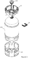
- An exploded view of the keg assembly 1 is illustrated in Figure 2
- the keg 100 is illustrated in isolation in Figures 3a and 3b .
- the keg 100 is a plastic keg that has been stretch blow moulded from a preform of PET.
- the keg 100 has a substantially hemispherical base portion 101 including four blister-like feet 101a arranged in a petaloid formation on which the keg may stand in use.
- the keg 100 is designed to be capable of being operated in a freestanding configuration resting on the feet 101, including during pressurised dispensing, although in the present embodiment the keg 100 is intended to be used in combination with a bottom chime 50.
- the keg 100 further comprises a cylindrical main body portion 102 with a substantially constant cross-section that is integrally formed with and extends upwardly from the top of the base portion 101, and a substantially hemispherical shoulder portion 103 that is integrally formed with the body portion at the top edge thereof.
- the base portion 101, the main body portion 102 and the shoulder portion 103 together define a body of the keg 100.
- the keg 100 is provided with a neck portion 104 that defines an opening of the keg 100.
- the neck portion 104 includes an upper circumferential flange 104a and a lower circumferential flange 104b.
- the neck portion 104 of the keg 100 is configured to receive and retain a closure 105 (illustrated in Figures 1a, 1c and 2 ), which may be secured to the neck portion 104 of the keg 100 by a snap-fit engagement with the upper circumferential flange 104a.
- the closure 105 defines a pair of concentric flow paths into and out of the keg 100 that may be selectively opened and closed by a valve arrangement.
- the closure 105 includes a spear connector for connection to a dip tube or spear that extends to a location near to the bottom of the keg 100 when the closure 105 is mounted to the keg 100.
- the keg 100 is a keg for use in the distribution and pressurised dispensing of draught beer, and is configured to operate at a working pressure of 3 bar (gauge pressure) and to be able to independently withstand an internal pressure of at least 5 bar (gauge pressure).
- the keg 100 has a sidewall thickness of approximately 0.5mm in its main body portion 102, and a capacity of approximately 20 litres.
- the keg 100 comprises upper and lower annular protrusions 106, 107 that extend around the body of the keg 100 and project outwardly from the underlying contour of the keg body towards the upper and lower ends of the main body portion 102.
- the annular protrusions 106, 107 are configured to retain a sleeve or wrap 108 (indicated with dashed lines in Figure 1 c) which may be applied to the body of the keg 100 between the annular protrusions 106, 107.
- the wrap 108 may be a non-structural wrap, may be mounted to the keg 100 independently of the top and bottom chimes, and may be used to display branding and/or information related to the keg 100 or its contents.
- the annular protrusions 106, 107 also define contact portions via which adjacent kegs stored next to each other may contact each other.
- the annular protrusions 106, 107 each have an outside diameter that is substantially identical to the outside diameter of the bottom chime 50 (which is slightly greater than the outside diameter of the underlying contour of the main body portion 102 of the keg 100).
- the annular protrusions 106, 107 therefore substantially eliminate the gaps between adjacent keg bodies at the locations of the annular protrusions when a plurality of keg assemblies 1 are stored directly adjacent to each other, thereby improving the stability of contact between adjacent keg assemblies 1.
- the keg 100 further comprises a set of four retaining recesses 110 that are spaced apart around the circumference of the keg 100 at a transition region between the base portion 101 and the main body portion 102 of the keg 100.
- the retaining recesses 110 each extend inwardly with respect to the underlying contour of the keg 100, and are elongate in a circumferential direction with respect to the keg 100.
- Each retaining recess 110 extends approximately one eighth of the distance around the circumference of the keg 100.
- the retaining recesses 110 are separated from each other by intervening regions 111 of the keg body in which the underlying contour of the keg is not interrupted, the intervening regions 111 each extending approximately one eighth of the distance around the circumference of the keg.
- the cumulative length of the retaining recesses 110 is therefore approximately 50% of the circumference of the keg 100 at the location of the retaining recesses 110.
- the retaining recesses 110 are configured to engage corresponding engagement elements provided on the bottom chime when the bottom chime 50 is mounted to the keg 100, as described in detail below.
- the keg 100 may be supplied to a user such as a beverage manufacturer as a preform.
- the preform may then be stored in its compact form, and may be stretch blow moulded into its final keg shape on site and on demand.
- top and bottom chimes and their interactions with the keg 100 will now be described. It will be appreciated that all references to directions made throughout this specification, such as “top”, “bottom”, “upper”, “lower”, “upwardly”, “downwardly”, “vertical” and “horizontal” are made with respect to a keg assembly 1 in upright orientation as illustrated in Figure 1b . It will further be appreciated that the orientations of each part of the keg assembly 1 may vary in use, for example if the keg assembly 1 is stored or used in an orientation different to that illustrated in Figure 1b .
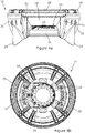
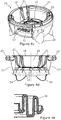
- top chime 10 is illustrated in isolation in Figures 4a to 4e , in which Figure 4a illustrates a side view of the top chime, Figure 4b illustrates a plan view from above the top chime, Figure 4c illustrates a perspective view of the top chime, Figure 4d illustrates a cross-section view through the top chime, and Figure 4e illustrates a cross-section view through a handle of the top chime.
- the top chime 10 comprises a central mounting portion 11 or body portion that is configured for mounting the top chime 10 to the keg 100 in combination with a separate mounting element or collar 30, which is described in detail below.
- the mounting portion 11 is generally annular in shape and defines a central aperture 12 that is configured to receive the neck portion 104 of the keg 100.
- the mounting portion 11 comprises a plurality of resiliently deformable tines 13 that are circumferentially spaced around the mounting portion 11 and extend radially inwardly into the central aperture 12.
- the tines 13 are separated from each other by a series of radially extending slots, and are each generally planar with a substantially rectangular shape in plan-view that terminates at a radially inner distal end.
- the distal ends of the tines 13 define an inner portion of the central aperture 12 with a diameter that is slightly larger than the outside diameter of the neck portion 104 of the keg 100 (excluding the flanges 104a, 104b) such that the inner ends of the tines 13 are slightly spaced apart from the radially outer surface of the neck portion 104 when the top chime 10 has been mounted to the keg 100 and is exactly centred with respect to the keg 100.
- one or more of the tines may engage the radially outer surface of the neck portion 104 if the top chime is slightly misaligned and/or if the keg has expanded under internal pressurisation.
- each tine 13 includes a kinked region or a region of reduced thickness adjacent to its connection with the mounting portion 11 of the top chime 10 that is configured to assist with deflection of the tines 13, although in other embodiments each tine 13 may have a substantially constant thickness without any kinked region.
- the mounting portion 11 has a generally convex shape around its circumference, and is configured to engage the upper shoulder portion 103 of the keg 100 around its outer edge but to be spaced apart from the keg 100 inboard of its outer edge.
- the mounting portion 11 is additionally provided with a plurality of resiliently deformable contact elements or spring blades 14 that are spaced apart around the circumference of the mounting portion 11 and configured to engage the upper shoulder portion 103 of the keg 100.
- the spring blades 14 are each connected to the mounting portion 11 adjacent to the central aperture 12, and each extend downwardly and radially outwardly from the mounting portion 11.
- the spring blades 14 each have a curved shape that bends radially outwardly with respect to the longitudinal axis of the top chime along their length directions away from the mounting portion 11.
- Each spring blade 14 defines a contact surface that is configured to continuously engage the upper shoulder portion 103 of the keg 100 when the top chime 10 has been mounted to the keg 100, the contact surfaces being angled to compliment the contour of the upper shoulder portion 103 of the keg 100.
- the spring blades are configured to transfer forces between the top chime 10 and the keg 100.
- the spring blades may bear at least a portion of the weight of the keg 100 when the keg assembly 1 is placed in an inverted configuration for filling, and may reduce impact forces experienced by the keg 100 when an impact force is imparted to the top chime 10.
- the spring blades 14 also act to assist with correct alignment of the top chime 10 with respect to the keg 100.
- the mounting portion 11 has an upwardly facing top surface 15, illustrated in plan view in Figure 4b , that is configured to be engaged by the collar 30 to thereby secure the top chime 10 with respect to the keg 100 and prevent movement of the top chime 10 in an axially outward direction with respect to the keg 100.
- the upper surface 15 of the mounting portion 11 is provided with a pair of guide formations 16 that are configured to engage side edges of the collar 30 to guide the collar as the collar is moved into its mounted position with respect to the top chime 10.
- the mounting portion 11 is also provided with a resiliently movable latch or lock formation 17 that is configured to engage a rear edge of the collar 30 to prevent outward movement of the collar away from its mounted position after having been mounted to the top chime 10.
- the top chime 10 further comprises an annular crown portion 18 that forms the upper-most and radially outer-most part of the top chime 10.
- the crown portion 18 is configured to extend above the top of the neck portion 104 of the keg 100 and the closure 105 when the top chime 10 has been mounted to the keg 100 in order to provide protection to the neck portion 104 and the closure 105.
- the crown portion 18 has an outside diameter that is smaller than the outside diameter of the bottom chime 50, and is configured to be received within an annular groove provided at the base of the bottom chime to facilitate stacking of keg assemblies 1.
- the crown portion 18 defines a large central recess 19 into which the neck portion 104 of the keg 100 and the closure 105 protrude when the top chime 10 has been mounted to the keg 100, providing access around the closure 105.
- the recess 19 may have a diameter that is at least twice the size of the diameter of the neck portion 104 and/or the closure 105.
- the crown portion 18 is configured to enable the closure 105 to be coupled to a filling head or a dispense head while the top chime 10 is mounted to the keg 100, and provides a stable base for the keg assembly 1 when in an inverted orientation, for example in a conventional steel keg filling line.
- the crown portion 18 comprises a pair of handles 20 located on opposite sides of the crown portion 18 by which the keg assembly 1 may be handled in use, for example by a user or a keg handling machine.
- Each handle 20 has a waveform profile when viewed in cross section along a length direction of the handle (in a plane perpendicular to the length direction of the handle), as illustrated in Figure 4e .
- the waveform profile is defined by a continuous handle element that includes a plurality of regions of inflection or peaks and troughs forming opposing upper and lower surfaces of the handle 20.
- the waveform profile results in handles 20 that are strong and stiff with optimised use of material, and also provides comfortable gripping surfaces to be griped by a user.
- the handles 20 include reinforcing webs that extend between the vertical walls of the continuous handle elements to provide reinforcement to the handles 20, for example at the location of the cross-section view illustrated in Figure 4d .
- the crown portion 18 is connected to the mounting portion 11 of the top chime 10 by a plurality of elongate arms 21 that extend axially upwardly and radially outwardly from the mounting portion 11 with respect to a longitudinal axis of the top chime, and by a pair of outer side walls 22 on opposing sides of the top chime 10 that extend between adjacent arms 21.
- the arms 21 are each formed by a plurality of webs that are arranged in planes that extend in substantially radial directions with respect to the longitudinal axis of the top chime 10.
- the arms 21 and the outer side walls 22 each curve outwardly with respect to the longitudinal axis of the top chime 10 between the mounting portion 11 and the crown portion 18.
- the top chime 10 also includes a pair of side access apertures 23 located on opposing sides of the top chime 10 that extend between adjacent arms 21 beneath the handles 20 and provide access to the interior 19 of the top chime 10 as well as facilitating use of the handles 20.
- the top chime 10 further comprises a set of four rigid, pillar-like feet 24 that extend outwardly and downwardly from the outer side walls 22.
- the feet 24 are configured to engage an outer part of the upper shoulder portion 103 of the keg 100 when the top chime 10 has been mounted to the keg 100, for example to aid the transfer of forces between the keg 100 and the top chime 10, especially when the keg assembly 1 is placed in an inverted orientation such that the keg 100 bears downwardly on the top chime 10.
- the mounting element or collar 30, which is supplied together with the top chime 10 as a separate component, is illustrated in isolation in Figures 5a and 5b .
- the collar 30 is a substantially planar component, and has a generally U-shaped or horseshoe-shaped form in plan view (as illustrated in Figure 5a ).
- the collar 30 is split or open sided and is configured to receive the neck portion 104 of the keg 100 in use.
- the collar 30 has a substantially straight rear outside edge 30a at its closed side, and a pair of substantially straight side edges 30b, 30c that extend away from the rear edge 30a along the sides of the collar 30.
- the collar 30 comprises a pair of arms 32 that extend outwardly from a main body 31 of the collar.
- the inner arms 32 are configured to be resiliently deformed away from each other, and to receive the neck portion 104 of the keg 100 with a snap fit engagement.
- the collar 30 also comprises an outer pair of arms 33 that extend outwardly from the main body 31 adjacent to and radially outboard of the inner arms 32.
- the collar 30 further comprises arcuate inner and outer contact formations 34, 35 that each extend around the collar.
- the inner contact formation 34 extends around the main body 31 and the inner arms 32 adjacent to the inside edge of the collar, and is configured to engage the underside of the lower circumferential flange 104b provided on the neck portion 104 of the keg 100 in use.
- the outer contact formation 35 extends around the main body 31 and the outer arms 33 outboard of the inner contact formation 34, and is configured to engage the upper surface 15 of the mounting portion 11 of the top chime 10 in use.
- the top chime 10 When it is desired to mount the top chime 10 to the keg 100, the top chime 10 is first moved into a mounted position with respect to the keg 100 with the neck portion 104 of the keg 100 protruding through the central aperture 12 in the mounting portion 11 and into the central recess 19 defined within the crown portion 18. This step may be performed after the closure 105 has been fitted to the neck portion 104, preferably before the keg 100 has been pressurised and filled with beverage.
- the tines 13 in the central aperture 12 are deflected upwardly and outwardly with respect to the top chime 10 over the closure 105 and the lower circumferential flange 104b, and then snap underneath the lower flange 104b to prevent accidental dislodgement of the top chime 10 from the keg 100 before the top chime 10 has been secured to the keg 100 using the collar 30.
- the tines 13 also act to ensure that the top chime 10 is correctly centred with respect to the keg 100.
- the collar 30 is then assembled together with the top chime 10 to thereby secure the top chime 10 with respect to the keg 100.
- the collar 30 is passed through one of the access apertures 23 with the open side of the collar facing towards the neck portion 104 of the keg 100.
- the collar 30 is then slid along the upper surface 15 of the mounting portion 11 of the top chime 10 in a direction perpendicular to the longitudinal axis of the top chime 10 and the neck portion 104 of the keg 100 (as indicated by an arrow in Figure 6 ) until the neck portion 104 is received within the collar 30 and the inner arms 32 form a snap fit engagement with the neck portion 104.
- the guide formations 16 provided on the mounting portion 11 of the top chime 10 engage the side edges 30b, 30c of the collar 30 to thereby guide the collar 30 along a defined path with respect to the mounting portion 11.
- the lock formation 17 provided on the mounting portion 11 of the top chime 10 snaps into engagement with the rear edge 30a of the collar 30 to thereby prevent outward movement of the collar 30 away from its mounted position, and the guide formations 16 act to prevent rotation of the collar 30 with respect to the top chime 10.
- the collar 30 When the collar 30 has reached its fully mounted position as illustrated in Figure 6 , the collar 30 becomes sandwiched between underside of the lower circumferential flange 104b on the neck portion 104 of the keg 100 and the upper surface 15 of the mounting portion 11 of the top chime 10, with the inner contact formation 34 of the collar 30 engaging the underside of the lower circumferential flange 104b and the outer contact formation 35 engaging the upper surface 15 of the mounting portion 11. In this way the collar 30 secures the top chime 10 with respect to the keg 100 and prevents axial movement of the top chime 10 away from the keg 100. The collar 30 also acts to transfer the weight of the keg 100 to the top chime 10 when the keg assembly 1 is lifted by the top chime 10.
- the lock formation 17 on the mounting portion 11 of the top chime 10 may be manually depressed in order to release the collar 30 and permit the collar 30 to be moved radially outwardly from its mounted position and out of its engagement with the neck portion 104 of the keg 100.
- the top chime 10 may then be removed from the neck portion 104 of the keg 100 by manually pulling the top chime 10 axially outwardly away from the keg 100.
- the tines 13 provide some resistance to removal of the top chime 10 from the keg 100.
- the tines 13 are configured to allow the top chime to be manually removed from the keg 100 without the application of excessive force and without the use of specific tools.
- the tines 13 may optionally be configured to allow the top chime 10 to be removed from the keg 100 without damaging the top chime 10, the keg 100 or the closure 105.
- the top chime 10 may be configured such that one or more of the tines 13 break or become permanently deformed in order to permit removal of the top chime 10 from the keg 100.
- top chime 10 Once the top chime 10 has been removed from the keg 100 it is then possible to dispose of the keg 100, for example by crushing and recycling the keg, while the top chime 10 and the collar 30 may be recycled separately to the keg as part of a one-way keg system. If the top chime 10 can be removed from the keg without becoming significantly damaged then it may additionally be possible to retain or return the top chime 10 for subsequent use with another keg.
- Figure 8 illustrates a second mounting element or collar insert 81 that may be used together with the collar 30 of figures 5a and 5b .
- the collar insert 81 comprises a pair of arms that extend outwardly from a main body. The arms are configured to be resiliently deformed away from each other, and to receive the neck portion 104 of the keg 100 with a snap fit engagement.
- Figures 9a and 9b illustrate a possible method for mounting the top chime 10 to the keg 100, using both the collar 30 and the collar insert 81.
- the collar insert 81 is passed through one of the access apertures 23 with the open side of the collar insert 81 facing towards the neck portion 104 of the keg 100 ( Figure 9a ).
- the collar insert 81 is then slid along the upper surface 15 of the mounting portion 11 of the top chime 10 in a direction perpendicular to the longitudinal axis of the top chime 10 and the neck portion 104 of the keg 100 until the neck portion 104 is received within the collar insert 81 and the arms form a snap fit engagement with the neck portion 104.
- the collar insert 81 becomes loosely sandwiched between underside of the lower circumferential flange 104b on the neck portion 104 of the keg 100 and the upper surface 15 of the mounting portion 11 of the top chime 10.
- the collar insert 81 When positioned between the circumferential flange 104b and the top chime 10, the collar insert 81 is rotated over an angle of about 180° with respect to the longitudinal axis of the top chime 10. As a result, the open side of the collar insert 81 again faces the access aperture 23, but now from the inside of the chime 10. Also in this position, the collar insert 81 is sandwiched between the circumferential flange 104b of the neck portion 104 and the upper surface 15 of the mounting portion 11 of the top chime 10.
- the collar 30 When the collar insert 81 is in the rotated position, the collar 30 is inserted through the access aperture 23in the same way as described above with reference to Figures 5a, 5b and 6 . Then, the collar 30 is inserted in between the collar insert 81 and the circumferential flange 104b of the neck 104. When also the arms of the collar 30 snap around the neck 104 of the keg 100, the collar 30 and the collar insert 81 together surround the full circumference of the neck 104 and are sandwiched between the circumferential flange 104b and the top chime upper surface 15. The collar 30 may then be axially locked by the lock formation 17 as described before.
- the rotation step can be omitted.
- the bottom chime 50 is illustrated in isolation in Figures 7a to 7d , in which Figure 7a illustrates a side view of the bottom chime, Figure 7b illustrates a cross-section view through the bottom chime, Figure 7c illustrates a plan view from above the bottom chime, and Figure 7d illustrates a perspective view of the bottom chime.
- the bottom chime 50 comprises a generally annular base section 51 that extends across the bottom chime 50 at the lower end thereof.
- the base section 51 includes a downwardly extending lower rim 52 on which the bottom chime 50 is configured to sit in use, and an annular groove located inboard of the lower rim 52 that is configured to receive the crown portion 18 of a top chime 10 in order to facilitate stacking of keg assemblies 1.
- the base section 51 comprises a central aperture 53 formed therethrough.
- the base section 51 further comprises a set of four handle apertures 54 that are spaced apart around the central aperture 43 in proximity to an outside edge of the base section 51 and configured to be gripped by a user, for example to facilitate chest carrying of the keg assembly 1.
- the bottom chime 50 further comprises a substantially annular sleeve or outer wall 55 that extends upwardly from the base section 51.
- the base section 51 and the sleeve 55 together define a socket that is configured to receive and surround the base portion 101 of the keg 100 when the bottom chime 50 has been mounted to the keg 100, as illustrated in Figures 1a to 1d .
- the sleeve 55 includes a lower section 55a that extends continuously around the circumference of the bottom chime 50, and an upper section 55b that includes a set of four through slots 56 that extend downwardly from a top end of the sleeve 55 to divide the upper section 55b of the sleeve into four circumferentially spaced tabs 57.
- the lower section 55a of the sleeve includes a set of four depressions 58 that are spaced apart around the circumference of the bottom chime 50 and each extend inwardly with respect to the overall contour of the sleeve 55.
- the depressions 58 are aligned with the handle apertures 54 and facilitate gripping of the bottom chime 50 through the handle apertures 54.
- Each depression 58 provides a lower lip at its base that may be gripped by a user, for example to assist with removal of the bottom chime 50 from the keg 100 as described below.
- the depressions 58 are separated by outer pillar portions 59 that substantially follow the outer contour of the sleeve 55.
- the slots 56 extending from the upper end of the sleeve 55 are aligned with the outer pillar portions 59.
- the bottom chime 50 comprises a set of four engagement elements 60 that are provided adjacent to the top end of the sleeve 55 on the respective tabs 57 forming the upper section 55b of the sleeve 55.
- Each engagement element 60 extends radially inwardly from its respective tab 57, and is elongate in a circumferential direction with respect to the bottom chime 50, extending substantially across the width of its respective tab 57.
- Each engagement element 60 has a curved, ramped upper surface 60a, and a hooked underside.
- Each tab 57 is provided with an aperture 61 or through hole located axially below its respective engagement element 60.
- the apertures 60 facilitate inclusion of the depressions 58 since the base portion 101 of the keg 100 is able to protrude through the apertures 61 between the depressions 58 and the engagement elements 60, as well as allowing inspection of the bottom part of the keg 100 when the bottom chime 50 has been mounted to the keg 100.
- the bottom chime 50 further comprises a set of four resiliently deformable support elements 62 that are configured to engage the underlying contour of the base portion 101 of the keg 100 between the feet 101a when the bottom chime 50 has been mounted to the keg 100 in order to support the weight of the keg 100.
- Each support element 62 comprises a connecting strut 62a that extends upwardly from the base section 51 of the bottom chime 50, and a support portion 62b that extends radially inwardly from an upper end of the connecting strut 62a.
- the support portions 62b each provide an upwardly facing contact surface for engaging the base portion 101 of the keg 100.
- the contact surfaces are shaped to match the underlying contour of the base portion 101 of the keg 100 between the feet 101a.
- the support elements 62 are connected to the base section 51 adjacent to and radially outboard of the handle apertures 54, and the connecting struts 62a of the support elements 62 each provide an inner surface for a respective one of the handles 54.
- the connecting struts 62a of the support elements 62 are each connected to the outer wall of the sleeve 55 by a plurality or reinforcing webs in order to provide reinforcement to the handles.
- the bottom chime 50 is configured to be push fitted to the bottom end of the keg 100 after the keg 100 has been formed (for example by blow moulding), but preferably before the keg 100 has been pressurised and filled with beverage.
- the bottom chime 50 may be push fitted to the bottom end of the keg 100 by lowering the keg 100 into the bottom chime 50 while the bottom chime 50 is resting on the floor or another appropriate surface.
- the keg 100 is preferably oriented with respect to the bottom chime 50 with the feet 101a aligned with the slots 56, in which state the retaining recesses 110 provided on the body of the keg 100 are aligned with the respective engagement elements 60 of the bottom chime 50.
- the keg 100 may then be lowered into the bottom chime 50.
- the slots 56 may act to guide the feet 101a with respect to the bottom chime 50.
- the tabs 57 on which the engagement elements 60 are provided are deflected radially outwardly in order to allow the keg 100 to proceed into its fully mounted position with respect to the bottom chime 50.
- the bottom chime 50 is configured to remain securely mounted to the keg 100 as long as the keg 100 remains pressurised. However, after the keg 100 has been depressurised following the dispensing of beverage the keg becomes less stiff, and the bottom chime 50 may then be manually removed from the keg 100 without requiring the use of any specific tools and without damaging the bottom chime 50 by pulling the bottom chime 50 in an axially outward direction with respect to the keg 100. It is then possible to dispose of the keg 100, for example by crushing and recycling the keg, while the bottom chime 50 may be recycled separately to the keg as part of a one-way keg system. If the bottom chime 50 can be removed from the keg without becoming significantly damaged then it may additionally be possible to retain or return the bottom chime 50 for subsequent use with another keg.
- the top chime 10, the collar 30 and the bottom chime 50 may each be injection moulded plastic components, and may each be formed of, for example high density polyethylene, polypropylene or nylon, although other materials are also possible.
- the collar is configured to be passed through an access aperture formed in a side face of the top chime and moved in a direction perpendicular to the longitudinal axis of the top chime until it reaches a fully mounted position in which it surrounds the neck portion of the keg.
- the collar may instead be configured to be assembled together with the top chime by first passing the collar downwardly through the opening formed at the top of the crown portion before moving the collar radially inwardly into engagement with the neck portion of the keg.
- the mounting element need not surround the neck portion of the keg, and the collar described above may instead be replaced by a plurality of separate mounting elements that each engage the underside of the lower circumferential flange of the neck portion at respective locations spaced apart around the mounting portion of the top chime.
- the keg has four feet and the bottom chime includes sets of four slots, tabs, engagement elements, depressions and handles.
- the keg may have a different number of feet or no feet, and the bottom chime may include a different number of slots, tabs, engagement elements, depressions and handles.
- keg assembly including both a top chime and a bottom chime
- the keg assembly may include a keg and a top chime only.
Landscapes
- Engineering & Computer Science (AREA)
- Mechanical Engineering (AREA)
- Ceramic Engineering (AREA)
- Details Of Rigid Or Semi-Rigid Containers (AREA)
- Packages (AREA)
- Closures For Containers (AREA)
Claims (15)
- Kopfring (10), der konfiguriert ist, um an einem Keg-Fass (100) befestigt zu werden; wobei der Kopfring (10) einen Befestigungsabschnitt (11) zum Befestigen des Kopfrings (10) an dem Keg-Fass (100) in Verwendung umfasst, wobei der Befestigungsabschnitt (11) eine Öffnung (12) definiert, die konfiguriert ist, um einen Halsabschnitt (104) des Keg-Fasses (100) aufzunehmen; wobei der Kopfring (10) konfiguriert ist, um von dem Fass (100) durch Ziehen des Kopfrings (10) in eine axial nach außen weisende Richtung hinsichtlich des Keg-Fasses (100) entfernbar zu sein, nachdem er an dem Keg-Fass (100) befestigt wurde, wobei der Kopfring (10) mit einem Befestigungselement (30) versehen ist, das konfiguriert ist, um den Befestigungsabschnitt (11) in Eingriff zu nehmen, um dadurch den Kopfring (10) hinsichtlich des Keg-Fasses (100) zu sichern und dadurch gekennzeichnet, dass das Befestigungselement (30) konfiguriert ist, um zusammen mit dem Kopfring (10) durch Bewegen des Befestigungselements (30) in eine radial nach innen weisende Richtung hinsichtlich einer Längsachse des Kopfrings (10) montiert zu werden.
- Kopfring (10) nach Anspruch 1, wobei das Befestigungselement (30) konfiguriert ist, um zusammen mit dem Kopfring (10) durch Bewegen des Befestigungselements (30) in eine Richtung, die wenigstens im Wesentlichen senkrecht zu der Längsachse des Kopfrings (10) ist, montiert zu werden.
- Kopfring (10) nach Anspruch 1 oder 2, wobei das Befestigungselement (30) konfiguriert ist, um zusammen mit dem Kopfring (10) durch Schieben des Befestigungselements (30) in eine befestigte Position hinsichtlich des Kopfrings (10) montiert zu werden.
- Kopfring (10) nach einem der Ansprüche 1 bis 3, wobei der Kopfring (10) eine Zugangsöffnung (23) umfasst, die in einer Seitenfläche davon bereitgestellt ist, wobei das Befestigungselement (30) konfiguriert ist, um durch die Zugangsöffnung (23) zu laufen, um zusammen mit dem Kopfring (10) montiert zu werden.
- Kopfring (10) nach einem der Ansprüche 1 bis 4, wobei das Befestigungselement (30) konfiguriert ist, um zusammen mit dem Kopfring (10) montiert zu werden, nachdem der Kopfring (10) in eine befestigte Position hinsichtlich des Keg-Fasses (100) bewegt wurde.
- Kopfring (10) nach einem der Ansprüche 1 bis 5, wobei das Befestigungselement (30) konfiguriert ist, um eine Auflageoberfläche des Befestigungsabschnitts (11) in Eingriff zu nehmen, um dadurch den Kopfring (10) hinsichtlich des Keg-Fasses (100) in Verwendung zu sichern.
- Kopfring (10) nach einem der Ansprüche 1 bis 6, wobei das Befestigungselement (11) einen Kragen (30) umfasst, der konfiguriert ist, um den Halsabschnitt (104) des Keg-Fasses (100) wenigstens teilweise zu umgeben.
- Kopfring (10) nach Anspruch 7, wobei das Befestigungselement (11) konfiguriert ist, um den Halsabschnitt (104) des Keg-Fasses (100) mit einem Schnappeingriff aufzunehmen.
- Kopfring (10) nach Anspruch 7 oder 8, wobei das Befestigungselement (30) wenigstens ein elastisches Element (32) umfasst, das konfiguriert ist, um einer Entfernung des Befestigungselements (30) von dem Halsabschnitt (104) des Keg-Fasses (100) in eine radiale Richtung hinsichtlich einer Längsachse des Keg-Fasses (100) standzuhalten, wenn das Befestigungselement (30) mit dem Halsabschnitt (104) des Keg-Fasses (100) gekoppelt wurde.
- Kopfring (10) nach einem der Ansprüche 1 bis 9, wobei der Kopfring (10) eine Verriegelungsanordnung (17) umfasst, die konfiguriert ist, um das Befestigungselement (30) in einer befestigten Position hinsichtlich des Kopfrings (10) festzuhalten.
- Kopfring (10) nach einem der vorhergehenden Ansprüche, wobei der Befestigungsabschnitt (11) des Kopfrings (10) mehrere Zinken (13) umfasst, die sich in die Öffnung (12) radial nach innen weisend erstrecken.
- Kopfring (10) nach einem der vorhergehenden Ansprüche, wobei der Kopfring (10) mehrere Kontaktelemente (14) umfasst, die konfiguriert sind, um einen oberen Schulterabschnitt (103) des Keg-Fasses (100) in Verwendung in Eingriff zu nehmen.
- Kopfring (10) nach Anspruch 12, wobei die Kontaktelemente (14) mehrere Füße einschließen, die um eine Außenkante des Kopfrings (10) herum beabstandet sind.
- Kopfring (10) nach einem der vorhergehenden Ansprüche, der ferner mit einem zweiten Befestigungselement (81) versehen ist, wobei das zweite Befestigungselement (81) konfiguriert ist, um zusammen mit dem Kopfring (10) durch Bewegen des zweiten Befestigungselements (81) in eine radial nach innen weisende Richtung hinsichtlich einer Längsachse des Kopfrings (10) so montiert zu werden, dass das Befestigungselement (30) und das zweite Befestigungselement (81) zusammen einen Kragen ausbilden, der den Halsabschnitt (104) des Keg-Fasses (100) umgibt.
- Kopfring (10) nach Anspruch 14, wobei der Befestigungsabschnitt (11) des Kopfrings (10) mehrere Zinken (13) umfasst, die sich in die Öffnung (12) radial nach innen weisend erstrecken, wobei das Befestigungselement (30) und das zweite Befestigungselement (81) konfiguriert sind, um so befestigt zu werden, dass sie zusammen zwischen den Zinken (13) und einem Umfangsflansch (104b) an dem Halsabschnitt (104) des Keg-Fasses (100) eingeschlossen sind.
Priority Applications (1)
| Application Number | Priority Date | Filing Date | Title |
|---|---|---|---|
| PL18709724T PL3585694T3 (pl) | 2017-02-27 | 2018-02-27 | Górne obrzeże dla kegu na napoje |
Applications Claiming Priority (3)
| Application Number | Priority Date | Filing Date | Title |
|---|---|---|---|
| GB1703148.5A GB2560024B (en) | 2017-02-27 | 2017-02-27 | Keg chime |
| GB1705593.0A GB2560051B (en) | 2017-02-27 | 2017-04-06 | Top chime for a beverage keg |
| PCT/GB2018/050499 WO2018154334A1 (en) | 2017-02-27 | 2018-02-27 | Top chime for a beverage keg |
Publications (2)
| Publication Number | Publication Date |
|---|---|
| EP3585694A1 EP3585694A1 (de) | 2020-01-01 |
| EP3585694B1 true EP3585694B1 (de) | 2021-08-11 |
Family
ID=58544382
Family Applications (3)
| Application Number | Title | Priority Date | Filing Date |
|---|---|---|---|
| EP18715063.6A Active EP3585696B1 (de) | 2017-02-27 | 2018-02-27 | Fassklimme |
| EP18709724.1A Active EP3585694B1 (de) | 2017-02-27 | 2018-02-27 | Kopfring für ein getränkefass |
| EP18715062.8A Active EP3585695B1 (de) | 2017-02-27 | 2018-02-27 | Fussring und getränkefass |
Family Applications Before (1)
| Application Number | Title | Priority Date | Filing Date |
|---|---|---|---|
| EP18715063.6A Active EP3585696B1 (de) | 2017-02-27 | 2018-02-27 | Fassklimme |
Family Applications After (1)
| Application Number | Title | Priority Date | Filing Date |
|---|---|---|---|
| EP18715062.8A Active EP3585695B1 (de) | 2017-02-27 | 2018-02-27 | Fussring und getränkefass |
Country Status (11)
| Country | Link |
|---|---|
| US (3) | US11420787B2 (de) |
| EP (3) | EP3585696B1 (de) |
| JP (1) | JP7093360B2 (de) |
| CN (1) | CN110382366B (de) |
| BR (1) | BR112019015995A2 (de) |
| CA (1) | CA3051650C (de) |
| ES (2) | ES2897670T3 (de) |
| GB (3) | GB2560024B (de) |
| MX (1) | MX2019009593A (de) |
| PL (2) | PL3585695T3 (de) |
| WO (3) | WO2018154334A1 (de) |
Families Citing this family (14)
| Publication number | Priority date | Publication date | Assignee | Title |
|---|---|---|---|---|
| GB2560024B (en) | 2017-02-27 | 2020-04-22 | Petainer Large Container Ip Ltd | Keg chime |
| US11470855B2 (en) * | 2018-08-17 | 2022-10-18 | Coldsnap, Corp. | Providing single servings of cooled foods and drinks |
| US10543978B1 (en) | 2018-08-17 | 2020-01-28 | Sigma Phase, Corp. | Rapidly cooling food and drinks |
| US20220017266A1 (en) * | 2019-04-22 | 2022-01-20 | Valerie Chandra Hetzel | Hand-footholds for buckets, troughs, tubs, containers, redeptacles, and bins |
| USD935327S1 (en) * | 2019-08-09 | 2021-11-09 | Gpcp Ip Holdings Llc | Wiper bucket system |
| USD930109S1 (en) * | 2020-08-06 | 2021-09-07 | Amtrol Licensing, Inc. | Handle |
| USD995972S1 (en) * | 2021-01-13 | 2023-08-15 | Siya, Inc. | Bucket holder |
| US11801973B2 (en) | 2021-07-01 | 2023-10-31 | William Stacy | Forkliftable steel drum |
| ES3012543T3 (en) * | 2022-05-27 | 2025-04-09 | Alps Electric Ireland Ltd | Connector for connecting an electronic device, especially an electronic tracking device, to a container, electronic assembly for a container, and container assembly |
| DE102022119050A1 (de) * | 2022-07-29 | 2024-02-01 | AS Strömungstechnik Gesellschaft mit beschränkter Haftung | Entnahmesystem |
| USD1124227S1 (en) * | 2023-02-17 | 2026-04-28 | Amtrol Licensing Inc. | Handle |
| US12031364B2 (en) * | 2023-09-19 | 2024-07-09 | Wenfeng Peng | Child lock structure, hook structure, handle structure and heating barrel |
| CN118992281A (zh) * | 2024-09-04 | 2024-11-22 | 南京乐惠芬纳赫包装机械有限公司 | 一种pet啤酒桶以及桶的把手和底座的安装方式 |
| KR102902568B1 (ko) * | 2024-11-07 | 2025-12-23 | (주)빌리언에코산업 | 직립용 굽을 구비한 포장용기 |
Family Cites Families (54)
| Publication number | Priority date | Publication date | Assignee | Title |
|---|---|---|---|---|
| US2049977A (en) * | 1932-11-28 | 1936-08-04 | Du Pont | Container |
| US2087349A (en) * | 1934-06-16 | 1937-07-20 | Hubert H Lucker | Beer keg |
| US2341740A (en) * | 1940-07-11 | 1944-02-15 | Triplex Barrel Company Inc | Barrel or keg |
| US2481015A (en) * | 1945-08-01 | 1949-09-06 | Borg Warner | Chime construction for steel barrels |
| GB1127305A (en) * | 1966-01-05 | 1968-09-18 | Grundy Teddington Ltd | Improvements in casks and like containers |
| GB1374977A (en) * | 1970-12-02 | 1974-11-20 | Fairey Stainless Ltd | Double-walled containers and their manufacture |
| US3889839A (en) * | 1974-05-30 | 1975-06-17 | Advanced Chem Tech | Blow-molded drum |
| US4294374A (en) * | 1975-11-28 | 1981-10-13 | Owens-Illinois, Inc. | Plastic drum assembly |
| FR2357437A1 (fr) * | 1976-07-07 | 1978-02-03 | Carnaud Total Interplastic | Corps creux en matiere plastique soumis a une pression interne |
| FI57239C (fi) * | 1977-06-10 | 1980-07-10 | Hackman Ab Oy | Flyttbar distributionsbehaollare foer vaetskor pulver el dyl |
| US4915913A (en) * | 1984-05-22 | 1990-04-10 | Genesis Medical Corporation | Medical sterilizer device with improved latch mechanism |
| DE3437622A1 (de) * | 1984-10-13 | 1986-04-24 | Pfaudler-Werke Ag, 6830 Schwetzingen | Doppelmantel fuer einen emaillierten behaelter |
| US4593818A (en) * | 1985-04-29 | 1986-06-10 | Schenkman Roger B | Can stacker |
| DE8528229U1 (de) * | 1985-10-03 | 1985-11-21 | Hof, Michael, 5920 Berleburg | Transportables Faß |
| DE3708432A1 (de) * | 1987-03-16 | 1988-09-29 | Mauser Werke Gmbh | Spundfass |
| US4735338A (en) | 1987-06-29 | 1988-04-05 | Stancil Danny R | Removable fastener for pot lid |
| US6047846A (en) * | 1991-02-25 | 2000-04-11 | Greif Bros. Corp. Of Ohio | Plastic drum with drain sump |
| JPH06345096A (ja) * | 1993-06-04 | 1994-12-20 | Mitsubishi Plastics Ind Ltd | 脚台付きポリエステルボトル |
| DE9320107U1 (de) | 1993-12-29 | 1994-03-03 | Sotralentz S.A., Drulingen | Durch Blasformgebung aus thermoplastischem Kunststoff geformtes Faß |
| US5385259A (en) | 1994-01-28 | 1995-01-31 | Safety 1St, Inc. | Diaper pail |
| JPH101141A (ja) * | 1996-06-18 | 1998-01-06 | Inchikeepu Maaketeingu Japan Kk | ビール樽の手掛け部構造 |
| JP3859792B2 (ja) * | 1997-01-31 | 2006-12-20 | 竹内工業株式会社 | 化粧品用容器 |
| US5735428A (en) | 1997-04-10 | 1998-04-07 | Chern; Yuh Shun | Sealing container |
| DE19723114A1 (de) * | 1997-06-03 | 1998-12-10 | Schaefer Werke Gmbh | Behälter, insbesondere Edelstahl- oder Kunststoffaß |
| DE29816750U1 (de) * | 1998-09-18 | 1998-12-17 | Schäfer Werke GmbH, 57290 Neunkirchen | Behälter |
| JP2001010673A (ja) * | 1999-06-29 | 2001-01-16 | Shiseido Co Ltd | 衝撃吸収容器 |
| DE10052378A1 (de) * | 2000-10-20 | 2002-04-25 | Messer Griesheim Gmbh | Sicheres Entnehmen von flüssigem Ammoniak aus Gasflaschen zu Reduzierung von NOx im Abgasstrom von Verbrennungsmaschinen |
| US6789692B2 (en) | 2001-07-13 | 2004-09-14 | Louis M. Prezelin | Container latch valve |
| JP4716303B2 (ja) * | 2001-07-27 | 2011-07-06 | 株式会社吉野工業所 | 衝撃吸収容器 |
| DE20115158U1 (de) * | 2001-09-14 | 2002-02-14 | Schäfer Werke GmbH, 57290 Neunkirchen | Getränke-Ausschankeinrichtung |
| US20060186136A1 (en) * | 2002-11-29 | 2006-08-24 | Albert Wauters | Beer dispensing apparatus |
| GB0411292D0 (en) * | 2004-05-20 | 2004-06-23 | Interbrew Sa | Chime for an alcohol containing cask |
| WO2005113344A1 (en) * | 2004-05-20 | 2005-12-01 | Topchoice Investments Pty Ltd | Vessel with handling formation and detachable base portion |
| GB0411291D0 (en) * | 2004-05-20 | 2004-06-23 | Interbrew Sa | Alcohol containing cask and chime assembly |
| GB2446392A (en) | 2007-02-12 | 2008-08-13 | Inbev Sa | A Plastic Upper Chime and Keg Assembly for Beverage Kegs |
| RU2470843C2 (ru) * | 2007-02-12 | 2012-12-27 | Инбев С.А. | Контейнер и утор и способ изготовления упомянутого контейнера |
| RU2494936C2 (ru) * | 2007-02-12 | 2013-10-10 | Инбев С.А. | Контейнер, утор и их сборка |
| GB2446393A (en) * | 2007-02-12 | 2008-08-13 | Inbev Sa | A Plastic Lower Chime and Keg Assembly for Beverage Kegs |
| KR100830370B1 (ko) | 2008-02-29 | 2008-05-20 | 석종철 | 밀폐용기의 뚜껑 |
| GB2452599B (en) * | 2008-08-20 | 2011-04-20 | Global Polymer Solutions Ltd | Pressure vessel |
| US9475607B2 (en) * | 2008-10-01 | 2016-10-25 | Rehrig Pacific Company | Plastic beer keg |
| DE102008057632B4 (de) * | 2008-11-10 | 2015-01-22 | Huber Packaging Group Gmbh | Tragevorrichtung |
| US9434505B2 (en) * | 2010-01-26 | 2016-09-06 | Rehrig Pacific Company | Plastic beer keg |
| BE1019342A5 (nl) * | 2010-05-20 | 2012-06-05 | Dispack Projects Nv | Vat uit kunststof, werkwijze voor het vervaardigen daarvan, en ring voor een vat. |
| GB2481436A (en) * | 2010-06-24 | 2011-12-28 | Silvia Romana Marabini | Chime attachment means and tamper evident cap |
| GB2481439B (en) | 2010-06-25 | 2015-07-08 | Asg Group Ltd | Connection arrangement |
| GB2490966B (en) | 2011-05-20 | 2013-12-11 | Petainer Lidkoping Ab | Keg support system |
| BRPI1102874B1 (pt) | 2011-06-22 | 2021-12-07 | Somma Technology Engenharia Ltda | Conjunto de anéis de alça e de base substituíveis para um reservatório pressurizado e reservatório pressurizado |
| JP5404739B2 (ja) * | 2011-10-27 | 2014-02-05 | コダマ樹脂工業株式会社 | 樹脂製容器 |
| DE102014113915A1 (de) * | 2014-09-25 | 2016-03-31 | Krones Aktiengesellschaft | Komprimierbares Kunststoffbehältnis mit Bodentasse |
| US20180022594A1 (en) * | 2014-10-31 | 2018-01-25 | First Element Packaging Inc. | Container for receiving and storing fluid |
| GB2532223B (en) * | 2014-11-11 | 2017-11-15 | Petainer Large Container Ip Ltd | Keg protection assembly |
| GB2541758B (en) * | 2015-12-07 | 2018-01-10 | Plastic Keg Co Ltd | Containers |
| GB2560024B (en) | 2017-02-27 | 2020-04-22 | Petainer Large Container Ip Ltd | Keg chime |
-
2017
- 2017-02-27 GB GB1703148.5A patent/GB2560024B/en not_active Expired - Fee Related
- 2017-04-06 GB GB1705593.0A patent/GB2560051B/en active Active
- 2017-04-06 GB GB1705592.2A patent/GB2560050B/en active Active
-
2018
- 2018-02-27 US US16/488,009 patent/US11420787B2/en active Active
- 2018-02-27 WO PCT/GB2018/050499 patent/WO2018154334A1/en not_active Ceased
- 2018-02-27 EP EP18715063.6A patent/EP3585696B1/de active Active
- 2018-02-27 EP EP18709724.1A patent/EP3585694B1/de active Active
- 2018-02-27 JP JP2019546023A patent/JP7093360B2/ja active Active
- 2018-02-27 US US16/487,014 patent/US11230409B2/en active Active
- 2018-02-27 CA CA3051650A patent/CA3051650C/en active Active
- 2018-02-27 WO PCT/GB2018/050501 patent/WO2018154336A1/en not_active Ceased
- 2018-02-27 PL PL18715062T patent/PL3585695T3/pl unknown
- 2018-02-27 ES ES18709724T patent/ES2897670T3/es active Active
- 2018-02-27 ES ES18715062T patent/ES2897693T3/es active Active
- 2018-02-27 BR BR112019015995-9A patent/BR112019015995A2/pt not_active IP Right Cessation
- 2018-02-27 MX MX2019009593A patent/MX2019009593A/es unknown
- 2018-02-27 EP EP18715062.8A patent/EP3585695B1/de active Active
- 2018-02-27 PL PL18709724T patent/PL3585694T3/pl unknown
- 2018-02-27 WO PCT/GB2018/050498 patent/WO2018154333A1/en not_active Ceased
- 2018-02-27 CN CN201880014409.5A patent/CN110382366B/zh active Active
- 2018-02-27 US US16/487,012 patent/US11027879B2/en not_active Expired - Fee Related
Also Published As
Similar Documents
| Publication | Publication Date | Title |
|---|---|---|
| CA3051650C (en) | Top chime for a beverage keg | |
| US8348086B2 (en) | Plastic beer keg | |
| EP2640646B1 (de) | Stapelbarer behälter mit kopfring | |
| US5657871A (en) | Container with a stacking ring | |
| US9845178B2 (en) | Compressible plastic container with base cup | |
| US20180222657A1 (en) | Keg protection assembly | |
| WO2012160036A1 (en) | Keg support system | |
| US10189695B2 (en) | Keg cover | |
| IT201600112071A1 (it) | Corpo valvola, corpo contenitore e contenitore per fluidi in pressione, particolarmente per bevande. |
Legal Events
| Date | Code | Title | Description |
|---|---|---|---|
| STAA | Information on the status of an ep patent application or granted ep patent |
Free format text: STATUS: UNKNOWN |
|
| STAA | Information on the status of an ep patent application or granted ep patent |
Free format text: STATUS: THE INTERNATIONAL PUBLICATION HAS BEEN MADE |
|
| PUAI | Public reference made under article 153(3) epc to a published international application that has entered the european phase |
Free format text: ORIGINAL CODE: 0009012 |
|
| STAA | Information on the status of an ep patent application or granted ep patent |
Free format text: STATUS: REQUEST FOR EXAMINATION WAS MADE |
|
| 17P | Request for examination filed |
Effective date: 20190923 |
|
| AK | Designated contracting states |
Kind code of ref document: A1 Designated state(s): AL AT BE BG CH CY CZ DE DK EE ES FI FR GB GR HR HU IE IS IT LI LT LU LV MC MK MT NL NO PL PT RO RS SE SI SK SM TR |
|
| AX | Request for extension of the european patent |
Extension state: BA ME |
|
| DAV | Request for validation of the european patent (deleted) | ||
| DAX | Request for extension of the european patent (deleted) | ||
| GRAP | Despatch of communication of intention to grant a patent |
Free format text: ORIGINAL CODE: EPIDOSNIGR1 |
|
| STAA | Information on the status of an ep patent application or granted ep patent |
Free format text: STATUS: GRANT OF PATENT IS INTENDED |
|
| INTG | Intention to grant announced |
Effective date: 20201015 |
|
| RAP1 | Party data changed (applicant data changed or rights of an application transferred) |
Owner name: PETAINER LARGE CONTAINER IP LIMITED |
|
| GRAJ | Information related to disapproval of communication of intention to grant by the applicant or resumption of examination proceedings by the epo deleted |
Free format text: ORIGINAL CODE: EPIDOSDIGR1 |
|
| STAA | Information on the status of an ep patent application or granted ep patent |
Free format text: STATUS: REQUEST FOR EXAMINATION WAS MADE |
|
| GRAP | Despatch of communication of intention to grant a patent |
Free format text: ORIGINAL CODE: EPIDOSNIGR1 |
|
| STAA | Information on the status of an ep patent application or granted ep patent |
Free format text: STATUS: GRANT OF PATENT IS INTENDED |
|
| INTC | Intention to grant announced (deleted) | ||
| INTG | Intention to grant announced |
Effective date: 20210312 |
|
| GRAS | Grant fee paid |
Free format text: ORIGINAL CODE: EPIDOSNIGR3 |
|
| GRAA | (expected) grant |
Free format text: ORIGINAL CODE: 0009210 |
|
| STAA | Information on the status of an ep patent application or granted ep patent |
Free format text: STATUS: THE PATENT HAS BEEN GRANTED |
|
| AK | Designated contracting states |
Kind code of ref document: B1 Designated state(s): AL AT BE BG CH CY CZ DE DK EE ES FI FR GB GR HR HU IE IS IT LI LT LU LV MC MK MT NL NO PL PT RO RS SE SI SK SM TR |
|
| REG | Reference to a national code |
Ref country code: CH Ref legal event code: EP |
|
| REG | Reference to a national code |
Ref country code: DE Ref legal event code: R096 Ref document number: 602018021619 Country of ref document: DE |
|
| REG | Reference to a national code |
Ref country code: IE Ref legal event code: FG4D Ref country code: AT Ref legal event code: REF Ref document number: 1419178 Country of ref document: AT Kind code of ref document: T Effective date: 20210915 |
|
| REG | Reference to a national code |
Ref country code: NL Ref legal event code: FP |
|
| REG | Reference to a national code |
Ref country code: LT Ref legal event code: MG9D |
|
| REG | Reference to a national code |
Ref country code: AT Ref legal event code: MK05 Ref document number: 1419178 Country of ref document: AT Kind code of ref document: T Effective date: 20210811 |
|
| PG25 | Lapsed in a contracting state [announced via postgrant information from national office to epo] |
Ref country code: PT Free format text: LAPSE BECAUSE OF FAILURE TO SUBMIT A TRANSLATION OF THE DESCRIPTION OR TO PAY THE FEE WITHIN THE PRESCRIBED TIME-LIMIT Effective date: 20211213 Ref country code: NO Free format text: LAPSE BECAUSE OF FAILURE TO SUBMIT A TRANSLATION OF THE DESCRIPTION OR TO PAY THE FEE WITHIN THE PRESCRIBED TIME-LIMIT Effective date: 20211111 Ref country code: BG Free format text: LAPSE BECAUSE OF FAILURE TO SUBMIT A TRANSLATION OF THE DESCRIPTION OR TO PAY THE FEE WITHIN THE PRESCRIBED TIME-LIMIT Effective date: 20211111 Ref country code: AT Free format text: LAPSE BECAUSE OF FAILURE TO SUBMIT A TRANSLATION OF THE DESCRIPTION OR TO PAY THE FEE WITHIN THE PRESCRIBED TIME-LIMIT Effective date: 20210811 Ref country code: LT Free format text: LAPSE BECAUSE OF FAILURE TO SUBMIT A TRANSLATION OF THE DESCRIPTION OR TO PAY THE FEE WITHIN THE PRESCRIBED TIME-LIMIT Effective date: 20210811 Ref country code: RS Free format text: LAPSE BECAUSE OF FAILURE TO SUBMIT A TRANSLATION OF THE DESCRIPTION OR TO PAY THE FEE WITHIN THE PRESCRIBED TIME-LIMIT Effective date: 20210811 Ref country code: SE Free format text: LAPSE BECAUSE OF FAILURE TO SUBMIT A TRANSLATION OF THE DESCRIPTION OR TO PAY THE FEE WITHIN THE PRESCRIBED TIME-LIMIT Effective date: 20210811 Ref country code: FI Free format text: LAPSE BECAUSE OF FAILURE TO SUBMIT A TRANSLATION OF THE DESCRIPTION OR TO PAY THE FEE WITHIN THE PRESCRIBED TIME-LIMIT Effective date: 20210811 Ref country code: HR Free format text: LAPSE BECAUSE OF FAILURE TO SUBMIT A TRANSLATION OF THE DESCRIPTION OR TO PAY THE FEE WITHIN THE PRESCRIBED TIME-LIMIT Effective date: 20210811 |
|
| PG25 | Lapsed in a contracting state [announced via postgrant information from national office to epo] |
Ref country code: LV Free format text: LAPSE BECAUSE OF FAILURE TO SUBMIT A TRANSLATION OF THE DESCRIPTION OR TO PAY THE FEE WITHIN THE PRESCRIBED TIME-LIMIT Effective date: 20210811 Ref country code: GR Free format text: LAPSE BECAUSE OF FAILURE TO SUBMIT A TRANSLATION OF THE DESCRIPTION OR TO PAY THE FEE WITHIN THE PRESCRIBED TIME-LIMIT Effective date: 20211112 |
|
| REG | Reference to a national code |
Ref country code: ES Ref legal event code: FG2A Ref document number: 2897670 Country of ref document: ES Kind code of ref document: T3 Effective date: 20220302 |
|
| PG25 | Lapsed in a contracting state [announced via postgrant information from national office to epo] |
Ref country code: DK Free format text: LAPSE BECAUSE OF FAILURE TO SUBMIT A TRANSLATION OF THE DESCRIPTION OR TO PAY THE FEE WITHIN THE PRESCRIBED TIME-LIMIT Effective date: 20210811 |
|
| REG | Reference to a national code |
Ref country code: DE Ref legal event code: R097 Ref document number: 602018021619 Country of ref document: DE |
|
| PG25 | Lapsed in a contracting state [announced via postgrant information from national office to epo] |
Ref country code: SM Free format text: LAPSE BECAUSE OF FAILURE TO SUBMIT A TRANSLATION OF THE DESCRIPTION OR TO PAY THE FEE WITHIN THE PRESCRIBED TIME-LIMIT Effective date: 20210811 Ref country code: SK Free format text: LAPSE BECAUSE OF FAILURE TO SUBMIT A TRANSLATION OF THE DESCRIPTION OR TO PAY THE FEE WITHIN THE PRESCRIBED TIME-LIMIT Effective date: 20210811 Ref country code: RO Free format text: LAPSE BECAUSE OF FAILURE TO SUBMIT A TRANSLATION OF THE DESCRIPTION OR TO PAY THE FEE WITHIN THE PRESCRIBED TIME-LIMIT Effective date: 20210811 Ref country code: EE Free format text: LAPSE BECAUSE OF FAILURE TO SUBMIT A TRANSLATION OF THE DESCRIPTION OR TO PAY THE FEE WITHIN THE PRESCRIBED TIME-LIMIT Effective date: 20210811 Ref country code: AL Free format text: LAPSE BECAUSE OF FAILURE TO SUBMIT A TRANSLATION OF THE DESCRIPTION OR TO PAY THE FEE WITHIN THE PRESCRIBED TIME-LIMIT Effective date: 20210811 |
|
| PLBE | No opposition filed within time limit |
Free format text: ORIGINAL CODE: 0009261 |
|
| STAA | Information on the status of an ep patent application or granted ep patent |
Free format text: STATUS: NO OPPOSITION FILED WITHIN TIME LIMIT |
|
| 26N | No opposition filed |
Effective date: 20220512 |
|
| PG25 | Lapsed in a contracting state [announced via postgrant information from national office to epo] |
Ref country code: SI Free format text: LAPSE BECAUSE OF FAILURE TO SUBMIT A TRANSLATION OF THE DESCRIPTION OR TO PAY THE FEE WITHIN THE PRESCRIBED TIME-LIMIT Effective date: 20210811 |
|
| PG25 | Lapsed in a contracting state [announced via postgrant information from national office to epo] |
Ref country code: MC Free format text: LAPSE BECAUSE OF FAILURE TO SUBMIT A TRANSLATION OF THE DESCRIPTION OR TO PAY THE FEE WITHIN THE PRESCRIBED TIME-LIMIT Effective date: 20210811 |
|
| REG | Reference to a national code |
Ref country code: CH Ref legal event code: PL |
|
| PG25 | Lapsed in a contracting state [announced via postgrant information from national office to epo] |
Ref country code: LU Free format text: LAPSE BECAUSE OF NON-PAYMENT OF DUE FEES Effective date: 20220227 |
|
| PG25 | Lapsed in a contracting state [announced via postgrant information from national office to epo] |
Ref country code: FR Free format text: LAPSE BECAUSE OF NON-PAYMENT OF DUE FEES Effective date: 20220228 |
|
| PG25 | Lapsed in a contracting state [announced via postgrant information from national office to epo] |
Ref country code: LI Free format text: LAPSE BECAUSE OF NON-PAYMENT OF DUE FEES Effective date: 20220228 Ref country code: IE Free format text: LAPSE BECAUSE OF NON-PAYMENT OF DUE FEES Effective date: 20220227 Ref country code: CH Free format text: LAPSE BECAUSE OF NON-PAYMENT OF DUE FEES Effective date: 20220228 |
|
| PG25 | Lapsed in a contracting state [announced via postgrant information from national office to epo] |
Ref country code: MK Free format text: LAPSE BECAUSE OF FAILURE TO SUBMIT A TRANSLATION OF THE DESCRIPTION OR TO PAY THE FEE WITHIN THE PRESCRIBED TIME-LIMIT Effective date: 20210811 Ref country code: CY Free format text: LAPSE BECAUSE OF FAILURE TO SUBMIT A TRANSLATION OF THE DESCRIPTION OR TO PAY THE FEE WITHIN THE PRESCRIBED TIME-LIMIT Effective date: 20210811 |
|
| PG25 | Lapsed in a contracting state [announced via postgrant information from national office to epo] |
Ref country code: HU Free format text: LAPSE BECAUSE OF FAILURE TO SUBMIT A TRANSLATION OF THE DESCRIPTION OR TO PAY THE FEE WITHIN THE PRESCRIBED TIME-LIMIT; INVALID AB INITIO Effective date: 20180227 |
|
| PG25 | Lapsed in a contracting state [announced via postgrant information from national office to epo] |
Ref country code: MT Free format text: LAPSE BECAUSE OF FAILURE TO SUBMIT A TRANSLATION OF THE DESCRIPTION OR TO PAY THE FEE WITHIN THE PRESCRIBED TIME-LIMIT Effective date: 20210811 |
|
| PG25 | Lapsed in a contracting state [announced via postgrant information from national office to epo] |
Ref country code: TR Free format text: LAPSE BECAUSE OF FAILURE TO SUBMIT A TRANSLATION OF THE DESCRIPTION OR TO PAY THE FEE WITHIN THE PRESCRIBED TIME-LIMIT Effective date: 20210811 |
|
| PGFP | Annual fee paid to national office [announced via postgrant information from national office to epo] |
Ref country code: NL Payment date: 20260220 Year of fee payment: 9 |
|
| PGFP | Annual fee paid to national office [announced via postgrant information from national office to epo] |
Ref country code: GB Payment date: 20260226 Year of fee payment: 9 |
|
| PGFP | Annual fee paid to national office [announced via postgrant information from national office to epo] |
Ref country code: ES Payment date: 20260317 Year of fee payment: 9 |
|
| PGFP | Annual fee paid to national office [announced via postgrant information from national office to epo] |
Ref country code: DE Payment date: 20260220 Year of fee payment: 9 |
|
| PGFP | Annual fee paid to national office [announced via postgrant information from national office to epo] |
Ref country code: BE Payment date: 20260220 Year of fee payment: 9 Ref country code: IT Payment date: 20260219 Year of fee payment: 9 |
|
| PGFP | Annual fee paid to national office [announced via postgrant information from national office to epo] |
Ref country code: CZ Payment date: 20260212 Year of fee payment: 9 |
|
| PGFP | Annual fee paid to national office [announced via postgrant information from national office to epo] |
Ref country code: PL Payment date: 20260204 Year of fee payment: 9 |