EP3585649B1 - Retroviseur exterieur de vehicule automobile supportant une garniture de porte - Google Patents
Retroviseur exterieur de vehicule automobile supportant une garniture de porte Download PDFInfo
- Publication number
- EP3585649B1 EP3585649B1 EP18710087.0A EP18710087A EP3585649B1 EP 3585649 B1 EP3585649 B1 EP 3585649B1 EP 18710087 A EP18710087 A EP 18710087A EP 3585649 B1 EP3585649 B1 EP 3585649B1
- Authority
- EP
- European Patent Office
- Prior art keywords
- door
- base
- lining
- glass frame
- bottom portion
- Prior art date
- Legal status (The legal status is an assumption and is not a legal conclusion. Google has not performed a legal analysis and makes no representation as to the accuracy of the status listed.)
- Active
Links
Images

Classifications
-
- B—PERFORMING OPERATIONS; TRANSPORTING
- B60—VEHICLES IN GENERAL
- B60J—WINDOWS, WINDSCREENS, NON-FIXED ROOFS, DOORS, OR SIMILAR DEVICES FOR VEHICLES; REMOVABLE EXTERNAL PROTECTIVE COVERINGS SPECIALLY ADAPTED FOR VEHICLES
- B60J5/00—Doors
- B60J5/04—Doors arranged at the vehicle sides
- B60J5/0401—Upper door structure
- B60J5/0404—Outside rear view mirror support
-
- B—PERFORMING OPERATIONS; TRANSPORTING
- B60—VEHICLES IN GENERAL
- B60R—VEHICLES, VEHICLE FITTINGS, OR VEHICLE PARTS, NOT OTHERWISE PROVIDED FOR
- B60R1/00—Optical viewing arrangements; Real-time viewing arrangements for drivers or passengers using optical image capturing systems, e.g. cameras or video systems specially adapted for use in or on vehicles
- B60R1/02—Rear-view mirror arrangements
- B60R1/06—Rear-view mirror arrangements mounted on vehicle exterior
Definitions
- the invention relates to the field of motor vehicles, more particularly to the front doors of a motor vehicle.
- the front doors of a motor vehicle are generally pivotally attached to a front pillar. They include a metal structure including a window frame extending upward from a box, but also a mirror and a door trim, commonly called slide, fixed to the window frame using a sheet metal part. additional, and used to seal the door.
- the mirror generally located at the rear of the trim, is fixed to the metal structure.
- the published patent document FR 2 975 352 shows the preamble of claim 1 and discloses a device for positioning an exterior mirror for a motor vehicle.
- the rear-view mirror comprises a base positioned on a support of the door, said support being surmounted by a seal or slide.
- the device comprises tabs located on the base and fitting into notches formed in the lining. The engagement of the tabs in the notches requires a certain care, and therefore a certain time, during the assembly operations.
- this type of attachment requires the base to remain set back relative to the contour of the trim, which may prove to be limiting in terms of the style of the vehicle.
- the object of the invention is to overcome at least one of the drawbacks of the above-mentioned state of the art. More particularly, the object of the invention is to facilitate the fitting of the trim on the door without however presenting constraints at the level of the shape of the base which can prove to be penalizing at the level of the style of the vehicle.
- the subject of the invention is a front door for a motor vehicle, comprising: a metal structure with a box and a window frame extending upwards from the box, said frame comprising a front and lower portion; an exterior mirror with a base fixed to the front and lower portion of the window frame; a trim extending along an upper face of the window frame to the portion front and bottom of said frame; remarkable in that the base extends forwards beyond the front and lower portion of the window frame and is fixed to the trim at the front of said portion.
- the gasket is a gasket with the vehicle body. It is commonly referred to as “backstage”.
- the trim comprises first means for fixing to the front and lower portion of the window frame and second means for fixing to the base.
- the first and / or second fixing means are of the pin type inserted into an orifice.
- the first and second fixing means are positioned on a front end of the lining.
- the trim comprises third means for fixing to a joining rebate of sheets situated at the front of the front and lower portion of the window frame.
- the third fixing means form a notch fitting the junction rabbet.
- the first fixing means are located at the rear of the second and third fixing means, and cooperate with a face of the front and lower portion of the window frame which is directed inwardly. of the vehicle.
- the lining comprises a rigid support forming the notch and a tab supporting the second fixing means.
- the rigid support is advantageously made of metal.
- the subject of the invention is also a motor vehicle comprising at least one front door, remarkable in that the front door is in accordance with the invention, and a section of the trim fixed to the base of the mirror and hidden by said base of such that a front edge of said base forms a finishing connecting edge with an adjacent front wing.
- the distance between the finishing connecting edge and the front fender is between 2 and 10 mm, and more preferably the distance is between 3 and 7mm.
- the subject of the invention is also a method for assembling a front door of a motor vehicle, remarkable in that the door is according to the invention and the method comprises the following steps: mounting the trim on the upper face of the frame door and fixing said trim to an inner face of the front and lower portion of the window frame; mounting and fixing of the mirror on the front and lower portion of the window frame; fixing of the trim to the base of the mirror.
- the measures of the invention are advantageous in that they facilitate the mounting of the gasket on the door while allowing the base to extend in front of the gasket.
- the addition of a rigid support between the base and the trim improves the rigidity and therefore the holding of the mirror.
- Fixing the front end of the trim against an inner face of the mirror base also has the function of improving the aerodynamics of the vehicle, by promoting the design of a new design of the side doors of the vehicle.
- the invention also makes it possible to reduce the assembly time of the lining on the door.
- the door 5 comprises a metal structure forming a box 7 in its lower part and a window frame 11 extending upwardly from said box 7.
- This window frame supports the trim 23, said trim 23 forming a profile.
- the door 5 further comprises an exterior mirror 13 positioned at the front and at the bottom of the window frame 11.
- the mirror 13 includes an outer shell 17 at the rear of which is inserted a mirror 19.
- Said shell 17 may also comprise a flashing light 21 making it possible to indicate a change of direction of the vehicle 1 to the users.
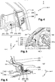
- the mirror 13 is fixed to the door 5 by means of a base 15 comprising a finishing connection portion 15A extending above, in the transverse direction y, of the trim 23 to the front fender 3 and a gusset 15B positioned above the connection portion 15A, these two elements being joined on the inside by a support of the base 15C (visible in figure 2 ).
- the figure 2 is a view of the support 15C of the base 15 of the mirror 13 of the figure 1 .
- the support 15C is used for fixing the mirror 13 on the door 5 and for fixing the the trim 23 on the base 15 of the mirror 13.
- This support 15C comprises in particular a connector for the electric cable 15C.2 serving among other things to control the positioning of the mirror 19, and 15C.1 fixing holes which will accommodate means for fixing the base 15, for example of the screw type.
- the figures 3 and 4 show respectively front and rear views of the gasket 23 such as figure 1 .
- the profile of the trim 23 comprises a front end 27 positioned behind the base 15 following the transverse direction y. This end 27 can be subdivided into an anterior portion 27A positioned at the level of an anterior portion of the base 15 and a posterior portion 27B extending longitudinally towards the rear from the anterior portion 27A.
- These portions (27A, 27B) comprise fixing means (27C, 27D, 27E), preferably arranged in fixing holes provided in the lining 23.
- the first fixing means (27C, 27E) allow the fixing of the lining 23 to the window frame of the door 5 while the second fixing means 27D allow the fixing of the gasket 23 to the base 15.
- a rigid support 29, forming third fixing means, can be added in order to improve the rigidity of the lining 23.
- This rigid support 29 is then fixed behind, in the transverse direction y, said lining 23 and positioned between the lining 23 and the support of the base 15.
- This rigid support 29 comprises a notch 29A and a tab 29B , which will be better described in the figure 6 .
- the figure 5 shows the fixing of the trim 23 on the support 15C of the base 15 of the mirror 13.
- This fixing is carried out according to the following steps.
- the trim 23 is mounted on the upper face of the door frame 5, then the first fixing means (27C, 27E) is fixed by the trim 23 to an inner face of a front and lower portion of the window frame (shown in figure 6 ).
- the mounting and fixing of the mirror 13 is carried out on the front and lower portion of the window frame.
- the fixing of the trim 23 to the base 15 of the mirror 13 is achieved by means of the second fixing means 27D.
- the end 27 of the lining 23 is then positioned on the support 15C, at the level of the connection portion 15A of the base 15 for the anterior portion 27A, and longitudinally towards the rear of the support 15C for the posterior portion 27B.
- the figure 6 is a section of the door 5 with the gasket 23 according to the invention.
- the door 5 comprises a front and lower portion of the window frame 9 positioned behind the base 15, in the transverse direction y, and terminating at the front in a joining rebate of sheets 31.
- the trim 23 is shown attached to the door. the front and lower portion 9 of the window frame by a pin 27C of the first fixing means.
- the rigid support 29 fixes the lining 23 to the support 15C of the underlying base 15 by means of the second fixing means 27D.
- Said rigid support 29 comprises the tab 29B positioned between the lining 23 and the support 15C, then extended outwards by the notch 29A.
- This notch 29A has a U-shaped section fitting the sheet junction rebate 31.
Landscapes
- Engineering & Computer Science (AREA)
- Mechanical Engineering (AREA)
- Multimedia (AREA)
- Rear-View Mirror Devices That Are Mounted On The Exterior Of The Vehicle (AREA)
Description
- L'invention a trait au domaine des véhicules automobiles, plus particulièrement aux portes avant d'un véhicule automobile.
- Les portes avant d'un véhicule automobile sont généralement fixées de manière pivotante à un pilier avant. Elles comprennent une structure métallique incluant un cadre de vitre s'étendant vers le haut depuis un caisson, mais aussi un rétroviseur et une garniture de porte, couramment appelée coulisse, fixée sur le cadre de vitre à l'aide d'une pièce en tôle supplémentaire, et servant à étanchéifier la porte. Le rétroviseur, généralement situé à l'arrière de la garniture, est fixé sur la structure métallique.
- Le document de brevet publié
FR 2 975 352 - L'invention a pour objectif de pallier au moins un des inconvénients de l'état de la technique susmentionné. Plus particulièrement, l'invention a pour objectif de faciliter le montage de la garniture sur la porte sans pour autant présenter des contraintes au niveau de la forme de l'embase qui peuvent s'avérer pénalisantes au niveau du style du véhicule.
- L'invention a pour objet une porte avant de véhicule automobile, comprenant : une structure métallique avec un caisson et un cadre de vitre s'étendant vers le haut depuis le caisson, ledit cadre comprenant une portion avant et inférieure ; un rétroviseur extérieur avec une embase fixée à la portion avant et inférieure du cadre de vitre ; une garniture s'étendant le long d'une face supérieure du cadre de vitre jusqu'à la portion avant et inférieure dudit cadre ; remarquable en ce que l'embase s'étend vers l'avant au-delà de la portion avant et inférieure du cadre de vitre et est fixée à la garniture à l'avant de ladite portion.
- La garniture est une garniture d'étanchéité avec la caisse du véhicule. Elle est couramment désignée « coulisse ».
- Selon un mode avantageux de l'invention, la garniture comprend des premiers moyens de fixation à la portion avant et inférieure du cadre de vitre et des deuxièmes moyens de fixation à l'embase.
- Selon un mode avantageux de l'invention, les premiers et/ou deuxièmes moyens de fixation sont du type pion à insertion dans un orifice.
- Préférentiellement, les premiers et deuxièmes moyens de fixation sont positionnés sur une extrémité avant de la garniture.
- Selon un mode avantageux de l'invention, la garniture comprend des troisièmes moyens de fixation à une feuillure de jonction de tôles située à l'avant de la portion avant et inférieure du cadre de vitre.
- Selon un mode avantageux de l'invention, les troisièmes moyens de fixation forment une encoche chaussant la feuillure de jonction.
- Selon un mode avantageux de l'invention, les premiers moyens de fixation sont situés à l'arrière des deuxièmes et troisièmes moyens de fixation, et coopèrent avec une face de la portion avant et inférieure du cadre de vitre qui est dirigée vers l'intérieur du véhicule.
- Selon un mode avantageux de l'invention, la garniture comprend un support rigide formant l'encoche et une patte supportant les deuxièmes moyens de fixation. Le support rigide est avantageusement en métal.
- L'invention a également pour objet un véhicule automobile comprenant au moins une porte avant, remarquable en ce que la porte avant est conforme à l'invention, et un tronçon de la garniture fixée à l'embase du rétroviseur et caché par ladite embase de sorte qu'un bord avant de ladite embase forme un bord de raccordement de finition avec une aile avant adjacente.
- Préférentiellement, la distance entre le bord de raccordement de finition et l'aile avant est comprise entre 2 et 10 mm, et plus préférentiellement la distance est entre 3 et 7mm.
- L'invention a également pour objet un procédé d'assemblage d'une porte avant de véhicule automobile, remarquable en ce que la porte est selon l'invention et le procédé comprend les étapes suivantes : montage de la garniture sur la face supérieure du cadre de porte et fixation de ladite garniture à une face intérieure de la portion avant et inférieure du cadre de vitre ; montage et fixation du rétroviseur sur la portion avant et inférieure du cadre de vitre ; fixation de la garniture à l'embase du rétroviseur. Les mesures de l'invention sont intéressantes en ce qu'elles facilitent le montage de la garniture sur la porte tout en permettant à l'embase de s'étendre devant la garniture. L'ajout d'un support rigide entre l'embase et la garniture permet d'améliorer la rigidité donc la tenue du rétroviseur. La fixation de l'extrémité avant de la garniture contre une face intérieure de l'embase du rétroviseur à également pour fonction d'améliorer l'aérodynamisme du véhicule, en favorisant la conception d'un nouveau design des portes latérales du véhicule. L'invention permet également de diminuer le temps de montage de la garniture sur la porte.
- D'autres caractéristiques et avantages de la présente invention seront mieux compris à l'aide de la description et des dessins parmi lesquels :
- La
figure 1 est une vue latérale de la partie avant d'une porte d'un véhicule automobile comprenant une garniture selon l'invention ; - La
figure 2 est une vue de l'embase d'un rétroviseur de lafigure 1 ; - La
figure 3 montre l'extrémité avant de la garniture de lafigure 1 , vue de côté ; - La
figure 4 est une vue arrière de l'extrémité avant de la garniture de lafigure 1 ; - La
figure 5 montre la garniture fixée sur l'embase du rétroviseur de lafigure 1 ; - La
figure 6 est une vue en coupe horizontale de la porte de lafigure 1 , au niveau du rétroviseur. - La
figure 1 est une vue latérale de la partie avant d'une porte avant 5 d'un véhicule automobile 1, ladite porte 5 comprenant une garniture 23 selon l'invention est prolongée par une aile avant 3. On définit alors en référence au véhicule : - une direction longitudinale (axe x) correspondant à la direction de déplacement du véhicule,
- une direction transversale (axe y), perpendiculaire à la direction du déplacement du véhicule, et horizontale,
- une direction verticale (axe z) perpendiculaire au plan (xy).
- La porte 5 comprend une structure métallique formant un caisson 7 dans sa partie basse et un cadre de vitre 11 s'étendant vers le haut à partir dudit caisson 7. Ce cadre de vitre supporte la garniture 23, ladite garniture 23 formant un profilé. La porte 5 comprend en outre un rétroviseur extérieur 13 positionné à l'avant et en bas du cadre de vitre 11. Le rétroviseur 13 inclut une coque externe 17 à l'arrière de laquelle est inséré un miroir 19. Ladite coque 17 peut également comprendre un clignotant 21 permettant d'indiquer un changement de direction du véhicule 1 aux usagers. Le rétroviseur 13 est fixé sur la porte 5 par le biais d'une embase 15 comprenant une portion de raccordement de finition 15A s'étendant au-dessus, suivant la direction transversale y, de la garniture 23 jusqu'à l'aile avant 3 et un gousset 15B positionné au-dessus de la portion de raccordement 15A, ces deux éléments étant joints du côté intérieur par un support de l'embase 15C (visible en
figure 2 ). - La
figure 2 est une vue du support 15C de l'embase 15 du rétroviseur 13 de lafigure 1 . Le support 15C sert à la fixation du rétroviseur 13 sur la porte 5 et à la fixation de la garniture 23 sur l'embase 15 du rétroviseur 13. Ce support 15C comprend notamment un raccord pour le câble électrique 15C.2 servant entre autres à commander le positionnement du miroir 19, et des orifices de fixation 15C.1 qui vont accueillir des moyens de fixation de l'embase 15, par exemple du type vis. - Les
figures 3 et4 montrent respectivement des vues de face et de l'arrière de la garniture 23 telle qu'à lafigure 1 . Le profilé de la garniture 23 comprend une extrémité avant 27 positionnée derrière l'embase 15suivant la direction transversale y. Cette extrémité 27 peut être subdivisée en une portion antérieure 27A positionnée au niveau d'une portion antérieure de l'embase 15 et une portion postérieure 27B s'étendant longitudinalement vers l'arrière depuis la portion antérieure 27A. Ces portions (27A, 27B) comprennent des moyens de fixation (27C, 27D, 27E), préférentiellement disposés dans des orifices de fixation prévus dans la garniture 23. Les premiers moyens de fixation (27C, 27E) permettent la fixation de la garniture 23 au cadre de vitre de la porte 5 tandis que les deuxièmes moyens de fixation 27D permettent la fixation de la garniture 23 à l'embase 15. Un support rigide 29, formant des troisièmes moyens de fixation, peut être ajouté afin d'améliorer la rigidité de la garniture 23. Ce support rigide 29 est alors fixé derrière, suivant la direction transversale y, ladite garniture 23 et positionné entre la garniture 23 et le support de l'embase 15. Ce support rigide 29 comprend une encoche 29A et une patte 29B, qui seront mieux décrites dans lafigure 6 . - La
figure 5 montre la fixation de la garniture 23 sur le support 15C de l'embase 15 du rétroviseur 13. Cette fixation se fait selon les étapes suivantes. On monte la garniture 23 sur la face supérieure du cadre de porte 5, puis on fixe par les premiers moyens de fixation (27C, 27E) la garniture 23 à une face intérieure d'une portion avant et inférieure du cadre de vitre (montrée enfigure 6 ). Ensuite on réalise le montage et la fixation du rétroviseur 13 sur la portion avant et inférieure du cadre de vitre. Enfin, la fixation de la garniture 23 à l'embase 15 du rétroviseur 13 est réalisée grâce aux deuxièmes moyens de fixation 27D. L'extrémité 27 de la garniture 23 est alors positionnée sur le support 15C, au niveau de la portion de raccordement 15A de l'embase 15 pour la portion antérieure 27A, et longitudinalement vers l'arrière du support 15C pour la portion postérieure 27B. - La
figure 6 est une section de la porte 5 avec la garniture 23 selon l'invention. La porte 5 comprend une portion avant et inférieure du cadre de vitre 9 positionnée derrière l'embase 15, suivant la direction transversale y, et se terminant à l'avant par une feuillure de jonction de tôles 31. La garniture 23 est représentée fixée sur la portion avant et inférieure 9 du cadre de la vitre par un pion 27C des premiers moyens de fixation. Le support rigide 29 fixe la garniture 23 au support 15C de l'embase 15 sousjacent par le biais des deuxièmes moyens de fixation 27D. Ledit support rigide 29 comprend la patte 29B positionnée entre la garniture 23 et le support 15C, puis prolongée vers l'extérieur par l'encoche 29A. Cette encoche 29A a une section en forme de U chaussant la feuillure de jonction de tôles 31.
Claims (9)
- Porte avant (5) de véhicule automobile (1), comprenant :- une structure métallique avec un caisson (7) et un cadre de vitre s'étendant vers le haut depuis le caisson (7), ledit cadre comprenant une portion avant et inférieure (9) ;- un rétroviseur extérieur (13) avec une embase (15) fixée à la portion avant et inférieure (9) du cadre de vitre ;- une garniture (23) s'étendant le long d'une face supérieure du cadre de vitre jusqu'à la portion avant et inférieure (9) dudit cadre ;caractérisée en ce que
l'embase (15) s'étend vers l'avant au-delà de la portion avant et inférieure (9) du cadre de vitre et est fixée à la garniture (23) à l'avant de ladite portion (9). - Porte (5) selon la revendication 1, caractérisée en ce que la garniture (23) comprend des premiers moyens de fixation (27C, 27E) à la portion avant et inférieure (9) du cadre de vitre et des deuxièmes moyens de fixation (27D) à l'embase (15).
- Porte (5) selon la revendication 2, caractérisée en ce que les premiers et/ou deuxièmes moyens de fixation (27C, 27D, 27E) sont du type pion à insertion.
- Porte (5) selon l'une des revendications 2 et 3, caractérisée en ce que la garniture (23) comprend des troisièmes moyens de fixation (29A) à une feuillure de jonction de tôles (31) située à l'avant de la portion avant et inférieure (9) du cadre de vitre.
- Porte (5) selon la revendication 4, caractérisée en ce que les troisièmes moyens de fixation (29A) forment une encoche (29A) chaussant la feuillure de jonction (31).
- Porte (5) selon l'une des revendications 2 et 3 et selon l'une des revendications 4 et 5, caractérisée en ce que les premiers moyens de fixation (27C, 27E) sont situés à l'arrière des deuxièmes et troisièmes moyens de fixation (27D, 29A), et coopèrent avec une face de la portion avant et inférieure (9) du cadre de vitre qui est dirigée vers l'intérieur du véhicule (1).
- Porte (5) selon les revendications 5 et 6, caractérisée en ce que la garniture (23) comprend un support rigide (29) formant l'encoche (29A) et une patte (29B) supportant les deuxièmes moyens de fixation (27D).
- Véhicule automobile (1) comprenant au moins une porte avant (5), caractérisé en ce que la porte avant (5) est conforme à l'une des revendications 1 et 7, et un tronçon de la garniture (23) fixée à l'embase (15) du rétroviseur (13) et caché par ladite embase (15) de sorte qu'un bord avant de ladite embase (15) forme un bord de raccordement de finition avec une aile avant (3) adjacente.
- Procédé d'assemblage d'une porte avant (5) de véhicule automobile (1), caractérisé en ce que la porte (5) est selon l'une des revendications 1 à 7 et le procédé comprend les étapes suivantes :- montage de la garniture (23) sur la face supérieure du cadre de porte (5) et fixation de ladite garniture (23) à une face intérieure de la portion avant et inférieure (9) du cadre de vitre ;- montage et fixation du rétroviseur (13) sur la portion avant et inférieure (9) du cadre de vitre ;- fixation de la garniture (23) à l'embase (15) du rétroviseur (13).
Applications Claiming Priority (2)
| Application Number | Priority Date | Filing Date | Title |
|---|---|---|---|
| FR1751498A FR3063251B1 (fr) | 2017-02-24 | 2017-02-24 | Retroviseur exterieur de vehicule automobile supportant une garniture de porte |
| PCT/FR2018/050087 WO2018154198A1 (fr) | 2017-02-24 | 2018-01-15 | Retroviseur exterieur de vehicule automobile supportant une garniture de porte |
Publications (2)
| Publication Number | Publication Date |
|---|---|
| EP3585649A1 EP3585649A1 (fr) | 2020-01-01 |
| EP3585649B1 true EP3585649B1 (fr) | 2021-07-28 |
Family
ID=58993003
Family Applications (1)
| Application Number | Title | Priority Date | Filing Date |
|---|---|---|---|
| EP18710087.0A Active EP3585649B1 (fr) | 2017-02-24 | 2018-01-15 | Retroviseur exterieur de vehicule automobile supportant une garniture de porte |
Country Status (4)
| Country | Link |
|---|---|
| EP (1) | EP3585649B1 (fr) |
| CN (1) | CN110337385B (fr) |
| FR (1) | FR3063251B1 (fr) |
| WO (1) | WO2018154198A1 (fr) |
Families Citing this family (1)
| Publication number | Priority date | Publication date | Assignee | Title |
|---|---|---|---|---|
| CN114619960B (zh) * | 2021-03-29 | 2024-11-29 | 长城汽车股份有限公司 | 汽车 |
Family Cites Families (4)
| Publication number | Priority date | Publication date | Assignee | Title |
|---|---|---|---|---|
| DE2037555C3 (de) * | 1970-07-29 | 1984-02-23 | Bayerische Motoren Werke AG, 8000 München | Ausbildung und Anordnung eines Rückblickspiegels für Seitentüren von Kraftfahrzeugen |
| JPS59220429A (ja) * | 1983-05-30 | 1984-12-11 | Ichikoh Ind Ltd | ドアミラ−の取付部構造 |
| FR2975352B1 (fr) * | 2011-05-16 | 2014-04-25 | Peugeot Citroen Automobiles Sa | Dispositif de positionnement relatif d'un module de retroviseur et d'un support. |
| DE102012023269A1 (de) * | 2012-11-29 | 2014-06-05 | GM Global Technology Operations LLC (n. d. Ges. d. Staates Delaware) | Außenspiegelanordnung für ein Kraftfahrzeug |
-
2017
- 2017-02-24 FR FR1751498A patent/FR3063251B1/fr not_active Expired - Fee Related
-
2018
- 2018-01-15 EP EP18710087.0A patent/EP3585649B1/fr active Active
- 2018-01-15 WO PCT/FR2018/050087 patent/WO2018154198A1/fr not_active Ceased
- 2018-01-15 CN CN201880014088.9A patent/CN110337385B/zh not_active Expired - Fee Related
Non-Patent Citations (1)
| Title |
|---|
| None * |
Also Published As
| Publication number | Publication date |
|---|---|
| WO2018154198A1 (fr) | 2018-08-30 |
| CN110337385A (zh) | 2019-10-15 |
| FR3063251A1 (fr) | 2018-08-31 |
| FR3063251B1 (fr) | 2019-04-05 |
| CN110337385B (zh) | 2023-01-10 |
| EP3585649A1 (fr) | 2020-01-01 |
Similar Documents
| Publication | Publication Date | Title |
|---|---|---|
| EP2209676B1 (fr) | Embout d'extremite pour balai d'essuie-glace | |
| EP0720935B1 (fr) | Dispositif pour le positionnement précis d'un pare-chocs sur une aile d'un véhicule | |
| EP3681746B1 (fr) | Profilé lécheur de vitre avec montage facilité | |
| FR2619766A1 (fr) | Porte de vehicule automobile | |
| EP2678194B1 (fr) | Support d'enrouleur de ceinture de securite | |
| EP3585649B1 (fr) | Retroviseur exterieur de vehicule automobile supportant une garniture de porte | |
| EP3426522B1 (fr) | Embase de retroviseur extérieur de véhicule automobile avec crochet de fixation provisoire | |
| EP1101691B1 (fr) | Fixation quart avant sur traverse | |
| EP2167349A2 (fr) | Agencement de fixation d'une garniture d'une surface de carrosserie automobile au voisinage d'un vitrage | |
| EP3849884B1 (fr) | Bouclier de pare-chocs facilitant le montage d'un deflecteur d'air sur un vehicule automobile | |
| FR3106805A1 (fr) | Agencement de zone arrière de structure de caisse de véhicule dotée d’éléments de renfort latéraux | |
| FR3148954A1 (fr) | Traverse de véhicule automobile permettant un montage longitudinal d’une armature de pare-chocs | |
| EP3283354B1 (fr) | Structure de face avant technique de véhicule automobile en matière plastique | |
| FR3162038A1 (fr) | Agencement de zone arrière de structure de caisse de véhicule automobile à largeur réduite | |
| EP3815980B1 (fr) | Agrafe de retenue d'un bandeau de garniture de porte d'un véhicule automobile | |
| FR3090556A1 (fr) | Renfort arrière supérieur de custode | |
| EP4454954A1 (fr) | Agencement de carrosserie d'un véhicule automobile comportant un obturateur latéral | |
| FR3073193A1 (fr) | Fixation de carrosserie de vehicule automobile a une pointe d’aile arriere | |
| FR3104537A1 (fr) | Interface de fixation monobloc entre une pluralité d'éléments de carrosserie et un pied de porte avant que comporte une caisse de véhicule automobile. | |
| FR3160378A1 (fr) | ensemble de plancher pour véhicule automobile | |
| EP2045171B1 (fr) | Module avant de véhicule automobile et procédé de montage associé | |
| FR3148984A1 (fr) | Déflecteur aéraulique pour véhicule automobile | |
| FR3160377A1 (fr) | Aile de carrosserie d’un véhicule automobile | |
| EP4545363A1 (fr) | Presseur de pare-chocs de véhicule automobile comprenant une extension latérale de renforcement | |
| FR3134359A1 (fr) | Patte de fixation d’un projecteur de véhicule automobile |
Legal Events
| Date | Code | Title | Description |
|---|---|---|---|
| STAA | Information on the status of an ep patent application or granted ep patent |
Free format text: STATUS: UNKNOWN |
|
| STAA | Information on the status of an ep patent application or granted ep patent |
Free format text: STATUS: THE INTERNATIONAL PUBLICATION HAS BEEN MADE |
|
| PUAI | Public reference made under article 153(3) epc to a published international application that has entered the european phase |
Free format text: ORIGINAL CODE: 0009012 |
|
| STAA | Information on the status of an ep patent application or granted ep patent |
Free format text: STATUS: REQUEST FOR EXAMINATION WAS MADE |
|
| 17P | Request for examination filed |
Effective date: 20190705 |
|
| AK | Designated contracting states |
Kind code of ref document: A1 Designated state(s): AL AT BE BG CH CY CZ DE DK EE ES FI FR GB GR HR HU IE IS IT LI LT LU LV MC MK MT NL NO PL PT RO RS SE SI SK SM TR |
|
| AX | Request for extension of the european patent |
Extension state: BA ME |
|
| DAV | Request for validation of the european patent (deleted) | ||
| DAX | Request for extension of the european patent (deleted) | ||
| STAA | Information on the status of an ep patent application or granted ep patent |
Free format text: STATUS: EXAMINATION IS IN PROGRESS |
|
| 17Q | First examination report despatched |
Effective date: 20200828 |
|
| RAP1 | Party data changed (applicant data changed or rights of an application transferred) |
Owner name: PSA AUTOMOBILES SA |
|
| GRAP | Despatch of communication of intention to grant a patent |
Free format text: ORIGINAL CODE: EPIDOSNIGR1 |
|
| STAA | Information on the status of an ep patent application or granted ep patent |
Free format text: STATUS: GRANT OF PATENT IS INTENDED |
|
| INTG | Intention to grant announced |
Effective date: 20210312 |
|
| GRAS | Grant fee paid |
Free format text: ORIGINAL CODE: EPIDOSNIGR3 |
|
| GRAA | (expected) grant |
Free format text: ORIGINAL CODE: 0009210 |
|
| STAA | Information on the status of an ep patent application or granted ep patent |
Free format text: STATUS: THE PATENT HAS BEEN GRANTED |
|
| AK | Designated contracting states |
Kind code of ref document: B1 Designated state(s): AL AT BE BG CH CY CZ DE DK EE ES FI FR GB GR HR HU IE IS IT LI LT LU LV MC MK MT NL NO PL PT RO RS SE SI SK SM TR |
|
| REG | Reference to a national code |
Ref country code: GB Ref legal event code: FG4D Free format text: NOT ENGLISH |
|
| REG | Reference to a national code |
Ref country code: CH Ref legal event code: EP |
|
| REG | Reference to a national code |
Ref country code: DE Ref legal event code: R084 Ref document number: 602018020781 Country of ref document: DE |
|
| REG | Reference to a national code |
Ref country code: AT Ref legal event code: REF Ref document number: 1414463 Country of ref document: AT Kind code of ref document: T Effective date: 20210815 |
|
| REG | Reference to a national code |
Ref country code: IE Ref legal event code: FG4D Free format text: LANGUAGE OF EP DOCUMENT: FRENCH |
|
| REG | Reference to a national code |
Ref country code: DE Ref legal event code: R096 Ref document number: 602018020781 Country of ref document: DE |
|
| REG | Reference to a national code |
Ref country code: GB Ref legal event code: 746 Effective date: 20210910 |
|
| REG | Reference to a national code |
Ref country code: LT Ref legal event code: MG9D |
|
| REG | Reference to a national code |
Ref country code: NL Ref legal event code: MP Effective date: 20210728 |
|
| REG | Reference to a national code |
Ref country code: AT Ref legal event code: MK05 Ref document number: 1414463 Country of ref document: AT Kind code of ref document: T Effective date: 20210728 |
|
| PG25 | Lapsed in a contracting state [announced via postgrant information from national office to epo] |
Ref country code: HR Free format text: LAPSE BECAUSE OF FAILURE TO SUBMIT A TRANSLATION OF THE DESCRIPTION OR TO PAY THE FEE WITHIN THE PRESCRIBED TIME-LIMIT Effective date: 20210728 Ref country code: ES Free format text: LAPSE BECAUSE OF FAILURE TO SUBMIT A TRANSLATION OF THE DESCRIPTION OR TO PAY THE FEE WITHIN THE PRESCRIBED TIME-LIMIT Effective date: 20210728 Ref country code: FI Free format text: LAPSE BECAUSE OF FAILURE TO SUBMIT A TRANSLATION OF THE DESCRIPTION OR TO PAY THE FEE WITHIN THE PRESCRIBED TIME-LIMIT Effective date: 20210728 Ref country code: SE Free format text: LAPSE BECAUSE OF FAILURE TO SUBMIT A TRANSLATION OF THE DESCRIPTION OR TO PAY THE FEE WITHIN THE PRESCRIBED TIME-LIMIT Effective date: 20210728 Ref country code: RS Free format text: LAPSE BECAUSE OF FAILURE TO SUBMIT A TRANSLATION OF THE DESCRIPTION OR TO PAY THE FEE WITHIN THE PRESCRIBED TIME-LIMIT Effective date: 20210728 Ref country code: LT Free format text: LAPSE BECAUSE OF FAILURE TO SUBMIT A TRANSLATION OF THE DESCRIPTION OR TO PAY THE FEE WITHIN THE PRESCRIBED TIME-LIMIT Effective date: 20210728 Ref country code: BG Free format text: LAPSE BECAUSE OF FAILURE TO SUBMIT A TRANSLATION OF THE DESCRIPTION OR TO PAY THE FEE WITHIN THE PRESCRIBED TIME-LIMIT Effective date: 20211028 Ref country code: AT Free format text: LAPSE BECAUSE OF FAILURE TO SUBMIT A TRANSLATION OF THE DESCRIPTION OR TO PAY THE FEE WITHIN THE PRESCRIBED TIME-LIMIT Effective date: 20210728 Ref country code: NL Free format text: LAPSE BECAUSE OF FAILURE TO SUBMIT A TRANSLATION OF THE DESCRIPTION OR TO PAY THE FEE WITHIN THE PRESCRIBED TIME-LIMIT Effective date: 20210728 Ref country code: NO Free format text: LAPSE BECAUSE OF FAILURE TO SUBMIT A TRANSLATION OF THE DESCRIPTION OR TO PAY THE FEE WITHIN THE PRESCRIBED TIME-LIMIT Effective date: 20211028 Ref country code: PT Free format text: LAPSE BECAUSE OF FAILURE TO SUBMIT A TRANSLATION OF THE DESCRIPTION OR TO PAY THE FEE WITHIN THE PRESCRIBED TIME-LIMIT Effective date: 20211129 |
|
| PG25 | Lapsed in a contracting state [announced via postgrant information from national office to epo] |
Ref country code: PL Free format text: LAPSE BECAUSE OF FAILURE TO SUBMIT A TRANSLATION OF THE DESCRIPTION OR TO PAY THE FEE WITHIN THE PRESCRIBED TIME-LIMIT Effective date: 20210728 Ref country code: LV Free format text: LAPSE BECAUSE OF FAILURE TO SUBMIT A TRANSLATION OF THE DESCRIPTION OR TO PAY THE FEE WITHIN THE PRESCRIBED TIME-LIMIT Effective date: 20210728 Ref country code: GR Free format text: LAPSE BECAUSE OF FAILURE TO SUBMIT A TRANSLATION OF THE DESCRIPTION OR TO PAY THE FEE WITHIN THE PRESCRIBED TIME-LIMIT Effective date: 20211029 |
|
| PG25 | Lapsed in a contracting state [announced via postgrant information from national office to epo] |
Ref country code: DK Free format text: LAPSE BECAUSE OF FAILURE TO SUBMIT A TRANSLATION OF THE DESCRIPTION OR TO PAY THE FEE WITHIN THE PRESCRIBED TIME-LIMIT Effective date: 20210728 |
|
| REG | Reference to a national code |
Ref country code: DE Ref legal event code: R097 Ref document number: 602018020781 Country of ref document: DE |
|
| PG25 | Lapsed in a contracting state [announced via postgrant information from national office to epo] |
Ref country code: SM Free format text: LAPSE BECAUSE OF FAILURE TO SUBMIT A TRANSLATION OF THE DESCRIPTION OR TO PAY THE FEE WITHIN THE PRESCRIBED TIME-LIMIT Effective date: 20210728 Ref country code: SK Free format text: LAPSE BECAUSE OF FAILURE TO SUBMIT A TRANSLATION OF THE DESCRIPTION OR TO PAY THE FEE WITHIN THE PRESCRIBED TIME-LIMIT Effective date: 20210728 Ref country code: RO Free format text: LAPSE BECAUSE OF FAILURE TO SUBMIT A TRANSLATION OF THE DESCRIPTION OR TO PAY THE FEE WITHIN THE PRESCRIBED TIME-LIMIT Effective date: 20210728 Ref country code: EE Free format text: LAPSE BECAUSE OF FAILURE TO SUBMIT A TRANSLATION OF THE DESCRIPTION OR TO PAY THE FEE WITHIN THE PRESCRIBED TIME-LIMIT Effective date: 20210728 Ref country code: CZ Free format text: LAPSE BECAUSE OF FAILURE TO SUBMIT A TRANSLATION OF THE DESCRIPTION OR TO PAY THE FEE WITHIN THE PRESCRIBED TIME-LIMIT Effective date: 20210728 Ref country code: AL Free format text: LAPSE BECAUSE OF FAILURE TO SUBMIT A TRANSLATION OF THE DESCRIPTION OR TO PAY THE FEE WITHIN THE PRESCRIBED TIME-LIMIT Effective date: 20210728 |
|
| PLBE | No opposition filed within time limit |
Free format text: ORIGINAL CODE: 0009261 |
|
| STAA | Information on the status of an ep patent application or granted ep patent |
Free format text: STATUS: NO OPPOSITION FILED WITHIN TIME LIMIT |
|
| 26N | No opposition filed |
Effective date: 20220429 |
|
| PG25 | Lapsed in a contracting state [announced via postgrant information from national office to epo] |
Ref country code: IT Free format text: LAPSE BECAUSE OF FAILURE TO SUBMIT A TRANSLATION OF THE DESCRIPTION OR TO PAY THE FEE WITHIN THE PRESCRIBED TIME-LIMIT Effective date: 20210728 |
|
| PG25 | Lapsed in a contracting state [announced via postgrant information from national office to epo] |
Ref country code: MC Free format text: LAPSE BECAUSE OF FAILURE TO SUBMIT A TRANSLATION OF THE DESCRIPTION OR TO PAY THE FEE WITHIN THE PRESCRIBED TIME-LIMIT Effective date: 20210728 |
|
| REG | Reference to a national code |
Ref country code: CH Ref legal event code: PL |
|
| REG | Reference to a national code |
Ref country code: BE Ref legal event code: MM Effective date: 20220131 |
|
| PG25 | Lapsed in a contracting state [announced via postgrant information from national office to epo] |
Ref country code: LU Free format text: LAPSE BECAUSE OF NON-PAYMENT OF DUE FEES Effective date: 20220115 |
|
| PG25 | Lapsed in a contracting state [announced via postgrant information from national office to epo] |
Ref country code: BE Free format text: LAPSE BECAUSE OF NON-PAYMENT OF DUE FEES Effective date: 20220131 |
|
| PG25 | Lapsed in a contracting state [announced via postgrant information from national office to epo] |
Ref country code: LI Free format text: LAPSE BECAUSE OF NON-PAYMENT OF DUE FEES Effective date: 20220131 Ref country code: CH Free format text: LAPSE BECAUSE OF NON-PAYMENT OF DUE FEES Effective date: 20220131 |
|
| PG25 | Lapsed in a contracting state [announced via postgrant information from national office to epo] |
Ref country code: IE Free format text: LAPSE BECAUSE OF NON-PAYMENT OF DUE FEES Effective date: 20220115 |
|
| PGFP | Annual fee paid to national office [announced via postgrant information from national office to epo] |
Ref country code: GB Payment date: 20231219 Year of fee payment: 7 |
|
| REG | Reference to a national code |
Ref country code: DE Ref legal event code: R081 Ref document number: 602018020781 Country of ref document: DE Owner name: STELLANTIS AUTO SAS, FR Free format text: FORMER OWNER: PSA AUTOMOBILES SA, POISSY, FR |
|
| PG25 | Lapsed in a contracting state [announced via postgrant information from national office to epo] |
Ref country code: MK Free format text: LAPSE BECAUSE OF FAILURE TO SUBMIT A TRANSLATION OF THE DESCRIPTION OR TO PAY THE FEE WITHIN THE PRESCRIBED TIME-LIMIT Effective date: 20210728 Ref country code: CY Free format text: LAPSE BECAUSE OF FAILURE TO SUBMIT A TRANSLATION OF THE DESCRIPTION OR TO PAY THE FEE WITHIN THE PRESCRIBED TIME-LIMIT Effective date: 20210728 |
|
| PG25 | Lapsed in a contracting state [announced via postgrant information from national office to epo] |
Ref country code: HU Free format text: LAPSE BECAUSE OF FAILURE TO SUBMIT A TRANSLATION OF THE DESCRIPTION OR TO PAY THE FEE WITHIN THE PRESCRIBED TIME-LIMIT; INVALID AB INITIO Effective date: 20180115 |
|
| PG25 | Lapsed in a contracting state [announced via postgrant information from national office to epo] |
Ref country code: TR Free format text: LAPSE BECAUSE OF FAILURE TO SUBMIT A TRANSLATION OF THE DESCRIPTION OR TO PAY THE FEE WITHIN THE PRESCRIBED TIME-LIMIT Effective date: 20210728 |
|
| PG25 | Lapsed in a contracting state [announced via postgrant information from national office to epo] |
Ref country code: MT Free format text: LAPSE BECAUSE OF FAILURE TO SUBMIT A TRANSLATION OF THE DESCRIPTION OR TO PAY THE FEE WITHIN THE PRESCRIBED TIME-LIMIT Effective date: 20210728 |
|
| GBPC | Gb: european patent ceased through non-payment of renewal fee |
Effective date: 20250115 |
|
| PG25 | Lapsed in a contracting state [announced via postgrant information from national office to epo] |
Ref country code: GB Free format text: LAPSE BECAUSE OF NON-PAYMENT OF DUE FEES Effective date: 20250115 |
|
| PGFP | Annual fee paid to national office [announced via postgrant information from national office to epo] |
Ref country code: FR Payment date: 20251217 Year of fee payment: 9 |
|
| PGFP | Annual fee paid to national office [announced via postgrant information from national office to epo] |
Ref country code: DE Payment date: 20251217 Year of fee payment: 9 |