EP3585548B1 - Separator unit for cutting laminar material into strips - Google Patents
Separator unit for cutting laminar material into strips Download PDFInfo
- Publication number
- EP3585548B1 EP3585548B1 EP18712655.2A EP18712655A EP3585548B1 EP 3585548 B1 EP3585548 B1 EP 3585548B1 EP 18712655 A EP18712655 A EP 18712655A EP 3585548 B1 EP3585548 B1 EP 3585548B1
- Authority
- EP
- European Patent Office
- Prior art keywords
- separator
- expandable shaft
- expandable
- shaft
- tools
- Prior art date
- Legal status (The legal status is an assumption and is not a legal conclusion. Google has not performed a legal analysis and makes no representation as to the accuracy of the status listed.)
- Active
Links
Images


Classifications
-
- B—PERFORMING OPERATIONS; TRANSPORTING
- B23—MACHINE TOOLS; METAL-WORKING NOT OTHERWISE PROVIDED FOR
- B23D—PLANING; SLOTTING; SHEARING; BROACHING; SAWING; FILING; SCRAPING; LIKE OPERATIONS FOR WORKING METAL BY REMOVING MATERIAL, NOT OTHERWISE PROVIDED FOR
- B23D35/00—Tools for shearing machines or shearing devices; Holders or chucks for shearing tools
- B23D35/005—Adjusting the position of the cutting members
- B23D35/007—Adjusting the position of the cutting members for circular cutting members
-
- B—PERFORMING OPERATIONS; TRANSPORTING
- B23—MACHINE TOOLS; METAL-WORKING NOT OTHERWISE PROVIDED FOR
- B23D—PLANING; SLOTTING; SHEARING; BROACHING; SAWING; FILING; SCRAPING; LIKE OPERATIONS FOR WORKING METAL BY REMOVING MATERIAL, NOT OTHERWISE PROVIDED FOR
- B23D21/00—Machines or devices for shearing or cutting tubes
- B23D21/02—Machines or devices for shearing or cutting tubes otherwise than in a plane perpendicular to the axis of the tube, e.g. for making mitred cuts, for making bicycle frames
-
- B—PERFORMING OPERATIONS; TRANSPORTING
- B26—HAND CUTTING TOOLS; CUTTING; SEVERING
- B26D—CUTTING; DETAILS COMMON TO MACHINES FOR PERFORATING, PUNCHING, CUTTING-OUT, STAMPING-OUT OR SEVERING
- B26D1/00—Cutting through work characterised by the nature or movement of the cutting member or particular materials not otherwise provided for; Apparatus or machines therefor; Cutting members therefor
- B26D1/01—Cutting through work characterised by the nature or movement of the cutting member or particular materials not otherwise provided for; Apparatus or machines therefor; Cutting members therefor involving a cutting member which does not travel with the work
- B26D1/12—Cutting through work characterised by the nature or movement of the cutting member or particular materials not otherwise provided for; Apparatus or machines therefor; Cutting members therefor involving a cutting member which does not travel with the work having a cutting member moving about an axis
- B26D1/14—Cutting through work characterised by the nature or movement of the cutting member or particular materials not otherwise provided for; Apparatus or machines therefor; Cutting members therefor involving a cutting member which does not travel with the work having a cutting member moving about an axis with a circular cutting member, e.g. disc cutter
- B26D1/24—Cutting through work characterised by the nature or movement of the cutting member or particular materials not otherwise provided for; Apparatus or machines therefor; Cutting members therefor involving a cutting member which does not travel with the work having a cutting member moving about an axis with a circular cutting member, e.g. disc cutter coacting with another disc cutter
- B26D1/245—Cutting through work characterised by the nature or movement of the cutting member or particular materials not otherwise provided for; Apparatus or machines therefor; Cutting members therefor involving a cutting member which does not travel with the work having a cutting member moving about an axis with a circular cutting member, e.g. disc cutter coacting with another disc cutter for thin material, e.g. for sheets, strips or the like
-
- B—PERFORMING OPERATIONS; TRANSPORTING
- B26—HAND CUTTING TOOLS; CUTTING; SEVERING
- B26D—CUTTING; DETAILS COMMON TO MACHINES FOR PERFORATING, PUNCHING, CUTTING-OUT, STAMPING-OUT OR SEVERING
- B26D5/00—Arrangements for operating and controlling machines or devices for cutting, cutting-out, stamping-out, punching, perforating, or severing by means other than cutting
- B26D5/02—Means for moving the cutting member into its operative position for cutting
-
- B—PERFORMING OPERATIONS; TRANSPORTING
- B26—HAND CUTTING TOOLS; CUTTING; SEVERING
- B26D—CUTTING; DETAILS COMMON TO MACHINES FOR PERFORATING, PUNCHING, CUTTING-OUT, STAMPING-OUT OR SEVERING
- B26D7/00—Details of apparatus for cutting, cutting-out, stamping-out, punching, perforating, or severing by means other than cutting
- B26D7/26—Means for mounting or adjusting the cutting member; Means for adjusting the stroke of the cutting member
- B26D7/2614—Means for mounting the cutting member
- B26D7/2621—Means for mounting the cutting member for circular cutters
-
- B—PERFORMING OPERATIONS; TRANSPORTING
- B26—HAND CUTTING TOOLS; CUTTING; SEVERING
- B26D—CUTTING; DETAILS COMMON TO MACHINES FOR PERFORATING, PUNCHING, CUTTING-OUT, STAMPING-OUT OR SEVERING
- B26D7/00—Details of apparatus for cutting, cutting-out, stamping-out, punching, perforating, or severing by means other than cutting
- B26D7/26—Means for mounting or adjusting the cutting member; Means for adjusting the stroke of the cutting member
- B26D7/2628—Means for adjusting the position of the cutting member
- B26D7/2635—Means for adjusting the position of the cutting member for circular cutters
-
- B—PERFORMING OPERATIONS; TRANSPORTING
- B65—CONVEYING; PACKING; STORING; HANDLING THIN OR FILAMENTARY MATERIAL
- B65H—HANDLING THIN OR FILAMENTARY MATERIAL, e.g. SHEETS, WEBS, CABLES
- B65H75/00—Storing webs, tapes, or filamentary material, e.g. on reels
- B65H75/02—Cores, formers, supports, or holders for coiled, wound, or folded material, e.g. reels, spindles, bobbins, cop tubes, cans, mandrels or chucks
- B65H75/18—Constructional details
- B65H75/22—Constructional details collapsible; with removable parts
- B65H75/2245—Constructional details collapsible; with removable parts connecting flange to hub
-
- B—PERFORMING OPERATIONS; TRANSPORTING
- B65—CONVEYING; PACKING; STORING; HANDLING THIN OR FILAMENTARY MATERIAL
- B65H—HANDLING THIN OR FILAMENTARY MATERIAL, e.g. SHEETS, WEBS, CABLES
- B65H75/00—Storing webs, tapes, or filamentary material, e.g. on reels
- B65H75/02—Cores, formers, supports, or holders for coiled, wound, or folded material, e.g. reels, spindles, bobbins, cop tubes, cans, mandrels or chucks
- B65H75/18—Constructional details
- B65H75/24—Constructional details adjustable in configuration, e.g. expansible
- B65H75/242—Expansible spindles, mandrels or chucks, e.g. for securing or releasing cores, holders or packages
- B65H75/243—Expansible spindles, mandrels or chucks, e.g. for securing or releasing cores, holders or packages actuated by use of a fluid
- B65H75/2437—Expansible spindles, mandrels or chucks, e.g. for securing or releasing cores, holders or packages actuated by use of a fluid comprising a fluid-pressure-actuated elastic member, e.g. a diaphragm or a pneumatic tube
-
- B—PERFORMING OPERATIONS; TRANSPORTING
- B65—CONVEYING; PACKING; STORING; HANDLING THIN OR FILAMENTARY MATERIAL
- B65H—HANDLING THIN OR FILAMENTARY MATERIAL, e.g. SHEETS, WEBS, CABLES
- B65H75/00—Storing webs, tapes, or filamentary material, e.g. on reels
- B65H75/02—Cores, formers, supports, or holders for coiled, wound, or folded material, e.g. reels, spindles, bobbins, cop tubes, cans, mandrels or chucks
- B65H75/18—Constructional details
- B65H75/26—Arrangements for preventing slipping of winding
- B65H75/265—Reels with grooves or grooved elements inhibiting aligned or orderly winding
-
- B—PERFORMING OPERATIONS; TRANSPORTING
- B26—HAND CUTTING TOOLS; CUTTING; SEVERING
- B26D—CUTTING; DETAILS COMMON TO MACHINES FOR PERFORATING, PUNCHING, CUTTING-OUT, STAMPING-OUT OR SEVERING
- B26D7/00—Details of apparatus for cutting, cutting-out, stamping-out, punching, perforating, or severing by means other than cutting
- B26D7/26—Means for mounting or adjusting the cutting member; Means for adjusting the stroke of the cutting member
- B26D2007/2657—Auxiliary carriages for moving the tool holders
-
- B—PERFORMING OPERATIONS; TRANSPORTING
- B65—CONVEYING; PACKING; STORING; HANDLING THIN OR FILAMENTARY MATERIAL
- B65H—HANDLING THIN OR FILAMENTARY MATERIAL, e.g. SHEETS, WEBS, CABLES
- B65H75/00—Storing webs, tapes, or filamentary material, e.g. on reels
- B65H75/02—Cores, formers, supports, or holders for coiled, wound, or folded material, e.g. reels, spindles, bobbins, cop tubes, cans, mandrels or chucks
- B65H75/04—Kinds or types
- B65H75/08—Kinds or types of circular or polygonal cross-section
- B65H75/14—Kinds or types of circular or polygonal cross-section with two end flanges
- B65H75/146—Kinds or types of circular or polygonal cross-section with two end flanges with at least one intermediate flange between the two end flanges
Definitions
- the present invention relates to a separator unit according to the preamble of claim 1.
- Such units are particularly suitable for being used in cutting lines of laminar materials into strips, wound on bobbins, in particular of sheets of different thicknesses, widths and lengths.
- the invention also relates to the cutting line comprising one or more of the aforesaid separator units.
- US 4,237,761 A discloses an example of a separator unit according to the preamble of claim 1.
- cutting lines allow obtaining strips of specific widths starting from a laminar material of greater width.
- the cutting lines provide shears comprising a pair of rotating shafts with parallel overlapping axes, between which the aforesaid laminar material is caused to pass.
- the laminar material is cut into strips by annular blades and counter-blades mounted along the shafts by superimposing the cutting wire.
- Downstream of such shears therefore is a plurality of strips which are to be simultaneously wound onto one or more winding bobbins arranged at the end of the cutting line.
- separator units between the aforesaid notoriously used guide devices, the separator units comprising a rotating or non-rotating shaft on which separator tools, preferably discs having limited thickness, are positioned opportunely spaced apart from one another. More specifically, each pair of such adjacent separator tools is arranged at a mutual distance that substantially is equal to the width of the strip that is to pass through it so as to prevent the lateral movement thereof and therefore ensure the parallel sliding of the aforesaid plurality of strips up to the winding bobbins.
- each pair of separator tools varies according to the width of the strip that is to pass through them.
- the aforesaid separator tools are not fixedly coupled to the shaft, rather are susceptible to being axially translated along the shaft and once arranged at a predefined position, they are susceptible to being locked on it.
- a first type of separator units provides for the arrangement of the aforesaid separator tools along the shaft to be manually executed.
- more evolved separator units that provide an automatic system for arranging the aforesaid separator tools along the shaft.
- translation means arranged side-by-side the shaft and capable of being moved along a sliding axis parallel to the axis of the shaft.
- Such translation means are capable of hooking one or more of the separator tools from a storage magazine, usually operatively associated with an end of the shaft, and translating the tools along the latter at a preset position.
- a further solution of the prior art provides for the aforesaid translation means to be integrated in the shaft and to comprise a retractable punch susceptible to axially translating along the shaft.
- the retractable punch is caused to come out of the outer surface of the shaft at a separator tool in the magazine so as to hook the tool provided with a suitable housing and translate it along the shaft up to reaching its predefined position. Once arranged at such position, the punch is retracted so as to disassociate it from the housing of the tool, ready to hook a further tool.
- the tools have, at least at the sliding ring nut, a sufficient width to prevent any movement thereof other than the axial translation movement.
- the aforesaid solution causes the drawback of the minimum distance for arranging two adjacent separator tools being limited by the width of the aforesaid ring nuts.
- separator tools and accordingly the separator units comprising them, disadvantageously are not suitable for being used to guide strips having smaller sizes than the aforesaid minimum distance between two adjacent separator tools.
- such expandable shafts comprise expandable means arranged in substantially longitudinal direction, possibly in specific longitudinal housings in the shaft, the expandable means preferably comprising longitudinal strips with a vulcanized rubber finishing defined on the surface thereof facing outwards, and air chambers arranged between the strips and the shaft.
- Such expandable means are therefore susceptible to varying their volume by blowing a fluid, preferably a gas, even more preferably air, into the aforesaid air chambers.
- the air chambers with substantially longitudinal development in most cases are operatively communicating with a pneumatic source configured to fill the air chambers and, alternatively, to allow the emptying thereof.
- the present invention intends overcoming all the drawbacks mentioned.
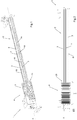
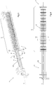
- the separator unit of the invention which is suitable for being used in a cutting line of laminar materials into strips, is depicted as a whole in figures from 1 to 4, where it is indicated as a whole with 1.
- the separator unit 1 comprises an expandable shaft 2, preferably cylindrical in shape, preferably provided with a plurality of expandable means 3 arranged in substantially longitudinal direction along the expandable shaft 2.
- such expandable means 3 known in themselves preferably comprise longitudinal strips with a vulcanized rubber finishing defined on the surface thereof facing outwards, and air chambers arranged between the strips and the shaft 2.
- Such air chambers preferably are operatively connected to a pneumatic source (not shown in the figures) capable of filling the air chambers with a gas, preferably with air.
- such pneumatic source is also configured to allow the emptying of the gas inside the air chambers of the expandable means 3 in expanded configuration when there is a need to extract the separator tools 5 from the expandable shaft 2 or there is a need to modify their arrangement on the shaft 2.
- the expandable means 3 alternatively could be operatively connected to a hydraulic source, of the type in itself known, so long as it is capable of expanding the expandable means 3.
- the aforesaid expandable means 3 could be of the mechanical type.
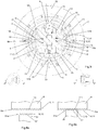
- such expandable means 3 are arranged along the expandable shaft in specific longitudinal housings 18 which are lowered with respect to the outer surface 2a of the expandable shaft 2, as shown in fig. 5 .
- expandable means 3 it is not excluded for such expandable means 3 to be arranged on the outer surface 2a of the expandable shaft 2 without defining the aforesaid longitudinal housings 18, so long as they allow translating the separator tools 5 on the expandable shaft 2 when they are in their non-expanded configuration and they also prevent the movement of the separator tools 5 when they are in expanded configuration.
- the expandable shaft 2 is an expandable shaft of the fixed type. According to an alternative implementation embodiment, it is not excluded for the expandable shaft 2 to be rotating.
- the separator unit 1 of the invention also comprises a storage magazine 4 for storing the aforesaid separator tools 5.
- the storage magazine 4 is operatively associated with an end 2b of the expandable shaft 2.
- it is defined and shaped like an extension of the aforesaid expandable shaft 2 at the aforesaid end 2b of the latter.
- the separator unit 1 of the invention obviously also comprises a plurality of the aforesaid separator tools 5, each of which is provided with a disc 52, preferably annular in shape, of limited thickness, with which a ring 51 , preferably an annular ring, is centrally and axially associated, which is configured to allow the translation of the separator tool 5 from the storage magazine 4 to the expandable shaft 2 in a predefined position, and vice versa.
- a ring 51 preferably an annular ring
- the annular disc 52 of each separator tool 5 is connected to the relative annular ring 51 by means of a mechanical bearing so that the annular disc 52 can rotate relative to the expandable shaft 2 in operating step.
- the annular disc 52 of each separator tool 5 is fixedly associated with the relative annular ring 51 so that the rotation of the expandable shaft 2 results in the rotation of the annular disc 52.
- the separator unit 1 of the invention comprises translation means 4 configured to operate the aforesaid translation of the separator tools 5.
- the expandable shaft 2 is provided with at least a first slit 7, preferably with two first slits 7 made in longitudinal direction along the same expandable shaft 2 and in diametrically opposed position between them.
- Each of the aforesaid first slits 7 is configured to house a locking element 8 having substantially longitudinal development and which has a knurling 9 on its outwards facing surface 8a.
- such locking element 8 is susceptible to translating in radial direction with respect to the longitudinal axis X of the expandable shaft 2.
- such radial translation preferably is actuated by interposing an expandable element 13, even more preferably an air chamber operatively communicating with the aforesaid pneumatic source or with a different pneumatic source with respect to the one of the expandable means 3, between the bottom 7a of each of the aforesaid first slits 7 and the relative locking element 8.
- such expandable element 13 it is not excluded for such expandable element 13 to be of other type, for example mechanical, so long as it is capable of radially translating the locking element 8.
- the number of the aforesaid first slits 7 and of the relative locking elements 8 may be less or greater than two.
- the rings 51 of the aforesaid separator tools 5 have a counter-knurling 10 at one or more lengths, preferably at two lengths defined diametrically opposed to each other, of their surface 51a facing the expandable shaft 2.
- the invention provides for the knurling 9 made on each of the two locking elements 8 to be configured to fixedly couple with one of the two counter-knurlings 10 made on the aforesaid surface 51a of each of the rings 51 of the separator tools 5 when the surfaces 8a of the locking elements 8 are placed in contact with the relative surfaces 51a of the rings 51, as schematically depicted in fig. 6b .
- each knurling 9 and a relative counter-knurling 10 allows ensuring an optimal locking between the expandable shaft 2 and the separator tools 5 arranged on the shaft 2 when it is in expanded configuration.
- knurling 9 and the counter-knurling 10 preferably comprise respectively a toothing 11 and a counter-toothing 12 that are complementary to each other.
- the teeth 111 and 121 of the aforesaid toothing 11 and of the aforesaid counter-toothing 12 are defined in sequence according to a parallel direction with respect to the longitudinal axis X of the expandable shaft 2, as shown in figures 6a and 6b .
- the teeth 111 and 121 of the toothing 11 and of the counter-toothing 12 are defined in sequence according to an orthogonal direction with respect to the longitudinal axis X of the expandable shaft 2.
- such knurling 9 and counter-knurling 10 could be made in the shape of side-by-side diamond tips.
- such translation means 6 preferably are made integrated in the expandable shaft 2 .
- such translation means 6 comprise at least one retractable punch 61 , preferably two retractable punches 61 , arranged in diametrically opposed positions from each other on the expandable shaft 2.
- Such retractable punches 61 are susceptible to being translated in radial direction from a first position, according to which they are at least partially exposed with respect to the outer surface 2a of the expandable shaft 2, to a second position, according to which the retractable punches 61 are completely retracted with respect to the aforesaid outer surface 2a .
- Such translation must occur also in opposite direction.
- the retractable punches 61 are susceptible to translating axially along the expandable shaft 2 through two second slits 14 defined along the expandable shaft 2 and along the storage magazine 4 , so as to allow the picking of a separator tool 5 from the storage magazine 4 and its positioning along the expandable shaft 2 , as shown in detail below.
- each of the two retractable punches 61 is implemented with a belt 62 and pulley 63 transmission system inserted in the expandable shaft 2, as shown in fig. 7 .
- each of the aforesaid retractable punches 61 is operatively associated with a mechanical slide 64 fixed in a point of the aforesaid belt 62.
- the retractable punch 61 With regard to the radial translation of the retractable punch 61 , it is implemented by means of mechanical connection members - in themselves known - between the retractable punch 61 and the relative slide 64.
- the number of retractable punches 61 on the expandable shaft 2 is not excluded for the number of retractable punches 61 on the expandable shaft 2 to be other than two, to be arranged in different positions from the ones described above, or for the axial and radial translation system of the retractable punches 61 to be of alternative type with respect to the one of the preferred implementation embodiment, so long as capable of operating such translations.
- the separator unit 1 of the invention provides for the annular rings 51 of the separator tools 5 to have, on their surfaces 51a , at least one housing 15 , preferably two housings 15 made in diametrically opposed positions from each other, which are configured to house the retractable punches 61 in their first position.
- the number and the position of the housings 15 defined on the rings 51 of the separator tools 5 must correspond with the number and positions of the retractable punches 61 located on the expandable shaft 2.
- the aforesaid translation means 6 are configured to axially translate the retractable punches 61 at one of the separator tools 5, position the retractable punches 61 in their first position, thus coupling with the housings 15 of the ring 51 of the aforesaid separator tool 5, and translate the retractable punches 61 jointly with the separator tool 5 from the storage magazine 4 to a predefined position on the expandable shaft 2.
- the translation means 6 are configured to also execute the inverse translation operation.
- both the free end 61a of each retractable punch 61 and the housings 15 are shaped in the form of a frusto pyramid with radial axis of development with respect to the expandable shaft 2 , and are complementary to each other.
- FIG. 8 A depiction of the aforesaid configuration is shown in fig. 8 with regard to the retractable punch 61.
- the aforesaid shaping of the retractable punches 61 and of the housings 15 jointly with the fact that the two retractable punches 61 are defined in diametrically opposed positions from each other, allows the raising and moving away of the separator tool 5 from the expandable shaft 2 in the release step of the retractable punches 61 and the coupling step thereof with the housings 15.
- this reduces or even eliminates the possibility of contact, and therefore of friction, between the two during the translation step of the separator tool 5 on the expandable shaft 2.
- the frusto-pyramidal form of the retractable punches 61 and of the corresponding housings 15 allows ensuring the perfectly orthogonal positioning of the separator tools 5 with respect to the expandable shaft 2 because the coupling between the corresponding surfaces of the frusto pyramids of the retractable punches 61 and of the relative housings 15 acts as centring system.
- the free end 61a of the retractable punches 61 and the housings 15 could be shaped like a truncated cone with radial axis of development with respect to the expandable shaft 2.
- Such implementation embodiment allows achieving the aforesaid first advantage, but not also the second.
- the separator unit 1 of the invention provides for the rings 51 to comprise at least one centring element 16, preferably two centring elements 16 radially protruding from their surface 51a facing the expandable shaft 2.
- the two centring elements 16 preferably are defined in diametrically opposed positions from each other.
- the expandable shaft 2 comprises at least a third slit 17 , preferably two third slits 17 defined in diametrically opposed positions from each other, having substantially longitudinal development, which are suitable for housing such centring element 16 so as to advantageously prevent the rotation of the separator tools 5 with respect to the expandable shaft 2 .
- the aforesaid third slits 17 correspond to the aforesaid first slits 7 in which there is arranged the locking element 8 and accordingly the counter-knurling 10 of the rings 51 is defined on the surface 16a facing the expandable shaft 2 of the aforesaid centring elements 16.
- the cutting line 100 of the laminar materials into strips, wound on bobbins, in particular of sheets of different thicknesses, widths and lengths, schematically depicted in fig. 9 , is part of the invention.
- such cutting line 100 comprises one or more separator units 1 which characteristics were described above.
- the invention results in a method of arranging and locking a plurality of separator tools 5 along an expandable shaft 2 belonging to the separator unit 1 of the invention.
- a method can provide axially translating the retractable punches 61 at one of the separator tools 5 located in the storage magazine 4.
- the method can provide extracting the retractable punches 61 from the expandable shaft 2 so as to obtain the coupling with the housings 15 of the rings 51 of the aforesaid separator tool 5.
- the method then can provide for translating the retractable punches 61 jointly with the separator tool 5 along the expandable shaft 2 at a predefined position.
- the separator tool 5 being located in such predefined position, the retractable punches 61 are retracted and the aforesaid steps are possibly repeated for further one or more separator tools 5.
- the method provides expanding the expandable means 3 and the expandable elements 13 so that the first ones come in contact directly with the surface 51a of the aforesaid rings 51 , while the second ones allow the locking elements 8 to radially translate outwards up to reaching the stable coupling between the toothings 11 and the relative counter-toothings 12 . It is not excluded for the method to provide the expansion of the expandable elements 13 alone. Due to that mentioned hereto, it is understood that the separator unit described above achieves the preset objects.
- the object is achieved of making a separator unit which, once provided, is capable of ensuring increased stability of its composition with respect to the separator units of the prior art.
- the object of the invention of making a separator unit capable of improving locking the separator tools on the expandable shaft is achieved. Furthermore, the object is achieved of making a separator unit capable of keeping the aforesaid separator tools in an optimal position during the arrangement of the latter on the expandable shaft.
- the object is achieved of making a separator unit which allows facilitating the step of arranging separator tools on the expandable shaft.
- the object is achieved of making a separator unit having reduced sizes with respect to certain types of separator units of the prior art.
Landscapes
- Engineering & Computer Science (AREA)
- Mechanical Engineering (AREA)
- Life Sciences & Earth Sciences (AREA)
- Forests & Forestry (AREA)
- Forms Removed On Construction Sites Or Auxiliary Members Thereof (AREA)
- Winding Of Webs (AREA)
- Fixed Capacitors And Capacitor Manufacturing Machines (AREA)
- Perforating, Stamping-Out Or Severing By Means Other Than Cutting (AREA)
- Cell Separators (AREA)
Priority Applications (1)
| Application Number | Priority Date | Filing Date | Title |
|---|---|---|---|
| PL18712655T PL3585548T3 (pl) | 2017-02-27 | 2018-02-27 | Jednostka separatora do cięcia materiału warstwowego na paski |
Applications Claiming Priority (2)
| Application Number | Priority Date | Filing Date | Title |
|---|---|---|---|
| IT102017000021733A IT201700021733A1 (it) | 2017-02-27 | 2017-02-27 | Gruppo separatore perfezionato particolarmente adatto a venire impiegato in linee di taglio di materiali laminari in nastri e linea di taglio comprendente detto gruppo separatore |
| PCT/IB2018/051238 WO2018154541A1 (en) | 2017-02-27 | 2018-02-27 | Separator unit for cutting laminar material into strips |
Publications (2)
| Publication Number | Publication Date |
|---|---|
| EP3585548A1 EP3585548A1 (en) | 2020-01-01 |
| EP3585548B1 true EP3585548B1 (en) | 2021-10-06 |
Family
ID=59521249
Family Applications (1)
| Application Number | Title | Priority Date | Filing Date |
|---|---|---|---|
| EP18712655.2A Active EP3585548B1 (en) | 2017-02-27 | 2018-02-27 | Separator unit for cutting laminar material into strips |
Country Status (9)
| Country | Link |
|---|---|
| US (1) | US20200009667A1 (pl) |
| EP (1) | EP3585548B1 (pl) |
| CA (1) | CA3054149C (pl) |
| ES (1) | ES2902030T3 (pl) |
| IT (1) | IT201700021733A1 (pl) |
| MX (1) | MX2019010122A (pl) |
| PL (1) | PL3585548T3 (pl) |
| RU (1) | RU2718033C1 (pl) |
| WO (1) | WO2018154541A1 (pl) |
Families Citing this family (1)
| Publication number | Priority date | Publication date | Assignee | Title |
|---|---|---|---|---|
| DE102020109708A1 (de) | 2020-04-07 | 2021-10-07 | Hansella Gmbh | Schneidvorrichtung, Schneidsystem mit der Schneidvorrichtung und Verfahren zum Einstellen eines Schnittabstands |
Family Cites Families (9)
| Publication number | Priority date | Publication date | Assignee | Title |
|---|---|---|---|---|
| US3302506A (en) * | 1964-12-04 | 1967-02-07 | Flynn & Emrich Company | Printer-slotter multiple head lock |
| FR1441546A (fr) * | 1965-03-24 | 1966-06-10 | Arbre porte-couteaux avec dispositif de blocage pneumatique | |
| SU499063A1 (ru) * | 1973-06-28 | 1976-01-15 | Предприятие П/Я В-8570 | Устройство дл безразметной резки листового материала |
| US4237761A (en) * | 1978-05-23 | 1980-12-09 | Molins Machine Company, Inc. | Head locking means for slitter scorer |
| SU1237328A1 (ru) * | 1984-06-29 | 1986-06-15 | Уфимский Нефтяной Институт | Устройство дл продольной резки |
| SU1505685A1 (ru) * | 1987-06-29 | 1989-09-07 | Украинский Государственный Головной Проектно-Изыскательский И Научно-Исследовательский Институт "Укргипроводхоз" | Устройство дл резки листового материала |
| US5803399A (en) * | 1996-11-27 | 1998-09-08 | Japan Development Consultants, Inc. | Expandable shaft |
| US7252261B2 (en) * | 2003-04-07 | 2007-08-07 | Goldenrod Corporation | Ultra-light pneumatic leaf expanding shaft |
| RU2281189C2 (ru) * | 2004-06-16 | 2006-08-10 | Открытое акционерное общество "Магнитогорский металлургический комбинат" | Способ продольной резки движущейся стальной полосы и устройство для его осуществления |
-
2017
- 2017-02-27 IT IT102017000021733A patent/IT201700021733A1/it unknown
-
2018
- 2018-02-27 PL PL18712655T patent/PL3585548T3/pl unknown
- 2018-02-27 EP EP18712655.2A patent/EP3585548B1/en active Active
- 2018-02-27 MX MX2019010122A patent/MX2019010122A/es unknown
- 2018-02-27 WO PCT/IB2018/051238 patent/WO2018154541A1/en not_active Ceased
- 2018-02-27 RU RU2019128711A patent/RU2718033C1/ru active
- 2018-02-27 CA CA3054149A patent/CA3054149C/en active Active
- 2018-02-27 US US16/488,831 patent/US20200009667A1/en not_active Abandoned
- 2018-02-27 ES ES18712655T patent/ES2902030T3/es active Active
Non-Patent Citations (1)
| Title |
|---|
| None * |
Also Published As
| Publication number | Publication date |
|---|---|
| IT201700021733A1 (it) | 2018-08-27 |
| ES2902030T3 (es) | 2022-03-24 |
| MX2019010122A (es) | 2019-10-15 |
| CA3054149C (en) | 2021-06-08 |
| US20200009667A1 (en) | 2020-01-09 |
| WO2018154541A1 (en) | 2018-08-30 |
| PL3585548T3 (pl) | 2022-02-14 |
| RU2718033C1 (ru) | 2020-03-30 |
| CA3054149A1 (en) | 2018-08-30 |
| EP3585548A1 (en) | 2020-01-01 |
| BR112019017615A2 (pt) | 2020-03-24 |
Similar Documents
| Publication | Publication Date | Title |
|---|---|---|
| KR102890167B1 (ko) | 파이프 홈 가공 장치를 위한 파이프 수용 조립체 | |
| EP3441171A1 (en) | Pipe cutting apparatus | |
| US10207311B2 (en) | Machine for the production of coiled gaskets | |
| KR102435653B1 (ko) | 파이프 홈 가공 장치 | |
| EP3461605B1 (en) | Cutting head for a centrifugal cutting apparatus and centrifugal cutting apparatus equipped with same | |
| US9862031B2 (en) | Tube scraper with biased blades | |
| EP3585548B1 (en) | Separator unit for cutting laminar material into strips | |
| US4701989A (en) | Pipe and flange alignment tool | |
| EP3013570B1 (en) | Tyre building drum with a turn-up mechanism | |
| US2595541A (en) | Tool for shaping the ends of conduits | |
| US2893190A (en) | Roll wrapping | |
| EP1150830B1 (en) | Adjustable tire building contour drum and method of building tire thereon | |
| KR101569409B1 (ko) | 링 타입의 절삭 대상물을 다수의 링으로 절단하는 절단장치 | |
| JP5357591B2 (ja) | 丸抜き装置 | |
| KR102343153B1 (ko) | 원형 판금 블랭크로부터 회전대칭적 몸체의 비절삭 제작을 위한 방법 | |
| EP2962842B1 (en) | Method to form a stacking shoulder into the sidewall of a cup with a rotating tool | |
| BR112019017615B1 (pt) | Unidade de separador e linha de corte | |
| CN210308572U (zh) | 一种轮胎自动处理设备 | |
| US2594812A (en) | Buffing wheel | |
| CN222138198U (zh) | 一种纸芯自动夹紧的收放料装置 | |
| US3534645A (en) | Tube cutting apparatus | |
| US3481226A (en) | Tool for relieving air entrapments | |
| CN117086948A (zh) | 一种分切机的上刀夹、上圆刀调整装置 | |
| EP2415568A1 (en) | Counter-die cylinder for a stamping machine | |
| HK40069856A (en) | Pipe grooving device having flared cup |
Legal Events
| Date | Code | Title | Description |
|---|---|---|---|
| STAA | Information on the status of an ep patent application or granted ep patent |
Free format text: STATUS: UNKNOWN |
|
| STAA | Information on the status of an ep patent application or granted ep patent |
Free format text: STATUS: THE INTERNATIONAL PUBLICATION HAS BEEN MADE |
|
| PUAI | Public reference made under article 153(3) epc to a published international application that has entered the european phase |
Free format text: ORIGINAL CODE: 0009012 |
|
| STAA | Information on the status of an ep patent application or granted ep patent |
Free format text: STATUS: REQUEST FOR EXAMINATION WAS MADE |
|
| 17P | Request for examination filed |
Effective date: 20190907 |
|
| AK | Designated contracting states |
Kind code of ref document: A1 Designated state(s): AL AT BE BG CH CY CZ DE DK EE ES FI FR GB GR HR HU IE IS IT LI LT LU LV MC MK MT NL NO PL PT RO RS SE SI SK SM TR |
|
| AX | Request for extension of the european patent |
Extension state: BA ME |
|
| DAV | Request for validation of the european patent (deleted) | ||
| DAX | Request for extension of the european patent (deleted) | ||
| REG | Reference to a national code |
Ref country code: DE Ref legal event code: R079 Ref document number: 602018024618 Country of ref document: DE Free format text: PREVIOUS MAIN CLASS: B23D0035000000 Ipc: B23D0021020000 |
|
| GRAP | Despatch of communication of intention to grant a patent |
Free format text: ORIGINAL CODE: EPIDOSNIGR1 |
|
| RIC1 | Information provided on ipc code assigned before grant |
Ipc: B65H 75/26 20060101ALI20201028BHEP Ipc: B65H 75/24 20060101ALI20201028BHEP Ipc: B65H 75/22 20060101ALI20201028BHEP Ipc: B26D 7/26 20060101ALI20201028BHEP Ipc: B26D 1/24 20060101ALI20201028BHEP Ipc: B23D 35/00 20060101ALI20201028BHEP Ipc: B26D 5/02 20060101ALI20201028BHEP Ipc: B23D 21/02 20060101AFI20201028BHEP Ipc: B65H 75/14 20060101ALI20201028BHEP |
|
| STAA | Information on the status of an ep patent application or granted ep patent |
Free format text: STATUS: GRANT OF PATENT IS INTENDED |
|
| INTG | Intention to grant announced |
Effective date: 20201203 |
|
| RIN1 | Information on inventor provided before grant (corrected) |
Inventor name: PILOT, ANDREA |
|
| GRAJ | Information related to disapproval of communication of intention to grant by the applicant or resumption of examination proceedings by the epo deleted |
Free format text: ORIGINAL CODE: EPIDOSDIGR1 |
|
| STAA | Information on the status of an ep patent application or granted ep patent |
Free format text: STATUS: REQUEST FOR EXAMINATION WAS MADE |
|
| GRAP | Despatch of communication of intention to grant a patent |
Free format text: ORIGINAL CODE: EPIDOSNIGR1 |
|
| STAA | Information on the status of an ep patent application or granted ep patent |
Free format text: STATUS: GRANT OF PATENT IS INTENDED |
|
| INTC | Intention to grant announced (deleted) | ||
| INTG | Intention to grant announced |
Effective date: 20210429 |
|
| GRAS | Grant fee paid |
Free format text: ORIGINAL CODE: EPIDOSNIGR3 |
|
| GRAA | (expected) grant |
Free format text: ORIGINAL CODE: 0009210 |
|
| STAA | Information on the status of an ep patent application or granted ep patent |
Free format text: STATUS: THE PATENT HAS BEEN GRANTED |
|
| AK | Designated contracting states |
Kind code of ref document: B1 Designated state(s): AL AT BE BG CH CY CZ DE DK EE ES FI FR GB GR HR HU IE IS IT LI LT LU LV MC MK MT NL NO PL PT RO RS SE SI SK SM TR |
|
| REG | Reference to a national code |
Ref country code: GB Ref legal event code: FG4D |
|
| REG | Reference to a national code |
Ref country code: CH Ref legal event code: EP Ref country code: AT Ref legal event code: REF Ref document number: 1435791 Country of ref document: AT Kind code of ref document: T Effective date: 20211015 |
|
| REG | Reference to a national code |
Ref country code: IE Ref legal event code: FG4D |
|
| REG | Reference to a national code |
Ref country code: DE Ref legal event code: R096 Ref document number: 602018024618 Country of ref document: DE |
|
| REG | Reference to a national code |
Ref country code: FI Ref legal event code: FGE |
|
| REG | Reference to a national code |
Ref country code: LT Ref legal event code: MG9D Ref country code: SE Ref legal event code: TRGR |
|
| REG | Reference to a national code |
Ref country code: NL Ref legal event code: FP |
|
| REG | Reference to a national code |
Ref country code: AT Ref legal event code: MK05 Ref document number: 1435791 Country of ref document: AT Kind code of ref document: T Effective date: 20211006 |
|
| REG | Reference to a national code |
Ref country code: ES Ref legal event code: FG2A Ref document number: 2902030 Country of ref document: ES Kind code of ref document: T3 Effective date: 20220324 |
|
| PG25 | Lapsed in a contracting state [announced via postgrant information from national office to epo] |
Ref country code: RS Free format text: LAPSE BECAUSE OF FAILURE TO SUBMIT A TRANSLATION OF THE DESCRIPTION OR TO PAY THE FEE WITHIN THE PRESCRIBED TIME-LIMIT Effective date: 20211006 Ref country code: LT Free format text: LAPSE BECAUSE OF FAILURE TO SUBMIT A TRANSLATION OF THE DESCRIPTION OR TO PAY THE FEE WITHIN THE PRESCRIBED TIME-LIMIT Effective date: 20211006 Ref country code: BG Free format text: LAPSE BECAUSE OF FAILURE TO SUBMIT A TRANSLATION OF THE DESCRIPTION OR TO PAY THE FEE WITHIN THE PRESCRIBED TIME-LIMIT Effective date: 20220106 Ref country code: AT Free format text: LAPSE BECAUSE OF FAILURE TO SUBMIT A TRANSLATION OF THE DESCRIPTION OR TO PAY THE FEE WITHIN THE PRESCRIBED TIME-LIMIT Effective date: 20211006 |
|
| REG | Reference to a national code |
Ref country code: FI Ref legal event code: PCE Owner name: OFFICINE M.T.M. S.P.A. |
|
| REG | Reference to a national code |
Ref country code: DE Ref legal event code: R081 Ref document number: 602018024618 Country of ref document: DE Owner name: OFFICINE M.T.M. S.P.A., IT Free format text: FORMER OWNER: KEMA S.R.L. - IN LIQUIDAZIONE, BRENDOLA, IT |
|
| PG25 | Lapsed in a contracting state [announced via postgrant information from national office to epo] |
Ref country code: IS Free format text: LAPSE BECAUSE OF FAILURE TO SUBMIT A TRANSLATION OF THE DESCRIPTION OR TO PAY THE FEE WITHIN THE PRESCRIBED TIME-LIMIT Effective date: 20220206 Ref country code: PT Free format text: LAPSE BECAUSE OF FAILURE TO SUBMIT A TRANSLATION OF THE DESCRIPTION OR TO PAY THE FEE WITHIN THE PRESCRIBED TIME-LIMIT Effective date: 20220207 Ref country code: NO Free format text: LAPSE BECAUSE OF FAILURE TO SUBMIT A TRANSLATION OF THE DESCRIPTION OR TO PAY THE FEE WITHIN THE PRESCRIBED TIME-LIMIT Effective date: 20220106 Ref country code: LV Free format text: LAPSE BECAUSE OF FAILURE TO SUBMIT A TRANSLATION OF THE DESCRIPTION OR TO PAY THE FEE WITHIN THE PRESCRIBED TIME-LIMIT Effective date: 20211006 Ref country code: HR Free format text: LAPSE BECAUSE OF FAILURE TO SUBMIT A TRANSLATION OF THE DESCRIPTION OR TO PAY THE FEE WITHIN THE PRESCRIBED TIME-LIMIT Effective date: 20211006 Ref country code: GR Free format text: LAPSE BECAUSE OF FAILURE TO SUBMIT A TRANSLATION OF THE DESCRIPTION OR TO PAY THE FEE WITHIN THE PRESCRIBED TIME-LIMIT Effective date: 20220107 |
|
| REG | Reference to a national code |
Ref country code: LU Ref legal event code: PD Owner name: OFFICINE M.T.M. S.P.A.; IT Free format text: FORMER OWNER: KEMA S.R.L. - IN LIQUIDAZIONE Effective date: 20220519 |
|
| REG | Reference to a national code |
Ref country code: NL Ref legal event code: PD Owner name: OFFICINE M.T.M. S.P.A.; IT Free format text: DETAILS ASSIGNMENT: CHANGE OF OWNER(S), ASSIGNMENT; FORMER OWNER NAME: KEMA S.R.L. - IN LIQUIDAZIONE Effective date: 20220613 |
|
| REG | Reference to a national code |
Ref country code: BE Ref legal event code: PD Owner name: OFFICINE M.T.M. S.P.A.; IT Free format text: DETAILS ASSIGNMENT: CHANGE OF OWNER(S), ASSIGNMENT; FORMER OWNER NAME: KEMA S.R.L. - IN LIQUIDAZIONE Effective date: 20220524 |
|
| REG | Reference to a national code |
Ref country code: ES Ref legal event code: PC2A Owner name: OFFICINE M.T.M. S.P.A. Effective date: 20220628 |
|
| REG | Reference to a national code |
Ref country code: DE Ref legal event code: R097 Ref document number: 602018024618 Country of ref document: DE |
|
| PG25 | Lapsed in a contracting state [announced via postgrant information from national office to epo] |
Ref country code: SM Free format text: LAPSE BECAUSE OF FAILURE TO SUBMIT A TRANSLATION OF THE DESCRIPTION OR TO PAY THE FEE WITHIN THE PRESCRIBED TIME-LIMIT Effective date: 20211006 Ref country code: SK Free format text: LAPSE BECAUSE OF FAILURE TO SUBMIT A TRANSLATION OF THE DESCRIPTION OR TO PAY THE FEE WITHIN THE PRESCRIBED TIME-LIMIT Effective date: 20211006 Ref country code: RO Free format text: LAPSE BECAUSE OF FAILURE TO SUBMIT A TRANSLATION OF THE DESCRIPTION OR TO PAY THE FEE WITHIN THE PRESCRIBED TIME-LIMIT Effective date: 20211006 Ref country code: EE Free format text: LAPSE BECAUSE OF FAILURE TO SUBMIT A TRANSLATION OF THE DESCRIPTION OR TO PAY THE FEE WITHIN THE PRESCRIBED TIME-LIMIT Effective date: 20211006 Ref country code: DK Free format text: LAPSE BECAUSE OF FAILURE TO SUBMIT A TRANSLATION OF THE DESCRIPTION OR TO PAY THE FEE WITHIN THE PRESCRIBED TIME-LIMIT Effective date: 20211006 Ref country code: CZ Free format text: LAPSE BECAUSE OF FAILURE TO SUBMIT A TRANSLATION OF THE DESCRIPTION OR TO PAY THE FEE WITHIN THE PRESCRIBED TIME-LIMIT Effective date: 20211006 |
|
| PLBE | No opposition filed within time limit |
Free format text: ORIGINAL CODE: 0009261 |
|
| STAA | Information on the status of an ep patent application or granted ep patent |
Free format text: STATUS: NO OPPOSITION FILED WITHIN TIME LIMIT |
|
| 26N | No opposition filed |
Effective date: 20220707 |
|
| PG25 | Lapsed in a contracting state [announced via postgrant information from national office to epo] |
Ref country code: MC Free format text: LAPSE BECAUSE OF FAILURE TO SUBMIT A TRANSLATION OF THE DESCRIPTION OR TO PAY THE FEE WITHIN THE PRESCRIBED TIME-LIMIT Effective date: 20211006 |
|
| REG | Reference to a national code |
Ref country code: CH Ref legal event code: PL |
|
| GBPC | Gb: european patent ceased through non-payment of renewal fee |
Effective date: 20220227 |
|
| PG25 | Lapsed in a contracting state [announced via postgrant information from national office to epo] |
Ref country code: AL Free format text: LAPSE BECAUSE OF FAILURE TO SUBMIT A TRANSLATION OF THE DESCRIPTION OR TO PAY THE FEE WITHIN THE PRESCRIBED TIME-LIMIT Effective date: 20211006 |
|
| PG25 | Lapsed in a contracting state [announced via postgrant information from national office to epo] |
Ref country code: SI Free format text: LAPSE BECAUSE OF FAILURE TO SUBMIT A TRANSLATION OF THE DESCRIPTION OR TO PAY THE FEE WITHIN THE PRESCRIBED TIME-LIMIT Effective date: 20211006 |
|
| PG25 | Lapsed in a contracting state [announced via postgrant information from national office to epo] |
Ref country code: FR Free format text: LAPSE BECAUSE OF NON-PAYMENT OF DUE FEES Effective date: 20220228 |
|
| PG25 | Lapsed in a contracting state [announced via postgrant information from national office to epo] |
Ref country code: LI Free format text: LAPSE BECAUSE OF NON-PAYMENT OF DUE FEES Effective date: 20220228 Ref country code: IE Free format text: LAPSE BECAUSE OF NON-PAYMENT OF DUE FEES Effective date: 20220227 Ref country code: GB Free format text: LAPSE BECAUSE OF NON-PAYMENT OF DUE FEES Effective date: 20220227 Ref country code: CH Free format text: LAPSE BECAUSE OF NON-PAYMENT OF DUE FEES Effective date: 20220228 |
|
| PG25 | Lapsed in a contracting state [announced via postgrant information from national office to epo] |
Ref country code: MK Free format text: LAPSE BECAUSE OF FAILURE TO SUBMIT A TRANSLATION OF THE DESCRIPTION OR TO PAY THE FEE WITHIN THE PRESCRIBED TIME-LIMIT Effective date: 20211006 Ref country code: CY Free format text: LAPSE BECAUSE OF FAILURE TO SUBMIT A TRANSLATION OF THE DESCRIPTION OR TO PAY THE FEE WITHIN THE PRESCRIBED TIME-LIMIT Effective date: 20211006 |
|
| PG25 | Lapsed in a contracting state [announced via postgrant information from national office to epo] |
Ref country code: HU Free format text: LAPSE BECAUSE OF FAILURE TO SUBMIT A TRANSLATION OF THE DESCRIPTION OR TO PAY THE FEE WITHIN THE PRESCRIBED TIME-LIMIT; INVALID AB INITIO Effective date: 20180227 |
|
| PG25 | Lapsed in a contracting state [announced via postgrant information from national office to epo] |
Ref country code: MT Free format text: LAPSE BECAUSE OF FAILURE TO SUBMIT A TRANSLATION OF THE DESCRIPTION OR TO PAY THE FEE WITHIN THE PRESCRIBED TIME-LIMIT Effective date: 20211006 |
|
| PGFP | Annual fee paid to national office [announced via postgrant information from national office to epo] |
Ref country code: DE Payment date: 20250218 Year of fee payment: 8 |
|
| PGFP | Annual fee paid to national office [announced via postgrant information from national office to epo] |
Ref country code: FI Payment date: 20250220 Year of fee payment: 8 |
|
| PGFP | Annual fee paid to national office [announced via postgrant information from national office to epo] |
Ref country code: SE Payment date: 20250218 Year of fee payment: 8 |
|
| PGFP | Annual fee paid to national office [announced via postgrant information from national office to epo] |
Ref country code: BE Payment date: 20250218 Year of fee payment: 8 |
|
| PGFP | Annual fee paid to national office [announced via postgrant information from national office to epo] |
Ref country code: PL Payment date: 20250213 Year of fee payment: 8 |
|
| PGFP | Annual fee paid to national office [announced via postgrant information from national office to epo] |
Ref country code: IT Payment date: 20241127 Year of fee payment: 8 |
|
| PGFP | Annual fee paid to national office [announced via postgrant information from national office to epo] |
Ref country code: ES Payment date: 20250331 Year of fee payment: 8 |
|
| PG25 | Lapsed in a contracting state [announced via postgrant information from national office to epo] |
Ref country code: TR Free format text: LAPSE BECAUSE OF FAILURE TO SUBMIT A TRANSLATION OF THE DESCRIPTION OR TO PAY THE FEE WITHIN THE PRESCRIBED TIME-LIMIT Effective date: 20211006 |
|
| PGFP | Annual fee paid to national office [announced via postgrant information from national office to epo] |
Ref country code: LU Payment date: 20260218 Year of fee payment: 9 Ref country code: NL Payment date: 20260218 Year of fee payment: 9 |