EP3584520B1 - Fluidregelungssystem - Google Patents
Fluidregelungssystem Download PDFInfo
- Publication number
- EP3584520B1 EP3584520B1 EP19179692.9A EP19179692A EP3584520B1 EP 3584520 B1 EP3584520 B1 EP 3584520B1 EP 19179692 A EP19179692 A EP 19179692A EP 3584520 B1 EP3584520 B1 EP 3584520B1
- Authority
- EP
- European Patent Office
- Prior art keywords
- fluid
- phase
- outlet
- control system
- accumulator
- Prior art date
- Legal status (The legal status is an assumption and is not a legal conclusion. Google has not performed a legal analysis and makes no representation as to the accuracy of the status listed.)
- Active
Links
Images
Classifications
-
- B—PERFORMING OPERATIONS; TRANSPORTING
- B01—PHYSICAL OR CHEMICAL PROCESSES OR APPARATUS IN GENERAL
- B01D—SEPARATION
- B01D19/00—Degasification of liquids
- B01D19/0042—Degasification of liquids modifying the liquid flow
- B01D19/0052—Degasification of liquids modifying the liquid flow in rotating vessels, vessels containing movable parts or in which centrifugal movement is caused
- B01D19/0057—Degasification of liquids modifying the liquid flow in rotating vessels, vessels containing movable parts or in which centrifugal movement is caused the centrifugal movement being caused by a vortex, e.g. using a cyclone, or by a tangential inlet
-
- F—MECHANICAL ENGINEERING; LIGHTING; HEATING; WEAPONS; BLASTING
- F25—REFRIGERATION OR COOLING; COMBINED HEATING AND REFRIGERATION SYSTEMS; HEAT PUMP SYSTEMS; MANUFACTURE OR STORAGE OF ICE; LIQUEFACTION SOLIDIFICATION OF GASES
- F25B—REFRIGERATION MACHINES, PLANTS OR SYSTEMS; COMBINED HEATING AND REFRIGERATION SYSTEMS; HEAT PUMP SYSTEMS
- F25B43/00—Arrangements for separating or purifying gases or liquids; Arrangements for vaporising the residuum of liquid refrigerant, e.g. by heat
- F25B43/04—Arrangements for separating or purifying gases or liquids; Arrangements for vaporising the residuum of liquid refrigerant, e.g. by heat for withdrawing non-condensible gases
- F25B43/043—Arrangements for separating or purifying gases or liquids; Arrangements for vaporising the residuum of liquid refrigerant, e.g. by heat for withdrawing non-condensible gases for compression type systems
-
- B—PERFORMING OPERATIONS; TRANSPORTING
- B01—PHYSICAL OR CHEMICAL PROCESSES OR APPARATUS IN GENERAL
- B01D—SEPARATION
- B01D17/00—Separation of liquids, not provided for elsewhere, e.g. by thermal diffusion
- B01D17/02—Separation of non-miscible liquids
- B01D17/0217—Separation of non-miscible liquids by centrifugal force
-
- B—PERFORMING OPERATIONS; TRANSPORTING
- B01—PHYSICAL OR CHEMICAL PROCESSES OR APPARATUS IN GENERAL
- B01D—SEPARATION
- B01D17/00—Separation of liquids, not provided for elsewhere, e.g. by thermal diffusion
- B01D17/12—Auxiliary equipment particularly adapted for use with liquid-separating apparatus, e.g. control circuits
-
- B—PERFORMING OPERATIONS; TRANSPORTING
- B01—PHYSICAL OR CHEMICAL PROCESSES OR APPARATUS IN GENERAL
- B01D—SEPARATION
- B01D45/00—Separating dispersed particles from gases or vapours by gravity, inertia, or centrifugal forces
- B01D45/12—Separating dispersed particles from gases or vapours by gravity, inertia, or centrifugal forces by centrifugal forces
-
- B—PERFORMING OPERATIONS; TRANSPORTING
- B04—CENTRIFUGAL APPARATUS OR MACHINES FOR CARRYING-OUT PHYSICAL OR CHEMICAL PROCESSES
- B04C—APPARATUS USING FREE VORTEX FLOW, e.g. CYCLONES
- B04C3/00—Apparatus in which the axial direction of the vortex flow following a screw-thread type line remains unchanged ; Devices in which one of the two discharge ducts returns centrally through the vortex chamber, a reverse-flow vortex being prevented by bulkheads in the central discharge duct
- B04C3/06—Construction of inlets or outlets to the vortex chamber
-
- F—MECHANICAL ENGINEERING; LIGHTING; HEATING; WEAPONS; BLASTING
- F25—REFRIGERATION OR COOLING; COMBINED HEATING AND REFRIGERATION SYSTEMS; HEAT PUMP SYSTEMS; MANUFACTURE OR STORAGE OF ICE; LIQUEFACTION SOLIDIFICATION OF GASES
- F25B—REFRIGERATION MACHINES, PLANTS OR SYSTEMS; COMBINED HEATING AND REFRIGERATION SYSTEMS; HEAT PUMP SYSTEMS
- F25B43/00—Arrangements for separating or purifying gases or liquids; Arrangements for vaporising the residuum of liquid refrigerant, e.g. by heat
-
- F—MECHANICAL ENGINEERING; LIGHTING; HEATING; WEAPONS; BLASTING
- F25—REFRIGERATION OR COOLING; COMBINED HEATING AND REFRIGERATION SYSTEMS; HEAT PUMP SYSTEMS; MANUFACTURE OR STORAGE OF ICE; LIQUEFACTION SOLIDIFICATION OF GASES
- F25B—REFRIGERATION MACHINES, PLANTS OR SYSTEMS; COMBINED HEATING AND REFRIGERATION SYSTEMS; HEAT PUMP SYSTEMS
- F25B43/00—Arrangements for separating or purifying gases or liquids; Arrangements for vaporising the residuum of liquid refrigerant, e.g. by heat
- F25B43/006—Accumulators
-
- B—PERFORMING OPERATIONS; TRANSPORTING
- B01—PHYSICAL OR CHEMICAL PROCESSES OR APPARATUS IN GENERAL
- B01D—SEPARATION
- B01D53/00—Separation of gases or vapours; Recovering vapours of volatile solvents from gases; Chemical or biological purification of waste gases, e.g. engine exhaust gases, smoke, fumes, flue gases, aerosols
- B01D53/24—Separation of gases or vapours; Recovering vapours of volatile solvents from gases; Chemical or biological purification of waste gases, e.g. engine exhaust gases, smoke, fumes, flue gases, aerosols by centrifugal force
-
- F—MECHANICAL ENGINEERING; LIGHTING; HEATING; WEAPONS; BLASTING
- F25—REFRIGERATION OR COOLING; COMBINED HEATING AND REFRIGERATION SYSTEMS; HEAT PUMP SYSTEMS; MANUFACTURE OR STORAGE OF ICE; LIQUEFACTION SOLIDIFICATION OF GASES
- F25B—REFRIGERATION MACHINES, PLANTS OR SYSTEMS; COMBINED HEATING AND REFRIGERATION SYSTEMS; HEAT PUMP SYSTEMS
- F25B2341/00—Details of ejectors not being used as compression device; Details of flow restrictors or expansion valves
- F25B2341/001—Ejectors not being used as compression device
- F25B2341/0012—Ejectors with the cooled primary flow at high pressure
-
- F—MECHANICAL ENGINEERING; LIGHTING; HEATING; WEAPONS; BLASTING
- F25—REFRIGERATION OR COOLING; COMBINED HEATING AND REFRIGERATION SYSTEMS; HEAT PUMP SYSTEMS; MANUFACTURE OR STORAGE OF ICE; LIQUEFACTION SOLIDIFICATION OF GASES
- F25B—REFRIGERATION MACHINES, PLANTS OR SYSTEMS; COMBINED HEATING AND REFRIGERATION SYSTEMS; HEAT PUMP SYSTEMS
- F25B2400/00—Component parts or details not otherwise provided for in this subclass
- F25B2400/02—Centrifugal separation of gas, liquid or oil
-
- F—MECHANICAL ENGINEERING; LIGHTING; HEATING; WEAPONS; BLASTING
- F25—REFRIGERATION OR COOLING; COMBINED HEATING AND REFRIGERATION SYSTEMS; HEAT PUMP SYSTEMS; MANUFACTURE OR STORAGE OF ICE; LIQUEFACTION SOLIDIFICATION OF GASES
- F25B—REFRIGERATION MACHINES, PLANTS OR SYSTEMS; COMBINED HEATING AND REFRIGERATION SYSTEMS; HEAT PUMP SYSTEMS
- F25B2400/00—Component parts or details not otherwise provided for in this subclass
- F25B2400/23—Separators
Definitions
- the present invention generally concerns fluid control systems suitable for use in a gas separating system
- Document DE112014004349T5 shows an exemplary prior art system which includes a fluid control system outputting a first and a second phase of a fluid from a separator.
- Document US2014/196494A1 discloses the use of an eductor in a fluid system.
- Documents US 2007/193285A1 and WO2015/020719A1 generally show the separation of non-condensible gases in fluid control systems.
- Some fluid control systems may be provided with liquid pumps that may encounter difficulties should a gas be present within the liquid. Should the gas encounter the liquid pump, partial loss or total loss of the pump performance may occur.
- the present invention concerns a fluid control system that inter alia includes a vortex separator, a fluid pump, an eductor, and an accumulator.
- the vortex separator has a fluid inlet arranged to receive a fluid, a first fluid outlet arranged output a first phase of the fluid, and a second fluid outlet arranged to output at least one of a non-condensable gas and a second phase of the fluid.
- the fluid pump has a pump outlet and a pump inlet that is fluidly connected to the first fluid outlet.
- the eductor has a first eductor inlet fluidly connected to the pump outlet, a second eductor inlet fluidly connected to the second fluid outlet, and an eductor outlet.
- the accumulator has an accumulator inlet fluidly connected to the eductor outlet and an accumulator outlet fluidly connected to the fluid inlet.
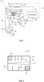
- a fluid control system 10 is provided.
- the fluid control system 10 is closed-loop system that may, during its operation, contain unwanted gas.
- the fluid control system 10 is provided with or in communication with at least a portion of an environmental control system 12.
- the environmental control system 12 may include an evaporator 20 having an inlet 22 that receives a fluid and a condenser 24 having an outlet 26 that outputs the fluid.
- the evaporator 20 having the inlet 22 receives the fluid, which may be in a first phase, such as a liquid phase.
- the evaporator 20 may output the fluid in a second phase, such as, or comprising, a gas phase, a non-condensable gas, or a vapor phase, to the condenser 24.
- the condenser 24 may then condense the second phase back to the first phase, e.g. the liquid phase.
- the second phase may not completely condense back to the first phase in the condenser 24 such that gas or vapor may be present within the fluid making the fluid a two-phase fluid having both the first phase and the second phase present after it exits the condenser 24 through the outlet 26.
- non-condensable gases may be present within the fluid, also resulting in a two-phase fluid.
- the fluid control system 10 of the embodiment is arranged to separate a gas or vapor from the fluid (e.g. working fluid) that flows through the fluid control system 10 and subsequently store the gas or vapor to prevent challenges to a fluid pump, due to the presence of the gas or vapor.
- the fluid control system 10 is provided as a closed loop fluid control system in a device that is capable of operation within a 0G (zero gravity) or low gravity environment.
- the fluid control system 10 includes a vortex separator 30, a fluid pump 32, an eductor 34, and an accumulator 36, where at least all features of appended independent claim 1 are provided.
- vortex separator 30 and the eductor 34 may be passive components that are operated by fluid energy already imparted to the fluid by the fluid pump 32 without an additional pump, driving source, or moving parts provided with the vortex separator 30 or the eductor 34. In such an arrangement, there is no additional power source provided with the fluid control system 10 other than the fluid pump 32.
- the vortex separator 30 includes a separator body 40 that extends between a first end 42 and a second end 44, a series of baffles 46 that are disposed within the separator body 40, and a passageway 48 that extends through the series of baffles 46.
- the separator body 40 defines a fluid inlet 50, a first fluid outlet 52, and a second fluid outlet 54.
- the fluid inlet 50 is disposed proximate the first end 42.
- the fluid inlet 50 may be at least partially defined within or by the separator body 40 and the first end 42.
- the fluid inlet 50 is arranged to receive a fluid, such as the two-phase fluid, from the outlet 26 of the environmental control system 12.
- the first fluid outlet 52 is disposed proximate the second end 44.
- the first fluid outlet 52 may be at least partially defined within or defined by the separator body 40 and the second end 44.
- the first fluid outlet 52 is arranged to output a first phase of the fluid to the fluid pump 32.
- the second fluid outlet 54 is at least partially defined by or is defined by the second end 44 of the separator body 40.
- the passageway 48 receives a second phase of the fluid that is separated from the fluid by the series of baffles 46.
- the passageway 48 directs the second phase of the fluid towards the second fluid outlet 54.
- the second fluid outlet 54 is arranged to output the second phase of the fluid to the eductor 34.
- the fluid pump 32 includes a pump inlet 60 and a pump outlet 62.
- the pump inlet 60 is fluidly connected to the first fluid outlet 52 of the vortex separator 30 by a conduit 64 that extends between the vortex separator 30 and the fluid pump 32.
- the fluid pump 32 is arranged as a liquid pump that provides the first phase of the liquid to the evaporator 20 of the environmental control system 12 through a first pump outlet conduit 66 that extends between the inlet 22 of the environmental control system 12 and the pump outlet 62.
- the fluid pump 32 provides the first phase of the liquid to the eductor 34 through a second pump outlet conduit 68 that may extend from the first pump outlet conduit 66 or may extend from the pump outlet 62.
- the second pump outlet conduit 68 extends between the pump outlet 62 and an inlet of the eductor 34.
- the eductor 34 includes a first eductor inlet 80, a second eductor inlet 82, and an eductor outlet 84.
- the first eductor inlet 80 is arranged to receive the first phase of the fluid from the fluid pump 32 through the second pump outlet conduit 68.
- the second eductor inlet 82 is arranged to receive the first phase of the fluid from the second fluid outlet 54 of the vortex separator 30 through a conduit 86.
- the conduit 86 extends between the second fluid outlet 54 of the vortex separator 30 and the second eductor inlet 82.
- the eductor 34 is arranged to entrain the second phase of the fluid from the vortex separator 30 with the first phase of the fluid from the fluid pump 32.
- the entrained second phase with the first phase of the fluid is output by the eductor 34 through the eductor outlet 84 to the accumulator 36 through another conduit or directly to the accumulator 36.
- the eductor 34 is robust such that if the second phase or secondary fluid is all liquid, all gas/vapor, or a mixture of the aforementioned.
- the eductor 34 is arranged to continue to pump or flow the second phase or secondary fluid with varying flow rates based on the second phase or secondary fluid.
- the accumulator 36 is arranged to receive and store the second phase of the fluid and provide the first phase of the fluid back to the vortex separator 30.
- the accumulator 36 includes an accumulator body 90 that extends between a first accumulator end 92 and a second accumulator end 94.
- the accumulator body 90 encloses or defines a storage container 96 and a flow-through chamber 98 that are separated from each other by a porous barrier 100.
- An accumulator inlet 110 is defined proximate or by the first accumulator end 92.
- the accumulator inlet 110 is fluidly connected to the eductor outlet 84.
- the accumulator inlet 110 is arranged to receive the entrained second phase with the first phase of the fluid that is output by the eductor 34.
- the porous barrier 100 is arranged to separate the first phase of the fluid (e.g. a liquid) from the second phase of the fluid (e.g. a gas or vapor).
- the porous barrier 100 is arranged to separate the entrained second phase of the fluid from the first phase of the fluid and facilitates the trapping/storage/isolation of the second phase of the fluid within the storage container 96.
- the storage container 96 isolates the second phase of the fluid from the remainder of the fluid control system 10.
- the storage container 96 serves as a non-condensable gas storage container.
- the first phase of the fluid is separated from the second phase of the fluid by the porous barrier 100 and flows through the flow-through chamber 98 and through an accumulator outlet 112.
- the accumulator outlet 112 is defined proximate or by the second accumulator end 94.
- the accumulator outlet 112 is fluidly connected to the fluid inlet 50 of the vortex separator 30 through a conduit 114 and is arranged to output the first phase of the fluid to the fluid inlet 50 of the vortex separator 30.
- the conduit 114 outputs the first phase of the fluid into a conduit 120 that extends between the outlet 26 of the environmental control system 12 and the fluid inlet 50 of the vortex separator 30.
- the conduit 120 directs the two phase fluid from the condenser 24 towards the vortex separator 30 and receives the first phase of the fluid from the accumulator 36.
- the accumulator 36 may be arranged as a secondary condenser should the second phase of the liquid be a vapor. In such an embodiment, the accumulator 36 may be arranged to remove heat such that the vapor may be condensed to a liquid within the accumulator 36 and rejoin the primary flow path of the liquid through the accumulator outlet 112.
- the lack of moving parts provided with the vortex separator 30 and the eductor 34 improves the reliability and life of the fluid control system 10. Furthermore, the fluid control system 10 employs passive controls without actuated valves or other active controls.
- the fluid control system 10 of the present disclosure is arranged to separate and store gas/vapor from a liquid in a zero gravity or micro gravity environment (e.g. not gravity dependent).
- the fluid control system 10 of the present disclosure performs without an external vent or overboard vent. The lack of the external vent or overboard vent eliminates a potential fluid leakage path where the closed loop could lose fluid.
Landscapes
- Chemical & Material Sciences (AREA)
- Engineering & Computer Science (AREA)
- Chemical Kinetics & Catalysis (AREA)
- Physics & Mathematics (AREA)
- Thermal Sciences (AREA)
- Analytical Chemistry (AREA)
- Power Engineering (AREA)
- Mechanical Engineering (AREA)
- General Engineering & Computer Science (AREA)
- Jet Pumps And Other Pumps (AREA)
Claims (12)
- Fluidregelungssystem (10), umfassend:einen Wirbelabscheider (30) mit einem Fluideinlass, der angeordnet ist, um ein Fluid aufzunehmen, einem ersten Fluidauslass, der angeordnet ist, um eine erste Phase des Fluids auszugeben, und einem zweiten Fluidauslass, der angeordnet ist, um mindestens eines aus einem nichtkondensierbaren Gas und einer zweiten Phase des Fluids auszugeben;eine Fluidpumpe (32) mit einem Pumpenauslass und einem Pumpeneinlass, der fluidisch mit dem ersten Fluidauslass verbunden ist; und dadurch gekennzeichnet, dass es ferner Folgendes umfasst:einen Eduktor (34) mit einem ersten Eduktoreinlass, der fluidisch mit dem Pumpenauslass verbunden ist, der zum Aufnehmen der ersten Phase des Fluids von der Fluidpumpe (32) konfiguriert ist, und einem zweiten Eduktoreinlass, der fluidisch mit dem zweiten Fluidauslass verbunden ist, der zum Aufnehmen der zweiten Phase des Fluids von dem Wirbelabscheider (30) konfiguriert ist, und einem Eduktorauslass; undeinen Akkumulator (36) mit einem Akkumulatoreinlass, der fluidisch mit dem Eduktorauslass verbunden ist, und einem Akkumulatorauslass, der fluidisch mit dem Fluideinlass verbunden ist;wobei der Akkumulator (36) einen Akkumulatorkörper (90) beinhaltet, der einen Speicherbehälter (96) für nichtkondensierbares Gas und eine Durchflusskammer (98) definiert, die durch eine poröse Barriere (100) voneinander getrennt sind;wobei die poröse Barriere (100) angeordnet ist, um die mitgeführte zweite Phase des Fluids von der ersten Phase des Fluids abzuscheiden, und das Einfangen/Speichern/Isolieren der zweiten Phase des Fluids innerhalb des Speicherbehälters (96) erleichtert.
- Fluidregelungssystem nach Anspruch 1, wobei die erste Phase des Fluids eine flüssige Phase ist.
- Fluidregelungssystem nach Anspruch 1 oder 2, wobei die zweite Phase des Fluids mindestens eines aus einem Gas und einem Dampf ist.
- Fluidregelungssystem nach Anspruch 1, 2 oder 3, wobei der Eduktor (34) angeordnet ist, um die zweite Phase des Fluids innerhalb der ersten Phase des Fluids mitzuführen.
- Fluidregelungssystem nach Anspruch 4, wobei der Akkumulator (36) angeordnet ist, um die mitgeführte zweite Phase des Fluids von der ersten Phase des Fluids abzuscheiden.
- Fluidregelungssystem nach Anspruch 4, wobei der Akkumulator (36) angeordnet ist, um die zweite Phase des Fluids aufzunehmen und zu speichern und dem Fluideinlass die erste Phase des Fluids bereitzustellen.
- Gasabscheidesystem, das mit dem Fluidregelungssystem nach Anspruch 1 bereitgestellt ist, umfassend:
den Wirbelabscheider (30) mit dem Fluideinlass, der angeordnet ist, um das Fluid von einem Umgebungsregelungssystem aufzunehmen. - Gasabscheidesystem nach Anspruch 7, wobei der Wirbelabscheider (30) eine Reihe von Leitblechen (46) beinhaltet, die innerhalb eines Abscheidekörpers (40) angeordnet ist, um die erste Phase von der zweiten Phase abzuscheiden.
- Gasabscheidesystem nach Anspruch 8, wobei sich der Abscheidekörper (40) zwischen einem ersten Ende und einem zweiten Ende erstreckt.
- Gasabscheidesystem nach Anspruch 9, wobei der Fluideinlass in der Nähe des ersten Endes angeordnet ist.
- Gasabscheidesystem nach Anspruch 9, wobei der erste Fluidauslass in der Nähe des zweiten Endes angeordnet ist.
- Gasabscheidesystem nach Anspruch 9, wobei der zweite Fluidauslass mindestens teilweise durch das zweite Ende definiert ist.
Applications Claiming Priority (1)
| Application Number | Priority Date | Filing Date | Title |
|---|---|---|---|
| US16/011,149 US11027223B2 (en) | 2018-06-18 | 2018-06-18 | Fluid control system having a gas separating system |
Publications (2)
| Publication Number | Publication Date |
|---|---|
| EP3584520A1 EP3584520A1 (de) | 2019-12-25 |
| EP3584520B1 true EP3584520B1 (de) | 2023-08-30 |
Family
ID=66826926
Family Applications (1)
| Application Number | Title | Priority Date | Filing Date |
|---|---|---|---|
| EP19179692.9A Active EP3584520B1 (de) | 2018-06-18 | 2019-06-12 | Fluidregelungssystem |
Country Status (2)
| Country | Link |
|---|---|
| US (1) | US11027223B2 (de) |
| EP (1) | EP3584520B1 (de) |
Family Cites Families (7)
| Publication number | Priority date | Publication date | Assignee | Title |
|---|---|---|---|---|
| US4848987A (en) | 1988-08-16 | 1989-07-18 | Administrator, National Aeronautics And Space Administration | Vortex motion phase separator for zero gravity liquid transfer |
| US20070193285A1 (en) | 2006-02-21 | 2007-08-23 | Knight Paul A | Testing for Leaks in a Two-Phase Liquid Cooling System |
| US7931719B2 (en) * | 2007-12-03 | 2011-04-26 | National Tank Company | Revolution vortex tube gas/liquids separator |
| US8978399B2 (en) * | 2013-01-14 | 2015-03-17 | Serguei A. Popov | Heat pumping unit and variants thereof |
| US9879663B2 (en) | 2013-03-01 | 2018-01-30 | Advanced Cooling Technologies, Inc. | Multi-phase pump system and method of pumping a two-phase fluid stream |
| US9987568B2 (en) | 2013-08-09 | 2018-06-05 | Carrier Corporation | Purge system for chiller system |
| JP6248499B2 (ja) * | 2013-09-23 | 2017-12-20 | 株式会社デンソー | エジェクタ式冷凍サイクル |
-
2018
- 2018-06-18 US US16/011,149 patent/US11027223B2/en active Active
-
2019
- 2019-06-12 EP EP19179692.9A patent/EP3584520B1/de active Active
Also Published As
| Publication number | Publication date |
|---|---|
| EP3584520A1 (de) | 2019-12-25 |
| US20190381426A1 (en) | 2019-12-19 |
| US11027223B2 (en) | 2021-06-08 |
Similar Documents
| Publication | Publication Date | Title |
|---|---|---|
| US9669346B2 (en) | Compressor system and oil separation system | |
| ATE388748T1 (de) | Gas/flüssigkeits-abscheider | |
| WO2005124464A3 (en) | Vacuum system for immersion photolithography | |
| EP2218870A3 (de) | Verfahren und Vorrichtung zur Zentrifugaltrennung | |
| WO2006083445A3 (en) | Liquid-vapor separator for a minichannel heat exchanger | |
| WO2009152015A3 (en) | Integrated flow separator and pump-down volume device for use in a heat exchanger | |
| JP2014508644A (ja) | 液体脱気システム内の浸透気化を制御する装置 | |
| MY150471A (en) | Separation system and method | |
| US11027223B2 (en) | Fluid control system having a gas separating system | |
| US7578870B2 (en) | Fluid separating device | |
| EP3412256B1 (de) | Urinsamml- und aufbewahrungsapparat für mikrogravitation | |
| GB2239676A (en) | Pumping gas/liquid mixtures | |
| US4929347A (en) | Concentrating apparatus with reverse osmosis membrane | |
| EP3712542A1 (de) | Ölabscheider und kältekreislaufvorrichtung | |
| JP2015190726A (ja) | フラッシュ蒸気発生装置及びボイラシステム | |
| EP2776720B1 (de) | Kompaktes turbomaschinensystem mit verbesserter dampfströmungshandhabung | |
| EP3426887B1 (de) | Schlammpumpe und vakuumgasextraktionssystem | |
| GB2596018A (en) | Thermal desorption of oily solids | |
| WO2013173257A4 (en) | Dissolved air flotations system with energy recovery devices | |
| US7150773B1 (en) | Liquid extractor | |
| EP1566599A3 (de) | System und Verfahren zum Betrieb einer Dampfstrahl-Wärmepumpe | |
| EP1801521A2 (de) | Druckminderungsmodul mit Ölabscheider | |
| NO323416B1 (no) | Anordning ved separator for roming eller rengjoring av et rorsystem i tilknytning til en slik separator. | |
| JP2010185637A (ja) | 復水回収装置 | |
| EP3222936A1 (de) | Druckminderer für ein kühlsystem und kühlsystem |
Legal Events
| Date | Code | Title | Description |
|---|---|---|---|
| PUAI | Public reference made under article 153(3) epc to a published international application that has entered the european phase |
Free format text: ORIGINAL CODE: 0009012 |
|
| STAA | Information on the status of an ep patent application or granted ep patent |
Free format text: STATUS: THE APPLICATION HAS BEEN PUBLISHED |
|
| AK | Designated contracting states |
Kind code of ref document: A1 Designated state(s): AL AT BE BG CH CY CZ DE DK EE ES FI FR GB GR HR HU IE IS IT LI LT LU LV MC MK MT NL NO PL PT RO RS SE SI SK SM TR |
|
| AX | Request for extension of the european patent |
Extension state: BA ME |
|
| STAA | Information on the status of an ep patent application or granted ep patent |
Free format text: STATUS: REQUEST FOR EXAMINATION WAS MADE |
|
| 17P | Request for examination filed |
Effective date: 20200615 |
|
| RBV | Designated contracting states (corrected) |
Designated state(s): AL AT BE BG CH CY CZ DE DK EE ES FI FR GB GR HR HU IE IS IT LI LT LU LV MC MK MT NL NO PL PT RO RS SE SI SK SM TR |
|
| STAA | Information on the status of an ep patent application or granted ep patent |
Free format text: STATUS: EXAMINATION IS IN PROGRESS |
|
| 17Q | First examination report despatched |
Effective date: 20210929 |
|
| GRAP | Despatch of communication of intention to grant a patent |
Free format text: ORIGINAL CODE: EPIDOSNIGR1 |
|
| STAA | Information on the status of an ep patent application or granted ep patent |
Free format text: STATUS: GRANT OF PATENT IS INTENDED |
|
| INTG | Intention to grant announced |
Effective date: 20230330 |
|
| GRAS | Grant fee paid |
Free format text: ORIGINAL CODE: EPIDOSNIGR3 |
|
| GRAA | (expected) grant |
Free format text: ORIGINAL CODE: 0009210 |
|
| STAA | Information on the status of an ep patent application or granted ep patent |
Free format text: STATUS: THE PATENT HAS BEEN GRANTED |
|
| AK | Designated contracting states |
Kind code of ref document: B1 Designated state(s): AL AT BE BG CH CY CZ DE DK EE ES FI FR GB GR HR HU IE IS IT LI LT LU LV MC MK MT NL NO PL PT RO RS SE SI SK SM TR |
|
| REG | Reference to a national code |
Ref country code: GB Ref legal event code: FG4D |
|
| REG | Reference to a national code |
Ref country code: CH Ref legal event code: EP |
|
| REG | Reference to a national code |
Ref country code: DE Ref legal event code: R096 Ref document number: 602019035949 Country of ref document: DE |
|
| REG | Reference to a national code |
Ref country code: IE Ref legal event code: FG4D |
|
| REG | Reference to a national code |
Ref country code: LT Ref legal event code: MG9D |
|
| REG | Reference to a national code |
Ref country code: NL Ref legal event code: MP Effective date: 20230830 |
|
| REG | Reference to a national code |
Ref country code: AT Ref legal event code: MK05 Ref document number: 1605922 Country of ref document: AT Kind code of ref document: T Effective date: 20230830 |
|
| PG25 | Lapsed in a contracting state [announced via postgrant information from national office to epo] |
Ref country code: GR Free format text: LAPSE BECAUSE OF FAILURE TO SUBMIT A TRANSLATION OF THE DESCRIPTION OR TO PAY THE FEE WITHIN THE PRESCRIBED TIME-LIMIT Effective date: 20231201 |
|
| PG25 | Lapsed in a contracting state [announced via postgrant information from national office to epo] |
Ref country code: IS Free format text: LAPSE BECAUSE OF FAILURE TO SUBMIT A TRANSLATION OF THE DESCRIPTION OR TO PAY THE FEE WITHIN THE PRESCRIBED TIME-LIMIT Effective date: 20231230 |
|
| PG25 | Lapsed in a contracting state [announced via postgrant information from national office to epo] |
Ref country code: SE Free format text: LAPSE BECAUSE OF FAILURE TO SUBMIT A TRANSLATION OF THE DESCRIPTION OR TO PAY THE FEE WITHIN THE PRESCRIBED TIME-LIMIT Effective date: 20230830 Ref country code: RS Free format text: LAPSE BECAUSE OF FAILURE TO SUBMIT A TRANSLATION OF THE DESCRIPTION OR TO PAY THE FEE WITHIN THE PRESCRIBED TIME-LIMIT Effective date: 20230830 Ref country code: NO Free format text: LAPSE BECAUSE OF FAILURE TO SUBMIT A TRANSLATION OF THE DESCRIPTION OR TO PAY THE FEE WITHIN THE PRESCRIBED TIME-LIMIT Effective date: 20231130 Ref country code: LV Free format text: LAPSE BECAUSE OF FAILURE TO SUBMIT A TRANSLATION OF THE DESCRIPTION OR TO PAY THE FEE WITHIN THE PRESCRIBED TIME-LIMIT Effective date: 20230830 Ref country code: LT Free format text: LAPSE BECAUSE OF FAILURE TO SUBMIT A TRANSLATION OF THE DESCRIPTION OR TO PAY THE FEE WITHIN THE PRESCRIBED TIME-LIMIT Effective date: 20230830 Ref country code: IS Free format text: LAPSE BECAUSE OF FAILURE TO SUBMIT A TRANSLATION OF THE DESCRIPTION OR TO PAY THE FEE WITHIN THE PRESCRIBED TIME-LIMIT Effective date: 20231230 Ref country code: HR Free format text: LAPSE BECAUSE OF FAILURE TO SUBMIT A TRANSLATION OF THE DESCRIPTION OR TO PAY THE FEE WITHIN THE PRESCRIBED TIME-LIMIT Effective date: 20230830 Ref country code: GR Free format text: LAPSE BECAUSE OF FAILURE TO SUBMIT A TRANSLATION OF THE DESCRIPTION OR TO PAY THE FEE WITHIN THE PRESCRIBED TIME-LIMIT Effective date: 20231201 Ref country code: FI Free format text: LAPSE BECAUSE OF FAILURE TO SUBMIT A TRANSLATION OF THE DESCRIPTION OR TO PAY THE FEE WITHIN THE PRESCRIBED TIME-LIMIT Effective date: 20230830 Ref country code: AT Free format text: LAPSE BECAUSE OF FAILURE TO SUBMIT A TRANSLATION OF THE DESCRIPTION OR TO PAY THE FEE WITHIN THE PRESCRIBED TIME-LIMIT Effective date: 20230830 |
|
| PG25 | Lapsed in a contracting state [announced via postgrant information from national office to epo] |
Ref country code: PL Free format text: LAPSE BECAUSE OF FAILURE TO SUBMIT A TRANSLATION OF THE DESCRIPTION OR TO PAY THE FEE WITHIN THE PRESCRIBED TIME-LIMIT Effective date: 20230830 Ref country code: NL Free format text: LAPSE BECAUSE OF FAILURE TO SUBMIT A TRANSLATION OF THE DESCRIPTION OR TO PAY THE FEE WITHIN THE PRESCRIBED TIME-LIMIT Effective date: 20230830 |
|
| PG25 | Lapsed in a contracting state [announced via postgrant information from national office to epo] |
Ref country code: ES Free format text: LAPSE BECAUSE OF FAILURE TO SUBMIT A TRANSLATION OF THE DESCRIPTION OR TO PAY THE FEE WITHIN THE PRESCRIBED TIME-LIMIT Effective date: 20230830 |
|
| PG25 | Lapsed in a contracting state [announced via postgrant information from national office to epo] |
Ref country code: SM Free format text: LAPSE BECAUSE OF FAILURE TO SUBMIT A TRANSLATION OF THE DESCRIPTION OR TO PAY THE FEE WITHIN THE PRESCRIBED TIME-LIMIT Effective date: 20230830 Ref country code: RO Free format text: LAPSE BECAUSE OF FAILURE TO SUBMIT A TRANSLATION OF THE DESCRIPTION OR TO PAY THE FEE WITHIN THE PRESCRIBED TIME-LIMIT Effective date: 20230830 Ref country code: ES Free format text: LAPSE BECAUSE OF FAILURE TO SUBMIT A TRANSLATION OF THE DESCRIPTION OR TO PAY THE FEE WITHIN THE PRESCRIBED TIME-LIMIT Effective date: 20230830 Ref country code: EE Free format text: LAPSE BECAUSE OF FAILURE TO SUBMIT A TRANSLATION OF THE DESCRIPTION OR TO PAY THE FEE WITHIN THE PRESCRIBED TIME-LIMIT Effective date: 20230830 Ref country code: DK Free format text: LAPSE BECAUSE OF FAILURE TO SUBMIT A TRANSLATION OF THE DESCRIPTION OR TO PAY THE FEE WITHIN THE PRESCRIBED TIME-LIMIT Effective date: 20230830 Ref country code: CZ Free format text: LAPSE BECAUSE OF FAILURE TO SUBMIT A TRANSLATION OF THE DESCRIPTION OR TO PAY THE FEE WITHIN THE PRESCRIBED TIME-LIMIT Effective date: 20230830 Ref country code: SK Free format text: LAPSE BECAUSE OF FAILURE TO SUBMIT A TRANSLATION OF THE DESCRIPTION OR TO PAY THE FEE WITHIN THE PRESCRIBED TIME-LIMIT Effective date: 20230830 Ref country code: PT Free format text: LAPSE BECAUSE OF FAILURE TO SUBMIT A TRANSLATION OF THE DESCRIPTION OR TO PAY THE FEE WITHIN THE PRESCRIBED TIME-LIMIT Effective date: 20240102 |
|
| PG25 | Lapsed in a contracting state [announced via postgrant information from national office to epo] |
Ref country code: IT Free format text: LAPSE BECAUSE OF FAILURE TO SUBMIT A TRANSLATION OF THE DESCRIPTION OR TO PAY THE FEE WITHIN THE PRESCRIBED TIME-LIMIT Effective date: 20230830 |
|
| REG | Reference to a national code |
Ref country code: DE Ref legal event code: R097 Ref document number: 602019035949 Country of ref document: DE |
|
| PLBE | No opposition filed within time limit |
Free format text: ORIGINAL CODE: 0009261 |
|
| STAA | Information on the status of an ep patent application or granted ep patent |
Free format text: STATUS: NO OPPOSITION FILED WITHIN TIME LIMIT |
|
| PG25 | Lapsed in a contracting state [announced via postgrant information from national office to epo] |
Ref country code: SI Free format text: LAPSE BECAUSE OF FAILURE TO SUBMIT A TRANSLATION OF THE DESCRIPTION OR TO PAY THE FEE WITHIN THE PRESCRIBED TIME-LIMIT Effective date: 20230830 |
|
| 26N | No opposition filed |
Effective date: 20240603 |
|
| PG25 | Lapsed in a contracting state [announced via postgrant information from national office to epo] |
Ref country code: BG Free format text: LAPSE BECAUSE OF FAILURE TO SUBMIT A TRANSLATION OF THE DESCRIPTION OR TO PAY THE FEE WITHIN THE PRESCRIBED TIME-LIMIT Effective date: 20230830 |
|
| PG25 | Lapsed in a contracting state [announced via postgrant information from national office to epo] |
Ref country code: BG Free format text: LAPSE BECAUSE OF FAILURE TO SUBMIT A TRANSLATION OF THE DESCRIPTION OR TO PAY THE FEE WITHIN THE PRESCRIBED TIME-LIMIT Effective date: 20230830 |
|
| PG25 | Lapsed in a contracting state [announced via postgrant information from national office to epo] |
Ref country code: MC Free format text: LAPSE BECAUSE OF FAILURE TO SUBMIT A TRANSLATION OF THE DESCRIPTION OR TO PAY THE FEE WITHIN THE PRESCRIBED TIME-LIMIT Effective date: 20230830 |
|
| REG | Reference to a national code |
Ref country code: CH Ref legal event code: PL |
|
| PG25 | Lapsed in a contracting state [announced via postgrant information from national office to epo] |
Ref country code: LU Free format text: LAPSE BECAUSE OF NON-PAYMENT OF DUE FEES Effective date: 20240612 |
|
| PG25 | Lapsed in a contracting state [announced via postgrant information from national office to epo] |
Ref country code: IE Free format text: LAPSE BECAUSE OF NON-PAYMENT OF DUE FEES Effective date: 20240612 |
|
| PG25 | Lapsed in a contracting state [announced via postgrant information from national office to epo] |
Ref country code: CH Free format text: LAPSE BECAUSE OF NON-PAYMENT OF DUE FEES Effective date: 20240630 Ref country code: BE Free format text: LAPSE BECAUSE OF NON-PAYMENT OF DUE FEES Effective date: 20240630 |
|
| REG | Reference to a national code |
Ref country code: BE Ref legal event code: MM Effective date: 20240630 |
|
| PGFP | Annual fee paid to national office [announced via postgrant information from national office to epo] |
Ref country code: DE Payment date: 20250520 Year of fee payment: 7 |
|
| PGFP | Annual fee paid to national office [announced via postgrant information from national office to epo] |
Ref country code: GB Payment date: 20250520 Year of fee payment: 7 |
|
| PGFP | Annual fee paid to national office [announced via postgrant information from national office to epo] |
Ref country code: FR Payment date: 20250520 Year of fee payment: 7 |
|
| PG25 | Lapsed in a contracting state [announced via postgrant information from national office to epo] |
Ref country code: CY Free format text: LAPSE BECAUSE OF FAILURE TO SUBMIT A TRANSLATION OF THE DESCRIPTION OR TO PAY THE FEE WITHIN THE PRESCRIBED TIME-LIMIT; INVALID AB INITIO Effective date: 20190612 |
|
| P01 | Opt-out of the competence of the unified patent court (upc) registered |
Free format text: CASE NUMBER: UPC_APP_0018014_3584520/2025 Effective date: 20251217 |
|
| PG25 | Lapsed in a contracting state [announced via postgrant information from national office to epo] |
Ref country code: HU Free format text: LAPSE BECAUSE OF FAILURE TO SUBMIT A TRANSLATION OF THE DESCRIPTION OR TO PAY THE FEE WITHIN THE PRESCRIBED TIME-LIMIT; INVALID AB INITIO Effective date: 20190612 |