EP3584440A2 - Saugventilanordnung für hubkolbenverdichter und hubkolbenverdichter - Google Patents
Saugventilanordnung für hubkolbenverdichter und hubkolbenverdichter Download PDFInfo
- Publication number
- EP3584440A2 EP3584440A2 EP19180356.8A EP19180356A EP3584440A2 EP 3584440 A2 EP3584440 A2 EP 3584440A2 EP 19180356 A EP19180356 A EP 19180356A EP 3584440 A2 EP3584440 A2 EP 3584440A2
- Authority
- EP
- European Patent Office
- Prior art keywords
- suction valve
- arm portion
- suction
- valve
- base
- Prior art date
- Legal status (The legal status is an assumption and is not a legal conclusion. Google has not performed a legal analysis and makes no representation as to the accuracy of the status listed.)
- Withdrawn
Links
- 235000014676 Phragmites communis Nutrition 0.000 claims abstract description 18
- 238000007906 compression Methods 0.000 claims description 17
- 230000006835 compression Effects 0.000 claims description 16
- 230000002093 peripheral effect Effects 0.000 claims description 9
- 239000012530 fluid Substances 0.000 description 6
- 239000003507 refrigerant Substances 0.000 description 6
- 238000009877 rendering Methods 0.000 description 5
- 238000005336 cracking Methods 0.000 description 3
- 238000000034 method Methods 0.000 description 3
- 238000005057 refrigeration Methods 0.000 description 3
- 230000007423 decrease Effects 0.000 description 2
- 230000003247 decreasing effect Effects 0.000 description 2
- 238000010297 mechanical methods and process Methods 0.000 description 1
- 230000005226 mechanical processes and functions Effects 0.000 description 1
- 238000005498 polishing Methods 0.000 description 1
- 230000002250 progressing effect Effects 0.000 description 1
- 238000010008 shearing Methods 0.000 description 1
Images


Classifications
-
- F—MECHANICAL ENGINEERING; LIGHTING; HEATING; WEAPONS; BLASTING
- F04—POSITIVE - DISPLACEMENT MACHINES FOR LIQUIDS; PUMPS FOR LIQUIDS OR ELASTIC FLUIDS
- F04B—POSITIVE-DISPLACEMENT MACHINES FOR LIQUIDS; PUMPS
- F04B39/00—Component parts, details, or accessories, of pumps or pumping systems specially adapted for elastic fluids, not otherwise provided for in, or of interest apart from, groups F04B25/00 - F04B37/00
- F04B39/10—Adaptations or arrangements of distribution members
- F04B39/1073—Adaptations or arrangements of distribution members the members being reed valves
-
- F—MECHANICAL ENGINEERING; LIGHTING; HEATING; WEAPONS; BLASTING
- F04—POSITIVE - DISPLACEMENT MACHINES FOR LIQUIDS; PUMPS FOR LIQUIDS OR ELASTIC FLUIDS
- F04B—POSITIVE-DISPLACEMENT MACHINES FOR LIQUIDS; PUMPS
- F04B27/00—Multi-cylinder pumps specially adapted for elastic fluids and characterised by number or arrangement of cylinders
- F04B27/08—Multi-cylinder pumps specially adapted for elastic fluids and characterised by number or arrangement of cylinders having cylinders coaxial with, or parallel or inclined to, main shaft axis
- F04B27/0804—Multi-cylinder pumps specially adapted for elastic fluids and characterised by number or arrangement of cylinders having cylinders coaxial with, or parallel or inclined to, main shaft axis having rotary cylinder block
- F04B27/0821—Multi-cylinder pumps specially adapted for elastic fluids and characterised by number or arrangement of cylinders having cylinders coaxial with, or parallel or inclined to, main shaft axis having rotary cylinder block component parts, details, e.g. valves, sealings, lubrication
- F04B27/0839—Multi-cylinder pumps specially adapted for elastic fluids and characterised by number or arrangement of cylinders having cylinders coaxial with, or parallel or inclined to, main shaft axis having rotary cylinder block component parts, details, e.g. valves, sealings, lubrication valve means, e.g. valve plate
-
- F—MECHANICAL ENGINEERING; LIGHTING; HEATING; WEAPONS; BLASTING
- F04—POSITIVE - DISPLACEMENT MACHINES FOR LIQUIDS; PUMPS FOR LIQUIDS OR ELASTIC FLUIDS
- F04B—POSITIVE-DISPLACEMENT MACHINES FOR LIQUIDS; PUMPS
- F04B39/00—Component parts, details, or accessories, of pumps or pumping systems specially adapted for elastic fluids, not otherwise provided for in, or of interest apart from, groups F04B25/00 - F04B37/00
- F04B39/10—Adaptations or arrangements of distribution members
- F04B39/1066—Valve plates
Definitions
- the present invention relates to a reciprocating compressor used in, for example, a vehicle-use air conditioner refrigeration cycle, and in particular, to a suction valve structure wherein a reed valve is used as a suction valve that opens and closes a suction port.
- a reciprocating compressor including a cylinder block in which a cylinder bore is formed, a piston that performs a linear reciprocating motion in the cylinder bore, a cylinder head, provided on a side opposite to a side on which the piston of the cylinder block is inserted, in which a suction chamber and a discharge chamber in which a working fluid is temporarily housed are formed segregated, and a valve plate disposed between the cylinder block and the cylinder head, is publicly known, as shown in, for example, Patent Literature 1 and 2.
- This kind of configuration is such that the cylinder bore communicates with each of the suction chamber and the discharge chamber via a port provided in the valve plate.
- a reed valve having a tongue-form arm portion which has elasticity and excellent ease of assembly and productivity, is used as a valve body (a suction valve and a discharge valve) that opens and closes each port, as shown in, for example, Patent Literature 1 and 2.
- a working fluid such as a refrigerant gas that has passed through the suction port flows through a narrow gap between the suction valve and the valve plate, because of which a channel is limited.
- the invention having been devised in order to resolve the heretofore described problem, has an object of providing a reciprocating compressor suction valve structure, and a reciprocating compressor in which the suction valve structure is used, such that reliability of the suction valve can be ensured, even when a reed valve is used as the suction valve and the reciprocating compressor is operated at high speed.
- a reciprocating compressor suction valve structure of the invention is such that, in a reciprocating compressor that has a suction port such that an exit end opens on to a compression chamber formed in a cylinder bore and the exit end is blocked so as to be openable and closable by a suction valve, and a discharge port such that an entrance end opens on to the compression chamber and an exit end is blocked so as to be openable and closable by a discharge valve, and a reed valve is used as the suction valve, the suction valve has a tongue-form arm portion, an outer side form of the arm portion is formed by a slit portion formed of one leading end portion, one pair of base portions, and one pair of intermediate portions between the leading end portion and the base portion being provided in a suction valve sheet, an inner side form of the arm portion is formed by an aperture portion of a long hole form extending from a vicinity of a peripheral edge of the suction valve sheet toward a central point side of the cylinder bore
- the base of the arm portion is a position on a reference line that passes through a side of one base portion of the slit portion and the other base portion opposite to that of the leading end side, and is parallel to the leading end portion, and the base of an arm portion described hereafter is the same .
- the predetermined value of a difference between the angles of inclination of the outer side reference line and the inner side reference line is, for example, 8 degrees.
- the outer side form and the inner side form of the arm portion of the suction valve are such that by setting the angle of inclination of the outer side reference line to be a predetermined value or more greater than the angle of inclination of the inner side reference line, rigidity of the base of the arm portion of the suction valve is increased, rendering the arm portion of the suction valve less likely to warp, compared with when the width between the outer side form and the inner side form does not change between the base side and the leading end side, or when the width is less than a predetermined value.
- an opening and closing speed of the suction port can be reduced even when a reed valve is used as the suction valve, because of which a speed at which the leading end of the arm portion of the suction valve comes into contact with a valve plate or a valve seat, and by extension an impact, can be reduced. Furthermore, a secondary deformation after the leading end of the arm portion of the suction valve has come into contact with the valve seat can be prevented. Because of this, damage to the leading end of the arm portion of the reed valve is prevented, and reliability of the suction valve is ensured even when the reciprocating compressor is operated at high speed. Also, by the speed at which the leading end of the arm portion of the suction valve comes into contact with the valve plate or the valve seat decreasing, noise of the reciprocating compressor can also be reduced.
- a reciprocating compressor suction valve structure of the invention is such that, in a reciprocating compressor that has a suction port such that an exit end opens on to a compression chamber formed in a cylinder bore and the exit end is blocked so as to be openable and closable by a suction valve, and a discharge port such that an entrance end opens on to the compression chamber and an exit end is blocked so as to be openable and closable by a discharge valve, and a reed valve is used as the suction valve, the suction valve has a tongue-form arm portion, an outer side form of the arm portion is formed by a slit portion formed of one leading end portion, one pair of base portions, and one pair of intermediate portions between the leading end portion and the base portion being provided in a suction valve sheet, an inner side form of the arm portion is formed by an aperture portion of a long hole form extending from a vicinity of a peripheral edge of the suction valve sheet toward a central point side of the cylinder bore being provided between one intermediate portion and base portion of
- the length direction dimension of the arm portion of the suction valve being longer than, but caused to approximate, the width direction dimension in this way, the rigidity of the base of the arm portion of the suction valve is increased, rendering the arm portion of the suction valve less likely to warp, compared with when the difference in length between the length direction dimension and the width direction dimension of the arm portion of the suction valve is large. Because of this, the opening and closing speed of the suction port can be reduced even when a reed valve is used as the suction valve, because of which the speed at which the leading end of the arm portion of the suction valve comes into contact with the valve plate or the valve seat, and by extension an impact, can also be reduced.
- the reciprocating compressor suction valve structure according to claim 3 is characterized in that the slit portion is such that widths of lateral direction gaps of the leading end portion and the intermediate portion are formed consistently or practically consistently to a predetermined numerical value, and the base portion is formed in a circular form, because of which a width of a gap of the base portion is greater than the widths of the lateral direction gaps of the leading end portion and the intermediate portion.
- the predetermined numerical value is, for example, 2mm.
- the lateral direction groove width in the leading end portion may be consistent in a range of 1.6mm to 1.7mm.
- the widths may be displaced in a boundary region between the intermediate portion and the leading end portion of the slit portion, because of which the widths are consistent or practically consistent.
- the lateral direction groove widths of the leading end portion and the intermediate portion of the slit portion being consistent or practically consistent at widths of a predetermined numerical value in this way, dead volume due to the slit portion can be reduced in comparison with when the lateral direction groove width of the slit portion is large, because of which an improvement in compressor performance is achieved.
- the base portion being formed in a circular form, work of removing burr occurring in the base portion due to a shearing process becomes easier, and work of reliably removing burr using a mechanical process such as barrel polishing can be carried out.
- the base portion of the slit portion being of a circular form, cracking occurring in the base portion can be prevented even when the arm portion of the suction valve warps, unlike a case wherein the base portion is of a form having an angle.
- the reciprocating compressor suction valve structure according to claim 4 is characterized in that the arm portion is such that a position in which a reference line that passes through ends of both base portions of the slit portion on a side opposite to that of the intermediate portion and the central line intersect is in proximity to a center of the cylinder bore.
- the position of the base of the arm portion of the suction valve can be brought nearer to the center of the cylinder bore than in an existing suction valve, because of which the length direction dimension of the arm portion of the suction valve is reduced, the rigidity of the arm portion of the suction valve is further increased, and the reliability of the suction valve when the reciprocating compressor is operated at high speed can be further increased.
- a reciprocating compressor according to claim 5 is characterized by having the suction valve structure according to any of claim 1 to claim 4.
- the reciprocating compressor is used in, for example, a refrigeration cycle of a vehicle-use air conditioner.
- an opening and closing speed of a suction port can be reduced, even when a reed valve is used as a suction valve, by increasing rigidity of a base of an arm portion of the suction valve, rendering the arm portion of the suction valve less likely to warp. Because of this, a speed at which a leading end of the arm portion of the suction valve comes into contact with a valve plate or a valve seat, and by extension an impact, can be reduced. Furthermore, a secondary deformation after the leading end of the arm portion of the suction valve has come into contact with the valve seat can be prevented.
- a reciprocating compressor called either a swash plate type or a piston type, used in a refrigeration cycle of a vehicle-use air conditioner that has a refrigerant as a working fluid, is shown in Fig. 1 as an example of a reciprocating compressor to which the invention is applied.
- This reciprocating compressor 1 is configured to have a cylinder block 2, a cylinder head 4 installed on a rear side of the cylinder block 2 across a valve plate 3, and a front housing 6, installed so as to cover a front side of the cylinder block 2 and defining a crank chamber 5 on the front side of the cylinder block 2.
- the front housing 6, the cylinder block 2, the valve plate 3, and the cylinder head 4 are fastened in an axial direction by unshown fastening bolts, thereby configuring a housing 7 of the compressor.
- a drive shaft 8 disposed in the crank chamber 5 is held so as to rotate freely by the front housing 6 and the cylinder block 2 across a bearing 9 (only the cylinder block side is shown).
- the drive shaft 8 protrudes from the front housing 6, is connected via a belt and a pulley to an unshown driving engine, and rotates by power of the driving engine being transmitted.
- a single head piston 13 is inserted so as to be able to slide reciprocally in each cylinder bore 12.
- An engagement portion 13a of the single head piston 13 is anchored to a peripheral edge portion of the swash plate 14 across a pair of shoes 16 provided in front and behind.
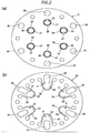
- a suction port 20 and a discharge port 30 corresponding to each cylinder bore 12 are formed in the valve plate 3. Furthermore, by an annular groove 28 being formed in a periphery of the suction port 20 of the valve plate 3, a valve seat 27 on which a suction valve 21 sits is formed in a circular form on a peripheral edge of an aperture of the suction port 20, and by an annular groove 38 being formed in a periphery of the discharge port 30 of the valve plate 3, a valve seat 37 on which a discharge valve 31 sits is formed in a circular form on a peripheral edge of an aperture of the discharge port 30.
- a suction chamber 18, which houses working fluid to be supplied to the compression chamber 17, and a discharge chamber 19, which houses working fluid that has been discharged from the compression chamber 17, are provided segregated in the cylinder head 4.
- the suction chamber 18 is formed in a central portion of the cylinder head 4, and the discharge chamber 19 is formed in an annular form in a periphery of the suction chamber 18.
- the suction chamber 18 can communicate with the compression chamber 17 via the suction port 20, which is opened and closed by the suction valve 21, to be described hereafter.
- the discharge chamber 19 can communicate with the compression chamber 17 via the discharge port 30, which is opened and closed by the discharge valve 31, to be described hereafter.
- a discharge valve sheet 32 which is superimposed on and attached to an end face on the cylinder head side of the valve plate 3 and in which the discharge valve 31 is formed
- a gasket 36 which is superimposed on the discharge valve sheet 32 and fixed by being gripped between the valve plate 3 and the cylinder head 4, in addition to which a retainer 35 is integrally formed in a region opposing the discharge valve 31, are provided between the valve plate 3 and the cylinder head 4.
- the cylinder block 2, the gasket 26, the suction valve sheet 22, the valve plate 3, the discharge valve sheet 32, the gasket 36, and the cylinder head 4 are positioned by unshown positioning pins, and fixed in a press-fit state by the fastening bolts that fasten the components of the housing 7.
- the suction chamber 18 communicates with an unshown suction aperture connected to a low pressure side (an evaporator exit side) of an external refrigerant circuit via a suction passage provided extending in a radial direction so as to penetrate the discharge chamber 19, and the discharge chamber 19 communicates with a discharge space 41 formed in a peripheral wall portion of the cylinder block 2 via a passage formed in the gasket 36, the valve plate 3, the suction valve sheet 22, the gasket 26, and the cylinder block 2.
- the discharge space 41 is defined by the cylinder block 2 and a cover 42 attached to the cylinder block 2, and is connected to a high pressure side (a condenser entrance side) of the external refrigerant circuit via a discharge aperture 43 formed in the cover 42.
- the suction valve sheet 22 is superimposed on and attached to the end face on the cylinder block side of the valve plate 3 shown in Fig. 2A , and is formed of an assembly of a multiple of the suction valve 21 that opens and closes the suction port 20, as shown in Fig. 2B , because of which the suction valves 21 are formed at predetermined intervals in a circumferential direction in the suction valve sheet 22 in accordance with the number of cylinder bores 12, and also, a through hole for inserting a fastening bolt through, a through hole for inserting an unshown positioning pin through, and the like, are formed. Also, an aperture portion 25 that avoids interference with the discharge port 30 is formed in a base end portion of each suction valve 21.
- Each suction valve 21 is configured of one portion of the suction valve sheet 22, and in the embodiment, a reed valve is used.
- the suction valve 21 has a region of a leading end of an arm portion 23 as a seat portion that sits on the valve seat 27 formed in a periphery of the suction port 20 of the valve plate 3. A more detailed structure of the suction valve 21 will be described hereafter.
- the gasket 26 interposed between the suction valve sheet 22 and the cylinder block 2 is such that aperture portions that avoid interference with the cylinder bore 12 are formed at predetermined intervals in a circumferential direction in accordance with the number of cylinder bores 12, and also, a through hole for inserting a fastening bolt through, a through hole for inserting a positioning pin through, and the like, are formed.
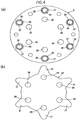
- the discharge valve sheet 32 is superimposed on and attached to the end face on the cylinder head side of the valve plate 3 shown in Fig. 4A , and is configured of an assembly of a multiple of the discharge valve 31 that opens and closes the discharge port 30, as shown in Fig. 4B .
- the discharge valves 31 are formed at predetermined intervals in a circumferential direction in accordance with the number of cylinder bores 12. Also, an aperture portion 39 that avoids interference with the suction port 20, an unshown through hole for inserting a positioning pin through, and the like, are formed in the discharge valve sheet 32.
- Each discharge valve 31 is configured of one portion of the discharge valve sheet 32, and in the embodiment, the discharge valve 31 is formed as a reed valve having an arm portion 33 extended radially in an outward direction, and has a region of a leading end of the arm portion 33 as a seat portion that sits on the valve seat 37 formed in a periphery of the discharge port 30 of the valve plate 3.
- the gasket 36 interposed between the discharge valve sheet 32 and the cylinder head 4 is such that aperture portions that avoid interference with the suction port 20 are formed at predetermined intervals in a circumferential direction in accordance with the number of cylinder bores, and also, a through hole for inserting a fastening bolt through, a through hole for inserting a positioning pin through, and the like, are formed, and the retainer 35 is formed integrally in a place opposing the discharge valve 31 so as to become gradually distanced progressing from a base side toward the leading end side of the arm portion 33 of the discharge valve 31.
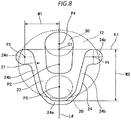
- suction valve 21 is configured to have the arm portion 23, wherein a tongue form is formed by an outer side form and an inner side form, as shown in particular in Fig. 6 to Fig. 8 .
- the outer side form of the arm portion 23 is formed by a U-form slit portion 24, formed of a leading end portion 24a, a pair of base portions 24c and 24c, and a pair of intermediate portions 24b and 24b between the leading end portion 24a and the base portion 24c, being provided in the suction valve sheet 22.
- the pair of intermediate portions 24b and 24b of the slit portion 24 are formed consistently with a width H1 of a lateral direction gap of, for example, 2mm, and furthermore, in the embodiment, the pair of intermediate portions 24b and 24b extend linearly.
- the leading end portion 24a of the slit portion 24 is formed consistently with a width H2 of a lateral direction gap of, for example, 1.6mm to 1.7mm. In a boundary region between the intermediate portion 24b and the leading end portion 24a, the width of one lateral direction gap gradually increases or decreases so as to become the width of the other gap.
- the pair of base portions 24c and 24c are formed in a circular form, whereby a width H3 of a gap passing through a central point P1 of a circular groove in the base portion 24c is greater than both the lateral direction gap widths H1 and H2 of the leading end portion 24a and the intermediate portion.
- the inner side form of the arm portion 23 is formed by the aperture portion 25, which is of a long hole form extending from a vicinity of a peripheral edge of the suction valve sheet 22 toward a central point P2 side of the cylinder bore 12, being provided between one intermediate portion 24b and base portion 24c of the slit portion 24 of the suction valve sheet 22 and the other intermediate portion 24b and base portion 24c.
- This kind of arm portion 23 of the suction valve 21 is such that a position of a width direction reference line L1 of the arm portion passing through ends of the pair of base portions 24c and 24c of the slit portion 24 on a side opposite to the direction in which the pair of intermediate portions 24b and 24b extend toward the leading end portion 24a forms a base of the suction valve 21, and an end on a side opposite to the base, with the central point P2 of the cylinder bore 12 in between, is a leading end.
- the central line L4 of the arm portion also passes through a central point P4 of the discharge port 30.
- the arm portion 23 of the suction valve 21 is such that a width on the base side is greater than a width on the leading end side. Furthermore, an angle of inclination R1 of the outer side reference line L2 from the central line L4 is greater than an angle of inclination R2 of the inner side reference line L3 from the central line L4 by a predetermined value or greater.
- the predetermined value of the difference between the angles of inclination is desirably 8 degrees or greater.
- the length direction dimension W2 is greater than the width direction dimension W1, but approximates the width direction dimension W1.
- the relationship between the width direction dimension W1 and the length direction dimension W2 of the arm portion 23 is desirably 1:1.8 or less.
- a position of a base of the arm portion 23 is farther to the discharge port 30 side than the central point P2 of the cylinder bore, but is in proximity to the central point P2 of the cylinder bore, that is, nearer to the central point P2 of the cylinder bore than in an existing suction valve.
- the outer side form and the inner side form of the arm portion 23 of the suction valve 21 are such that by setting the angle of inclination R1 of the outer side reference line L2 to be 8 degrees or more greater than the angle of inclination R2 of the inner side reference line L3, rigidity of the base of the arm portion 23 of the suction valve 21 can be increased, rendering the arm portion 23 less likely to warp, compared with when the width between the outer side form and the inner side form does not change between the base side and the leading end side, or when the difference between the angles of inclination R1 and R2 is smaller than 8 degrees even though the base side of the arm portion 23 is wider than the leading end side.
- the relationship between the length direction dimension W2 and the width direction dimension W1 of the arm portion 23 of the suction valve 21 is set to 1.8:1 or less, whereby the length direction dimension W2 of the arm portion 23 of the suction valve 21 is caused to be longer than but approximating the width direction dimension W1.
- the rigidity of the base of the arm portion 23 of the suction valve 21 can be increased, rendering the arm portion 23 less likely to warp, compared with when the relationship between the length direction dimension W2 and the width direction dimension W1 of the arm portion 23 is greater than 1.8:1.
- an opening and closing speed of the suction port 20 can be reduced even when a reed valve is used as the suction valve, and a speed at which the leading end of the arm portion 23 of the suction valve 21 comes into contact with the valve plate 3 or the valve seat 27, and by extension an impact, can be reduced. Furthermore, a secondary deformation after the leading end of the arm portion 23 of the suction valve 21 has come into contact with the valve seat 27 can be prevented. Because of this, damage such as cracking of the leading end of the arm portion 23 of the suction valve 21 is prevented, and reliability of the suction valve 21 can be ensured even when the reciprocating compressor 1 is operated at high speed.
Landscapes
- Engineering & Computer Science (AREA)
- Mechanical Engineering (AREA)
- General Engineering & Computer Science (AREA)
- Compressor (AREA)
- Check Valves (AREA)
- Compressors, Vaccum Pumps And Other Relevant Systems (AREA)
Applications Claiming Priority (1)
| Application Number | Priority Date | Filing Date | Title |
|---|---|---|---|
| JP2018115093A JP2019218879A (ja) | 2018-06-18 | 2018-06-18 | 往復動式圧縮機の吸入弁構造及び往復動式圧縮機 |
Publications (2)
| Publication Number | Publication Date |
|---|---|
| EP3584440A2 true EP3584440A2 (de) | 2019-12-25 |
| EP3584440A3 EP3584440A3 (de) | 2020-03-04 |
Family
ID=66867073
Family Applications (1)
| Application Number | Title | Priority Date | Filing Date |
|---|---|---|---|
| EP19180356.8A Withdrawn EP3584440A3 (de) | 2018-06-18 | 2019-06-14 | Saugventilanordnung für hubkolbenverdichter und hubkolbenverdichter |
Country Status (2)
| Country | Link |
|---|---|
| EP (1) | EP3584440A3 (de) |
| JP (1) | JP2019218879A (de) |
Families Citing this family (1)
| Publication number | Priority date | Publication date | Assignee | Title |
|---|---|---|---|---|
| CN113374672B (zh) * | 2021-07-12 | 2022-12-20 | 珠海格力节能环保制冷技术研究中心有限公司 | 阀片组件、压缩机以及具有其的冰箱 |
Citations (2)
| Publication number | Priority date | Publication date | Assignee | Title |
|---|---|---|---|---|
| US2587085A (en) | 1947-03-13 | 1952-02-26 | Philip C Anderson | Device for applying liquid fertilizer |
| JP2000054961A (ja) | 1998-06-05 | 2000-02-22 | Toyota Autom Loom Works Ltd | 圧縮機の吸入弁装置 |
Family Cites Families (3)
| Publication number | Priority date | Publication date | Assignee | Title |
|---|---|---|---|---|
| US4976284A (en) * | 1990-01-16 | 1990-12-11 | General Motors Corporation | Reed valve for piston machine |
| EP1936195A1 (de) * | 2005-09-07 | 2008-06-25 | Valeo Thermal Systems Japan Corporation | Hubkolbenverdichter |
| EP2865893B1 (de) * | 2013-09-23 | 2021-04-28 | Halla Visteon Climate Control Corp. | Ventilanordnung für Taumelscheibenkompressor mit variabler Verdrängung |
-
2018
- 2018-06-18 JP JP2018115093A patent/JP2019218879A/ja not_active Withdrawn
-
2019
- 2019-06-14 EP EP19180356.8A patent/EP3584440A3/de not_active Withdrawn
Patent Citations (2)
| Publication number | Priority date | Publication date | Assignee | Title |
|---|---|---|---|---|
| US2587085A (en) | 1947-03-13 | 1952-02-26 | Philip C Anderson | Device for applying liquid fertilizer |
| JP2000054961A (ja) | 1998-06-05 | 2000-02-22 | Toyota Autom Loom Works Ltd | 圧縮機の吸入弁装置 |
Also Published As
| Publication number | Publication date |
|---|---|
| JP2019218879A (ja) | 2019-12-26 |
| EP3584440A3 (de) | 2020-03-04 |
Similar Documents
| Publication | Publication Date | Title |
|---|---|---|
| US5632609A (en) | Valved discharge mechanism of a refrigerant compressor | |
| US20070253837A1 (en) | Variable capacity swash plate type compressor | |
| US10316831B2 (en) | Valve assembly for variable swash plate compressor | |
| US7632077B2 (en) | Inclined plate-type compressors and air conditioning systems including such compressors | |
| CN101072945B (zh) | 压缩机 | |
| EP3584440A2 (de) | Saugventilanordnung für hubkolbenverdichter und hubkolbenverdichter | |
| CN110073105B (zh) | 压缩机的阀构造 | |
| US20020146328A1 (en) | Compressor provided with pressure relief valve | |
| KR100508834B1 (ko) | 밀폐형 압축기 | |
| KR20090083194A (ko) | 압축기 | |
| WO2018062479A1 (ja) | 圧縮機の弁構造 | |
| KR20160034119A (ko) | 압축기의 토출밸브 조립체 | |
| KR20150060199A (ko) | 왕복식 압축기 | |
| KR20110098215A (ko) | 용량가변형 압축기의 체크밸브 | |
| JPH062654A (ja) | 圧縮機 | |
| KR20130092880A (ko) | 가변용량형 사판식 압축기의 밸브어셈블리 | |
| KR101177294B1 (ko) | 가변용량형 사판식 압축기 | |
| JPH02161182A (ja) | 圧縮機の吸入弁機構 | |
| KR101613986B1 (ko) | 압축기의 밸브플레이트 조립체 | |
| KR102734369B1 (ko) | 흡입 체크밸브 및 이를 포함하는 압축기 | |
| KR101984510B1 (ko) | 압축기 | |
| KR20220017766A (ko) | 압축기 | |
| KR102073108B1 (ko) | 가변 사판식 압축기용 흡입체크밸브 및 이의 조립방법 | |
| KR101998276B1 (ko) | 압축기용 밸브 유니트 | |
| KR20170035254A (ko) | 가변 용량형 사판식 압축기 |
Legal Events
| Date | Code | Title | Description |
|---|---|---|---|
| PUAI | Public reference made under article 153(3) epc to a published international application that has entered the european phase |
Free format text: ORIGINAL CODE: 0009012 |
|
| STAA | Information on the status of an ep patent application or granted ep patent |
Free format text: STATUS: THE APPLICATION HAS BEEN PUBLISHED |
|
| AK | Designated contracting states |
Kind code of ref document: A2 Designated state(s): AL AT BE BG CH CY CZ DE DK EE ES FI FR GB GR HR HU IE IS IT LI LT LU LV MC MK MT NL NO PL PT RO RS SE SI SK SM TR |
|
| AX | Request for extension of the european patent |
Extension state: BA ME |
|
| PUAL | Search report despatched |
Free format text: ORIGINAL CODE: 0009013 |
|
| AK | Designated contracting states |
Kind code of ref document: A3 Designated state(s): AL AT BE BG CH CY CZ DE DK EE ES FI FR GB GR HR HU IE IS IT LI LT LU LV MC MK MT NL NO PL PT RO RS SE SI SK SM TR |
|
| AX | Request for extension of the european patent |
Extension state: BA ME |
|
| RIC1 | Information provided on ipc code assigned before grant |
Ipc: F04B 39/10 20060101ALI20200128BHEP Ipc: F04B 27/08 20060101AFI20200128BHEP |
|
| STAA | Information on the status of an ep patent application or granted ep patent |
Free format text: STATUS: REQUEST FOR EXAMINATION WAS MADE |
|
| 17P | Request for examination filed |
Effective date: 20200831 |
|
| RBV | Designated contracting states (corrected) |
Designated state(s): AL AT BE BG CH CY CZ DE DK EE ES FI FR GB GR HR HU IE IS IT LI LT LU LV MC MK MT NL NO PL PT RO RS SE SI SK SM TR |
|
| STAA | Information on the status of an ep patent application or granted ep patent |
Free format text: STATUS: EXAMINATION IS IN PROGRESS |
|
| 17Q | First examination report despatched |
Effective date: 20210305 |
|
| STAA | Information on the status of an ep patent application or granted ep patent |
Free format text: STATUS: THE APPLICATION IS DEEMED TO BE WITHDRAWN |
|
| 18D | Application deemed to be withdrawn |
Effective date: 20210716 |