EP3584151B1 - Modulare unterbodenanordnung für ein flugzeug - Google Patents
Modulare unterbodenanordnung für ein flugzeug Download PDFInfo
- Publication number
- EP3584151B1 EP3584151B1 EP18400017.2A EP18400017A EP3584151B1 EP 3584151 B1 EP3584151 B1 EP 3584151B1 EP 18400017 A EP18400017 A EP 18400017A EP 3584151 B1 EP3584151 B1 EP 3584151B1
- Authority
- EP
- European Patent Office
- Prior art keywords
- modular
- structural frames
- tank
- fuselage
- helicopter
- Prior art date
- Legal status (The legal status is an assumption and is not a legal conclusion. Google has not performed a legal analysis and makes no representation as to the accuracy of the status listed.)
- Active
Links
Images

Classifications
-
- B—PERFORMING OPERATIONS; TRANSPORTING
- B64—AIRCRAFT; AVIATION; COSMONAUTICS
- B64D—EQUIPMENT FOR FITTING IN OR TO AIRCRAFT; FLIGHT SUITS; PARACHUTES; ARRANGEMENT OR MOUNTING OF POWER PLANTS OR PROPULSION TRANSMISSIONS IN AIRCRAFT
- B64D37/00—Arrangements in connection with fuel supply for power plant
- B64D37/02—Tanks
- B64D37/04—Arrangement thereof in or on aircraft
-
- B—PERFORMING OPERATIONS; TRANSPORTING
- B64—AIRCRAFT; AVIATION; COSMONAUTICS
- B64C—AEROPLANES; HELICOPTERS
- B64C1/00—Fuselages; Constructional features common to fuselages, wings, stabilising surfaces or the like
- B64C1/06—Frames; Stringers; Longerons ; Fuselage sections
- B64C1/061—Frames
-
- B—PERFORMING OPERATIONS; TRANSPORTING
- B64—AIRCRAFT; AVIATION; COSMONAUTICS
- B64C—AEROPLANES; HELICOPTERS
- B64C1/00—Fuselages; Constructional features common to fuselages, wings, stabilising surfaces or the like
- B64C1/18—Floors
-
- B—PERFORMING OPERATIONS; TRANSPORTING
- B64—AIRCRAFT; AVIATION; COSMONAUTICS
- B64C—AEROPLANES; HELICOPTERS
- B64C27/00—Rotorcraft; Rotors peculiar thereto
-
- B—PERFORMING OPERATIONS; TRANSPORTING
- B64—AIRCRAFT; AVIATION; COSMONAUTICS
- B64D—EQUIPMENT FOR FITTING IN OR TO AIRCRAFT; FLIGHT SUITS; PARACHUTES; ARRANGEMENT OR MOUNTING OF POWER PLANTS OR PROPULSION TRANSMISSIONS IN AIRCRAFT
- B64D37/00—Arrangements in connection with fuel supply for power plant
- B64D37/02—Tanks
- B64D37/06—Constructional adaptations thereof
-
- B—PERFORMING OPERATIONS; TRANSPORTING
- B64—AIRCRAFT; AVIATION; COSMONAUTICS
- B64D—EQUIPMENT FOR FITTING IN OR TO AIRCRAFT; FLIGHT SUITS; PARACHUTES; ARRANGEMENT OR MOUNTING OF POWER PLANTS OR PROPULSION TRANSMISSIONS IN AIRCRAFT
- B64D37/00—Arrangements in connection with fuel supply for power plant
- B64D37/02—Tanks
- B64D37/14—Filling or emptying
- B64D37/16—Filling systems
-
- B—PERFORMING OPERATIONS; TRANSPORTING
- B64—AIRCRAFT; AVIATION; COSMONAUTICS
- B64F—GROUND OR AIRCRAFT-CARRIER-DECK INSTALLATIONS SPECIALLY ADAPTED FOR USE IN CONNECTION WITH AIRCRAFT; DESIGNING, MANUFACTURING, ASSEMBLING, CLEANING, MAINTAINING OR REPAIRING AIRCRAFT, NOT OTHERWISE PROVIDED FOR; HANDLING, TRANSPORTING, TESTING OR INSPECTING AIRCRAFT COMPONENTS, NOT OTHERWISE PROVIDED FOR
- B64F5/00—Designing, manufacturing, assembling, cleaning, maintaining or repairing aircraft, not otherwise provided for; Handling, transporting, testing or inspecting aircraft components, not otherwise provided for
- B64F5/10—Manufacturing or assembling aircraft, e.g. jigs therefor
-
- B—PERFORMING OPERATIONS; TRANSPORTING
- B64—AIRCRAFT; AVIATION; COSMONAUTICS
- B64F—GROUND OR AIRCRAFT-CARRIER-DECK INSTALLATIONS SPECIALLY ADAPTED FOR USE IN CONNECTION WITH AIRCRAFT; DESIGNING, MANUFACTURING, ASSEMBLING, CLEANING, MAINTAINING OR REPAIRING AIRCRAFT, NOT OTHERWISE PROVIDED FOR; HANDLING, TRANSPORTING, TESTING OR INSPECTING AIRCRAFT COMPONENTS, NOT OTHERWISE PROVIDED FOR
- B64F5/00—Designing, manufacturing, assembling, cleaning, maintaining or repairing aircraft, not otherwise provided for; Handling, transporting, testing or inspecting aircraft components, not otherwise provided for
- B64F5/60—Testing or inspecting aircraft components or systems
-
- B—PERFORMING OPERATIONS; TRANSPORTING
- B64—AIRCRAFT; AVIATION; COSMONAUTICS
- B64C—AEROPLANES; HELICOPTERS
- B64C2211/00—Modular constructions of airplanes or helicopters
-
- B—PERFORMING OPERATIONS; TRANSPORTING
- B64—AIRCRAFT; AVIATION; COSMONAUTICS
- B64C—AEROPLANES; HELICOPTERS
- B64C27/00—Rotorcraft; Rotors peculiar thereto
- B64C27/04—Helicopters
Definitions
- the invention is related to a helicopter with a modular subfloor with a modular tank system.
- continuous frames and/or longerons cover the entire cross section of a subfloor region of a rotary wing aircraft below the floor panel and divide the subfloor region into several individual compartments.
- a fuel tank system that is usually located in such a subfloor region is thereby required to be separated into several individual fuel bladders which have to be interconnected to each other by means of special fuel system devices such as transfer pipes for fuel transfer between two adjacent fuel bladders and scavenge lines for fuel transfer from e.g. main tanks to feeder tanks.
- These special fuel system devices have to be conducted through these structural elements, i.e. the frames and/or longerons, and these frames and/or longerons have to be provided with suitable cut-outs. Since integration of the fuel bladders is accomplished after the structural airframe assembly, considerable integration efforts need to be made in terms of installing the fuel systems and connecting the corresponding fuel bladders.
- the fuel tank integration procedure is often complex. After the structural assembly, the floor panel has to be removed, the individual fuel bladders are mounted within the subfloor structure, connected to each other, and subsequently the floor panel has to be reinstalled. Special care has to be taken for a leakage-free installation of the fuel transfer lines.
- Document US 9,623,950 B2 describes a fuel tank and a differential frame in a fuselage airframe of a helicopter, the fuel tank being installed between the fuselage lower cover shell and the floor panel.
- the differential frame separates the fuel tank into two individual compartments, the differential frame having a web below the floor panel with a variable-height with a minimum height at the symmetry axis of the fuselage cross-section and a maximum height at lateral frame roots regions.
- a transversal beam is attached at each of its both ends to the differential frame bridging the entire variable-height of the differential frame and the fuel tank with two front and rear fuel bladders covering both individual tank compartments with a middle bladder installed between the transversal beam and the variable-height web of the differential frame.
- Document US 9,688,381 B2 describes a subfloor structure with an integral hull, for a rotary wing aircraft.
- the subfloor structure comprises an integral subfloor hull that defines in one piece, upward web portions acting as longerons and a bottom central portion offering both load bearing capabilities and aerodynamical loft features.
- the subfloor structure is adapted to accommodate fuel tanks and is useful for rotary wing aircrafts such as helicopters and is e.g. made of composite and/or light alloy such as aluminium.
- Document US 9,517,831 B2 describes a rotary wing aircraft airframe with a longitudinal axis comprising: a subfloor structure for supporting cabin floor panels and/or at least one fuel tank bladder.
- Said subfloor structure has a bottom shell, longitudinal support beams, ribs, main frames and floor panels.
- the bottom shell has a flat shell portion and two lateral shell portions extending integrally from said flat shell portion along its longitudinally oriented sides and being curved towards respective front edges of said ribs and main frames.
- the longitudinal support beams are provided with attachments for the floor panels, the longitudinal support beams are attached at least partially to the ribs and/or the main frames and the longitudinal support beams are featuring along at least 2/3 of their longitudinal extension a height 2 to 20 times smaller than any distances of any of the floor panels to the bottom shell.
- Document US 9,868,544 B2 describes a rotorcraft having a feed unit for feeding fuel to a power plant of the rotorcraft.
- a middle floor is securely engaged with at least two frames of the fuselage and being load-bearing relative to general forces supported by the fuselage.
- a bottom compartment of the rotorcraft does not have the load-bearing covering of the fuselage, the bottom face of the fuselage being open to the outside by providing the bottom compartment with a bottom open to the outside of the rotorcraft.
- the bottom face of the middle floor forms an anchor member for suspending of at least one fuel tank that is accessible from outside the fuselage via said open bottom.
- Document WO 2015/048695 A1 describes an aircraft auxiliary fuel tank system that comprises a master tank and a plurality of slave tanks connectable to the master tank.
- the slave tanks can be easily added or removed to adjust fuel capacity.
- a rail assembly is provided to assist in the easy installation and removal of the slave and master fuel tanks. Methods are provided for using the auxiliary fuel tanks system and for providing a service for slave tank distribution, reservation and installation.
- none of these documents describes a modular subfloor system with a modular tank system. More particularly, none of these documents describes a modular subfloor system with a modular tank system that can be assembled, tested with respect to fuel volume, tightness, pressure, as well as quality checked independent of remaining fuselage parts of an aircraft, i.e. before the assembly of the modular subfloor system with the remaining fuselage parts of the aircraft.
- the fuel system is sealed and closed and has to be checked by a pressure test.
- leakages occur, resealing tasks have to be realized.
- defect detection procedures may be very time consuming as they often require large disassembly and reassembly efforts for defect remedy. The same applies for maintenance operations of the fuel tank in conventional aircrafts.
- an objective is to provide an aircraft, in particular a helicopter, with a modular subfloor system that allows being assembled and tested independently of the remaining portions of the aircraft.
- a modular tank system should simplify the modular subfloor system assembly procedure as well as the integration of the modular subfloor system with the remaining portions of the aircraft.
- a helicopter with a fuselage system comprises a modular subfloor system which is one of several components of the fuselage system, the modular subfloor system being a pre-equipped component that is equipped separately and independently from any other component of the several components of the fuselage system in a separate workflow prior to assembling the modular subfloor system with other components of the fuselage system.
- the modular subfloor system comprises first longitudinal structural frames, lateral regions, and a modular tank system that is configured to be assembled, sealed, tested, and quality checked prior to assembling the modular subfloor system with the other components of the fuselage system, wherein the modular tank system is connected to the first longitudinal structural frames.
- the modular tank system comprises a bottom shell of the helicopter, an upper panel, second longitudinal structural frames that are arranged between the bottom shell and the upper panel, transversal structural frames that are arranged between the bottom shell and the upper panel, wherein the transversal structural frames and the second longitudinal structural frames form compartments, tank bladders that are arranged in at least some of the compartments, and sealing elements that seal the upper panel, the bottom shell, and the at least some of the compartments of the modular tank system to ensure at least tightness of the modular tank system relative to the lateral regions.
- the modular subfloor system and the rest of the aircraft may be equipped in parallel by independent and separate work flows.
- a first team may build the structural fuselage element in which the tank system is installed in form of a pre-equipped airframe-tank system unit, and, at the same time, a second team may build another airframe/fuselage element.
- the pre-equipped airframe-tank system may include structural parts, fuel transfer and feeding lines, sealing elements, at least portions of a cabin floor, tank bladders, and refuelling ports.
- the modular tank system may be assembled, sealed, tested, and quality checked independent from the rest of the aircraft, which enables parallel production workflows as well as ergonomic working conditions and results in an increasing quality and decreasing recurring costs.
- working in parallel on the modular subfloor system and the rest of the aircraft may reduce manufacturing costs and processing time.
- the modular tank system may improve ergonomic conditions for tank bladder installation, pipe installation, etc.
- working separately on the remaining parts of the aircraft may improve ergonomic conditions for installation tasks including installing the wiring harness, the fuel lines, the ventilation lines, the ducting for air-condition systems, the ducting for heating systems, etc.
- the modular tank system may be checked for quality and leakage before being assembled with the remaining portions of the aircraft. Thereby, potential problems with the modular tank system can be dealt with before the assembly with the remaining portions of the aircraft and intensive re-work on a complete aircraft can be avoided.
- the upper panel forms at least a portion of a cabin floor surface of the helicopter.
- the modular subfloor system comprises additional transversal structural frames that connect the first longitudinal structural frames.
- the modular subfloor system comprises an additional bottom shell that is connected to the first longitudinal structural frames and the additional transversal structural frames.
- At least one structural component of the first longitudinal structural frames, the second longitudinal structural frames, the transversal structural frames, or the additional transversal structural frames is adapted for receiving an upper fuselage.
- the upper fuselage comprises vertical structural frames that are attached to the at least one structural component.
- the modular subfloor system comprises attachment points that are adapted for receiving a canopy frame.
- the modular tank system comprises pipes that connect at least a portion of the tank bladders for fuel transfer between the tank bladders, and refuelling ports that provide access to the tank bladders from outside the modular tank system for filling the tank bladders with fuel.
- the modular tank system further comprises equipment plates that are arranged on the bottom shell of the modular tank system.
- the equipment plates provide access to the tank bladders from outside the modular tank system for quality testing of the modular tank system.
- a method for assembly of a helicopter with a fuselage system that comprises a modular subfloor system, wherein the modular subfloor system is one of several components of the fuselage system, and wherein the modular subfloor system is a pre-equipped component that is equipped separately and independently from any other component of the several components of the fuselage system in a separate workflow prior to assembling the modular subfloor system with other components of the fuselage system, comprises: receiving first and second longitudinal structural frames, connecting transversal structural frames with the second longitudinal structural frames, attaching a bottom shell to the transversal structural frames and second longitudinal structural frames to form compartments, arranging tank bladders in at least some of the compartments, attaching an upper panel to the transversal structural frames and second longitudinal structural frames, sealing the upper panel and the bottom shell to form a modular tank system, and connecting the modular tank system with the first longitudinal structural frames to form the modular subfloor system.
- the modular subfloor system is assembled with the other components of the fuselage system.
- arranging the tank bladders in at least some of the compartments further comprises performing quality tests of the tank bladders within the compartments, wherein the quality tests comprise at least a leak test of the modular tank system.
- Exemplary embodiments may be included in any vehicles with a subfloor system that may include a tank system, if desired.
- vehicles may include aircrafts such as airplanes, multicopters, helicopters, drones, or other vehicles that are fuel-driven such as cars, buses, trucks, ships, etc.
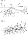
- Figure 1 shows an example of a vehicle 1.
- the vehicle 1 may be an aircraft and, more particularly, a rotary wing aircraft 1.
- Rotary wing aircraft 1 is exemplarily illustrated as a helicopter.
- helicopter 1 rotary wing aircraft 1 is hereinafter referred to as "helicopter 1".
- a first direction X is referred to as “longitudinal direction” or “longitudinal axis”.
- a rotation around the longitudinal axis of an aircraft is called “roll”. Terms such as front or rear of the aircraft are relative thereto.
- a second direction Y is referred to as "transverse direction” or “transverse axis”.
- transverse direction or "transverse axis”.
- pitch a rotation around the transverse axis of an aircraft.
- side, “left”, or “right” of the aircraft are relative thereto.
- a third direction Z is referred to as "vertical direction”, “vertical axis”, “elevation”, or “elevation axis”.
- a rotation around the elevation axis of an aircraft is called “yaw”. Terms such as “up”, “down”, “high”, or “low” are relative thereto.
- the directions X, Y and Z together define a referential "XYZ” axis.
- the directions X and Z together define ante posterior plane XZ of rotary wing aircraft 1.
- Helicopter 1 may include one or more rotors, fuselage system 2, modular subfloor system 3, and landing gear 3A. As shown in Figure 1 , the one or more rotors may include main rotor 1A and tail rotor 1B. Fuselage system 2 may extend longitudinally and laterally aside ante posterior plane XZ of helicopter 1. If desired, fuselage system 2 may include modular subfloor system 3 that is illustratively connected to landing gear 3A. Landing gear 3A is exemplarily embodied as a wheel landing gear. If desired, modular subfloor system 3 may include modular tank system 5 that may be arranged under cabin floor surface 4. Cabin floor surface 4 may include a portion of the cabin floor. Helicopter 1 may also have additional equipment.
- Main rotor 1A of helicopter 1 may be illustratively implemented as a multi-blade rotor. Rotor blades are mounted at an associated rotor head, rotate during operation of helicopter 1 around elevation axis Z, and provide lift and forward or backward thrust.
- Figure 2 shows illustrative modular subfloor system 3 that may include modular tank system 5, attachment points 18, lateral regions 14, and structural components 15 that are adapted for receiving a part of a fuselage system such as an upper part of fuselage system 2 of Figure 1 .
- Modular tank system 5 may be connected to longitudinal structural frames 6.
- modular tank system 5 may be at least partially surrounded by lateral regions 14.
- Modular tank system 5 may include bottom shell 8, upper panel 9, and longitudinal structural frames 7 and transversal structural frames 10 that are arranged between bottom shell 8 and upper panel 9.
- transversal structural frames 10 and longitudinal structural frames may be attached to at least one of bottom shell 8 or upper panel 9.
- upper panel 9 may form at least a portion of cabin floor surface 4.
- Transversal structural frames 10 and longitudinal structural frames 7 may form compartments 11. If desired, tank bladders 12 may be arranged in at least some of the compartments formed by transversal structural frames 10 and longitudinal structural frames 7. Sealing elements may seal upper panel 9, bottom shell 8, and the at least some of the compartments 11 of the modular tank system 5 to ensure at least tightness of the modular tank system 5 relative to the lateral regions.
- modular tank system 5 may be separated from bottom shell 8 of the rotary wing aircraft, for example by auxiliary compartments.
- modular tank system 5 and bottom shell 8 may be separate parts of modular subfloor system 3.
- bottom shell 8 may be a convex-shaped bowl part.
- bottom shell 8 may include a sandwich design with monolithic regions all along longitudinal structural frames 6.
- longitudinal structural frames 6 may be arranged parallel to ante posterior plane XZ. As an example, longitudinal structural frames 6 may span the entire length of modular subfloor system 3. If desired, in such modular subfloor system 3, transversal structural frames 10 may form crossbeams. In other words, transversal structural frames 10 may be arranged orthogonally to ante posterior plane XZ. If desired, transversal structural frames 10 may span the whole width of modular subfloor system 3.
- modular subfloor system 3 may house various systems and/or pieces of equipment (e.g., electrical, mechanical, or armouring equipment) such as tank bladders 12, pipes 20, sealing elements, refuelling ports 21, test lines, fuel transfer lines, fuel feeding lines, structural components 15, wiring harness, ducting for air-condition systems, and ducting for heating systems, etc.
- equipment e.g., electrical, mechanical, or armouring equipment
- tank bladders 12 pipes 20, sealing elements, refuelling ports 21, test lines, fuel transfer lines, fuel feeding lines, structural components 15, wiring harness, ducting for air-condition systems, and ducting for heating systems, etc.
- these systems and/or pieces of equipment may be arranged in lateral regions 14 and/or in modular tank system 5.
- lateral regions 14 may be located laterally between longitudinal structural frames 6 and outside portions of modular subfloor system 3.
- modular subfloor system 3 may provide for substantial kinetic energy absorption in a crash scenario of helicopter 1.
- Longitudinal structural frames 6 may be beams that work as main load carrying members.
- structural components 15 for receiving a part of a fuselage system such as a part of fuselage system 2 of Figure 1 may be arranged on longitudinal structural frames 6, longitudinal structural frames 7, and/or transversal structural frames 10.
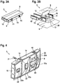
- Figure 3A shows an illustrative modular tank system 5 that includes bottom shell 8, upper panel 9, longitudinal structural frames, and transversal structural frames 10.
- longitudinal structural frames e.g., longitudinal structural frames 7 of Figure 3B
- transversal structural frames 10 may be arranged between bottom shell 8 and upper panel 9 and form compartments.
- tank bladders may be installed in at least some of the compartments formed by longitudinal structural frames and transversal structural frames 10.
- lateral regions 14 which may be adjacent to modular tank system 5. If desired, some portions of modular tank system 5 may be arranged in lateral regions 14. Sealing elements may seal upper panel 9, bottom shell 8, and the at least some of the compartments 11 of the modular tank system 5 to ensure at least tightness of the modular tank system 5 relative to lateral regions 14.
- lateral regions 14 may include refuelling ports 21 for refuelling tank bladders and at least one structural component 15 for receiving a part of a fuselage system such as a part of fuselage system 2 of Figure 1 .
- Upper panel 9 may form at least a portion of cabin floor surface 4 of modular subfloor system 3.
- FIG. 3B shows an exploded view of illustrative modular tank system 5.
- modular tank system 5 may include longitudinal structural frame 7 and transversal structural frames 10 that are arranged between bottom shell 8 and upper panel 9. If desired, at least one of bottom shell 8 or upper panel 9 may be attached to transversal structural frames 10 and/or longitudinal structural frames 7.
- Transversal structural frames 10 and longitudinal structural frames 7 may form compartments 11 between bottom shell 8 and upper panel 9.
- tank bladders 12 may be installed. Tank bladders 12 may be connected with each other using pipes 20, if desired.
- modular tank system 5 may include sealing elements that seal upper panel 9, bottom shell 8, and compartments 11 of modular tank system 5 to ensure tightness of modular tank system 5.
- Upper panel 9 may form at least a portion of cabin floor surface 4 of modular subfloor system 3.
- a modular subfloor system such as modular subfloor system 3 of Figure 2 may include modular tank system 5 of Figures 3A or 3B .
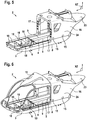
- Figure 4 shows an illustrated bottom view of modular tank system 5 that includes bottom shell 8, equipment plates 22 for covering equipment holes 22a that are arranged on bottom shell 8, transversal structural frame 10 that is attached to bottom shell 8, refuelling port 21, and structural elements 15 that are arranged on lateral region 14 of modular tank system 5.
- Equipment plates that are arranged on bottom shell 8 may cover equipment holes 22a that provide access to tank bladders 12, pipes, hoses, fittings, ports, etc. and/or other equipment within modular tank system 5 such as ventilation and filler lines from outside modular tank system 5. Such access may be desirable for the maintenance and/or the installation of modular tank system 5.
- such modular tank system 5 may include refuelling ports 21 for refuelling tank bladders and structural components 15 for receiving a part of a fuselage system. If desired, refuelling ports 21 and structural components 15 may be arranged in lateral regions 14. If desired, structural components 15 may also be arranged on longitudinal structural frames and/or transversal structural frames 10 for receiving a part of a fuselage system.
- bottom shell 8 may be a single bowl-shaped part that may include a sandwich design with monolithic regions.
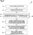
- Figure 5 shows illustrative parts of fuselage system 2 with upper fuselage 16 that is attached to modular subfloor system 3.
- Upper fuselage 16 may include side shells 24, vertical structural frames 17 that are arranged on side shells 24, and rear deck 23 that is attached to side shells 24.
- Modular subfloor system 3 may include attachment points 18 that are adapted for receiving upper fuselage 16, cabin floor surface 4, structural components 15, transversal structural frames 10, and modular tank system 5 that is arranged between longitudinal structural frames 6.
- Modular tank system 5 may include bottom shell 8, upper panel 9, and transversal structural frames 10 that are arranged between bottom shell 8 and upper panel 9.
- upper fuselage 16 may form a part of the cabin of a helicopter such as helicopter 1 of Figure 1 .
- upper fuselage 16 may form the rear part of the cabin.
- upper fuselage 16 may include storage for in-flight service, seats, and flight instruments. If desired, storage for in-flight service may be arranged in rear deck 23 of upper fuselage 16. Exemplary seats and flight instruments may be arranged in the space between side shells 24.
- vertical structural frames 17 may be arranged along ante posterior plane XZ. Vertical structural frames 17 and may span the entire height of side shells 24. If desired, vertical structural frames 17 may be attached to structural components 15 that are arranged on longitudinal structural frames 6.
- modular subfloor system 3 may house various systems and/or pieces of equipment (e. g. electrical, mechanical, and armouring equipment). Such systems and/or pieces of equipment may be arranged in lateral volumes that are enclosed between longitudinal structural frames 6 and side portions of bottom shell 8. If desired, modular subfloor system 3 may provide for substantial kinetic energy absorption in a crash scenario of a helicopter. Longitudinal structural frames 6 may be beams that work as main load carrying members.
- modular tank system 5 may include sealing elements that close and seal modular tank system 5.
- upper panel 9 may form at least a portion of cabin floor surface 4.
- Figure 6 shows illustrative fuselage system 2 that includes upper fuselage 16, canopy frame 19, and modular subfloor system 3.
- Upper fuselage 16 may include side shells 24, vertical structural frames 17 that are arranged on side shells 24, and rear deck 23 that is attached to side shells 24.
- Modular subfloor system 3 may include attachment points 18 that are adapted for receiving upper fuselage 16, cabin floor surface 4, structural components 15, transversal structural frames 10, and modular tank system 5 that is arranged between longitudinal structural frames 6.
- Modular tank system 5 may include bottom shell 8, upper panel 9, and transversal structural frames 10 that are arranged between bottom shell 8 and upper panel 9.
- Canopy frame 19 may be attached to vertical structural frames 17 of upper fuselage 16. If desired, canopy frame 19 may house various pieces of equipment such as flight instruments on an instrument panel or the controls that enable the pilot to fly the aircraft.
- Canopy frame 19 may be attached to modular subfloor system 3 at attachment points 18 that are arranged between longitudinal structural frames 6 and side portions of bottom shell 8. If desired, canopy frame 19 may be connected with modular subfloor system 3 using structural elements 15 that are arranged on longitudinal structural frames 6. In some embodiments, canopy frame 19 may form a cockpit of a helicopter such as helicopter 1 of Figure 1 . If desired, a door frame may be used between upper fuselage 16 and canopy frame 19 for separating the cockpit from the cabin.
- upper fuselage 16 may form a part of the cabin of a helicopter such as for example a rear part of the cabin.
- Upper fuselage 16 may include storage for in-flight service, seats, and flight instruments. If desired, storage for in-flight service may be arranged on rear deck 23 of upper fuselage 16. Exemplary seats and flight instruments may be arranged in the space between side shells 24.
- vertical structural frames 17 may be arranged along ante posterior plane XZ and may span the entire height of side shells 24. Vertical structural frames 17 may be attached with their bottom section to structural components 15 that are arranged on longitudinal structural frames 6.
- modular tank system 5 may include sealing elements that close and seal modular tank system 5.
- upper panel 9 may form at least a portion of cabin floor surface 4.
- modular subfloor system 3 may include modular tank system 5, which may be pre-checked for leakage and quality checked prior to assembling modular subfloor system 3 with the other components of fuselage system 2.
- Figure 7 is a flowchart 30 showing illustrative operations for assembling a modular subfloor system for an aircraft, such as modular subfloor system 3 of any of Figures 1 to 6 . If desired, an operator and/or one or more assembly lines may perform operations 31 to 38 of flowchart 30.
- the operator and/or the one or more assembly lines may receive first and second longitudinal structural frames.
- an assembly line may receive longitudinal structural frames 6 and longitudinal structural frames 7 of Figure 2 .
- the operator and/or the one or more assembly lines may connect transversal structural frames with second longitudinal structural frames.
- longitudinal structural frames 7 of Figure 2 may be connected with transversal structural frames 10.
- the operator and/or the one or more assembly lines may attach a bottom shell to the transversal and second longitudinal structural frames to form compartments.
- longitudinal structural frames 7 and transversal structural frames 10 may be attached to bottom shell 8 to form compartments 11.
- the operator and/or the one or more assembly lines may arrange tank bladders in at least some of the compartments.
- tank bladders 12 of Figure 2 may be arranged in at least some compartments 11.
- other parts of the fuel distribution system such as pipes, hoses, fittings, ports, etc. may be arranged in at least some compartments 11.
- the operator and/or the one or more assembly lines may perform quality tests of the tank bladders within the compartments.
- quality tests of tank bladders 12 of Figure 2 may be performed within compartments 11.
- the quality tests may include a leak test of modular tank system 5.
- the operator and/or the one or more assembly lines may attach an upper panel to the transversal and second longitudinal structural frames.
- longitudinal structural frames 7 and transversal structural frames 10 may be attached to upper panel 9.
- the operator and/or the one or more assembly lines may seal the upper panel and the bottom shell to form a modular tank system.
- upper panel 9 and bottom shell 8 may be sealed to form modular tank system 5.
- the operator and/or the one or more assembly lines may connect the modular tank system with the first longitudinal structural frames to form the modular subfloor system.
- modular tank system 5 may be connected with longitudinal structural frames 6 to form modular subfloor system 3.
- Figure 8 is a flowchart 40 showing illustrative operations for assembling a modular fuselage system for an aircraft such as assembling fuselage system 2 for rotary wing aircraft 1 of Figure 6 . If desired, an operator and/or one or more assembly lines may perform operations 41 to 48 of flowchart 40.
- the operator and/or one or more assembly lines may receive a modular tank system.
- a modular tank system For example, modular tank system 5 of Figure 6 may be received.
- the operator and/or one or more assembly lines may receive an upper fuselage.
- upper fuselage 16 of Figure 6 may be received.
- the operator and/or one or more assembly lines may perform quality tests of the modular tank system. For example, quality tests of modular tank system 5 of Figure 6 may be performed.
- the operator and/or one or more assembly lines may perform quality tests of the upper fuselage. For example, quality tests of upper fuselage 16 of Figure 6 may be performed.
- the operator and/or one or more assembly lines may perform operations 47 and 48 that are part of operation 43 in parallel.
- the operator and/or one or more assembly lines may connect the modular tank system with longitudinal structural frames to form a modular subfloor system.
- modular tank system 5 of Figure 6 may be connected with longitudinal structural frames 6 to form modular subfloor system 3.
- the operator and/or one or more assembly lines may mount the modular subfloor system to the upper fuselage by connecting at least one structural component.
- modular subfloor system 3 of Figure 6 may be mounted to upper fuselage 16 by connecting structural components 15 with upper fuselage 16.
- the operator and/or one or more assembly lines may mount a canopy frame to the upper fuselage and the modular subfloor system.
- canopy frame 19 of Figure 6 may be mounted to upper fuselage 16 and modular subfloor system 3.
- modular tank system 5 of Figure 3B is shown to include longitudinal structural frame 7, bottom shell 8, four transversal structural frames 10, upper panel 9, and two compartments 11.
- modular tank system 5 of Figure 3B may have any number of longitudinal and transversal structural frames 7, 10, and any number of compartments 11 that are formed by these longitudinal and transversal structural frames 7, 10.
- modular tank system 5 of Figure 4 is shown with four equipment plates 22 covering eight equipment holes 22a.
- modular tank system 5 of Figure 4 may have any number of equipment plates 22 with any number of equipment holes 22a.
- operations 41, 42, 47, 48, and 44 of Figure 8 are shown in a given order. However, operations 41, 47, and 44 are independent of operations 42 and 48. Thus, as long as operation 41 occurs before operation 47, operation 47 before operation 44, and operation 42 before 48, any order may be appropriate. For example, operations 42 and 48 may be performed in parallel with operations 41,47, and 44. As another example, the operations may be performed in the order 42, 41, 47, 44, 48 or in the order 42, 41, 48, 47, 44, etc.
Landscapes
- Engineering & Computer Science (AREA)
- Aviation & Aerospace Engineering (AREA)
- Mechanical Engineering (AREA)
- Manufacturing & Machinery (AREA)
- Transportation (AREA)
- Cooling, Air Intake And Gas Exhaust, And Fuel Tank Arrangements In Propulsion Units (AREA)
Claims (12)
- Hubschrauber (1) mit einem Rumpfsystem (2), das ein modulares Unterbodensystem (3) umfasst, das eine von mehreren Komponenten des Rumpfsystems (2) ist, wobei das modulare Unterbodensystem (3) eine vorgerüstete Komponente ist, die separat und unabhängig von jeder anderen Komponente der mehreren Komponenten des Rumpfsystems (2) in einem separaten Arbeitsablauf vor dem Zusammenbau des modularen Unterbodensystems (3) mit anderen Komponenten des Rumpfsystems (2) ausgerüstet wird, wobei das modulare Unterbodensystem (3) umfasst:erste Längsstrukturspanten (6);seitliche Bereiche (14); undein modulares Tanksystem (5), das konfiguriert ist, um vor dem Zusammenbau des modularen Unterbodensystems (3) mit den anderen Komponenten des Rumpfsystems (2) zusammengebaut, abgedichtet, getestet und qualitätsgeprüft zu werden, wobei das modulare Tanksystem (5) mit den ersten Längsstrukturspanten (6) verbunden ist und umfasst:eine Bodenschale (8) des Hubschraubers (1),eine obere Platte (9),zweite Längsstrukturspanten (7), die zwischen der Bodenschale (8) und der oberen Platte (9) angeordnet sind,Querstrukturspanten (10), die zwischen der Bodenschale (8) und der oberen Platte (9) angeordnet sind, wobei die Querstrukturspanten (10) und die zweiten Längsstrukturspanten (7) Fächer (11) bilden,Tankblasen (12), die zumindest in einigen der Fächer (11) angeordnet sind, undDichtungselemente, die die obere Platte (9), die Bodenschale (8) und zumindest einige der Fächer (11) des modularen Tanksystems (5) abdichten, um die Dichtheit des modularen Tanksystems (5) zumindest relativ zu den seitlichen Bereichen (14) zu gewährleisten.
- Hubschrauber (1) nach Anspruch 1, bei dem die obere Platte (9) zumindest einen Teil einer Kabinenbodenfläche (4) des Hubschraubers (1) bildet.
- Hubschrauber (1) nach einem der Ansprüche 1 oder 2, bei dem das modulare Unterbodensystem (3) ferner umfasst:
zusätzliche Querstrukturspanten (10), die die ersten Längsstrukturspanten (6) verbinden. - Hubschrauber (1) nach Anspruch 3, bei dem das modulare Unterbodensystem (3) ferner umfasst:
eine zusätzliche Bodenschale (8), die mit den ersten Längsstrukturspanten (6) und den zusätzlichen Querstrukturspanten (10) verbunden ist. - Hubschrauber (1) nach Anspruch 3, bei dem mindestens eine Strukturkomponente (15) der ersten Längsstrukturspanten (6), der zweiten Längsstrukturspanten (7), der Querstrukturspanten (10) oder der zusätzlichen Querstrukturspanten (10) zur Aufnahme eines oberen Rumpfes (16) geeignet ist.
- Hubschrauber (1) nach Anspruch 5, bei dem der obere Rumpf (16) umfasst:
vertikale Strukturspanten (17), die an der mindestens einen Strukturkomponente (15) befestigt sind. - Hubschrauber (1) nach Anspruch 3, bei dem das modulare Unterbodensystem (3) ferner umfasst:
Befestigungspunkte (18), die zur Aufnahme eines Kabinenhaubenrahmens (19) eingerichtet sind. - Hubschrauber (1) nach einem der vorhergehenden Ansprüche, bei dem das modulare Tanksystem (5) ferner umfasst:Rohre (20), die mindestens einen Teil der Tankblasen (12) für den Kraftstofftransfer zwischen den Tankblasen (12) verbinden; undBetankungsöffnungen (21), die Zugang zu den Tankblasen (12) von außerhalb des modularen Tanksystems (5) ermöglichen, um die Tankblasen (12) mit Kraftstoff zu füllen.
- Hubschrauber (1) nach einem der vorhergehenden Ansprüche, bei dem das modulare Tanksystem (5) ferner umfasst:
Ausrüstungsplatten (22), die auf der Bodenschale (8) des modularen Tanksystems (5) angeordnet sind. - Hubschrauber (1) nach Anspruch 9, bei dem die Ausrüstungsplatten (22) Zugang zu den Tankblasen (12) von außerhalb des modularen Tanksystems (5) zur Qualitätsprüfung des modularen Tanksystems (5) bieten.
- Verfahren (30) zum Zusammenbauen eines Hubschraubers (1) mit einem Rumpfsystem (2), das ein modulares Unterbodensystem (3) umfasst, wobei das modulare Unterbodensystem (3) eine von mehreren Komponenten des Rumpfsystems (2) ist, und wobei das modulare Unterbodensystem (3) eine vorgerüstete Komponente ist, die separat und
unabhängig von jeder anderen Komponente der verschiedenen Komponenten des Rumpfsystems (2) in einem separaten Arbeitsablauf vor dem Zusammenbau des modularen Unterbodensystems (3) mit anderen Komponenten des Rumpfsystems (2) ausgerüstet wird, wobei das Verfahren umfasst:Aufnehmen (31) von ersten und eines zweiten Längsstrukturspanten (6, 7);Verbinden (32) von Querstrukturspanten (10) mit den zweiten Längsstrukturspanten (7);Befestigen (33) einer Bodenschale (8) an den Querstrukturspanten (10) und zweiten Längsstrukturspanten (7), um Fächer (11) zu bilden;Anordnen (34) von Tankblasen (12) in mindestens einigen der Fächer (11);Befestigen (36) einer oberen Platte (9) an den Querstrukturspanten (10) und zweiten Längsstrukturspanten (7);Abdichten (37) der oberen Platte (9) und der Bodenschale (8), um ein modulares Tanksystem (5) zu bilden;Verbinden (38) des modularen Tanksystems (5) mit den ersten Längsstrukturspanten (6), um das modulare Unterbodensystem (3) zu bilden; undZusammenbauen des modularen Unterbodensystems (3) mit den anderen Komponenten des Rumpfsystems (2). - Verfahren (30) nach Anspruch 11, bei dem das Anordnen (34) der Tankblasen (12) in mindestens einigen der Fächer (11) weiter umfasst:
Durchführen (35) von Qualitätstests der Tankblasen (12) innerhalb der Fächer (11), wobei die Qualitätstests mindestens einen Lecktest des modularen Tanksystems (5) umfassen
Priority Applications (2)
| Application Number | Priority Date | Filing Date | Title |
|---|---|---|---|
| EP18400017.2A EP3584151B1 (de) | 2018-06-20 | 2018-06-20 | Modulare unterbodenanordnung für ein flugzeug |
| US16/443,960 US11220347B2 (en) | 2018-06-20 | 2019-06-18 | Modular subfloor arrangement for an aircraft |
Applications Claiming Priority (1)
| Application Number | Priority Date | Filing Date | Title |
|---|---|---|---|
| EP18400017.2A EP3584151B1 (de) | 2018-06-20 | 2018-06-20 | Modulare unterbodenanordnung für ein flugzeug |
Publications (2)
| Publication Number | Publication Date |
|---|---|
| EP3584151A1 EP3584151A1 (de) | 2019-12-25 |
| EP3584151B1 true EP3584151B1 (de) | 2021-01-27 |
Family
ID=63035998
Family Applications (1)
| Application Number | Title | Priority Date | Filing Date |
|---|---|---|---|
| EP18400017.2A Active EP3584151B1 (de) | 2018-06-20 | 2018-06-20 | Modulare unterbodenanordnung für ein flugzeug |
Country Status (2)
| Country | Link |
|---|---|
| US (1) | US11220347B2 (de) |
| EP (1) | EP3584151B1 (de) |
Families Citing this family (6)
| Publication number | Priority date | Publication date | Assignee | Title |
|---|---|---|---|---|
| EP3960635B1 (de) * | 2020-08-31 | 2023-04-19 | AIRBUS HELICOPTERS DEUTSCHLAND GmbH | Flugzeug mit einem treibstoffspeichersystem |
| CN113602521B (zh) * | 2021-07-27 | 2023-06-23 | 中航西安飞机工业集团股份有限公司 | 一种超长飞机地板安装装置及安装方法 |
| US12312064B2 (en) * | 2021-09-24 | 2025-05-27 | Textron Innovations Inc. | Shaped aircraft fuel cells, systems and methods for enhanced crashworthiness |
| USD1082960S1 (en) * | 2022-11-11 | 2025-07-08 | Guangdong Yangbang Science and Technology Industry Co., Ltd. | Shape-transforming toy |
| US12420905B2 (en) * | 2023-12-21 | 2025-09-23 | The Boeing Company | Modular aircraft floorboard riser systems and methods |
| EP4717585A1 (de) | 2024-09-26 | 2026-04-01 | AIRBUS HELICOPTERS DEUTSCHLAND GmbH | Drehflügelflugzeug mit einem rumpf mit einer lasttragenden schalenstruktur und einer lasttragenden versteifungselementstruktur |
Family Cites Families (11)
| Publication number | Priority date | Publication date | Assignee | Title |
|---|---|---|---|---|
| US3966147A (en) | 1974-11-26 | 1976-06-29 | Grumman Aerospace Corporation | Hammock supported fuel tank |
| US8157210B2 (en) * | 2003-07-18 | 2012-04-17 | Telair International Gmbh | Floor for an aircraft cargo compartment and method for the assembly thereof |
| US6889940B1 (en) * | 2004-01-29 | 2005-05-10 | The Boeing Company | Auxiliary fuel tank systems for aircraft and methods for their manufacture and use |
| US9221532B2 (en) * | 2010-08-12 | 2015-12-29 | Abe Karem | Multi-role aircraft with interchangeable mission modules |
| US9963030B2 (en) * | 2013-09-27 | 2018-05-08 | Long Range Ag | Methods, systems and apparatus for aircraft auxiliary fuel tanks |
| FR3012795B1 (fr) | 2013-11-05 | 2015-12-04 | Eurocopter France | Giravion equipe de reservoirs a carburant montes par suspension sous un plancher median travaillant du fuselage du giravion |
| EP2876042B1 (de) | 2013-11-20 | 2018-01-03 | AIRBUS HELICOPTERS DEUTSCHLAND GmbH | Hubschrauberflugwerk |
| US20150151845A1 (en) * | 2013-12-02 | 2015-06-04 | Aero Systems Consultants LLC | Aircraft fuel systems |
| EP2889212B1 (de) | 2013-12-30 | 2016-01-06 | AIRBUS HELICOPTERS DEUTSCHLAND GmbH | Unterbodenstruktur mit integrierter Schale für ein Drehflügelflugzeug |
| PL2905228T3 (pl) | 2014-02-06 | 2018-05-30 | Airbus Helicopters Deutschland GmbH | Płatowiec kadłubowy i zbiornik |
| US10196151B2 (en) * | 2016-05-02 | 2019-02-05 | Bell Helicopter Textron Inc. | Rotorcraft fuel system having enhanced crash resistance |
-
2018
- 2018-06-20 EP EP18400017.2A patent/EP3584151B1/de active Active
-
2019
- 2019-06-18 US US16/443,960 patent/US11220347B2/en active Active
Non-Patent Citations (1)
| Title |
|---|
| None * |
Also Published As
| Publication number | Publication date |
|---|---|
| US20190389592A1 (en) | 2019-12-26 |
| EP3584151A1 (de) | 2019-12-25 |
| US11220347B2 (en) | 2022-01-11 |
Similar Documents
| Publication | Publication Date | Title |
|---|---|---|
| EP3584151B1 (de) | Modulare unterbodenanordnung für ein flugzeug | |
| CN110155347B (zh) | 飞行器系统、旋翼飞行器和无人驾驶飞行器 | |
| US9688382B2 (en) | Method of constructing a fixed-wing aircraft | |
| US9617013B2 (en) | Rotorcraft fuselage structure incorporating a load-bearing middle floor interposed between a cabin space and an equipment space | |
| US10988232B2 (en) | Modular aircraft | |
| US12325505B2 (en) | Aircraft fuselage intended to receive two tanks designed to contain liquid hydrogen | |
| US20100187352A1 (en) | Multi deck aircraft | |
| EP2905228B1 (de) | Rumpflugzeugzelle und Tank | |
| US11820485B2 (en) | Rotary wing aircraft with a firewall arrangement | |
| EP2889212A1 (de) | Unterbodenstruktur mit integrierter Schalle für ein Drehflügelflugzeug | |
| RU2657650C1 (ru) | Рама мультикоптера (варианты) | |
| US20080308675A1 (en) | Reduced-perimeter aircraft | |
| CN106064668A (zh) | 具有简化的标准横截面的飞机 | |
| EP1960261B1 (de) | Flugzeug mit modularer struktur | |
| EP3597527A1 (de) | Druckschott und verfahren zur installation | |
| JP6204337B2 (ja) | 客室空間と設備空間との間に介在された耐荷重性の中間床を備えた回転翼航空機の胴体構造 | |
| EP4717585A1 (de) | Drehflügelflugzeug mit einem rumpf mit einer lasttragenden schalenstruktur und einer lasttragenden versteifungselementstruktur | |
| EP4613635A1 (de) | Rumpfaufprallzonen | |
| EP4717603A1 (de) | Rumpfluftstruktur und batterieintegration eines flugzeuges mit elektrischem antrieb |
Legal Events
| Date | Code | Title | Description |
|---|---|---|---|
| PUAI | Public reference made under article 153(3) epc to a published international application that has entered the european phase |
Free format text: ORIGINAL CODE: 0009012 |
|
| STAA | Information on the status of an ep patent application or granted ep patent |
Free format text: STATUS: THE APPLICATION HAS BEEN PUBLISHED |
|
| STAA | Information on the status of an ep patent application or granted ep patent |
Free format text: STATUS: REQUEST FOR EXAMINATION WAS MADE |
|
| AK | Designated contracting states |
Kind code of ref document: A1 Designated state(s): AL AT BE BG CH CY CZ DE DK EE ES FI FR GB GR HR HU IE IS IT LI LT LU LV MC MK MT NL NO PL PT RO RS SE SI SK SM TR |
|
| AX | Request for extension of the european patent |
Extension state: BA ME |
|
| 17P | Request for examination filed |
Effective date: 20191209 |
|
| RBV | Designated contracting states (corrected) |
Designated state(s): AL AT BE BG CH CY CZ DE DK EE ES FI FR GB GR HR HU IE IS IT LI LT LU LV MC MK MT NL NO PL PT RO RS SE SI SK SM TR |
|
| STAA | Information on the status of an ep patent application or granted ep patent |
Free format text: STATUS: EXAMINATION IS IN PROGRESS |
|
| 17Q | First examination report despatched |
Effective date: 20200622 |
|
| GRAP | Despatch of communication of intention to grant a patent |
Free format text: ORIGINAL CODE: EPIDOSNIGR1 |
|
| STAA | Information on the status of an ep patent application or granted ep patent |
Free format text: STATUS: GRANT OF PATENT IS INTENDED |
|
| INTG | Intention to grant announced |
Effective date: 20201103 |
|
| GRAS | Grant fee paid |
Free format text: ORIGINAL CODE: EPIDOSNIGR3 |
|
| GRAA | (expected) grant |
Free format text: ORIGINAL CODE: 0009210 |
|
| STAA | Information on the status of an ep patent application or granted ep patent |
Free format text: STATUS: THE PATENT HAS BEEN GRANTED |
|
| AK | Designated contracting states |
Kind code of ref document: B1 Designated state(s): AL AT BE BG CH CY CZ DE DK EE ES FI FR GB GR HR HU IE IS IT LI LT LU LV MC MK MT NL NO PL PT RO RS SE SI SK SM TR |
|
| REG | Reference to a national code |
Ref country code: GB Ref legal event code: FG4D |
|
| REG | Reference to a national code |
Ref country code: CH Ref legal event code: EP |
|
| REG | Reference to a national code |
Ref country code: AT Ref legal event code: REF Ref document number: 1358127 Country of ref document: AT Kind code of ref document: T Effective date: 20210215 |
|
| REG | Reference to a national code |
Ref country code: IE Ref legal event code: FG4D |
|
| REG | Reference to a national code |
Ref country code: DE Ref legal event code: R096 Ref document number: 602018012299 Country of ref document: DE |
|
| REG | Reference to a national code |
Ref country code: NL Ref legal event code: MP Effective date: 20210127 |
|
| REG | Reference to a national code |
Ref country code: LT Ref legal event code: MG9D |
|
| REG | Reference to a national code |
Ref country code: AT Ref legal event code: MK05 Ref document number: 1358127 Country of ref document: AT Kind code of ref document: T Effective date: 20210127 |
|
| PG25 | Lapsed in a contracting state [announced via postgrant information from national office to epo] |
Ref country code: LT Free format text: LAPSE BECAUSE OF FAILURE TO SUBMIT A TRANSLATION OF THE DESCRIPTION OR TO PAY THE FEE WITHIN THE PRESCRIBED TIME-LIMIT Effective date: 20210127 Ref country code: NO Free format text: LAPSE BECAUSE OF FAILURE TO SUBMIT A TRANSLATION OF THE DESCRIPTION OR TO PAY THE FEE WITHIN THE PRESCRIBED TIME-LIMIT Effective date: 20210427 Ref country code: PT Free format text: LAPSE BECAUSE OF FAILURE TO SUBMIT A TRANSLATION OF THE DESCRIPTION OR TO PAY THE FEE WITHIN THE PRESCRIBED TIME-LIMIT Effective date: 20210527 Ref country code: HR Free format text: LAPSE BECAUSE OF FAILURE TO SUBMIT A TRANSLATION OF THE DESCRIPTION OR TO PAY THE FEE WITHIN THE PRESCRIBED TIME-LIMIT Effective date: 20210127 Ref country code: GR Free format text: LAPSE BECAUSE OF FAILURE TO SUBMIT A TRANSLATION OF THE DESCRIPTION OR TO PAY THE FEE WITHIN THE PRESCRIBED TIME-LIMIT Effective date: 20210428 Ref country code: FI Free format text: LAPSE BECAUSE OF FAILURE TO SUBMIT A TRANSLATION OF THE DESCRIPTION OR TO PAY THE FEE WITHIN THE PRESCRIBED TIME-LIMIT Effective date: 20210127 Ref country code: BG Free format text: LAPSE BECAUSE OF FAILURE TO SUBMIT A TRANSLATION OF THE DESCRIPTION OR TO PAY THE FEE WITHIN THE PRESCRIBED TIME-LIMIT Effective date: 20210427 |
|
| PG25 | Lapsed in a contracting state [announced via postgrant information from national office to epo] |
Ref country code: LV Free format text: LAPSE BECAUSE OF FAILURE TO SUBMIT A TRANSLATION OF THE DESCRIPTION OR TO PAY THE FEE WITHIN THE PRESCRIBED TIME-LIMIT Effective date: 20210127 Ref country code: PL Free format text: LAPSE BECAUSE OF FAILURE TO SUBMIT A TRANSLATION OF THE DESCRIPTION OR TO PAY THE FEE WITHIN THE PRESCRIBED TIME-LIMIT Effective date: 20210127 Ref country code: RS Free format text: LAPSE BECAUSE OF FAILURE TO SUBMIT A TRANSLATION OF THE DESCRIPTION OR TO PAY THE FEE WITHIN THE PRESCRIBED TIME-LIMIT Effective date: 20210127 Ref country code: AT Free format text: LAPSE BECAUSE OF FAILURE TO SUBMIT A TRANSLATION OF THE DESCRIPTION OR TO PAY THE FEE WITHIN THE PRESCRIBED TIME-LIMIT Effective date: 20210127 Ref country code: SE Free format text: LAPSE BECAUSE OF FAILURE TO SUBMIT A TRANSLATION OF THE DESCRIPTION OR TO PAY THE FEE WITHIN THE PRESCRIBED TIME-LIMIT Effective date: 20210127 |
|
| PG25 | Lapsed in a contracting state [announced via postgrant information from national office to epo] |
Ref country code: IS Free format text: LAPSE BECAUSE OF FAILURE TO SUBMIT A TRANSLATION OF THE DESCRIPTION OR TO PAY THE FEE WITHIN THE PRESCRIBED TIME-LIMIT Effective date: 20210527 |
|
| REG | Reference to a national code |
Ref country code: DE Ref legal event code: R097 Ref document number: 602018012299 Country of ref document: DE |
|
| PG25 | Lapsed in a contracting state [announced via postgrant information from national office to epo] |
Ref country code: CZ Free format text: LAPSE BECAUSE OF FAILURE TO SUBMIT A TRANSLATION OF THE DESCRIPTION OR TO PAY THE FEE WITHIN THE PRESCRIBED TIME-LIMIT Effective date: 20210127 Ref country code: EE Free format text: LAPSE BECAUSE OF FAILURE TO SUBMIT A TRANSLATION OF THE DESCRIPTION OR TO PAY THE FEE WITHIN THE PRESCRIBED TIME-LIMIT Effective date: 20210127 Ref country code: SM Free format text: LAPSE BECAUSE OF FAILURE TO SUBMIT A TRANSLATION OF THE DESCRIPTION OR TO PAY THE FEE WITHIN THE PRESCRIBED TIME-LIMIT Effective date: 20210127 |
|
| PG25 | Lapsed in a contracting state [announced via postgrant information from national office to epo] |
Ref country code: DK Free format text: LAPSE BECAUSE OF FAILURE TO SUBMIT A TRANSLATION OF THE DESCRIPTION OR TO PAY THE FEE WITHIN THE PRESCRIBED TIME-LIMIT Effective date: 20210127 Ref country code: RO Free format text: LAPSE BECAUSE OF FAILURE TO SUBMIT A TRANSLATION OF THE DESCRIPTION OR TO PAY THE FEE WITHIN THE PRESCRIBED TIME-LIMIT Effective date: 20210127 Ref country code: SK Free format text: LAPSE BECAUSE OF FAILURE TO SUBMIT A TRANSLATION OF THE DESCRIPTION OR TO PAY THE FEE WITHIN THE PRESCRIBED TIME-LIMIT Effective date: 20210127 |
|
| PLBE | No opposition filed within time limit |
Free format text: ORIGINAL CODE: 0009261 |
|
| STAA | Information on the status of an ep patent application or granted ep patent |
Free format text: STATUS: NO OPPOSITION FILED WITHIN TIME LIMIT |
|
| 26N | No opposition filed |
Effective date: 20211028 |
|
| PG25 | Lapsed in a contracting state [announced via postgrant information from national office to epo] |
Ref country code: AL Free format text: LAPSE BECAUSE OF FAILURE TO SUBMIT A TRANSLATION OF THE DESCRIPTION OR TO PAY THE FEE WITHIN THE PRESCRIBED TIME-LIMIT Effective date: 20210127 Ref country code: MC Free format text: LAPSE BECAUSE OF FAILURE TO SUBMIT A TRANSLATION OF THE DESCRIPTION OR TO PAY THE FEE WITHIN THE PRESCRIBED TIME-LIMIT Effective date: 20210127 Ref country code: ES Free format text: LAPSE BECAUSE OF FAILURE TO SUBMIT A TRANSLATION OF THE DESCRIPTION OR TO PAY THE FEE WITHIN THE PRESCRIBED TIME-LIMIT Effective date: 20210127 |
|
| REG | Reference to a national code |
Ref country code: CH Ref legal event code: PL |
|
| PG25 | Lapsed in a contracting state [announced via postgrant information from national office to epo] |
Ref country code: SI Free format text: LAPSE BECAUSE OF FAILURE TO SUBMIT A TRANSLATION OF THE DESCRIPTION OR TO PAY THE FEE WITHIN THE PRESCRIBED TIME-LIMIT Effective date: 20210127 |
|
| REG | Reference to a national code |
Ref country code: BE Ref legal event code: MM Effective date: 20210630 |
|
| PG25 | Lapsed in a contracting state [announced via postgrant information from national office to epo] |
Ref country code: LU Free format text: LAPSE BECAUSE OF NON-PAYMENT OF DUE FEES Effective date: 20210620 |
|
| PG25 | Lapsed in a contracting state [announced via postgrant information from national office to epo] |
Ref country code: LI Free format text: LAPSE BECAUSE OF NON-PAYMENT OF DUE FEES Effective date: 20210630 Ref country code: IE Free format text: LAPSE BECAUSE OF NON-PAYMENT OF DUE FEES Effective date: 20210620 Ref country code: CH Free format text: LAPSE BECAUSE OF NON-PAYMENT OF DUE FEES Effective date: 20210630 |
|
| PG25 | Lapsed in a contracting state [announced via postgrant information from national office to epo] |
Ref country code: IS Free format text: LAPSE BECAUSE OF FAILURE TO SUBMIT A TRANSLATION OF THE DESCRIPTION OR TO PAY THE FEE WITHIN THE PRESCRIBED TIME-LIMIT Effective date: 20210527 |
|
| PG25 | Lapsed in a contracting state [announced via postgrant information from national office to epo] |
Ref country code: BE Free format text: LAPSE BECAUSE OF NON-PAYMENT OF DUE FEES Effective date: 20210630 |
|
| GBPC | Gb: european patent ceased through non-payment of renewal fee |
Effective date: 20220620 |
|
| PG25 | Lapsed in a contracting state [announced via postgrant information from national office to epo] |
Ref country code: GB Free format text: LAPSE BECAUSE OF NON-PAYMENT OF DUE FEES Effective date: 20220620 |
|
| PG25 | Lapsed in a contracting state [announced via postgrant information from national office to epo] |
Ref country code: NL Free format text: LAPSE BECAUSE OF NON-PAYMENT OF DUE FEES Effective date: 20210127 Ref country code: CY Free format text: LAPSE BECAUSE OF FAILURE TO SUBMIT A TRANSLATION OF THE DESCRIPTION OR TO PAY THE FEE WITHIN THE PRESCRIBED TIME-LIMIT Effective date: 20210127 |
|
| P01 | Opt-out of the competence of the unified patent court (upc) registered |
Effective date: 20230530 |
|
| PG25 | Lapsed in a contracting state [announced via postgrant information from national office to epo] |
Ref country code: HU Free format text: LAPSE BECAUSE OF FAILURE TO SUBMIT A TRANSLATION OF THE DESCRIPTION OR TO PAY THE FEE WITHIN THE PRESCRIBED TIME-LIMIT; INVALID AB INITIO Effective date: 20180620 |
|
| PG25 | Lapsed in a contracting state [announced via postgrant information from national office to epo] |
Ref country code: MK Free format text: LAPSE BECAUSE OF FAILURE TO SUBMIT A TRANSLATION OF THE DESCRIPTION OR TO PAY THE FEE WITHIN THE PRESCRIBED TIME-LIMIT Effective date: 20210127 |
|
| PG25 | Lapsed in a contracting state [announced via postgrant information from national office to epo] |
Ref country code: MT Free format text: LAPSE BECAUSE OF FAILURE TO SUBMIT A TRANSLATION OF THE DESCRIPTION OR TO PAY THE FEE WITHIN THE PRESCRIBED TIME-LIMIT Effective date: 20210127 |
|
| PGFP | Annual fee paid to national office [announced via postgrant information from national office to epo] |
Ref country code: DE Payment date: 20250618 Year of fee payment: 8 |
|
| PGFP | Annual fee paid to national office [announced via postgrant information from national office to epo] |
Ref country code: FR Payment date: 20250626 Year of fee payment: 8 |
|
| PGFP | Annual fee paid to national office [announced via postgrant information from national office to epo] |
Ref country code: IT Payment date: 20250624 Year of fee payment: 8 |
|
| PG25 | Lapsed in a contracting state [announced via postgrant information from national office to epo] |
Ref country code: TR Free format text: LAPSE BECAUSE OF FAILURE TO SUBMIT A TRANSLATION OF THE DESCRIPTION OR TO PAY THE FEE WITHIN THE PRESCRIBED TIME-LIMIT Effective date: 20210127 |