EP3584096A1 - Traction device and traction method - Google Patents
Traction device and traction method Download PDFInfo
- Publication number
- EP3584096A1 EP3584096A1 EP18754919.1A EP18754919A EP3584096A1 EP 3584096 A1 EP3584096 A1 EP 3584096A1 EP 18754919 A EP18754919 A EP 18754919A EP 3584096 A1 EP3584096 A1 EP 3584096A1
- Authority
- EP
- European Patent Office
- Prior art keywords
- swing arm
- traction device
- vehicle
- support chassis
- wheel
- Prior art date
- Legal status (The legal status is an assumption and is not a legal conclusion. Google has not performed a legal analysis and makes no representation as to the accuracy of the status listed.)
- Granted
Links
Images




Classifications
-
- B—PERFORMING OPERATIONS; TRANSPORTING
- B60—VEHICLES IN GENERAL
- B60S—SERVICING, CLEANING, REPAIRING, SUPPORTING, LIFTING, OR MANOEUVRING OF VEHICLES, NOT OTHERWISE PROVIDED FOR
- B60S13/00—Vehicle-manoeuvring devices separate from the vehicle
-
- B—PERFORMING OPERATIONS; TRANSPORTING
- B60—VEHICLES IN GENERAL
- B60D—VEHICLE CONNECTIONS
- B60D1/00—Traction couplings; Hitches; Draw-gear; Towing devices
- B60D1/24—Traction couplings; Hitches; Draw-gear; Towing devices characterised by arrangements for particular functions
- B60D1/42—Traction couplings; Hitches; Draw-gear; Towing devices characterised by arrangements for particular functions for being adjustable
-
- B—PERFORMING OPERATIONS; TRANSPORTING
- B60—VEHICLES IN GENERAL
- B60D—VEHICLE CONNECTIONS
- B60D1/00—Traction couplings; Hitches; Draw-gear; Towing devices
- B60D1/24—Traction couplings; Hitches; Draw-gear; Towing devices characterised by arrangements for particular functions
-
- B—PERFORMING OPERATIONS; TRANSPORTING
- B60—VEHICLES IN GENERAL
- B60D—VEHICLE CONNECTIONS
- B60D1/00—Traction couplings; Hitches; Draw-gear; Towing devices
- B60D1/48—Traction couplings; Hitches; Draw-gear; Towing devices characterised by the mounting
- B60D1/52—Traction couplings; Hitches; Draw-gear; Towing devices characterised by the mounting removably mounted
Definitions
- the present disclosure relates to a technical field of traction devices, and specifically relates to a traction device and a traction method.
- traction devices When a vehicle loses power or operational capability, or in the field of vehicle wash, vehicle maintenance and repair, or safety inspection, traction devices are commonly used to pull the vehicle to a predetermined position.
- the commonly used traction devices generally adopt a rigid traction method (such as a rigid traction rod in a herringbone shape or in a straight shape), or a soft traction method, for example, using a steel wire rope with a hook at one end.
- These traction devices require manual operation, and the traction device is attached to a front traction member of the vehicle by hand. The process of installing the traction device is complicated, time consuming and laborious.
- Embodiments of the present disclosure provide a traction device and a traction method.
- the traction device can directly drive a wheel to rotate by a swing arm to tow a vehicle, without the need of coupling the traction device to the vehicle, and the operation process is simple, and can save time and labor.
- the embodiments of the present disclosure discloses a traction device for towing a vehicle
- the traction device comprises: a support chassis; a swing arm, wherein one end of the swing arm is rotatably connected to the support chassis by means of a rotating shaft such that the other end of the swing arm can move close to or away from the support chassis, when the other end of the swing arm moves away from the support chassis, the swing arm is in a deployed state, and when the other end of the swing arm moves close to the support chassis, the swing arm is in a retracted state, wherein when in the deployed state, the swing arm is adapted to contact with a circumferential surface of a wheel of the vehicle so as to drive the wheel of the vehicle to rotate and tow the vehicle; a driving mechanism, connected to the swing arm, wherein the driving mechanism is capable of driving the swing arm to horizontally rotate around the rotating shaft so as to switch the swing arm between the retracted state and the deployed state; and a rolling assembly, disposed on a side of the support chassis and being capable of
- the traction device includes a swing arm being capable of directly driving a wheel.
- the swing arm is disposed on the support chassis, and can be deployed under the action of the driving mechanism and automatically contact with the wheel, thereby getting into a state where the vehicle is to be towed.
- the rolling assembly can prevent the wheel from directly contacting with the supporting chassis, and thus avoid the wheel from being swayed due to the direct contact and friction between the wheel and the supporting chassis, which may result in that the towing work cannot be completed smoothly.
- a traction method comprises steps of: parking the vehicle to be towed to a predetermined area; moving the support chassis into a space below the vehicle; actuating the driving mechanism to adjust the swing arm to the deployed state such that the swing arm contacts with the wheel of the vehicle; dragging the traction device, wherein the swing arm drives the wheel to rotate so as to tow the vehicle to a predetermined position; actuating the driving mechanism to adjust the swing arm to the retracted state; and moving the traction device out of the space below the vehicle and moving the traction device to the predetermined area to tow the next vehicle.
- a traction device 1 is used to tow a vehicle in an unpowered state to move.
- the traction device 1 When towing the vehicle by the traction device 1, the traction device 1 is first placed on the ground below a chassis of the vehicle, and then a swing arm 2 of the traction device 1 is deployed and brought into contact with a circumferential surface of a wheel 99. Then, the traction device 1 is coupled to an external driving device (such as a tractor).
- the driving device can drive the wheel 99 of the vehicle to roll by means of the swing arm 2 of the traction device 1, so that the entire vehicle can travel on a support surface, such as the ground.
- the traction device 1 includes a support chassis 3.
- the support chassis 3 includes a front end, a rear end, and an intermediate portion.
- the front end of the support chassis 3 is provided with a traction portion 4, and the rear end is provided with a traveling roller assembly 5.
- the external driving device applies a driving force to the traction device 1 via the traction portion 4.
- the traveling roller assembly 5 can support the traction device 1 and reduce a movement resistance of the traction device 1, so that the traction device 1 can be dragged to move with a less labor, thereby improving use convenience of the traction device.
- the traction portion 4 includes a connecting shaft 41 disposed on the support chassis 3 and a traction piece 42 pivotally connected to the connecting shaft 41.
- the front end of the support chassis 3 is provided with two pairs of support plates 31 extending outward.
- the support plate 31 is arc-shaped.
- the two pairs of support plates 31 are disposed symmetrically with respect to a central axis 32 of the support chassis 3.
- Each of the support plates 31 is provided with one connecting shaft 41.
- the traction piece 42 includes a connecting portion and two protruding portions disposed side by side on the connecting portion.
- the connecting portion is used for coupling with the external driving device.
- the protruding portions are pivotally connected to the connecting shafts 41, such that the traction piece 42 can rotate around the connecting shafts 41 as a whole, thereby facilitating an operator to adjust a position of the connecting portion and couple the connecting portion with the external driving device.
- the front end of the support chassis 3 is provided with three or more pairs of support plates 31.
- Each pair of support plates 31 is provided with one connecting shaft 41.
- the traveling roller assembly 5 includes two roller carriers 51 connected to the rear end of the support chassis 3 by means of screws.
- the two roller carriers 51 are disposed symmetrically with respect to the central axis 32 of the support chassis 3, such that the traction device 1 is balanced in a use state, thereby ensuring a stabilization of a position of the support chassis 3.
- Each roller carrier 51 is provided with two rollers 52, which can increase the number of fulcrums on the support surface, and thus improve the stabilization of position and load carrying capacity of the entire traction device 1.
- only outer peripheral surfaces of the rollers 52 are in direct contact with the support surface, which can reduce a frictional resistance between the traction device 1 and the support surface.
- the rear end of the support chassis 3 is provided with only one roller carrier 51, and one roller 52 having a larger diameter is mounted on the roller carrier 51.
- the rear end of the support chassis 3 may be provided with more than two roller carriers 51, and each roller carrier 51 is provided with one roller 52, or more than two rollers 52.
- the swing arm 2 of the traction device 1 further includes two front swing arms 21 and two rear swing arms 22 disposed at the intermediate portion of the support chassis 3.
- the two front swing arms 21 are disposed symmetrically with respect to the central axis 32 of the support chassis 3, and the same is true for the two rear swing arms 22.
- Both of the two front swing arms 21 and the two rear swing arms 22 are connected to the support chassis 3 via respective rotating shafts 98, and each rotating shaft 98 has an axis perpendicular to the support chassis 3.
- Both of the two front swing arms 21 and the two rear swing arms 22 are rotatable about the respective rotating shafts 98 to rotate horizontally, such that both of the front swing arms 21 and the rear swing arms 22 can be switched between a retracted state (as shown in Fig. 2 or Fig. 5 ) and a deployed state (as shown in Fig. 9 ).
- a retracted state as shown in Fig. 2 or Fig. 5
- a deployed state as shown in Fig. 9
- the front swing arm 21 and the rear swing arm 22 are operated to transition from the retracted state to the deployed state, thereby holding the wheel 99 of the vehicle therebetween.
- the rear swing arm 22 applies a driving force to the wheel 99 of the vehicle located between the front swing arm 21 and the rear swing arm 22 to rotate the wheel 99, thereby towing the entire vehicle to move forward.
- the wheel 99 of the vehicle located between the front swing arm 21 and the rear swing arm 22 is restricted by the front swing arm 21 and the rear swing arm 22, and thus, accidental turning of the wheel 99 is less likely to occur, thereby ensuring that the vehicle moves along a predetermined route, and that the towing operation is smoothly completed.
- the front swing arm 21 can buffer an inertial movement of the vehicle so that the vehicle stops at the predetermined position, and an occurrence of a sliding of the vehicle can be avoided.
- the front swing arm 21 and the rear swing arm 22 can be transitioned from the deployed state to the retracted state to release the wheel 99.
- the traction device 1 is pulled out from a space below the vehicle, for towing the next vehicle.
- the front swing arm 21 has a same configuration as the rear swing arm 22 according to the present embodiment, and thus, merely the configuration of the front swing arm 21 will be described here.
- the front swing arm 21 includes a connecting end portion 6 connected to the rotating shaft 98, an arm 7 connected to the connecting end portion 6, and a rotating member 8 sleeved on the arm 7.
- the connecting end portion 6 is formed in a plate-like shape, and provided with a counterbore.
- the support chassis 3 is provided with a pin hole.
- a shaft sleeve is disposed in the pin hole. The rotating shaft 98 is inserted into the counterbore and the shaft sleeve to connect the front swing arm 21 with the support chassis 3.
- the shaft sleeve can protect the pin hole, to prevent the rotating shaft 98 from directly contacting with the pin hole and thus wearing the pin hole.
- the arm 7 is formed in a straight rod shape.
- the rotating member 8 is a bearing or a nylon sleeve. After sleeving at least one bearing or nylon sleeve on the straight rod-shaped arm 7, a screw with a retaining ring is mounted on a free end of the arm 7, and the screw is tightened so that the retaining ring presses against the bearing or the nylon sleeve, thereby preventing the bearing or the nylon sleeve from coming off the arm 7.
- the rotating wheel 99 drives the bearing or the nylon sleeve mounted on the arm 7 of the rear swing arm 22 to rotate, thereby reducing a resistance encountered when the wheel 99 rotates.
- the arm 7 will move perpendicularly to the support surface, bend and deform, even disconnect from the support chassis 3 due to the component force. Therefore, the bearing or the nylon sleeve can prevent the wheel 99 from directly rubbing against the arm 7, thereby protecting the arm 7, avoiding the above-mentioned disadvantages and prolonging a service life of the arm 7.
- the traction device 1 further includes a driving mechanism 9.
- the driving mechanism 9 of the present embodiment is a hydraulic cylinder. Two ends of the hydraulic cylinder are respectively connected to the connecting end portions 6 of the front swing arm 21 and the rear swing arm 22 by pins. In the case that the front swing arm 21 and the rear swing arm 22 are in the retracted state, the axes of the front swing arm 21 and the rear swing arm 22 are substantially parallel to an axis of the hydraulic cylinder. As such, the hydraulic cylinder can synchronously drive the front swing arm 21 and the rear swing arm 22, and the front swing arm 21 and the rear swing arm 22 can synchronously reach the final deployed state or the retracted state.
- the hydraulic cylinder is driven by an external hydraulic pumping station to make a telescopic movement, so as to control the deployment and retraction of the front swing arm 21 and the rear swing arm 22.
- the hydraulic cylinder provides a supporting force for the rear swing arm 22 to resist a force applied on the rear swing arm 22 by the wheel 99, and also avoid an accidental retraction of the rear swing arm 22 under a reaction force from the wheel 99.
- the hydraulic cylinders are provided between the connecting end portions 6 of the two front swing arms 21, and between the connecting end portions 6 of the two rear swing arms 22, respectively.
- the two independent hydraulic cylinders can operate independently, and ensure that the two front swing arms 21 and/or the two rear swing arms 22 can be synchronously deployed or retracted.
- the hydraulic cylinder according to the present embodiment is an oil cylinder, and the support chassis 3 is provided with an oil circuit system, to facilitate a supply of oil to the oil cylinder by an external oil pumping station.
- the driving mechanism 9 may be an electric push rod or other telescopic mechanism that can perform the same function.
- the support chassis 3 is provided with retraction limit portions 10 on both sides near the front end and the rear end.
- the retraction limit portion 10 is located between the front swing arm 21 and the support chassis 3 or between the rear swing arm 22 and the support chassis 3, to space the front swing arm 21 or the rear swing arm 22 apart from the support chassis 3, and prevent the front swing arm 21 or the rear swing arm 22 from crossing over an optimal retracted position and colliding and rubbing with the support chassis 3, thereby protecting the support chassis 3, the front swing arm 21 and the rear swing arm 22.
- the retraction limit portion 10 includes a receiving groove configured to match with an outer peripheral surface of the front swing arm 21 or the rear swing arm 22, so as to ensure a larger contact area between the front swing arm 21 or the rear swing arm 22 in the retracted state and the receiving groove, a much better conformation of the front swing arm 21 or the rear swing arm 22 in the retracted state to the receiving groove, and thus a much more stable position of the front swing arm 21 and the rear swing arm 22 in the retracted state.
- An opening size of the receiving groove of the retraction limit portion 10 is equal to or less than a maximum radial dimension of the front swing arm 21 or the rear swing arm 22.
- the retraction limit portion 10 may be formed by a projection extending outward from the side of the support chassis 3, or may be a separate member that is mounted and fixedly connected to the side of the support chassis 3.
- the arms 7 and the rotating members 8 of the front swing arm 21 and the rear swing arm 22 in the present embodiment are both circular in cross section, and the receiving groove has a cross section with an outline of an arc less than or equal to one-half of a circumference.
- the support chassis 3 of the present embodiment is provided with a deployment limit portion 11 on the side at the intermediate portion.
- the deployment limit portion 11 is disposed on a moving path of the front swing arm 21 or the rear swing arm 22.
- the deployment limit portion 11 can restrict the front swing arm 21 or the rear swing arm 22 from continuing to deploy, such that the front swing arm 21 or the rear swing arm 22 is stopped at a predetermined deployed position, thereby preventing the front swing arm 21 or the rear swing arm 22 from being deployed over the predetermined deployed position.
- the wheel 99 of the vehicle cannot be received between the front swing arm 21 and the rear swing arm 22, or that the rear swing arm 22 cannot be perpendicular to the central axis 32 of the support chassis 3 such that an outer peripheral surface of the rotating member 8 of the rear swing arm 22 cannot completely contact with the outer surface of the wheel 99 in an axial direction (that is, a part of the outer peripheral surface of the rotating member 8 contacts with the wheel 99, while the remaining part is separated from the wheel 99 with a gap).
- the force applied to the wheel 99 by the rear swing arm 22 may be deviated, and a stress concentration may occur.
- the deployment limit portion 11 ensures that the deployment of the rear swing arm 22 is stopped when reaching the predetermined deployment position, where the rear swing arm 22 is perpendicular to the central axis 32 of the support chassis 3, thereby ensuring that the outer peripheral surface of the rotating member 8 completely contacts with the wheel 99, so that the rear swing arm 22 can drive the wheel 99 to travel substantially in a straight line, and that the rear swing arm 22 is evenly balanced to avoid the aforementioned adverse effects.
- the deployment limit portion 11 of the present embodiment includes a wedge-shaped groove 111, and an axis of the wedge-shaped groove 111 is perpendicular to the central axis 32 of the support chassis 3 and is located in a horizontal plane.
- the front swing arm 21 or the rear swing arm 22 is provided with a wedge-shaped piece 12. During deployment of the front swing arm 21 or the rear swing arm 22, the wedge-shaped piece 12 on the front swing arm 21 or the rear swing arm 22 gradually engages with the wedge-shaped groove 111 and finally completely conforms to the wedge-shaped groove 111.
- the wedge-shaped groove 111 can limit a position of the wedge-shaped piece 12, and guide the wedge-shaped piece 12 to engage with the wedge-shaped groove 111.
- the deployment limit portion 11 can adjust the deployment position of the front swing arm 21 or the rear swing arm 22 by use of the wedge-shaped piece 12, such that the front swing arm 21 or the rear swing arm 22 is located at a horizontal position when in the deployed state.
- the front swing arm 21 or the rear swing arm 22 is deformed (for example, the connecting end portion 6 is tilted upward while a free end of the arm 7 droops), the front swing arm 21 or the rear swing arm 22 is not located at the horizontal position.
- the front swing arm 21 or the rear swing arm 22 can be eventually adjusted to the horizontal position.
- the deployment limit portion 11 can support the front swing arm 21 or the rear swing arm 22 in the deployed state, so as to ensure the stabilization of the position of the front swing arm 21 or the rear swing arm 22 in the deployed state.
- the deployment limit portion 11 of the present embodiment may be a protruding portion extending outward from the side of the support chassis 3, and a wedge-shaped groove 111 may be provided at a top of the protruding portion.
- the deployment limit portion 11 may be a separate member fixedly connected to the side of the support chassis 3 by screws, and the wedge-shaped groove 111 is provided on the separate member.
- the support chassis 3 of the present embodiment is further provided with a rolling assembly 13 on the side.
- the rolling assembly 13 is disposed between the deployment limit portion 11 of the front swing arm 21 and the deployment limit portion 11 of the rear swing arm 22.
- the rolling assembly 13 includes a stationary shaft 131 and a roller 132 pivotally connected to the stationary shaft 131.
- four rollers 132 are provided to increase a coverage area and thus ensure that the rollers 132 can contact with the wheel 99.
- the rear swing arm 22 drives the wheel 99 to rotate forward, the wheel 99 may turn occasionally and the turning wheel 99 will come into contact with the roller 132 and drives the roller 132 to rotate.
- the rotating roller 132 can guide the wheel 99, thereby preventing a direct and hard friction between the wheel 99 and the support chassis 3, ensuring the smooth travelling of the wheel 99, and protecting the side of the support chassis 3 from being damaged.
- a width of the support chassis 3 of the present embodiment is smaller than a distance between inner sides of two opposite wheels 99 on left and right sides of the vehicle, so that the support chassis 3 can be smoothly moved into or out of the space below the vehicle.
- a distance between free ends of the two front swing arms 21 or a distance between free ends of the two rear swing arms 22 is greater than or equal to a distance between outer sides of the two opposite wheels 99, thereby ensuring that the front swing arm 21 or the rear swing arm 22 can completely contact with the wheel 99.
- the embodiment of the present disclosure further relates to a traction method by using the traction device 1 according to the embodiment of the present disclosure.
- the method can be performed as follows: at first, parking the vehicle to be towed in a predetermined area; then, pushing the support chassis 3 of the traction device 1 into a space below the chassis of the vehicle to be towed; actuating the driving mechanism 9 to deploy the front swing arm 21 and the rear swing arm 22, such that the wheel 99 is restricted between the front swing arm 21 and the rear swing arm 22; after the front swing arm 21 and the rear swing arm 22 are deployed to the predetermined deployment positions, coupling the traction portion 4 of the traction device 1 to a tractor; starting the tractor to drag the traction device 1, so that the rear swing arm 22 drives the wheel 99 to rotate and thus drive the vehicle to travel, and eventually tow the vehicle to a predetermined position; and after the vehicle arrives at the predetermined position, stopping the tractor, and under the buffering of the front swing arm 21, the vehicle will not continue to travel under the inertia, and thus
- the driving mechanism 9 is activated to retract the front swing arm 21 and the rear swing arm 22 to release the wheel 99.
- the tractor is started to pull the traction device 1 out of the space below the vehicle. Then, the traction device is moved back to the predetermined area to pull the next vehicle.
- the vehicle to be towed is parked in a predetermined area, and secondly, the traction portion 4 of the traction device 1 is coupled to the tractor. Then, the tractor drives the traction device 1 and pushes the traction device 1 to the space below the chassis of the vehicle to be towed, and the deployment operation of the front swing arm 21 and the rear swing arm 22 is then performed.
- the traction device 1 of the present embodiment drives a front wheel of the vehicle to rotate by the rear swing arm 22 to tow the vehicle.
- the traction device 1 of the present embodiment can also drive a rear wheel of the vehicle to rotate by the rear swing arm 22.
- the traction device 1 of the present embodiment can be provided with two sets of front swing arms 21 and two sets of rear swing arms 22, and drives the front wheel and the rear wheel of the vehicle to rotate synchronously.
- the traction device 1 of the present embodiment can be provided with only the rear swing arm 22, and the wheel 99 also can be driven to rotate so as to tow the vehicle by the rear swing arm 22.
Landscapes
- Engineering & Computer Science (AREA)
- Mechanical Engineering (AREA)
- Transportation (AREA)
- Arrangement And Driving Of Transmission Devices (AREA)
- Handcart (AREA)
Abstract
Description
- This application claims priority to Chinese Patent Application No.
201710088614.3, filed on February 17, 2017 - The present disclosure relates to a technical field of traction devices, and specifically relates to a traction device and a traction method.
- When a vehicle loses power or operational capability, or in the field of vehicle wash, vehicle maintenance and repair, or safety inspection, traction devices are commonly used to pull the vehicle to a predetermined position. At present, the commonly used traction devices generally adopt a rigid traction method (such as a rigid traction rod in a herringbone shape or in a straight shape), or a soft traction method, for example, using a steel wire rope with a hook at one end. These traction devices require manual operation, and the traction device is attached to a front traction member of the vehicle by hand. The process of installing the traction device is complicated, time consuming and laborious.
- Embodiments of the present disclosure provide a traction device and a traction method. The traction device can directly drive a wheel to rotate by a swing arm to tow a vehicle, without the need of coupling the traction device to the vehicle, and the operation process is simple, and can save time and labor.
- On one aspect, the embodiments of the present disclosure discloses a traction device for towing a vehicle, the traction device comprises: a support chassis; a swing arm, wherein one end of the swing arm is rotatably connected to the support chassis by means of a rotating shaft such that the other end of the swing arm can move close to or away from the support chassis, when the other end of the swing arm moves away from the support chassis, the swing arm is in a deployed state, and when the other end of the swing arm moves close to the support chassis, the swing arm is in a retracted state, wherein when in the deployed state, the swing arm is adapted to contact with a circumferential surface of a wheel of the vehicle so as to drive the wheel of the vehicle to rotate and tow the vehicle; a driving mechanism, connected to the swing arm, wherein the driving mechanism is capable of driving the swing arm to horizontally rotate around the rotating shaft so as to switch the swing arm between the retracted state and the deployed state; and a rolling assembly, disposed on a side of the support chassis and being capable of preventing the wheel from contacting with the side of the support chassis when the vehicle is towed.
- The traction device according to the embodiments of the present disclosure includes a swing arm being capable of directly driving a wheel. The swing arm is disposed on the support chassis, and can be deployed under the action of the driving mechanism and automatically contact with the wheel, thereby getting into a state where the vehicle is to be towed. There is no need of manual assistance for the coupling operation, and the operation is easy, time-saving and labor-saving. During the rotation and travelling of the wheel, the rolling assembly can prevent the wheel from directly contacting with the supporting chassis, and thus avoid the wheel from being swayed due to the direct contact and friction between the wheel and the supporting chassis, which may result in that the towing work cannot be completed smoothly.
- According to a further aspect of the present disclosure, a traction method is disclosed, which comprises steps of: parking the vehicle to be towed to a predetermined area; moving the support chassis into a space below the vehicle; actuating the driving mechanism to adjust the swing arm to the deployed state such that the swing arm contacts with the wheel of the vehicle; dragging the traction device, wherein the swing arm drives the wheel to rotate so as to tow the vehicle to a predetermined position; actuating the driving mechanism to adjust the swing arm to the retracted state; and moving the traction device out of the space below the vehicle and moving the traction device to the predetermined area to tow the next vehicle.
- Features, advantages, and technical effects of the exemplary embodiments of the present disclosure will be described below with reference to the drawings.
-
Fig. 1 is a schematic view showing a state in which a traction device drives a wheel according to an embodiment of the present disclosure; -
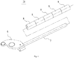
Fig. 2 is a schematic isometric view of a traction device according to an embodiment of the present disclosure; -
Fig. 3 is a partial enlarged view of a portion A inFig. 2 ; -
Fig. 4 is a schematic structural view of a front swing arm of a traction device according to an embodiment of the present disclosure; -
Fig. 5 is a schematic top view of a traction device according to an embodiment of the present disclosure; -
Fig. 6 is a schematic cross-sectional view taken along line B-B ofFig. 5 ; -
Fig. 7 is a schematic cross-sectional view taken along line C-C ofFig. 5 ; -
Fig. 8 is a schematic cross-sectional view taken along line D-D ofFig. 5 ; -
Fig. 9 is a schematic view showing a use state of a traction device according to an embodiment of the present disclosure; -
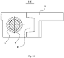
Fig. 10 is a schematic cross-sectional view taken along line E-E inFig. 9 . - In the drawings, the same components are denoted by the same reference numerals. The drawings are not drawn to scale.
- Implementations of the present disclosure will be further described in detail below with reference to the accompanying drawings and embodiments. The detailed description of the embodiments and the accompanying drawings are intended to exemplarily illustrate the principle of the present disclosure and not to limit the scope of the present disclosure. That is, the present disclosure is not limited to the described embodiments.
- In the description of the present disclosure, it should be noted that, unless otherwise stated, the meaning of "several" is one or more; the meaning of "multiple" is two or more; orientations or positional relationship indicated by the terms "above", "below", "left", "right", "in", "out", "front end", "rear end", "head", "tail", etc., refer to the orientations or positional relationships as shown in the drawings, are used merely for facilitating and simplifying the description of the present disclosure, instead of indicating or implying the device or component referred to must have a particular orientation, be constructed and operated in the particular orientation, and thus shall not be construed as limiting the present disclosure.
- As shown in
Fig. 1 , atraction device 1 according to an embodiment of the present disclosure is used to tow a vehicle in an unpowered state to move. When towing the vehicle by thetraction device 1, thetraction device 1 is first placed on the ground below a chassis of the vehicle, and then aswing arm 2 of thetraction device 1 is deployed and brought into contact with a circumferential surface of awheel 99. Then, thetraction device 1 is coupled to an external driving device (such as a tractor). The driving device can drive thewheel 99 of the vehicle to roll by means of theswing arm 2 of thetraction device 1, so that the entire vehicle can travel on a support surface, such as the ground. - As shown in
Fig. 2 , thetraction device 1 according to an embodiment of the present disclosure includes asupport chassis 3. Thesupport chassis 3 includes a front end, a rear end, and an intermediate portion. The front end of thesupport chassis 3 is provided with atraction portion 4, and the rear end is provided with a traveling roller assembly 5. The external driving device applies a driving force to thetraction device 1 via thetraction portion 4. The traveling roller assembly 5 can support thetraction device 1 and reduce a movement resistance of thetraction device 1, so that thetraction device 1 can be dragged to move with a less labor, thereby improving use convenience of the traction device. - The
traction portion 4 according to the present embodiment includes a connectingshaft 41 disposed on thesupport chassis 3 and atraction piece 42 pivotally connected to the connectingshaft 41. The front end of thesupport chassis 3 is provided with two pairs ofsupport plates 31 extending outward. Thesupport plate 31 is arc-shaped. The two pairs ofsupport plates 31 are disposed symmetrically with respect to acentral axis 32 of thesupport chassis 3. Each of thesupport plates 31 is provided with one connectingshaft 41. Thetraction piece 42 includes a connecting portion and two protruding portions disposed side by side on the connecting portion. The connecting portion is used for coupling with the external driving device. The protruding portions are pivotally connected to the connectingshafts 41, such that thetraction piece 42 can rotate around the connectingshafts 41 as a whole, thereby facilitating an operator to adjust a position of the connecting portion and couple the connecting portion with the external driving device. - In one embodiment, the front end of the
support chassis 3 is provided with three or more pairs ofsupport plates 31. Each pair ofsupport plates 31 is provided with one connectingshaft 41. Alternatively, there is only one connectingshaft 41, and the connectingshaft 41 is inserted into all of thesupport plates 31, which can increase a rigidity of thetraction portion 4, such that thetraction device 1 can bear a larger tractive force and thus can drive a vehicle having a greater weight. - The traveling roller assembly 5 according to the present embodiment includes two roller carriers 51 connected to the rear end of the
support chassis 3 by means of screws. The two roller carriers 51 are disposed symmetrically with respect to thecentral axis 32 of thesupport chassis 3, such that thetraction device 1 is balanced in a use state, thereby ensuring a stabilization of a position of thesupport chassis 3. Each roller carrier 51 is provided with two rollers 52, which can increase the number of fulcrums on the support surface, and thus improve the stabilization of position and load carrying capacity of theentire traction device 1. When thetraction device 1 is in use, only outer peripheral surfaces of the rollers 52 are in direct contact with the support surface, which can reduce a frictional resistance between thetraction device 1 and the support surface. - In one embodiment, the rear end of the
support chassis 3 is provided with only one roller carrier 51, and one roller 52 having a larger diameter is mounted on the roller carrier 51. The rear end of thesupport chassis 3 may be provided with more than two roller carriers 51, and each roller carrier 51 is provided with one roller 52, or more than two rollers 52. - The
swing arm 2 of thetraction device 1 according to the present embodiment further includes twofront swing arms 21 and tworear swing arms 22 disposed at the intermediate portion of thesupport chassis 3. The twofront swing arms 21 are disposed symmetrically with respect to thecentral axis 32 of thesupport chassis 3, and the same is true for the tworear swing arms 22. Both of the twofront swing arms 21 and the tworear swing arms 22 are connected to thesupport chassis 3 via respectiverotating shafts 98, and eachrotating shaft 98 has an axis perpendicular to thesupport chassis 3. Both of the twofront swing arms 21 and the tworear swing arms 22 are rotatable about the respectiverotating shafts 98 to rotate horizontally, such that both of thefront swing arms 21 and therear swing arms 22 can be switched between a retracted state (as shown inFig. 2 orFig. 5 ) and a deployed state (as shown inFig. 9 ). When thefront swing arm 21 or therear swing arm 22 is switched from the deployed state to the retracted state, thefront swing arm 21 or therear swing arm 22 moves close to thesupport chassis 3, and conversely, when thefront swing arm 21 or therear swing arm 22 is switched from the retracted state to the deployed state, thefront swing arm 21 or therear swing arm 22 moves away from thesupport chassis 3. When thefront swing arm 21 and therear swing arm 22 are in the retracted state, axes of thefront swing arm 21 and therear swing arm 22 are both parallel to thecentral axis 32 of thesupport chassis 3. When thefront swing arm 21 and therear swing arm 22 are in the deployed state, the axes of thefront swing arm 21 and therear swing arm 22 are both perpendicular to thecentral axis 32 of thesupport chassis 3. - When towing the vehicle by using the
traction device 1 according to the embodiment of the present disclosure, after thetraction device 1 is placed on the support surface below the chassis of the vehicle, thefront swing arm 21 and therear swing arm 22 are operated to transition from the retracted state to the deployed state, thereby holding thewheel 99 of the vehicle therebetween. When thetraction device 1 is driven to move, therear swing arm 22 applies a driving force to thewheel 99 of the vehicle located between thefront swing arm 21 and therear swing arm 22 to rotate thewheel 99, thereby towing the entire vehicle to move forward. Thewheel 99 of the vehicle located between thefront swing arm 21 and therear swing arm 22 is restricted by thefront swing arm 21 and therear swing arm 22, and thus, accidental turning of thewheel 99 is less likely to occur, thereby ensuring that the vehicle moves along a predetermined route, and that the towing operation is smoothly completed. When the vehicle being towed is dragged to a predetermined position, thefront swing arm 21 can buffer an inertial movement of the vehicle so that the vehicle stops at the predetermined position, and an occurrence of a sliding of the vehicle can be avoided. After the vehicle is stopped completely, thefront swing arm 21 and therear swing arm 22 can be transitioned from the deployed state to the retracted state to release thewheel 99. Finally, thetraction device 1 is pulled out from a space below the vehicle, for towing the next vehicle. - The
front swing arm 21 has a same configuration as therear swing arm 22 according to the present embodiment, and thus, merely the configuration of thefront swing arm 21 will be described here. As shown inFigs. 4 and6 , thefront swing arm 21 includes a connectingend portion 6 connected to therotating shaft 98, anarm 7 connected to the connectingend portion 6, and a rotatingmember 8 sleeved on thearm 7. The connectingend portion 6 is formed in a plate-like shape, and provided with a counterbore. Thesupport chassis 3 is provided with a pin hole. A shaft sleeve is disposed in the pin hole. The rotatingshaft 98 is inserted into the counterbore and the shaft sleeve to connect thefront swing arm 21 with thesupport chassis 3. The shaft sleeve can protect the pin hole, to prevent therotating shaft 98 from directly contacting with the pin hole and thus wearing the pin hole. Thearm 7 is formed in a straight rod shape. The rotatingmember 8 is a bearing or a nylon sleeve. After sleeving at least one bearing or nylon sleeve on the straight rod-shapedarm 7, a screw with a retaining ring is mounted on a free end of thearm 7, and the screw is tightened so that the retaining ring presses against the bearing or the nylon sleeve, thereby preventing the bearing or the nylon sleeve from coming off thearm 7. - Further, when the
rear swing arm 22 drives thewheel 99 to rotate, therotating wheel 99 drives the bearing or the nylon sleeve mounted on thearm 7 of therear swing arm 22 to rotate, thereby reducing a resistance encountered when thewheel 99 rotates. In the case that a frictional force between thewheel 99 and thearm 7 has a too large component force perpendicular to the support surface, thearm 7 will move perpendicularly to the support surface, bend and deform, even disconnect from thesupport chassis 3 due to the component force. Therefore, the bearing or the nylon sleeve can prevent thewheel 99 from directly rubbing against thearm 7, thereby protecting thearm 7, avoiding the above-mentioned disadvantages and prolonging a service life of thearm 7. - As shown in
Fig. 2 , thetraction device 1 according to the present embodiment further includes a driving mechanism 9. The driving mechanism 9 of the present embodiment is a hydraulic cylinder. Two ends of the hydraulic cylinder are respectively connected to the connectingend portions 6 of thefront swing arm 21 and therear swing arm 22 by pins. In the case that thefront swing arm 21 and therear swing arm 22 are in the retracted state, the axes of thefront swing arm 21 and therear swing arm 22 are substantially parallel to an axis of the hydraulic cylinder. As such, the hydraulic cylinder can synchronously drive thefront swing arm 21 and therear swing arm 22, and thefront swing arm 21 and therear swing arm 22 can synchronously reach the final deployed state or the retracted state. The hydraulic cylinder is driven by an external hydraulic pumping station to make a telescopic movement, so as to control the deployment and retraction of thefront swing arm 21 and therear swing arm 22. In the case that thefront swing arm 21 and therear swing arm 22 are in the deployed state, the hydraulic cylinder provides a supporting force for therear swing arm 22 to resist a force applied on therear swing arm 22 by thewheel 99, and also avoid an accidental retraction of therear swing arm 22 under a reaction force from thewheel 99. - In one embodiment, the hydraulic cylinders are provided between the connecting
end portions 6 of the twofront swing arms 21, and between the connectingend portions 6 of the tworear swing arms 22, respectively. The two independent hydraulic cylinders can operate independently, and ensure that the twofront swing arms 21 and/or the tworear swing arms 22 can be synchronously deployed or retracted. - The hydraulic cylinder according to the present embodiment is an oil cylinder, and the
support chassis 3 is provided with an oil circuit system, to facilitate a supply of oil to the oil cylinder by an external oil pumping station. - In one embodiment, the driving mechanism 9 may be an electric push rod or other telescopic mechanism that can perform the same function.
- As shown in
Fig. 5 andFig. 7 , thesupport chassis 3 according to the present embodiment is provided withretraction limit portions 10 on both sides near the front end and the rear end. In the case that theswing arm 21 and therear swing arm 22 are in the retracted state, theretraction limit portion 10 is located between thefront swing arm 21 and thesupport chassis 3 or between therear swing arm 22 and thesupport chassis 3, to space thefront swing arm 21 or therear swing arm 22 apart from thesupport chassis 3, and prevent thefront swing arm 21 or therear swing arm 22 from crossing over an optimal retracted position and colliding and rubbing with thesupport chassis 3, thereby protecting thesupport chassis 3, thefront swing arm 21 and therear swing arm 22. Theretraction limit portion 10 includes a receiving groove configured to match with an outer peripheral surface of thefront swing arm 21 or therear swing arm 22, so as to ensure a larger contact area between thefront swing arm 21 or therear swing arm 22 in the retracted state and the receiving groove, a much better conformation of thefront swing arm 21 or therear swing arm 22 in the retracted state to the receiving groove, and thus a much more stable position of thefront swing arm 21 and therear swing arm 22 in the retracted state. An opening size of the receiving groove of theretraction limit portion 10 is equal to or less than a maximum radial dimension of thefront swing arm 21 or therear swing arm 22. Theretraction limit portion 10 may be formed by a projection extending outward from the side of thesupport chassis 3, or may be a separate member that is mounted and fixedly connected to the side of thesupport chassis 3. Thearms 7 and therotating members 8 of thefront swing arm 21 and therear swing arm 22 in the present embodiment are both circular in cross section, and the receiving groove has a cross section with an outline of an arc less than or equal to one-half of a circumference. - As shown in
Figs. 3 and5 , thesupport chassis 3 of the present embodiment is provided with adeployment limit portion 11 on the side at the intermediate portion. Thedeployment limit portion 11 is disposed on a moving path of thefront swing arm 21 or therear swing arm 22. When thefirst swing arm 21 or therear swing arm 22 is transitioned from the retracted state to the deployed state and contacts with thedeployment limit portion 11, thedeployment limit portion 11 can restrict thefront swing arm 21 or therear swing arm 22 from continuing to deploy, such that thefront swing arm 21 or therear swing arm 22 is stopped at a predetermined deployed position, thereby preventing thefront swing arm 21 or therear swing arm 22 from being deployed over the predetermined deployed position. As such, it can be avoided that thewheel 99 of the vehicle cannot be received between thefront swing arm 21 and therear swing arm 22, or that therear swing arm 22 cannot be perpendicular to thecentral axis 32 of thesupport chassis 3 such that an outer peripheral surface of the rotatingmember 8 of therear swing arm 22 cannot completely contact with the outer surface of thewheel 99 in an axial direction (that is, a part of the outer peripheral surface of the rotatingmember 8 contacts with thewheel 99, while the remaining part is separated from thewheel 99 with a gap). When the outer peripheral surface of the rotatingmember 8 on therear swing arm 22 does not completely contact with the outer surface of thewheel 99 in the axial direction, the force applied to thewheel 99 by therear swing arm 22 may be deviated, and a stress concentration may occur. In the case that the force applied by therear swing arm 22 to thewheel 99 is deviated, during the rotation of thewheel 99, thewheel 99 will turn and cannot travel in a straight line, which may result in unsmooth towing operation, even a failure of the towing operation. In the case that the force applied to thewheel 99 by therear swing arm 22 brings the stress concentration on the rotatingmember 8, therear swing arm 22 may be bent and deformed, and thus may be damaged. Therefore, thedeployment limit portion 11 ensures that the deployment of therear swing arm 22 is stopped when reaching the predetermined deployment position, where therear swing arm 22 is perpendicular to thecentral axis 32 of thesupport chassis 3, thereby ensuring that the outer peripheral surface of the rotatingmember 8 completely contacts with thewheel 99, so that therear swing arm 22 can drive thewheel 99 to travel substantially in a straight line, and that therear swing arm 22 is evenly balanced to avoid the aforementioned adverse effects. - As shown in
Figs. 3 and10 , thedeployment limit portion 11 of the present embodiment includes a wedge-shapedgroove 111, and an axis of the wedge-shapedgroove 111 is perpendicular to thecentral axis 32 of thesupport chassis 3 and is located in a horizontal plane. Thefront swing arm 21 or therear swing arm 22 is provided with a wedge-shapedpiece 12. During deployment of thefront swing arm 21 or therear swing arm 22, the wedge-shapedpiece 12 on thefront swing arm 21 or therear swing arm 22 gradually engages with the wedge-shapedgroove 111 and finally completely conforms to the wedge-shapedgroove 111. During the gradual engagement of the wedge-shapedpiece 12 with the wedge-shapedgroove 111, the wedge-shapedgroove 111 can limit a position of the wedge-shapedpiece 12, and guide the wedge-shapedpiece 12 to engage with the wedge-shapedgroove 111. As such, thedeployment limit portion 11 can adjust the deployment position of thefront swing arm 21 or therear swing arm 22 by use of the wedge-shapedpiece 12, such that thefront swing arm 21 or therear swing arm 22 is located at a horizontal position when in the deployed state. In the case that thefront swing arm 21 or therear swing arm 22 is deformed (for example, the connectingend portion 6 is tilted upward while a free end of thearm 7 droops), thefront swing arm 21 or therear swing arm 22 is not located at the horizontal position. However, by means of the engagement of the wedge-shapedpiece 12 with the wedge-shapedgrove 111, thefront swing arm 21 or therear swing arm 22 can be eventually adjusted to the horizontal position. Further, thedeployment limit portion 11 can support thefront swing arm 21 or therear swing arm 22 in the deployed state, so as to ensure the stabilization of the position of thefront swing arm 21 or therear swing arm 22 in the deployed state. - The
deployment limit portion 11 of the present embodiment may be a protruding portion extending outward from the side of thesupport chassis 3, and a wedge-shapedgroove 111 may be provided at a top of the protruding portion. Alternatively, thedeployment limit portion 11 may be a separate member fixedly connected to the side of thesupport chassis 3 by screws, and the wedge-shapedgroove 111 is provided on the separate member. - As shown in
Figs. 3 and8 , thesupport chassis 3 of the present embodiment is further provided with a rollingassembly 13 on the side. The rollingassembly 13 is disposed between thedeployment limit portion 11 of thefront swing arm 21 and thedeployment limit portion 11 of therear swing arm 22. The rollingassembly 13 includes astationary shaft 131 and aroller 132 pivotally connected to thestationary shaft 131. In the present embodiment, fourrollers 132 are provided to increase a coverage area and thus ensure that therollers 132 can contact with thewheel 99. When therear swing arm 22 drives thewheel 99 to rotate forward, thewheel 99 may turn occasionally and theturning wheel 99 will come into contact with theroller 132 and drives theroller 132 to rotate. Therotating roller 132 can guide thewheel 99, thereby preventing a direct and hard friction between thewheel 99 and thesupport chassis 3, ensuring the smooth travelling of thewheel 99, and protecting the side of thesupport chassis 3 from being damaged. - A width of the
support chassis 3 of the present embodiment is smaller than a distance between inner sides of twoopposite wheels 99 on left and right sides of the vehicle, so that thesupport chassis 3 can be smoothly moved into or out of the space below the vehicle. When thefront swing arm 21 and therear swing arm 22 are in the deployed state, a distance between free ends of the twofront swing arms 21 or a distance between free ends of the tworear swing arms 22 is greater than or equal to a distance between outer sides of the twoopposite wheels 99, thereby ensuring that thefront swing arm 21 or therear swing arm 22 can completely contact with thewheel 99. - The embodiment of the present disclosure further relates to a traction method by using the
traction device 1 according to the embodiment of the present disclosure. The method can be performed as follows: at first, parking the vehicle to be towed in a predetermined area; then, pushing thesupport chassis 3 of thetraction device 1 into a space below the chassis of the vehicle to be towed; actuating the driving mechanism 9 to deploy thefront swing arm 21 and therear swing arm 22, such that thewheel 99 is restricted between thefront swing arm 21 and therear swing arm 22; after thefront swing arm 21 and therear swing arm 22 are deployed to the predetermined deployment positions, coupling thetraction portion 4 of thetraction device 1 to a tractor; starting the tractor to drag thetraction device 1, so that therear swing arm 22 drives thewheel 99 to rotate and thus drive the vehicle to travel, and eventually tow the vehicle to a predetermined position; and after the vehicle arrives at the predetermined position, stopping the tractor, and under the buffering of thefront swing arm 21, the vehicle will not continue to travel under the inertia, and thus the vehicle to be towed is accurately parked at the predetermined position. - After the vehicle is stopped completely, the driving mechanism 9 is activated to retract the
front swing arm 21 and therear swing arm 22 to release thewheel 99. After thefront swing arm 21 and therear swing arm 22 are fully returned to the retracted state, the tractor is started to pull thetraction device 1 out of the space below the vehicle. Then, the traction device is moved back to the predetermined area to pull the next vehicle. - In one embodiment, it comes first that the vehicle to be towed is parked in a predetermined area, and secondly, the
traction portion 4 of thetraction device 1 is coupled to the tractor. Then, the tractor drives thetraction device 1 and pushes thetraction device 1 to the space below the chassis of the vehicle to be towed, and the deployment operation of thefront swing arm 21 and therear swing arm 22 is then performed. - The
traction device 1 of the present embodiment drives a front wheel of the vehicle to rotate by therear swing arm 22 to tow the vehicle. Thetraction device 1 of the present embodiment can also drive a rear wheel of the vehicle to rotate by therear swing arm 22. Alternatively, thetraction device 1 of the present embodiment can be provided with two sets offront swing arms 21 and two sets ofrear swing arms 22, and drives the front wheel and the rear wheel of the vehicle to rotate synchronously. Thetraction device 1 of the present embodiment can be provided with only therear swing arm 22, and thewheel 99 also can be driven to rotate so as to tow the vehicle by therear swing arm 22. - Although the present disclosure has been described with reference to the preferred embodiments, various modifications may be made to the present disclosure and components may be replaced with equivalents without departing from the scope of the present disclosure. In particular, the technical features mentioned in the various embodiments can be combined in any manner as long as there is no structural conflict. The present disclosure is not limited to the specific embodiments disclosed herein, but includes all technical solutions falling within the scope of the claims.
Claims (15)
- A traction device for towing a vehicle, the traction device comprising:a support chassis;a swing arm, wherein one end of the swing arm is rotatably connected to the support chassis by means of a rotating shaft such that the other end of the swing arm can move close to or away from the support chassis, when the other end of the swing arm moves away from the support chassis, the swing arm is in a deployed state, and when the other end of the swing arm moves close to the support chassis, the swing arm is in a retracted state, wherein when in the deployed state, the swing arm is adapted to contact with a circumferential surface of a wheel of the vehicle so as to drive the wheel of the vehicle to rotate and tow the vehicle;a driving mechanism, connected to the swing arm, wherein the driving mechanism is capable of driving the swing arm to horizontally rotate around the rotating shaft so as to switch the swing arm between the retracted state and the deployed state; anda rolling assembly, disposed on a side of the support chassis and being capable of preventing the wheel from contacting with the side of the support chassis when the vehicle is towed.
- The traction device according to claim 1, wherein the rolling assembly comprises a stationary shaft disposed on the support chassis and a roller pivotally connected to the stationary shaft.
- The traction device according to claim 1, wherein the swing arm comprises a front swing arm and a rear swing arm, wherein the wheel of the vehicle to be towed is located between the front swing arm and the rear swing arm in the deployed state, and the rear swing arm is adapted to drive the wheel of the vehicle to rotate.
- The traction device according to claim 3, wherein the driving mechanism is adapted to drive the front swing arm and the rear swing arm to rotate synchronously, or the driving mechanism is adapted to drive the front swing arm or the rear swing arm to rotate independently.
- The traction device according to any one of claims 1 to 4, wherein the driving mechanism is a telescopic mechanism for driving the swing arm to horizontally rotate by its own telescopic movement.
- The traction device according to claim 5, wherein the telescopic mechanism is a hydraulic cylinder or an electric push rod.
- The traction device according to claim 1, wherein the side of the support chassis is provided with a retraction limit portion, and when the swing arm is in the retracted state, the retraction limit portion is located between the swing arm and the support chassis to space the swing arm and the support chassis apart from each other.
- The traction device according to claim 7, wherein the retraction limit portion comprises a receiving groove for matching with an outer surface contour of the swing arm.
- The traction device according to claim 1, wherein the side of the support chassis is provided with a deployment limit portion, and the deployment limit portion is disposed on a moving path of the swing arm for defining a position of the swing arm in the deployed state.
- The traction device according to claim 9, wherein the deployment limit portion comprises a wedge-shaped groove, and the swing arm is provided with a wedge-shaped piece for matching with the wedge-shaped groove.
- The traction device according to claim 1, wherein the swing arm comprises an arm and a rotating member sleeved on the arm in an axial direction of the arm, wherein the rotating member is capable of rotating around an axis of the arm, and the rotating member can be rotated by the rotation of the wheel.
- The traction device according to claim 11, wherein the rotating member is a bearing or a nylon sleeve.
- The traction device according to claim 1, wherein a front end of the support chassis is provided with a traction portion.
- The traction device according to claim 1, wherein a rear end of the support chassis is provided with a travelling roller assembly.
- A traction method by use of the traction device according to any of claims 1 to 14, wherein the method comprises steps of:parking the vehicle to be towed to a predetermined area;moving the support chassis into a space below the vehicle;actuating the driving mechanism to adjust the swing arm to the deployed state such that the swing arm contacts with the wheel of the vehicle;dragging the traction device, wherein the swing arm drives the wheel to rotate so as to tow the vehicle to a predetermined position;actuating the driving mechanism to adjust the swing arm to the retracted state;moving the traction device out of the space below the vehicle and moving the traction device to the predetermined area to tow the next vehicle.
Applications Claiming Priority (2)
| Application Number | Priority Date | Filing Date | Title |
|---|---|---|---|
| CN201710088614.3A CN106965635A (en) | 2017-02-17 | 2017-02-17 | Draw-gear and traction method |
| PCT/CN2018/076698 WO2018149402A1 (en) | 2017-02-17 | 2018-02-13 | Traction device and traction method |
Publications (3)
| Publication Number | Publication Date |
|---|---|
| EP3584096A1 true EP3584096A1 (en) | 2019-12-25 |
| EP3584096A4 EP3584096A4 (en) | 2020-12-09 |
| EP3584096B1 EP3584096B1 (en) | 2021-11-24 |
Family
ID=59334961
Family Applications (1)
| Application Number | Title | Priority Date | Filing Date |
|---|---|---|---|
| EP18754919.1A Not-in-force EP3584096B1 (en) | 2017-02-17 | 2018-02-13 | Traction device and traction method |
Country Status (4)
| Country | Link |
|---|---|
| US (1) | US11203239B2 (en) |
| EP (1) | EP3584096B1 (en) |
| CN (1) | CN106965635A (en) |
| WO (1) | WO2018149402A1 (en) |
Cited By (1)
| Publication number | Priority date | Publication date | Assignee | Title |
|---|---|---|---|---|
| AT525627B1 (en) * | 2021-12-15 | 2023-06-15 | Avl List Gmbh | Vehicle test stand and method for recording a vehicle on a vehicle test stand |
Families Citing this family (4)
| Publication number | Priority date | Publication date | Assignee | Title |
|---|---|---|---|---|
| CN106965635A (en) | 2017-02-17 | 2017-07-21 | 同方威视技术股份有限公司 | Draw-gear and traction method |
| CN108190402B (en) * | 2018-01-26 | 2020-12-11 | 同方威视技术股份有限公司 | Vehicle conveying device and scanning inspection system |
| CN109278790A (en) * | 2018-11-29 | 2019-01-29 | 衡阳合力工业车辆有限公司 | A clamping device and rail tractor |
| CN116653880A (en) * | 2023-05-08 | 2023-08-29 | 上汽通用五菱汽车股份有限公司 | Multifunctional Electric Trailer |
Family Cites Families (30)
| Publication number | Priority date | Publication date | Assignee | Title |
|---|---|---|---|---|
| GB1265482A (en) * | 1968-05-06 | 1972-03-01 | ||
| US3885815A (en) * | 1974-01-09 | 1975-05-27 | August A Kniff | Towing device |
| GB2089293B (en) | 1980-11-28 | 1985-05-15 | Wright John Owen | Stowable trailer |
| ZA855301B (en) * | 1984-06-12 | 1986-04-21 | ||
| US5133264A (en) * | 1991-01-22 | 1992-07-28 | Belanger, Inc. | Floor mounted automobile conveyor |
| JP3194349B2 (en) * | 1995-10-27 | 2001-07-30 | 株式会社ダイフク | Vehicle transport method and device |
| ITMO20010065A1 (en) * | 2001-04-09 | 2002-10-09 | Giuliano Srl | DEVICE TO AUTOMATICALLY MOVE VEHICLES ALONG THE LANES LIFTING POSTS |
| DE20119469U1 (en) * | 2001-11-29 | 2003-04-10 | AL-KO Kober AG, 89359 Kötz | Electric braking device for vehicle trailers |
| US7584980B2 (en) * | 2006-03-28 | 2009-09-08 | Michael Thompson | Fold up/fold down tow dolly for use with a load bearing vehicle hitch |
| CN101195378B (en) * | 2006-12-08 | 2011-08-17 | 同方威视技术股份有限公司 | Wheeled trolley for vehicle inspection |
| CN100579837C (en) * | 2006-12-31 | 2010-01-13 | 同方威视技术股份有限公司 | Self-driving trailer system and vehicle radiation imaging inspection method using the system |
| JP5524743B2 (en) * | 2010-07-13 | 2014-06-18 | 株式会社Ihi検査計測 | Cable towed vehicle conveyor |
| CN201745402U (en) | 2010-08-17 | 2011-02-16 | 启东大同电机有限公司 | Stepless adjustable gapless clamping self-locking traction hook |
| US8371599B2 (en) * | 2010-12-14 | 2013-02-12 | L. Thomas Duvall | Truck towing system and assembly |
| CN202186250U (en) | 2011-05-30 | 2012-04-11 | 赵金叶 | Lifting and shifting frame |
| CN102530791A (en) * | 2012-01-06 | 2012-07-04 | 同方威视技术股份有限公司 | Vehicle wheel identifying device |
| FR2991640B1 (en) | 2012-06-11 | 2015-12-18 | Cict | TILT TRAILER COMPRISING A SLIDING ARTICULATED TIMON. |
| US9016711B1 (en) * | 2012-10-24 | 2015-04-28 | Kendall Mathews | Trailer with trailer hitch |
| US9302543B1 (en) * | 2014-03-31 | 2016-04-05 | Quality Stainless Products, Inc. | Tire and wheel lift |
| CN104730591A (en) * | 2015-04-15 | 2015-06-24 | 同方威视技术股份有限公司 | Fixed vehicle safety inspection system |
| CN204801439U (en) * | 2015-04-15 | 2015-11-25 | 同方威视技术股份有限公司 | Vehicle draw gear |
| CN104742671B (en) * | 2015-04-15 | 2017-04-05 | 同方威视技术股份有限公司 | Vehicle tractor and vehicle traction method |
| US10486581B2 (en) * | 2015-05-25 | 2019-11-26 | Enrique Collazo | Roller-drawbar with arms for lifting |
| CN205387339U (en) * | 2015-12-28 | 2016-07-20 | 同方威视技术股份有限公司 | Vehicle draw gear and radiation imaging checkout system |
| CN205523483U (en) | 2016-04-13 | 2016-08-31 | 溧阳二十八所系统装备有限公司 | Folding jack of traction lever |
| CN206485327U (en) * | 2017-02-17 | 2017-09-12 | 同方威视技术股份有限公司 | Draw-gear |
| CN106965635A (en) | 2017-02-17 | 2017-07-21 | 同方威视技术股份有限公司 | Draw-gear and traction method |
| US10231372B2 (en) * | 2017-02-24 | 2019-03-19 | Matthew S. Pennybacker | Coupling device to connect two tractor-pulled agricultural implements for tandem-powered operation |
| MX2023009462A (en) * | 2018-07-20 | 2023-08-28 | Atc Transp Llc | LOW PROFILE TROLLEY FOR A TOW PLATFORM. |
| US11606894B2 (en) * | 2019-05-28 | 2023-03-21 | Copperhead Planter Products, Llc | Implement guidance module |
-
2017
- 2017-02-17 CN CN201710088614.3A patent/CN106965635A/en active Pending
-
2018
- 2018-02-13 EP EP18754919.1A patent/EP3584096B1/en not_active Not-in-force
- 2018-02-13 US US16/486,654 patent/US11203239B2/en not_active Expired - Fee Related
- 2018-02-13 WO PCT/CN2018/076698 patent/WO2018149402A1/en not_active Ceased
Cited By (2)
| Publication number | Priority date | Publication date | Assignee | Title |
|---|---|---|---|---|
| AT525627B1 (en) * | 2021-12-15 | 2023-06-15 | Avl List Gmbh | Vehicle test stand and method for recording a vehicle on a vehicle test stand |
| AT525627A4 (en) * | 2021-12-15 | 2023-06-15 | Avl List Gmbh | Vehicle test stand and method for recording a vehicle on a vehicle test stand |
Also Published As
| Publication number | Publication date |
|---|---|
| US11203239B2 (en) | 2021-12-21 |
| US20200055355A1 (en) | 2020-02-20 |
| EP3584096B1 (en) | 2021-11-24 |
| WO2018149402A1 (en) | 2018-08-23 |
| CN106965635A (en) | 2017-07-21 |
| EP3584096A4 (en) | 2020-12-09 |
Similar Documents
| Publication | Publication Date | Title |
|---|---|---|
| US11203239B2 (en) | Traction device and traction method | |
| CN109436972B (en) | Vehicle-mounted cable winding and unwinding mechanism and cable winding and unwinding vehicle | |
| CN104418249A (en) | Boom extension and contraction mechanism for crane apparatus | |
| WO2015083398A1 (en) | Dolly | |
| KR20190058790A (en) | Lifting trolley | |
| CN109733791A (en) | It is a kind of based on the load transmission device of laser automatic guided vehicle and transportation resources | |
| US10544023B2 (en) | Guide-roll arrangement for guiding relative movement of members of a lift-truck and a lift-truck comprising a guide-roll arrangement | |
| CN206485327U (en) | Draw-gear | |
| JP4898562B2 (en) | Rewind payoff reel | |
| JP2014201184A (en) | Coupling device of towing truck | |
| JP2525596B2 (en) | A device that winds or unwinds the flexible sheet material that is continuously fed. | |
| CN115257984B (en) | Traction device for semi-trailer | |
| NZ198960A (en) | Wheeled lifting apparatus with cam activated scissors action and high manoeuverability | |
| CN217376074U (en) | Embrace wheeled AGV dolly | |
| CN209833480U (en) | Clamping device for AGV trolley | |
| CN109552943B (en) | Winding mechanism and winding system | |
| CN117208790A (en) | Telescopic lifting arm and equipment thereof | |
| CN110482453B (en) | Coil supporting mechanism, coil transporting vehicle and coil transporting system | |
| CN211592548U (en) | Piggyback transport vehicle | |
| CN110884511B (en) | Piggyback transport vehicle | |
| CN223879286U (en) | Battery lifting appliance and battery replacing station | |
| US10549971B2 (en) | Guide-roll arrangement for guiding relative movement of mast segments of a lift-truck and a lift-truck comprising a guide-roll arrangement | |
| KR20100065820A (en) | Heavy weight moving apparatus | |
| CN222629287U (en) | Heavy load precast beam transfer robot arresting gear | |
| CN105855904B (en) | A kind of machinery processing apparatus in convenient adjustment gap |
Legal Events
| Date | Code | Title | Description |
|---|---|---|---|
| STAA | Information on the status of an ep patent application or granted ep patent |
Free format text: STATUS: THE INTERNATIONAL PUBLICATION HAS BEEN MADE |
|
| PUAI | Public reference made under article 153(3) epc to a published international application that has entered the european phase |
Free format text: ORIGINAL CODE: 0009012 |
|
| STAA | Information on the status of an ep patent application or granted ep patent |
Free format text: STATUS: REQUEST FOR EXAMINATION WAS MADE |
|
| 17P | Request for examination filed |
Effective date: 20190904 |
|
| AK | Designated contracting states |
Kind code of ref document: A1 Designated state(s): AL AT BE BG CH CY CZ DE DK EE ES FI FR GB GR HR HU IE IS IT LI LT LU LV MC MK MT NL NO PL PT RO RS SE SI SK SM TR |
|
| AX | Request for extension of the european patent |
Extension state: BA ME |
|
| DAV | Request for validation of the european patent (deleted) | ||
| DAX | Request for extension of the european patent (deleted) | ||
| A4 | Supplementary search report drawn up and despatched |
Effective date: 20201110 |
|
| RIC1 | Information provided on ipc code assigned before grant |
Ipc: B60D 1/24 20060101ALI20201104BHEP Ipc: B60D 1/42 20060101AFI20201104BHEP Ipc: B60S 13/00 20060101ALI20201104BHEP |
|
| GRAP | Despatch of communication of intention to grant a patent |
Free format text: ORIGINAL CODE: EPIDOSNIGR1 |
|
| STAA | Information on the status of an ep patent application or granted ep patent |
Free format text: STATUS: GRANT OF PATENT IS INTENDED |
|
| INTG | Intention to grant announced |
Effective date: 20210621 |
|
| GRAS | Grant fee paid |
Free format text: ORIGINAL CODE: EPIDOSNIGR3 |
|
| GRAA | (expected) grant |
Free format text: ORIGINAL CODE: 0009210 |
|
| STAA | Information on the status of an ep patent application or granted ep patent |
Free format text: STATUS: THE PATENT HAS BEEN GRANTED |
|
| AK | Designated contracting states |
Kind code of ref document: B1 Designated state(s): AL AT BE BG CH CY CZ DE DK EE ES FI FR GB GR HR HU IE IS IT LI LT LU LV MC MK MT NL NO PL PT RO RS SE SI SK SM TR |
|
| REG | Reference to a national code |
Ref country code: GB Ref legal event code: FG4D |
|
| REG | Reference to a national code |
Ref country code: AT Ref legal event code: REF Ref document number: 1449599 Country of ref document: AT Kind code of ref document: T Effective date: 20211215 |
|
| REG | Reference to a national code |
Ref country code: DE Ref legal event code: R096 Ref document number: 602018027185 Country of ref document: DE |
|
| REG | Reference to a national code |
Ref country code: IE Ref legal event code: FG4D |
|
| REG | Reference to a national code |
Ref country code: LT Ref legal event code: MG9D |
|
| REG | Reference to a national code |
Ref country code: NL Ref legal event code: MP Effective date: 20211124 |
|
| REG | Reference to a national code |
Ref country code: AT Ref legal event code: MK05 Ref document number: 1449599 Country of ref document: AT Kind code of ref document: T Effective date: 20211124 |
|
| PG25 | Lapsed in a contracting state [announced via postgrant information from national office to epo] |
Ref country code: RS Free format text: LAPSE BECAUSE OF FAILURE TO SUBMIT A TRANSLATION OF THE DESCRIPTION OR TO PAY THE FEE WITHIN THE PRESCRIBED TIME-LIMIT Effective date: 20211124 Ref country code: LT Free format text: LAPSE BECAUSE OF FAILURE TO SUBMIT A TRANSLATION OF THE DESCRIPTION OR TO PAY THE FEE WITHIN THE PRESCRIBED TIME-LIMIT Effective date: 20211124 Ref country code: FI Free format text: LAPSE BECAUSE OF FAILURE TO SUBMIT A TRANSLATION OF THE DESCRIPTION OR TO PAY THE FEE WITHIN THE PRESCRIBED TIME-LIMIT Effective date: 20211124 Ref country code: BG Free format text: LAPSE BECAUSE OF FAILURE TO SUBMIT A TRANSLATION OF THE DESCRIPTION OR TO PAY THE FEE WITHIN THE PRESCRIBED TIME-LIMIT Effective date: 20220224 Ref country code: AT Free format text: LAPSE BECAUSE OF FAILURE TO SUBMIT A TRANSLATION OF THE DESCRIPTION OR TO PAY THE FEE WITHIN THE PRESCRIBED TIME-LIMIT Effective date: 20211124 |
|
| PG25 | Lapsed in a contracting state [announced via postgrant information from national office to epo] |
Ref country code: IS Free format text: LAPSE BECAUSE OF FAILURE TO SUBMIT A TRANSLATION OF THE DESCRIPTION OR TO PAY THE FEE WITHIN THE PRESCRIBED TIME-LIMIT Effective date: 20220324 Ref country code: SE Free format text: LAPSE BECAUSE OF FAILURE TO SUBMIT A TRANSLATION OF THE DESCRIPTION OR TO PAY THE FEE WITHIN THE PRESCRIBED TIME-LIMIT Effective date: 20211124 Ref country code: PT Free format text: LAPSE BECAUSE OF FAILURE TO SUBMIT A TRANSLATION OF THE DESCRIPTION OR TO PAY THE FEE WITHIN THE PRESCRIBED TIME-LIMIT Effective date: 20220324 Ref country code: PL Free format text: LAPSE BECAUSE OF FAILURE TO SUBMIT A TRANSLATION OF THE DESCRIPTION OR TO PAY THE FEE WITHIN THE PRESCRIBED TIME-LIMIT Effective date: 20211124 Ref country code: NO Free format text: LAPSE BECAUSE OF FAILURE TO SUBMIT A TRANSLATION OF THE DESCRIPTION OR TO PAY THE FEE WITHIN THE PRESCRIBED TIME-LIMIT Effective date: 20220224 Ref country code: NL Free format text: LAPSE BECAUSE OF FAILURE TO SUBMIT A TRANSLATION OF THE DESCRIPTION OR TO PAY THE FEE WITHIN THE PRESCRIBED TIME-LIMIT Effective date: 20211124 Ref country code: LV Free format text: LAPSE BECAUSE OF FAILURE TO SUBMIT A TRANSLATION OF THE DESCRIPTION OR TO PAY THE FEE WITHIN THE PRESCRIBED TIME-LIMIT Effective date: 20211124 Ref country code: HR Free format text: LAPSE BECAUSE OF FAILURE TO SUBMIT A TRANSLATION OF THE DESCRIPTION OR TO PAY THE FEE WITHIN THE PRESCRIBED TIME-LIMIT Effective date: 20211124 Ref country code: GR Free format text: LAPSE BECAUSE OF FAILURE TO SUBMIT A TRANSLATION OF THE DESCRIPTION OR TO PAY THE FEE WITHIN THE PRESCRIBED TIME-LIMIT Effective date: 20220225 Ref country code: ES Free format text: LAPSE BECAUSE OF FAILURE TO SUBMIT A TRANSLATION OF THE DESCRIPTION OR TO PAY THE FEE WITHIN THE PRESCRIBED TIME-LIMIT Effective date: 20211124 |
|
| PG25 | Lapsed in a contracting state [announced via postgrant information from national office to epo] |
Ref country code: SM Free format text: LAPSE BECAUSE OF FAILURE TO SUBMIT A TRANSLATION OF THE DESCRIPTION OR TO PAY THE FEE WITHIN THE PRESCRIBED TIME-LIMIT Effective date: 20211124 Ref country code: SK Free format text: LAPSE BECAUSE OF FAILURE TO SUBMIT A TRANSLATION OF THE DESCRIPTION OR TO PAY THE FEE WITHIN THE PRESCRIBED TIME-LIMIT Effective date: 20211124 Ref country code: RO Free format text: LAPSE BECAUSE OF FAILURE TO SUBMIT A TRANSLATION OF THE DESCRIPTION OR TO PAY THE FEE WITHIN THE PRESCRIBED TIME-LIMIT Effective date: 20211124 Ref country code: EE Free format text: LAPSE BECAUSE OF FAILURE TO SUBMIT A TRANSLATION OF THE DESCRIPTION OR TO PAY THE FEE WITHIN THE PRESCRIBED TIME-LIMIT Effective date: 20211124 Ref country code: DK Free format text: LAPSE BECAUSE OF FAILURE TO SUBMIT A TRANSLATION OF THE DESCRIPTION OR TO PAY THE FEE WITHIN THE PRESCRIBED TIME-LIMIT Effective date: 20211124 Ref country code: CZ Free format text: LAPSE BECAUSE OF FAILURE TO SUBMIT A TRANSLATION OF THE DESCRIPTION OR TO PAY THE FEE WITHIN THE PRESCRIBED TIME-LIMIT Effective date: 20211124 |
|
| REG | Reference to a national code |
Ref country code: DE Ref legal event code: R097 Ref document number: 602018027185 Country of ref document: DE |
|
| REG | Reference to a national code |
Ref country code: DE Ref legal event code: R119 Ref document number: 602018027185 Country of ref document: DE |
|
| PG25 | Lapsed in a contracting state [announced via postgrant information from national office to epo] |
Ref country code: MC Free format text: LAPSE BECAUSE OF FAILURE TO SUBMIT A TRANSLATION OF THE DESCRIPTION OR TO PAY THE FEE WITHIN THE PRESCRIBED TIME-LIMIT Effective date: 20211124 |
|
| PLBE | No opposition filed within time limit |
Free format text: ORIGINAL CODE: 0009261 |
|
| STAA | Information on the status of an ep patent application or granted ep patent |
Free format text: STATUS: NO OPPOSITION FILED WITHIN TIME LIMIT |
|
| REG | Reference to a national code |
Ref country code: CH Ref legal event code: PL |
|
| REG | Reference to a national code |
Ref country code: BE Ref legal event code: MM Effective date: 20220228 |
|
| GBPC | Gb: european patent ceased through non-payment of renewal fee |
Effective date: 20220224 |
|
| PG25 | Lapsed in a contracting state [announced via postgrant information from national office to epo] |
Ref country code: LU Free format text: LAPSE BECAUSE OF NON-PAYMENT OF DUE FEES Effective date: 20220213 Ref country code: AL Free format text: LAPSE BECAUSE OF FAILURE TO SUBMIT A TRANSLATION OF THE DESCRIPTION OR TO PAY THE FEE WITHIN THE PRESCRIBED TIME-LIMIT Effective date: 20211124 |
|
| 26N | No opposition filed |
Effective date: 20220825 |
|
| PG25 | Lapsed in a contracting state [announced via postgrant information from national office to epo] |
Ref country code: SI Free format text: LAPSE BECAUSE OF FAILURE TO SUBMIT A TRANSLATION OF THE DESCRIPTION OR TO PAY THE FEE WITHIN THE PRESCRIBED TIME-LIMIT Effective date: 20211124 |
|
| PG25 | Lapsed in a contracting state [announced via postgrant information from national office to epo] |
Ref country code: FR Free format text: LAPSE BECAUSE OF NON-PAYMENT OF DUE FEES Effective date: 20220228 |
|
| PG25 | Lapsed in a contracting state [announced via postgrant information from national office to epo] |
Ref country code: LI Free format text: LAPSE BECAUSE OF NON-PAYMENT OF DUE FEES Effective date: 20220228 Ref country code: IE Free format text: LAPSE BECAUSE OF NON-PAYMENT OF DUE FEES Effective date: 20220213 Ref country code: GB Free format text: LAPSE BECAUSE OF NON-PAYMENT OF DUE FEES Effective date: 20220224 Ref country code: DE Free format text: LAPSE BECAUSE OF NON-PAYMENT OF DUE FEES Effective date: 20220901 Ref country code: CH Free format text: LAPSE BECAUSE OF NON-PAYMENT OF DUE FEES Effective date: 20220228 |
|
| PG25 | Lapsed in a contracting state [announced via postgrant information from national office to epo] |
Ref country code: BE Free format text: LAPSE BECAUSE OF NON-PAYMENT OF DUE FEES Effective date: 20220228 |
|
| PG25 | Lapsed in a contracting state [announced via postgrant information from national office to epo] |
Ref country code: IT Free format text: LAPSE BECAUSE OF FAILURE TO SUBMIT A TRANSLATION OF THE DESCRIPTION OR TO PAY THE FEE WITHIN THE PRESCRIBED TIME-LIMIT Effective date: 20211124 |
|
| PG25 | Lapsed in a contracting state [announced via postgrant information from national office to epo] |
Ref country code: MK Free format text: LAPSE BECAUSE OF FAILURE TO SUBMIT A TRANSLATION OF THE DESCRIPTION OR TO PAY THE FEE WITHIN THE PRESCRIBED TIME-LIMIT Effective date: 20211124 Ref country code: CY Free format text: LAPSE BECAUSE OF FAILURE TO SUBMIT A TRANSLATION OF THE DESCRIPTION OR TO PAY THE FEE WITHIN THE PRESCRIBED TIME-LIMIT Effective date: 20211124 |
|
| PG25 | Lapsed in a contracting state [announced via postgrant information from national office to epo] |
Ref country code: HU Free format text: LAPSE BECAUSE OF FAILURE TO SUBMIT A TRANSLATION OF THE DESCRIPTION OR TO PAY THE FEE WITHIN THE PRESCRIBED TIME-LIMIT; INVALID AB INITIO Effective date: 20180213 |
|
| PG25 | Lapsed in a contracting state [announced via postgrant information from national office to epo] |
Ref country code: MT Free format text: LAPSE BECAUSE OF FAILURE TO SUBMIT A TRANSLATION OF THE DESCRIPTION OR TO PAY THE FEE WITHIN THE PRESCRIBED TIME-LIMIT Effective date: 20211124 |
|
| PG25 | Lapsed in a contracting state [announced via postgrant information from national office to epo] |
Ref country code: TR Free format text: LAPSE BECAUSE OF FAILURE TO SUBMIT A TRANSLATION OF THE DESCRIPTION OR TO PAY THE FEE WITHIN THE PRESCRIBED TIME-LIMIT Effective date: 20211124 |