EP3583908B1 - Zahnärztliches instrument mit flexiblem spitzenende und verfahren zur herstellung - Google Patents
Zahnärztliches instrument mit flexiblem spitzenende und verfahren zur herstellung Download PDFInfo
- Publication number
- EP3583908B1 EP3583908B1 EP19167900.0A EP19167900A EP3583908B1 EP 3583908 B1 EP3583908 B1 EP 3583908B1 EP 19167900 A EP19167900 A EP 19167900A EP 3583908 B1 EP3583908 B1 EP 3583908B1
- Authority
- EP
- European Patent Office
- Prior art keywords
- tip end
- shank
- distal portion
- flexible tip
- aperture
- Prior art date
- Legal status (The legal status is an assumption and is not a legal conclusion. Google has not performed a legal analysis and makes no representation as to the accuracy of the status listed.)
- Active
Links
Images

Classifications
-
- A—HUMAN NECESSITIES
- A61—MEDICAL OR VETERINARY SCIENCE; HYGIENE
- A61C—DENTISTRY; APPARATUS OR METHODS FOR ORAL OR DENTAL HYGIENE
- A61C13/00—Dental prostheses; Making same
- A61C13/0028—Instruments or appliances for wax-shaping or wax-removing
-
- A—HUMAN NECESSITIES
- A61—MEDICAL OR VETERINARY SCIENCE; HYGIENE
- A61C—DENTISTRY; APPARATUS OR METHODS FOR ORAL OR DENTAL HYGIENE
- A61C3/00—Dental tools or instruments
-
- A—HUMAN NECESSITIES
- A61—MEDICAL OR VETERINARY SCIENCE; HYGIENE
- A61B—DIAGNOSIS; SURGERY; IDENTIFICATION
- A61B90/00—Instruments, implements or accessories specially adapted for surgery or diagnosis and not covered by any of the groups A61B1/00 - A61B50/00, e.g. for luxation treatment or for protecting wound edges
- A61B90/08—Accessories or related features not otherwise provided for
- A61B2090/0817—Spatulas or spatula like extensions
Definitions
- the present disclosure relates generally to dental instruments and, more particularly, to dental instruments having a flexible tip end.
- Dental instruments can be used to manipulate various materials which are placed, shaped, and sculpted during procedures. Point flexibility for these instruments is desirable as flexibility aids tremendously in the sculpting and shaping of the material. Commonly, instruments of these types can be manufactured from steel. Given the metallurgic properties of steel, however, manufacturing instruments from steel results in relatively rigid points. Further, if steel points are thinned and used to manipulate materials in the desired manner, the points can break over time, if not immediately, making them potentially unsafe to use.
- a dental instrument with a bend shank and a steel blade is known form US 3 367 335 A .
- a dental instrument in accordance with a first aspect of the disclosure, includes a handle and a two-piece tip attached to the handle.
- the two-piece tip includes a shank including a distal portion with an end surface having a slot, where the distal portion extends along a longitudinal axis.
- the distal portion further has an aperture extending therethrough in a direction generally orthogonal to the longitudinal axis.
- the two-piece tip further includes a flexible tip end having a portion that is inserted within the slot, where the portion includes an aperture that extends therethrough.
- a pin is configured to be inserted through the apertures of the distal portion and the flexible tip end to secure the flexible tip end to the shank.
- the shank can have a bent configuration, which in further forms can include first and second bends within a horizontal plane.
- the flexible tip has a spatula configuration and can be made of Nickel Titanium (NiTi) foil.
- the apertures and pin can be sized relative to one another to create an interference fit and/or can have cylindrical configurations.
- the apertures are first apertures
- the pin is a first pin
- the dental instrument further includes a second aperture that extends through the distal portion in a direction generally orthogonal to the longitudinal axis, where the second aperture is spaced from the first aperture along a length of the distal portion.
- a second aperture of the flexible tip end that extends through the portion thereof is also included, where the second aperture is spaced from the first aperture along a length of the portion.
- the dental instrument of this form further includes a second pin that is configured to be inserted through the second apertures of the distal portion and the flexible tip end to secure the flexible tip end to the shank.
- the two-piece tip is a first two piece tip with a first shank and a first flexible tip end
- handle includes opposing first and second ends, where the first two-piece tip is coupled to the first end.
- the dental instrument further includes a second two-piece tip that is attached to the second end of the handle.
- the second two-piece tip including a second shank including a distal portion with an end surface having a slot, where the distal portion extends along a second longitudinal axis, and an aperture that extends through the distal portion in a direction generally orthogonal to the second longitudinal axis.
- the second two-piece tip further includes a second flexible tip end having a portion inserted within the slot, the portion including an aperture extending therethrough, and a second pin that is configured to be inserted through the apertures of the distal portion and the second flexible tip end to secure the second flexible tip end to the second shank.
- a dental instrument in accordance with a second aspect of the disclosure, includes a handle and a two-piece tip attached to the handle.
- the two-piece tip includes a steel shank with a distal portion having an end surface having a slot, where the distal portion extends along a longitudinal axis.
- the dental instrument further includes a NiTi foil tip end having a portion coupled to the distal portion of the shank. A material is disposed between the portion of the NiTi foil tip end and the distal portion to secure the NiTi foil tip end to the steel shank.
- the material is one of a filler metal to secure the NiTi foil tip end to the steel shank with a brazing process or an adhesive.
- the end surface of the distal portion can include a slot, and the portion of the NiTi foil tip end can be inserted within the slot.
- a method of manufacturing a dental instrument includes providing a handle and a two-piece tip attached to the handle.
- the two-piece tip includes a shank that includes a distal portion with an end surface having a slot, the distal portion extending along a longitudinal axis, and an aperture that extends through the distal portion in a direction generally orthogonal to the longitudinal axis.
- the method further includes inserting a portion of a flexible tip end into the slot so that an aperture extending through the portion aligns with the aperture of the distal portion and inserting a pin through the apertures of the distal portion and the flexible tip end to secure the flexible tip end to the shank.
- the method can include one or more of: forming the aperture through the distal portion in a direction generally orthogonal to the longitudinal axis, forming the aperture through the portion of the flexible tip end, or forming the slot through the end surface and into the distal portion of the shank along the longitudinal axis thereof.
- the method further includes bending the distal portion of the shank to create at least one bend.
- providing the two-piece tip includes providing the shank with first and second apertures spaced from one another and extending through the distal portion in a direction generally orthogonal to the longitudinal axis. Inserting the portion of the flexible tip end into the slot can include inserting a portion of the flexible tip end into the slot so that first and second apertures extending through the portion align with the first and second apertures of the distal portion, respectively. Further in this form, inserting the pin through the apertures of the distal portion and the flexible tip end includes inserting first and second pins through the first and second apertures, respectively, of the distal portion and the flexible tip end to secure the flexible tip end to the shank.
- a method of manufacturing a dental instrument includes providing a flexible tip end including a retaining portion and forming a shank with a distal portion coupled to the retaining portion of the flexible tip end to secure the flexible tip end to the shank.
- the method includes one or more of: providing a flexible tip end including an aperture extending therethrough, 3D printing the shank around the retaining portion of the flexible tip end, injection molding the shank around the retaining portion of the flexible tip end, forming a shank in a bent configuration, forming a handle with the shank at one end of the handle, and deforming the distal portion of the shank to clamp down on the retaining portion of the flexible tip end to secure the flexible tip end to the shank.
- the shank can be a stiff material, such as stainless steel
- the tip end can be a NiTi foil, also known as Nitinol foil.
- Nitinol foil advantageously provides a flexible tip that resiliently bends without breaking.
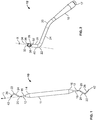
- the dental instrument 10 includes a handle portion 11 having a shaft configuration for a user to grip and manipulate the dental instrument 10.
- the handle portion 11 has opposite first and second ends 14, 16 that can be configured to have a shank 12 coupled thereto, if desired.
- the first and second ends 14, 16 have a tapered configuration to provide a transition to the relatively smaller diameter of the shank 12.
- FIG. 2 An example shank 12 is shown in Fig. 2 that includes a coupling end portion 17 configured to engage one of the ends 14, 16 of the handle 11, a tapering portion 18, first and second bends 20, 22, an intermediate portion 24 extending between the first and second bends 20, 22, and a distal portion 26 extending from the second bend 22 to a distal end 28 of the shank 12.
- the tapering portion 18 decreases a diameter of the shank 12 from adjacent to the handle 11 to the relatively smaller diameter intermediate and distal portions 24, 26, which can have a generally constant diameter.
- the first bend 20 directs the shank 12 along a horizontal plane away from a longitudinal axis L ( Fig. 1 ) of the handle 11 and the second bend 22 directs the shank 10 along the horizontal plane back towards the longitudinal axis L of the handle 11.
- the second bend 22 is a generally 90 degree bend and the intermediate portion 24 has a longer longitudinal length than the distal portion 26, such that the distal end 28 of the shank 10 is spaced from the longitudinal axis L of the handle 11 along the horizontal plane.
- other bend and length configurations are within the scope of this disclosure.
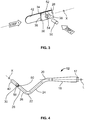
- the distal end 28 of the shank 12 includes opposing planar sides 30 extending inwardly with respect to one another to a rectangular end surface 32. With the distal portion 26 being cylindrical, in the illustrated form, the planar sides 30 have a parabolic shape.
- a slot 34 with an opening 36 disposed along the end surface 32 extends within the distal portion 26 along a longitudinal axis X ( Fig. 2 ) thereof to a desired depth. In the illustrated form, the slot 34 extends through the width of the distal end 28. In one example, and as depicted in Fig. 3 , the slot 34 may further include openings 38 along an exterior 40 of the distal portion 26.
- the slot 34 can be cut into the distal end 28 of the shank 12 in a hatchet and/or hoe orientation by an electric discharge machining (EDM) wire, micro saw blade, mill, and so forth.
- EDM electric discharge machining
- a tip end 42 is coupled to the distal end 28 of the shank 12 to provide desirable characteristics for a particular dental procedure.
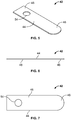
- the tip end 42 is a spatula tip having a thin planar body 44 with a curved forward portion 46 and a rectangular rear portion 48.
- the shank 12 and tip end 42 are different materials and, as such, are secured together with a suitable method, examples of which are described below with reference to Figs. 2-10 .
- the tip end 42 also includes an aperture 54 extending through the rear portion 48 and corresponds to an aperture in the distal end 28 of the shank 12, as described more below.
- the tip end 42 is inserted into the slot 34 to mount to the distal end 28 of the shank 12.
- the orientation of the planar sides 30 with respect to the horizontal plane can provide a hoe orientation for the tip end 42 or a hatchet orientation for the tip end 42, as desired.
- the shank 12 may comprise a stiff material, such as stainless steel, and the tip end 42 may comprise a NiTi foil, also known as Nitinol foil.
- the dental instrument 10 includes shanks 12 on both sides 14, 16 of the handle 11 with one shank 12 having distal end 28 with a hoe orientation where the tip end 42 is generally orthogonal to the horizontal plane and the other shank 12 having a distal end 28 with a hatchet orientation where the tip end 42 is generally parallel with the horizontal plane to provide a user with both functionalities.
- the tip end 42 and slot 34 can be configured so that forward portion 46 of the tip end 42 extends to intersect the longitudinal axis L of the handle 11 so that a user has precise manipulation of the tip end 42.
- the tip end 42 is secured to the distal end 28 of the shank 12 with a pin 50. More specifically, the distal end 28 of the shank 12 has an aperture 52 extending radially through a portion thereof including the slot 34 in a direction generally orthogonal to the longitudinal axis X of the distal portion 26.
- the aperture 54 of the tip end 42 corresponds to the aperture 52 of the distal end 28 of the shank 12. So configured, with the rear portion 48 inserted into the slot 34, the pin 50 can be inserted through both the aperture 52 and the aperture 54 to secure the tip end 42 to the shank 12.
- the pin 50 can have a cross-section dimension greater than one or both of the apertures 52, 54 so that the insertion of the pin 50 therethrough creates an interference fit.
- the pin 50 can be permanently joined to the shank 12 by swaging and grinding an outer surface 56 of the pin 50 so that the outer surface 56 is smooth and aligned with adjacent portions of the shank 12.
- the pin 50 and apertures 52, 54 are cylindrical.
- the pin 50 and apertures 52, 54 can have a cross-section shape to aid in resisting rotation of the tip end 42, such as a triangle, square, star, ovular, and so forth.
- the shank 12 has a configuration similar to the above embodiment and, as such, only the differences will be described.
- the tip end 42 is secured to the distal end 28 of the shank 12 with a second pin 58 in addition to the first pin 50.
- the distal end 28 of the shank 12 has a second aperture 60 that extends radially through a portion thereof including the slot 34 in a direction generally orthogonal to the longitudinal axis X of the distal portion 26.
- the second aperture 60 is spaced from the first aperture 52 along a length of the distal portion 26.
- the tip end 42 includes a corresponding second aperture 62 that extends through the rear portion 48 thereof, as depicted in Fig. 9 .
- the second pin 56 can be inserted through the aligned second apertures 60, 62 to further secure the tip end 42 to the shank 12.
- a plurality of pins 50, 58 accommodates a larger tolerance stack when installing the tip end 42 to the shank 12, which advantageously results in more efficiencies during manufacturing.
- the length of the tip rear portion 48 is on the shorter end of the tolerance and the depth of the shank slot 34 is on the larger end of the tolerance, a gap would exist that would allow for rotation of the tip end 42.
- two or more points to secure the tip end 42 to the shank 12 prevents tip rotation in such a tolerance scenario.
- the second pin 58 can have a cross-section dimension greater than one or both of the second apertures 60, 62 so that the insertion of the second pin 58 therethrough creates an interference fit. Further, the second pin 58 can be permanently joined to the shank 12 by swaging and grinding an outer surface 64 of the second pin 58 so that the outer surface 64 is smooth and aligned with adjacent portions of the shank 12. In the illustrated form, the second pin 58 and apertures 60, 62 are cylindrical. Of course, other shapes and configurations can alternatively be used.
- the pins 50, 58, and apertures 52, 54, 60, 62 can have a cross-section shape to aid in resisting rotation of the tip end 42, such as a triangle, square, star, ovular, and so forth. Further, although only two pins are shown, it will be understood that additional pins can be utilized and configured in a similar manner.
- the slot 34 can have a wider configuration relative to the thickness of the tip end 42 as compared to the above embodiments. This allows the tip end 42 to be inserted into the slot 34 with little to no resistance. After the tip end 42 has been inserted into the slot 34 to a desired depth, a user can then pinch the planar sides 30 of or otherwise physically deform the distal end 28 of the shank 12 to clamp down on the tip rear portion 48 to secure the tip end 42 to the shank 12. This clamping action can be achieved by the use of any suitable tools.
- the tip rear portion 48 can be inserted into the slot 34 and secured therein using a third material 66.
- the third material 66 is an adhesive disposed within the slot 34 or applied to the tip rear portion 48.
- the third material 66 is a filler metal flowed into the joint between the tip end 42 and shank 12 in a brazing process. Utilizing an adhesive or a brazing process secures the tip end 42 to the shank 12 without the added steps and components of the above embodiments including forming the apertures 52, 54, 60, 62 and inserting the pins 50, 58.
- an adhesive or brazing process can alternatively be used in combination with the pin embodiments discussed above to ensure that the tip end 42 is securely coupled to the shank 12.
- a stainless steel shank provides several advantages, including: a stiffness that provides maximum control and manipulation of the tip end for a user, good material formability enabling a two-bend shank configuration that allows a user access and visibility inside a patient's mouth, no reduction in appearance or strength of the shank after being sterilized multiple times, patient bio-compatibility, and a relatively low cost manufacturing to obtain a desired shank geometry.
- a Nitinol foil tip end provides several advantages, including: superelastic flexibility at room temperature, about 10-30 times ordinary metal, for spreading and controlling composite onto a tooth, implant surface, or other application location, very good strain recovery allowing for excellent kink resistance even at very aggressive bend angles, an advantageous shape memory effect allowing the foil to recover an original shape upon heating above a transformation temperature after being deformed at a lower temperature, the Nitinol foil tip can be cut into a variety of tip end shapes allowing for a range of surface access and orientations, ability to sterilize the instrument multiple times with no reduction in appearance, flexibility, or strength, and patient bio-compatibility.
- the shank 12 can alternatively be composed of plastic, coated steel, or other suitable rigid material.
- the shank 12 may be 3D printed into a desired shape, such as the two bend configuration described above, out of a suitable material, including steel, plastic, or other rigid material.
- the shank 12 can be injection molded into a desired shape.
- the shank 12 can be 3D printed or injection molded around a flexible tip end 42 configured as described above.
- the tip end 42 can include a retaining portion, such as the apertures 54, 60 described above, or other protrusion(s) and fixed in position as the shank 12 is 3D printed or molded therearound. With the retaining portion, the tip end 42 can be fixedly secured to the shank 12.
Landscapes
- Health & Medical Sciences (AREA)
- Oral & Maxillofacial Surgery (AREA)
- Dentistry (AREA)
- Epidemiology (AREA)
- Life Sciences & Earth Sciences (AREA)
- Animal Behavior & Ethology (AREA)
- General Health & Medical Sciences (AREA)
- Public Health (AREA)
- Veterinary Medicine (AREA)
- Dental Tools And Instruments Or Auxiliary Dental Instruments (AREA)
Claims (9)
- Zahnärztliches Instrument, umfassend:einen Griff (11);eine zweiteilige Spitze, die an dem Griff (11) angebracht ist, wobei die zweiteilige Spitze Folgendes beinhaltet:einen Schaft (12), der einen distalen Abschnitt (26) mit einer Endfläche (32), die einen Schlitz (34) aufweist, beinhaltet, wobei sich der distale Abschnitt (26) entlang einer Längsachse erstreckt, und eine Öffnung (52) beinhaltet, die sich durch den distalen Abschnitt (26) in einer Richtung im Allgemeinen orthogonal zur Längsachse erstreckt, wobei der Schaft (12) eine gebogene Konfiguration aufweist, die eine erste und eine zweite Biegung (20, 22) innerhalb einer horizontalen Ebene aufweist;ein flexibles Spitzenende (42), das einen Abschnitt (48) aufweist, der innerhalb des Schlitzes (34) eingesetzt ist, wobei der Abschnitt eine Öffnung (54) beinhaltet, die sich dadurch erstreckt;einen Stift (50), der so konfiguriert ist, dass er durch die Öffnungen (52, 54) des distalen Abschnitts (26) und des flexiblen Spitzenendes (42) eingesetzt wird, um das flexible Spitzenende (42) am Schaft (12) zu fixieren;dadurch gekennzeichnet, dass das flexible Spitzenende (42) eine Nickel-Titan-Folie umfasst, wobei das flexible Spitzenende (42) eine Spatelkonfiguration aufweist.
- Zahnärztliches Instrument nach Anspruch 1, wobei der Schaft (12) Edelstahl umfasst.
- Zahnärztliches Instrument nach Anspruch 1 oder 2, wobei die Öffnungen (52, 54) und der Stift (50) relativ zueinander so bemessen sind, dass sie eine Presspassung erzeugen, und/oder wobei die Öffnungen (52, 54) und der Stift (50) zylindrische Konfigurationen aufweisen.
- Zahnärztliches Instrument nach einem der Ansprüche 1 bis 3, wobei die Öffnungen (52, 54) erste Öffnungen umfassen und der Stift einen ersten Stift umfasst, und ferner Folgendes umfassend:eine zweite Öffnung (60), die sich durch den distalen Abschnitt (26) in einer Richtung im Allgemeinen orthogonal zur Längsachse erstreckt, wobei die zweite Öffnung (60) von der ersten Öffnung (52) entlang einer Länge des distalen Abschnitts (26) beabstandet ist;eine zweite Öffnung (62) des flexiblen Spitzenendes (42), das sich durch den Abschnitt (48) davon erstreckt, wobei die zweite Öffnung (62) von der ersten Öffnung (54) entlang einer Länge des flexiblen Spitzenendes (42) beabstandet ist; undeinen zweiten Stift (58), der so konfiguriert ist, dass er durch die zweiten Öffnungen (60, 62) des distalen Abschnitts (26) und des flexiblen Spitzenendes (42) eingesetzt wird, um das flexible Spitzenende (42) an dem Schaft (12) zu fixieren.
- Zahnärztliches Instrument nach einem der Ansprüche 1 bis 4, wobei die zweiteilige Spitze eine erste zweiteilige Spitze mit einem ersten Schaft (12) und ein erstes flexibles Spitzenende (42) umfasst und der Griff (11) ein erstes und ein zweites Ende (14, 16), die sich gegenüberliegen, beinhaltet, wobei die erste zweiteilige Spitze mit dem ersten Ende (14) gekoppelt ist, wobei das zahnärztliche Instrument ferner Folgendes umfasst:
eine zweite zweiteilige Spitze, die an dem zweiten Ende (16) des Griffs (11) angebracht ist, wobei die zweite zweiteilige Spitze Folgendes beinhaltet:einen zweiten Schaft (12), der einen distalen Abschnitt (26) mit einer Endfläche (32), die einen Schlitz (34) aufweist, beinhaltet, wobei sich der distale Abschnitt (26) entlang einer zweiten Längsachse erstreckt, und eine Öffnung (52) beinhaltet, die sich durch den distalen Abschnitt (26) in einer Richtung im Allgemeinen orthogonal zur Längsachse erstreckt;ein zweites flexibles Spitzenende (42), das einen Abschnitt (48) aufweist, der innerhalb des Schlitzes (34) eingesetzt ist, wobei der Abschnitt (48) eine Öffnung (54) beinhaltet, die sich dadurch erstreckt; undeinen zweiten Stift (50), der so konfiguriert ist, dass er durch die Öffnungen (52, 54) des distalen Abschnitts (26) und des zweiten flexiblen Spitzenendes (42) eingesetzt ist, um das zweite flexible Spitzenende (42) an dem zweiten Schaft (12) zu fixieren. - Verfahren zum Herstellen eines zahnärztlichen Instruments nach einem der Ansprüche 1 bis 5, wobei das Verfahren Folgendes umfasst:Bereitstellen eines Griffs (11) und einer zweiteiligen Spitze, die an dem Griff (11) angebracht ist, wobei die zweiteilige Spitze Folgendes beinhaltet: einen Schaft (12), der einen distalen Abschnitt (26) mit einer Endfläche (32), die einen Schlitz (34) aufweist, beinhaltet, wobei sich der distale Abschnitt (26) entlang einer Längsachse erstreckt, und eine Öffnung (52) beinhaltet, die sich durch den distalen Abschnitt (26) in einer Richtung im Allgemeinen orthogonal zur Längsachse erstreckt, wobei der Schaft (12) eine gebogene Konfiguration aufweist, die eine erste und eine zweite Biegung (20, 22) innerhalb einer horizontalen Ebene aufweist;Einsetzen eines Abschnitts (48) eines flexiblen Spitzenendes (42), das eine Nickel-Titan-Folie umfasst, in den Schlitz (34), so dass sich eine Öffnung (54), die sich durch den Abschnitt (48) erstreckt, auf die Öffnung (52) in dem distalen Abschnitt (26) ausrichtet; undEinsetzen eines Stifts (50) durch die Öffnungen (52, 54) des distalen Abschnitts (26) und des flexiblen Spitzenendes (42), um das flexible Spitzenende (42) am Schaft (12) zu fixieren.
- Verfahren nach Anspruch 6, ferner das Ausbilden der Öffnung (52) durch den distalen Abschnitt (26) in einer Richtung im Allgemeinen orthogonal zur Längsachse umfassend und/oder ferner das Ausbilden der Öffnung (54) durch den Abschnitt (48) des flexiblen Spitzenendes (42) umfassend und/oder ferner das Ausbilden des Schlitzes (34) durch die Endfläche (32) und in den distalen Abschnitt (26) des Schafts (12) entlang dessen Längsachse umfassend.
- Verfahren nach Anspruch 6 oder 7, ferner das Stauchen eines Endes des Stifts (50) umfassend.
- Verfahren nach einem der Ansprüche 6 bis 8, wobei:das Bereitstellen der zweiteiligen Spitze das Versehen des Schafts (12) mit einer ersten und einer zweiten Öffnung (52, 60), die voneinander beabstandet sind und sich durch den distalen Abschnitt (26) in einer Richtung erstrecken, die im Allgemeinen orthogonal zur Längsachse ist, umfasst;das Einsetzen des Abschnitts (48) des flexiblen Spitzenendes (42) in den Schlitz (34) das Einsetzen eines Abschnitts (48) des flexiblen Spitzenendes (42) in den Schlitz (34) derart, so dass sich die erste und die zweite Öffnung (54, 62), die sich durch den Abschnitt (48) erstrecken, auf die erste beziehungsweise die zweite Öffnung (52, 60) des distalen Abschnitts (26), ausrichten, umfasst; unddas Einsetzen des Stifts (50) durch die Öffnungen (52, 54) des distalen Abschnitts (26) und des flexiblen Spitzenendes (42) das Einsetzen eines ersten und eines zweiten Stifts (50, 58) durch die erste beziehungsweise die zweite Öffnung (52, 60, 54, 62) des distalen Abschnitts (26) und des flexiblen Spitzenendes (42) umfasst, um das flexible Spitzenende (42) an dem Schaft (12) zu fixieren.
Priority Applications (1)
| Application Number | Priority Date | Filing Date | Title |
|---|---|---|---|
| EP21180244.2A EP3906886B1 (de) | 2018-06-18 | 2019-04-08 | Zahnärztliches instrument mit flexiblem spitzenende und verfahren zur herstellung |
Applications Claiming Priority (1)
| Application Number | Priority Date | Filing Date | Title |
|---|---|---|---|
| US201862686493P | 2018-06-18 | 2018-06-18 |
Related Child Applications (2)
| Application Number | Title | Priority Date | Filing Date |
|---|---|---|---|
| EP21180244.2A Division EP3906886B1 (de) | 2018-06-18 | 2019-04-08 | Zahnärztliches instrument mit flexiblem spitzenende und verfahren zur herstellung |
| EP21180244.2A Division-Into EP3906886B1 (de) | 2018-06-18 | 2019-04-08 | Zahnärztliches instrument mit flexiblem spitzenende und verfahren zur herstellung |
Publications (2)
| Publication Number | Publication Date |
|---|---|
| EP3583908A1 EP3583908A1 (de) | 2019-12-25 |
| EP3583908B1 true EP3583908B1 (de) | 2021-07-28 |
Family
ID=66102545
Family Applications (2)
| Application Number | Title | Priority Date | Filing Date |
|---|---|---|---|
| EP21180244.2A Active EP3906886B1 (de) | 2018-06-18 | 2019-04-08 | Zahnärztliches instrument mit flexiblem spitzenende und verfahren zur herstellung |
| EP19167900.0A Active EP3583908B1 (de) | 2018-06-18 | 2019-04-08 | Zahnärztliches instrument mit flexiblem spitzenende und verfahren zur herstellung |
Family Applications Before (1)
| Application Number | Title | Priority Date | Filing Date |
|---|---|---|---|
| EP21180244.2A Active EP3906886B1 (de) | 2018-06-18 | 2019-04-08 | Zahnärztliches instrument mit flexiblem spitzenende und verfahren zur herstellung |
Country Status (2)
| Country | Link |
|---|---|
| US (3) | US11432906B2 (de) |
| EP (2) | EP3906886B1 (de) |
Families Citing this family (4)
| Publication number | Priority date | Publication date | Assignee | Title |
|---|---|---|---|---|
| USD939144S1 (en) * | 2017-03-13 | 2021-12-21 | Nail Alliance, Llc | Manicure implement |
| USD922577S1 (en) * | 2018-08-13 | 2021-06-15 | Evelyn Anne-Bauschka Ayers | Cavity liner placement tool |
| US20220346922A1 (en) * | 2018-12-07 | 2022-11-03 | Visual Dental Solutions Llc | Periodontal instrument and methods of use |
| US12551658B2 (en) | 2022-03-25 | 2026-02-17 | St. Jude Medical, Cardiology Division, Inc. | Steerable introducer with slide block divider |
Family Cites Families (77)
| Publication number | Priority date | Publication date | Assignee | Title |
|---|---|---|---|---|
| US368457A (en) | 1887-08-16 | Dental mandreland disk | ||
| US281110A (en) | 1883-07-10 | James mitchell | ||
| US1310014A (en) | 1919-07-15 | Tool eor forming cervical fillings | ||
| US815153A (en) | 1905-06-13 | 1906-03-13 | White S Dental Mfg Co | Dental tool. |
| US1253379A (en) | 1917-08-11 | 1918-01-15 | Bridgeport Hardware Mfg Corp | Means for locking tool-shanks and ferrules to handles. |
| US1410296A (en) * | 1921-11-16 | 1922-03-21 | Hannah George Osborne | Vulcanite scraper |
| US1435902A (en) | 1921-11-28 | 1922-11-14 | Raymond A Derbyshire | Dental instrument |
| US1505684A (en) | 1923-10-13 | 1924-08-19 | Ainsworth Francis Askey | Dental instrument |
| GB268921A (en) | 1926-02-11 | 1927-04-14 | William Crook | Improvements in dental wax knives |
| US1771182A (en) | 1927-02-25 | 1930-07-22 | Lentulo Henri | Plugging tool |
| US2967738A (en) | 1958-04-09 | 1961-01-10 | Moore Robert Edwin | Tool handle fastening |
| US3004362A (en) | 1958-07-02 | 1961-10-17 | Robert C Day | Handle with adapter for fishing implements |
| US3023054A (en) | 1960-06-15 | 1962-02-27 | Thomas N Shigekuni | Tool coupling assembly |
| US3367335A (en) * | 1965-10-22 | 1968-02-06 | Abraham W. Ward | Surgical knife with replaceable blade |
| US3541689A (en) | 1969-03-13 | 1970-11-24 | Ormco Corp | Gingival retraction ring |
| US3835641A (en) | 1970-09-28 | 1974-09-17 | Garrett Corp | Ram fluid turbine |
| US4060897A (en) * | 1976-04-23 | 1977-12-06 | Jean Greenstein | Device for forming dental restorations |
| US4326548A (en) * | 1980-06-09 | 1982-04-27 | Wagner Eugene C | Personal oral hygiene tool |
| US4478532A (en) * | 1982-05-26 | 1984-10-23 | Microdent Industries | Box joint employing screw pivot pin for adjustable tightening |
| US4552531A (en) | 1984-11-16 | 1985-11-12 | Howard Martin | Gauged root canal condenser spreader |
| US4759713A (en) | 1985-07-25 | 1988-07-26 | Baxter Travenol Laboratories, Inc. | Disposable dental tool |
| CH669326A5 (de) | 1986-04-02 | 1989-03-15 | Peter Reinhard | |
| US4743198A (en) | 1986-08-01 | 1988-05-10 | Kennedy Joycelyn I | Periodontal scaler |
| US4738621A (en) | 1986-08-05 | 1988-04-19 | Abrasive Technology, Inc. | Hand held dental instrument for cutting interproximal spaces |
| US4809500A (en) | 1987-02-03 | 1989-03-07 | United Technologies Corporation | Transient control system for gas turbine engine |
| US4854867A (en) | 1988-01-28 | 1989-08-08 | Newtech Products, Inc. | Dental tool for facilitating gingival retraction |
| US5127833A (en) | 1990-01-26 | 1992-07-07 | Kline Joseph M | Dental scalers and curettes having improved cutting blade and shank configurations |
| US5109563A (en) * | 1990-09-19 | 1992-05-05 | Professional Dental Technologies, Inc. | Soft brush gum stimulator |
| US5328370A (en) | 1993-09-01 | 1994-07-12 | Chen Shih Chieh | Dental tool assembly |
| US5505617A (en) | 1994-02-14 | 1996-04-09 | Dentatus Ab | Colleted adjustable flat dental tool |
| US5682665A (en) | 1994-10-11 | 1997-11-04 | Svanberg; Gunnar K. | Method for manufacturing a dental curette |
| US5624259A (en) | 1995-05-08 | 1997-04-29 | Tulsa Dental Products, L.L.C. | Dental hand instrument |
| US6379155B1 (en) * | 1996-06-06 | 2002-04-30 | Ultradent Products, Inc. | Endodontic systems and methods for the anatomical, sectional and progressive corono-apical preparation of root canals with instruments utilizing stops |
| US6419488B1 (en) | 1995-12-11 | 2002-07-16 | Ormco Corporation | Endodontic instrument having a chisel tip |
| EP0892625B1 (de) | 1996-04-10 | 2000-06-21 | Curaden Ag | Vorrichtung zum bestimmen einer approximalen gängigkeit eines zahnzwischenraums |
| US6000215A (en) | 1997-12-23 | 1999-12-14 | United Technologies Corporation | Method of operating a gas turbine engine |
| US6171038B1 (en) * | 1998-11-12 | 2001-01-09 | Textron Inc. | Tapered shank rivet |
| US6109918A (en) * | 1999-01-21 | 2000-08-29 | Hu-Friedy Mfg. Co., Inc. | Dental instrument having overlapping helical scoring pattern |
| FI20000302A7 (fi) * | 2000-02-14 | 2001-08-15 | Lm Instr Oy | Käsi-instrumentti ja instrumentin kärkiosa |
| US6386873B1 (en) | 2000-12-19 | 2002-05-14 | Jeff T. Blank | Dental tool |
| AU2002242188A1 (en) | 2001-02-16 | 2002-09-04 | United Technologies Corporation | Improved aircraft architecture with a reduced bleed aircraft secondary power system |
| US6729877B2 (en) | 2001-07-30 | 2004-05-04 | Hu-Friedy Mfg. Co., Inc. | Dental instrument having enlarged handle and glued cone |
| US20030186195A1 (en) * | 2002-04-02 | 2003-10-02 | Comfort Biomedical, Inc. | Hand-held medical/dental tool |
| EP1562513A2 (de) | 2002-09-06 | 2005-08-17 | Cloudland Institute LLC | Präzisionsgegossenes dentalinstrument |
| US20050130099A1 (en) | 2003-12-15 | 2005-06-16 | Kerrhawe Sa | Instrument for distributing restorative material on a tooth surface |
| EP1753361B8 (de) | 2004-06-08 | 2017-03-29 | Gold Standard Instruments, LLC | Zahnmedizinische instrumente aus titan |
| US20060008766A1 (en) | 2004-07-09 | 2006-01-12 | Fischer Dan E | Dental instruments made from super-elastic alloys |
| US7249948B2 (en) | 2004-08-06 | 2007-07-31 | Chapin Hill Instrument Company, Llc | Ergonomic dental instruments for small hands |
| US7980248B2 (en) * | 2004-09-21 | 2011-07-19 | Hegde Anant V | Delivery tools for sleep disorders treatment implant and methods of implantation |
| US20060063123A1 (en) * | 2004-09-23 | 2006-03-23 | 3M Innovative Properties Company | Hand instrument for self-ligating orthodontic appliances |
| US7131982B1 (en) * | 2005-01-20 | 2006-11-07 | Armen Karapetyan | Dental scalpel |
| US7552582B2 (en) | 2005-06-07 | 2009-06-30 | Honeywell International Inc. | More electric aircraft power transfer systems and methods |
| US20070287123A1 (en) * | 2006-06-12 | 2007-12-13 | Swift Ronald L | Mouth mirror handle featuring improved lens mounting technique |
| US8109464B2 (en) | 2007-03-08 | 2012-02-07 | The Ashman Group, Llc | Aircraft taxiing and secondary propulsion system |
| US8011057B2 (en) * | 2007-07-26 | 2011-09-06 | Richard Nejat | Retractable interproximal brush |
| US20100192375A1 (en) | 2009-02-02 | 2010-08-05 | Remedent Nv | Method for producing a dentist tool |
| FI125273B (fi) * | 2009-06-03 | 2015-08-14 | Lm Instr Oy | Hammashoidossa käytettävä käsi-instrumentti |
| EP2277800B1 (de) * | 2009-07-23 | 2013-04-03 | Sulzer Mixpac AG | Vorrichtung zur Lagerung und Dosierung einer Mehrzahl von Komponenten |
| WO2011129504A1 (ko) * | 2010-04-16 | 2011-10-20 | 비엔엘바이오테크 주식회사 | 치과용 리트랙터 |
| US8695611B2 (en) | 2010-07-01 | 2014-04-15 | Unicep Packaging, Inc. | Dual tip oral care implement |
| CH704235B1 (fr) | 2010-12-16 | 2015-09-30 | Fkg Dentaire Sa | Instrument endodontique pour l’alésage de canaux radiculaires d’une dent. |
| US9328661B2 (en) | 2011-11-03 | 2016-05-03 | Northrop Grumman Systems Corporation | Apparatus for aircraft with high peak power equipment |
| IL216587A (en) * | 2011-11-24 | 2014-09-30 | Medic Nrg Ltd | Endodontic cutter with outer spiral thread |
| US9149389B2 (en) * | 2012-08-31 | 2015-10-06 | Katalyst Surgical, Llc | Microsurgical handle and instrument |
| JP2014147435A (ja) | 2013-01-31 | 2014-08-21 | Kinoshita Giken:Kk | 医療用器具 |
| US8801433B1 (en) * | 2013-03-04 | 2014-08-12 | Daniel Charlton | Dental instrument |
| US9681597B1 (en) | 2013-05-24 | 2017-06-20 | Timothy M. Henshaw | Weed-pulling tool |
| JP2015053945A (ja) | 2013-09-10 | 2015-03-23 | 高島産業株式会社 | 手術用器具および手術用器具システム |
| US10092314B2 (en) * | 2015-02-27 | 2018-10-09 | Medipurpose Pte Ltd | Safety scalpel with replaceable blade cartridge |
| DE102015208646A1 (de) | 2015-05-08 | 2016-11-10 | Frank Zastrow | Chirurgisches Handgerät sowie eine Schutzeinrichtung |
| EP3165193B1 (de) * | 2015-11-09 | 2020-07-15 | Ivoclar Vivadent AG | Dental-handwerkzeug |
| US11028812B2 (en) | 2016-07-27 | 2021-06-08 | Astronics Advanced Electronic Systems Corp. | Integrated brushless starter generator |
| US10500018B2 (en) * | 2016-08-09 | 2019-12-10 | Julielynn Yee-Ching Wong | Multi-functional dental tool |
| EP3582714B1 (de) * | 2017-02-17 | 2023-02-01 | American Eagle Instruments, LLC | Zahnärztliches instrument mit entfernbarer dentalspitze |
| DE102017202817B3 (de) | 2017-02-22 | 2018-02-08 | Frank Zastrow | Vorrichtung zum Führen einer dentalchirurgischen Hohlfräse |
| US10758319B2 (en) * | 2018-01-03 | 2020-09-01 | Charles Buist, DMD, PA | Surgical dental tool |
| US20220296339A1 (en) * | 2022-06-08 | 2022-09-22 | Gerard Beauchemin | Handheld instrument for holding a dental bur |
-
2019
- 2019-04-01 US US16/372,084 patent/US11432906B2/en active Active
- 2019-04-08 EP EP21180244.2A patent/EP3906886B1/de active Active
- 2019-04-08 EP EP19167900.0A patent/EP3583908B1/de active Active
-
2022
- 2022-07-26 US US17/815,169 patent/US12178676B2/en active Active
-
2024
- 2024-11-26 US US18/960,559 patent/US20250082438A1/en active Pending
Non-Patent Citations (1)
| Title |
|---|
| None * |
Also Published As
| Publication number | Publication date |
|---|---|
| EP3906886B1 (de) | 2024-12-18 |
| US20190380812A1 (en) | 2019-12-19 |
| US20220361982A1 (en) | 2022-11-17 |
| US12178676B2 (en) | 2024-12-31 |
| US11432906B2 (en) | 2022-09-06 |
| EP3906886A1 (de) | 2021-11-10 |
| EP3583908A1 (de) | 2019-12-25 |
| US20250082438A1 (en) | 2025-03-13 |
Similar Documents
| Publication | Publication Date | Title |
|---|---|---|
| US12178676B2 (en) | Dental instrument with a flexible tip end and method of manufacture | |
| EP4287986B1 (de) | Orthodontische vorrichtung und orthodontisches system | |
| KR102183854B1 (ko) | 치과교정용 그리핑 장치 | |
| EP3344160B1 (de) | Elastisches orthopädisches implantat und verfahren zur herstellung davon | |
| US7497867B2 (en) | Handles and shafts for manually adjustable scissors and forceps | |
| EP2786719B1 (de) | Vorrichtung zur Knochenfixierung | |
| CN102325503B (zh) | 外科镊子 | |
| WO2017090473A1 (ja) | 接続構造および接続方法 | |
| US9987091B2 (en) | Medical instrument | |
| EP2505225A2 (de) | Führungsdraht | |
| WO1991011964A1 (en) | Multipurpose surgical tool | |
| JP5620770B2 (ja) | ガイドワイヤ形状付け用補助具 | |
| EP3847980B1 (de) | Befestigung und verarbeitung von extraktionskanülen | |
| CN110381859A (zh) | 刀片抓持件组件 | |
| EP3563779A2 (de) | Werkzeug zur behandlung von dysphonie | |
| JP2017513637A (ja) | 手術用のクリップ | |
| CN115379807B (zh) | 具有可弹性变形区段的复合缝合针 | |
| WO2015125371A1 (ja) | パイプ締結体、処置具、及び締結方法 | |
| JP7713026B2 (ja) | インサータ、ガイドワイヤキット、及びカテーテルキット | |
| CN118766400B (zh) | 一种枢转单元、主动弯曲段及主动弯曲段的加工方法 | |
| JP2003320034A (ja) | 医療用具挿入装置 | |
| JP7592192B2 (ja) | インサータ | |
| CN120154378A (zh) | 组织闭合夹 | |
| JP2018102527A (ja) | テンションバンドワイヤリング法に使用されるバンド固定用ピン | |
| JP2021078980A (ja) | カテーテル、およびカテーテルの製造方法 |
Legal Events
| Date | Code | Title | Description |
|---|---|---|---|
| PUAI | Public reference made under article 153(3) epc to a published international application that has entered the european phase |
Free format text: ORIGINAL CODE: 0009012 |
|
| STAA | Information on the status of an ep patent application or granted ep patent |
Free format text: STATUS: THE APPLICATION HAS BEEN PUBLISHED |
|
| AK | Designated contracting states |
Kind code of ref document: A1 Designated state(s): AL AT BE BG CH CY CZ DE DK EE ES FI FR GB GR HR HU IE IS IT LI LT LU LV MC MK MT NL NO PL PT RO RS SE SI SK SM TR |
|
| AX | Request for extension of the european patent |
Extension state: BA ME |
|
| STAA | Information on the status of an ep patent application or granted ep patent |
Free format text: STATUS: REQUEST FOR EXAMINATION WAS MADE |
|
| 17P | Request for examination filed |
Effective date: 20200619 |
|
| RBV | Designated contracting states (corrected) |
Designated state(s): AL AT BE BG CH CY CZ DE DK EE ES FI FR GB GR HR HU IE IS IT LI LT LU LV MC MK MT NL NO PL PT RO RS SE SI SK SM TR |
|
| STAA | Information on the status of an ep patent application or granted ep patent |
Free format text: STATUS: EXAMINATION IS IN PROGRESS |
|
| 17Q | First examination report despatched |
Effective date: 20200928 |
|
| GRAP | Despatch of communication of intention to grant a patent |
Free format text: ORIGINAL CODE: EPIDOSNIGR1 |
|
| STAA | Information on the status of an ep patent application or granted ep patent |
Free format text: STATUS: GRANT OF PATENT IS INTENDED |
|
| INTG | Intention to grant announced |
Effective date: 20210218 |
|
| RIN1 | Information on inventor provided before grant (corrected) |
Inventor name: KERSTEIN, ALEXANDER M. Inventor name: NEMETH, JENNIFER Inventor name: SEERALAN, RAVI P. |
|
| GRAS | Grant fee paid |
Free format text: ORIGINAL CODE: EPIDOSNIGR3 |
|
| GRAA | (expected) grant |
Free format text: ORIGINAL CODE: 0009210 |
|
| STAA | Information on the status of an ep patent application or granted ep patent |
Free format text: STATUS: THE PATENT HAS BEEN GRANTED |
|
| AK | Designated contracting states |
Kind code of ref document: B1 Designated state(s): AL AT BE BG CH CY CZ DE DK EE ES FI FR GB GR HR HU IE IS IT LI LT LU LV MC MK MT NL NO PL PT RO RS SE SI SK SM TR |
|
| REG | Reference to a national code |
Ref country code: GB Ref legal event code: FG4D |
|
| REG | Reference to a national code |
Ref country code: CH Ref legal event code: EP |
|
| REG | Reference to a national code |
Ref country code: AT Ref legal event code: REF Ref document number: 1414011 Country of ref document: AT Kind code of ref document: T Effective date: 20210815 |
|
| REG | Reference to a national code |
Ref country code: IE Ref legal event code: FG4D |
|
| REG | Reference to a national code |
Ref country code: DE Ref legal event code: R096 Ref document number: 602019006348 Country of ref document: DE |
|
| REG | Reference to a national code |
Ref country code: LT Ref legal event code: MG9D |
|
| REG | Reference to a national code |
Ref country code: NL Ref legal event code: MP Effective date: 20210728 |
|
| REG | Reference to a national code |
Ref country code: AT Ref legal event code: MK05 Ref document number: 1414011 Country of ref document: AT Kind code of ref document: T Effective date: 20210728 |
|
| PG25 | Lapsed in a contracting state [announced via postgrant information from national office to epo] |
Ref country code: ES Free format text: LAPSE BECAUSE OF FAILURE TO SUBMIT A TRANSLATION OF THE DESCRIPTION OR TO PAY THE FEE WITHIN THE PRESCRIBED TIME-LIMIT Effective date: 20210728 Ref country code: FI Free format text: LAPSE BECAUSE OF FAILURE TO SUBMIT A TRANSLATION OF THE DESCRIPTION OR TO PAY THE FEE WITHIN THE PRESCRIBED TIME-LIMIT Effective date: 20210728 Ref country code: RS Free format text: LAPSE BECAUSE OF FAILURE TO SUBMIT A TRANSLATION OF THE DESCRIPTION OR TO PAY THE FEE WITHIN THE PRESCRIBED TIME-LIMIT Effective date: 20210728 Ref country code: SE Free format text: LAPSE BECAUSE OF FAILURE TO SUBMIT A TRANSLATION OF THE DESCRIPTION OR TO PAY THE FEE WITHIN THE PRESCRIBED TIME-LIMIT Effective date: 20210728 Ref country code: LT Free format text: LAPSE BECAUSE OF FAILURE TO SUBMIT A TRANSLATION OF THE DESCRIPTION OR TO PAY THE FEE WITHIN THE PRESCRIBED TIME-LIMIT Effective date: 20210728 Ref country code: AT Free format text: LAPSE BECAUSE OF FAILURE TO SUBMIT A TRANSLATION OF THE DESCRIPTION OR TO PAY THE FEE WITHIN THE PRESCRIBED TIME-LIMIT Effective date: 20210728 Ref country code: BG Free format text: LAPSE BECAUSE OF FAILURE TO SUBMIT A TRANSLATION OF THE DESCRIPTION OR TO PAY THE FEE WITHIN THE PRESCRIBED TIME-LIMIT Effective date: 20211028 Ref country code: HR Free format text: LAPSE BECAUSE OF FAILURE TO SUBMIT A TRANSLATION OF THE DESCRIPTION OR TO PAY THE FEE WITHIN THE PRESCRIBED TIME-LIMIT Effective date: 20210728 Ref country code: PT Free format text: LAPSE BECAUSE OF FAILURE TO SUBMIT A TRANSLATION OF THE DESCRIPTION OR TO PAY THE FEE WITHIN THE PRESCRIBED TIME-LIMIT Effective date: 20211129 Ref country code: NO Free format text: LAPSE BECAUSE OF FAILURE TO SUBMIT A TRANSLATION OF THE DESCRIPTION OR TO PAY THE FEE WITHIN THE PRESCRIBED TIME-LIMIT Effective date: 20211028 Ref country code: NL Free format text: LAPSE BECAUSE OF FAILURE TO SUBMIT A TRANSLATION OF THE DESCRIPTION OR TO PAY THE FEE WITHIN THE PRESCRIBED TIME-LIMIT Effective date: 20210728 |
|
| PG25 | Lapsed in a contracting state [announced via postgrant information from national office to epo] |
Ref country code: PL Free format text: LAPSE BECAUSE OF FAILURE TO SUBMIT A TRANSLATION OF THE DESCRIPTION OR TO PAY THE FEE WITHIN THE PRESCRIBED TIME-LIMIT Effective date: 20210728 Ref country code: LV Free format text: LAPSE BECAUSE OF FAILURE TO SUBMIT A TRANSLATION OF THE DESCRIPTION OR TO PAY THE FEE WITHIN THE PRESCRIBED TIME-LIMIT Effective date: 20210728 Ref country code: GR Free format text: LAPSE BECAUSE OF FAILURE TO SUBMIT A TRANSLATION OF THE DESCRIPTION OR TO PAY THE FEE WITHIN THE PRESCRIBED TIME-LIMIT Effective date: 20211029 |
|
| PG25 | Lapsed in a contracting state [announced via postgrant information from national office to epo] |
Ref country code: DK Free format text: LAPSE BECAUSE OF FAILURE TO SUBMIT A TRANSLATION OF THE DESCRIPTION OR TO PAY THE FEE WITHIN THE PRESCRIBED TIME-LIMIT Effective date: 20210728 |
|
| REG | Reference to a national code |
Ref country code: DE Ref legal event code: R097 Ref document number: 602019006348 Country of ref document: DE |
|
| PG25 | Lapsed in a contracting state [announced via postgrant information from national office to epo] |
Ref country code: SM Free format text: LAPSE BECAUSE OF FAILURE TO SUBMIT A TRANSLATION OF THE DESCRIPTION OR TO PAY THE FEE WITHIN THE PRESCRIBED TIME-LIMIT Effective date: 20210728 Ref country code: SK Free format text: LAPSE BECAUSE OF FAILURE TO SUBMIT A TRANSLATION OF THE DESCRIPTION OR TO PAY THE FEE WITHIN THE PRESCRIBED TIME-LIMIT Effective date: 20210728 Ref country code: RO Free format text: LAPSE BECAUSE OF FAILURE TO SUBMIT A TRANSLATION OF THE DESCRIPTION OR TO PAY THE FEE WITHIN THE PRESCRIBED TIME-LIMIT Effective date: 20210728 Ref country code: EE Free format text: LAPSE BECAUSE OF FAILURE TO SUBMIT A TRANSLATION OF THE DESCRIPTION OR TO PAY THE FEE WITHIN THE PRESCRIBED TIME-LIMIT Effective date: 20210728 Ref country code: CZ Free format text: LAPSE BECAUSE OF FAILURE TO SUBMIT A TRANSLATION OF THE DESCRIPTION OR TO PAY THE FEE WITHIN THE PRESCRIBED TIME-LIMIT Effective date: 20210728 Ref country code: AL Free format text: LAPSE BECAUSE OF FAILURE TO SUBMIT A TRANSLATION OF THE DESCRIPTION OR TO PAY THE FEE WITHIN THE PRESCRIBED TIME-LIMIT Effective date: 20210728 |
|
| PLBE | No opposition filed within time limit |
Free format text: ORIGINAL CODE: 0009261 |
|
| STAA | Information on the status of an ep patent application or granted ep patent |
Free format text: STATUS: NO OPPOSITION FILED WITHIN TIME LIMIT |
|
| 26N | No opposition filed |
Effective date: 20220429 |
|
| REG | Reference to a national code |
Ref country code: CH Ref legal event code: PL |
|
| REG | Reference to a national code |
Ref country code: BE Ref legal event code: MM Effective date: 20220430 |
|
| PG25 | Lapsed in a contracting state [announced via postgrant information from national office to epo] |
Ref country code: MC Free format text: LAPSE BECAUSE OF FAILURE TO SUBMIT A TRANSLATION OF THE DESCRIPTION OR TO PAY THE FEE WITHIN THE PRESCRIBED TIME-LIMIT Effective date: 20210728 Ref country code: LU Free format text: LAPSE BECAUSE OF NON-PAYMENT OF DUE FEES Effective date: 20220408 Ref country code: LI Free format text: LAPSE BECAUSE OF NON-PAYMENT OF DUE FEES Effective date: 20220430 Ref country code: CH Free format text: LAPSE BECAUSE OF NON-PAYMENT OF DUE FEES Effective date: 20220430 |
|
| PG25 | Lapsed in a contracting state [announced via postgrant information from national office to epo] |
Ref country code: BE Free format text: LAPSE BECAUSE OF NON-PAYMENT OF DUE FEES Effective date: 20220430 |
|
| PG25 | Lapsed in a contracting state [announced via postgrant information from national office to epo] |
Ref country code: IE Free format text: LAPSE BECAUSE OF NON-PAYMENT OF DUE FEES Effective date: 20220408 |
|
| P01 | Opt-out of the competence of the unified patent court (upc) registered |
Effective date: 20230513 |
|
| PG25 | Lapsed in a contracting state [announced via postgrant information from national office to epo] |
Ref country code: MK Free format text: LAPSE BECAUSE OF FAILURE TO SUBMIT A TRANSLATION OF THE DESCRIPTION OR TO PAY THE FEE WITHIN THE PRESCRIBED TIME-LIMIT Effective date: 20210728 Ref country code: CY Free format text: LAPSE BECAUSE OF FAILURE TO SUBMIT A TRANSLATION OF THE DESCRIPTION OR TO PAY THE FEE WITHIN THE PRESCRIBED TIME-LIMIT Effective date: 20210728 |
|
| PG25 | Lapsed in a contracting state [announced via postgrant information from national office to epo] |
Ref country code: HU Free format text: LAPSE BECAUSE OF FAILURE TO SUBMIT A TRANSLATION OF THE DESCRIPTION OR TO PAY THE FEE WITHIN THE PRESCRIBED TIME-LIMIT; INVALID AB INITIO Effective date: 20190408 |
|
| PG25 | Lapsed in a contracting state [announced via postgrant information from national office to epo] |
Ref country code: MT Free format text: LAPSE BECAUSE OF FAILURE TO SUBMIT A TRANSLATION OF THE DESCRIPTION OR TO PAY THE FEE WITHIN THE PRESCRIBED TIME-LIMIT Effective date: 20210728 |
|
| PGFP | Annual fee paid to national office [announced via postgrant information from national office to epo] |
Ref country code: DE Payment date: 20250325 Year of fee payment: 7 |
|
| PG25 | Lapsed in a contracting state [announced via postgrant information from national office to epo] |
Ref country code: TR Free format text: LAPSE BECAUSE OF FAILURE TO SUBMIT A TRANSLATION OF THE DESCRIPTION OR TO PAY THE FEE WITHIN THE PRESCRIBED TIME-LIMIT Effective date: 20210728 |
|
| PGFP | Annual fee paid to national office [announced via postgrant information from national office to epo] |
Ref country code: GB Payment date: 20260324 Year of fee payment: 8 |
|
| PGFP | Annual fee paid to national office [announced via postgrant information from national office to epo] |
Ref country code: IT Payment date: 20260320 Year of fee payment: 8 |
|
| PGFP | Annual fee paid to national office [announced via postgrant information from national office to epo] |
Ref country code: FR Payment date: 20260309 Year of fee payment: 8 |