EP3583067B1 - Procédé de synthèse d'ammoniac avec de faibles émissions de co2 dans l'atmosphère - Google Patents
Procédé de synthèse d'ammoniac avec de faibles émissions de co2 dans l'atmosphère Download PDFInfo
- Publication number
- EP3583067B1 EP3583067B1 EP18702977.2A EP18702977A EP3583067B1 EP 3583067 B1 EP3583067 B1 EP 3583067B1 EP 18702977 A EP18702977 A EP 18702977A EP 3583067 B1 EP3583067 B1 EP 3583067B1
- Authority
- EP
- European Patent Office
- Prior art keywords
- gas
- fuel
- synthesis
- synthesis gas
- process according
- Prior art date
- Legal status (The legal status is an assumption and is not a legal conclusion. Google has not performed a legal analysis and makes no representation as to the accuracy of the status listed.)
- Active
Links
- 238000003786 synthesis reaction Methods 0.000 title claims description 148
- 230000015572 biosynthetic process Effects 0.000 title claims description 147
- QGZKDVFQNNGYKY-UHFFFAOYSA-N Ammonia Chemical compound N QGZKDVFQNNGYKY-UHFFFAOYSA-N 0.000 title claims description 110
- 238000000034 method Methods 0.000 title claims description 96
- 230000008569 process Effects 0.000 title claims description 90
- 229910021529 ammonia Inorganic materials 0.000 title claims description 47
- 239000007789 gas Substances 0.000 claims description 195
- 239000000446 fuel Substances 0.000 claims description 148
- VNWKTOKETHGBQD-UHFFFAOYSA-N methane Chemical compound C VNWKTOKETHGBQD-UHFFFAOYSA-N 0.000 claims description 147
- IJGRMHOSHXDMSA-UHFFFAOYSA-N Atomic nitrogen Chemical compound N#N IJGRMHOSHXDMSA-UHFFFAOYSA-N 0.000 claims description 65
- 238000006243 chemical reaction Methods 0.000 claims description 50
- 238000000746 purification Methods 0.000 claims description 39
- 239000003345 natural gas Substances 0.000 claims description 38
- 229910052757 nitrogen Inorganic materials 0.000 claims description 32
- 238000002485 combustion reaction Methods 0.000 claims description 29
- 239000001257 hydrogen Substances 0.000 claims description 23
- 229910052739 hydrogen Inorganic materials 0.000 claims description 23
- 238000004519 manufacturing process Methods 0.000 claims description 22
- 238000000926 separation method Methods 0.000 claims description 22
- UFHFLCQGNIYNRP-UHFFFAOYSA-N Hydrogen Chemical compound [H][H] UFHFLCQGNIYNRP-UHFFFAOYSA-N 0.000 claims description 20
- 238000002407 reforming Methods 0.000 claims description 20
- QVGXLLKOCUKJST-UHFFFAOYSA-N atomic oxygen Chemical compound [O] QVGXLLKOCUKJST-UHFFFAOYSA-N 0.000 claims description 19
- 239000001301 oxygen Substances 0.000 claims description 19
- 229910052760 oxygen Inorganic materials 0.000 claims description 19
- 238000010926 purge Methods 0.000 claims description 15
- 238000011144 upstream manufacturing Methods 0.000 claims description 12
- UGFAIRIUMAVXCW-UHFFFAOYSA-N Carbon monoxide Chemical compound [O+]#[C-] UGFAIRIUMAVXCW-UHFFFAOYSA-N 0.000 claims description 10
- 229910002091 carbon monoxide Inorganic materials 0.000 claims description 10
- 230000003647 oxidation Effects 0.000 claims description 10
- 238000007254 oxidation reaction Methods 0.000 claims description 10
- 230000036961 partial effect Effects 0.000 claims description 8
- 239000000203 mixture Substances 0.000 claims description 7
- 238000011282 treatment Methods 0.000 claims description 6
- OKTJSMMVPCPJKN-UHFFFAOYSA-N Carbon Chemical compound [C] OKTJSMMVPCPJKN-UHFFFAOYSA-N 0.000 claims description 5
- 229910052799 carbon Inorganic materials 0.000 claims description 5
- 238000010438 heat treatment Methods 0.000 claims description 5
- 238000002453 autothermal reforming Methods 0.000 claims description 4
- 150000002431 hydrogen Chemical class 0.000 claims description 3
- CURLTUGMZLYLDI-UHFFFAOYSA-N Carbon dioxide Chemical compound O=C=O CURLTUGMZLYLDI-UHFFFAOYSA-N 0.000 description 281
- 229910002092 carbon dioxide Inorganic materials 0.000 description 141
- 241000196324 Embryophyta Species 0.000 description 35
- 230000008901 benefit Effects 0.000 description 28
- XSQUKJJJFZCRTK-UHFFFAOYSA-N Urea Chemical compound NC(N)=O XSQUKJJJFZCRTK-UHFFFAOYSA-N 0.000 description 9
- 239000004202 carbamide Substances 0.000 description 9
- 239000003517 fume Substances 0.000 description 9
- 229910000069 nitrogen hydride Inorganic materials 0.000 description 8
- 238000005265 energy consumption Methods 0.000 description 7
- 238000011084 recovery Methods 0.000 description 7
- 230000009467 reduction Effects 0.000 description 7
- 239000002912 waste gas Substances 0.000 description 7
- 230000003197 catalytic effect Effects 0.000 description 6
- 238000000629 steam reforming Methods 0.000 description 5
- 239000003054 catalyst Substances 0.000 description 4
- 238000007906 compression Methods 0.000 description 4
- 230000006835 compression Effects 0.000 description 4
- 239000000047 product Substances 0.000 description 4
- 239000002904 solvent Substances 0.000 description 4
- 239000002699 waste material Substances 0.000 description 4
- 239000001569 carbon dioxide Substances 0.000 description 3
- 230000002860 competitive effect Effects 0.000 description 3
- 230000005611 electricity Effects 0.000 description 3
- 239000007788 liquid Substances 0.000 description 3
- 238000013021 overheating Methods 0.000 description 3
- 239000007800 oxidant agent Substances 0.000 description 3
- 230000001590 oxidative effect Effects 0.000 description 3
- RYGMFSIKBFXOCR-UHFFFAOYSA-N Copper Chemical compound [Cu] RYGMFSIKBFXOCR-UHFFFAOYSA-N 0.000 description 2
- XEEYBQQBJWHFJM-UHFFFAOYSA-N Iron Chemical compound [Fe] XEEYBQQBJWHFJM-UHFFFAOYSA-N 0.000 description 2
- 239000003153 chemical reaction reagent Substances 0.000 description 2
- 230000001276 controlling effect Effects 0.000 description 2
- 229910052802 copper Inorganic materials 0.000 description 2
- 239000010949 copper Substances 0.000 description 2
- 230000008030 elimination Effects 0.000 description 2
- 238000003379 elimination reaction Methods 0.000 description 2
- 239000003546 flue gas Substances 0.000 description 2
- 239000012528 membrane Substances 0.000 description 2
- 238000012986 modification Methods 0.000 description 2
- 230000004048 modification Effects 0.000 description 2
- 239000002808 molecular sieve Substances 0.000 description 2
- 239000012264 purified product Substances 0.000 description 2
- 230000008929 regeneration Effects 0.000 description 2
- 238000011069 regeneration method Methods 0.000 description 2
- URGAHOPLAPQHLN-UHFFFAOYSA-N sodium aluminosilicate Chemical compound [Na+].[Al+3].[O-][Si]([O-])=O.[O-][Si]([O-])=O URGAHOPLAPQHLN-UHFFFAOYSA-N 0.000 description 2
- 238000001179 sorption measurement Methods 0.000 description 2
- 239000000126 substance Substances 0.000 description 2
- 238000005406 washing Methods 0.000 description 2
- AZUYLZMQTIKGSC-UHFFFAOYSA-N 1-[6-[4-(5-chloro-6-methyl-1H-indazol-4-yl)-5-methyl-3-(1-methylindazol-5-yl)pyrazol-1-yl]-2-azaspiro[3.3]heptan-2-yl]prop-2-en-1-one Chemical compound ClC=1C(=C2C=NNC2=CC=1C)C=1C(=NN(C=1C)C1CC2(CN(C2)C(C=C)=O)C1)C=1C=C2C=NN(C2=CC=1)C AZUYLZMQTIKGSC-UHFFFAOYSA-N 0.000 description 1
- 239000004215 Carbon black (E152) Substances 0.000 description 1
- 239000006096 absorbing agent Substances 0.000 description 1
- 238000010521 absorption reaction Methods 0.000 description 1
- 150000001412 amines Chemical class 0.000 description 1
- 239000007795 chemical reaction product Substances 0.000 description 1
- 238000012790 confirmation Methods 0.000 description 1
- 238000001816 cooling Methods 0.000 description 1
- 238000009826 distribution Methods 0.000 description 1
- 230000000694 effects Effects 0.000 description 1
- 230000007613 environmental effect Effects 0.000 description 1
- 239000002737 fuel gas Substances 0.000 description 1
- 239000008246 gaseous mixture Substances 0.000 description 1
- XLYOFNOQVPJJNP-ZSJDYOACSA-N heavy water Substances [2H]O[2H] XLYOFNOQVPJJNP-ZSJDYOACSA-N 0.000 description 1
- 229930195733 hydrocarbon Natural products 0.000 description 1
- 150000002430 hydrocarbons Chemical class 0.000 description 1
- 230000006872 improvement Effects 0.000 description 1
- 238000009434 installation Methods 0.000 description 1
- 229910052742 iron Inorganic materials 0.000 description 1
- 230000036284 oxygen consumption Effects 0.000 description 1
- 238000004064 recycling Methods 0.000 description 1
- 230000001105 regulatory effect Effects 0.000 description 1
- 239000007787 solid Substances 0.000 description 1
- 239000012536 storage buffer Substances 0.000 description 1
- XLYOFNOQVPJJNP-UHFFFAOYSA-N water Substances O XLYOFNOQVPJJNP-UHFFFAOYSA-N 0.000 description 1
Images

Classifications
-
- C—CHEMISTRY; METALLURGY
- C01—INORGANIC CHEMISTRY
- C01B—NON-METALLIC ELEMENTS; COMPOUNDS THEREOF; METALLOIDS OR COMPOUNDS THEREOF NOT COVERED BY SUBCLASS C01C
- C01B3/00—Hydrogen; Gaseous mixtures containing hydrogen; Separation of hydrogen from mixtures containing it; Purification of hydrogen
- C01B3/02—Production of hydrogen or of gaseous mixtures containing a substantial proportion of hydrogen
- C01B3/025—Preparation or purification of gas mixtures for ammonia synthesis
-
- C—CHEMISTRY; METALLURGY
- C01—INORGANIC CHEMISTRY
- C01B—NON-METALLIC ELEMENTS; COMPOUNDS THEREOF; METALLOIDS OR COMPOUNDS THEREOF NOT COVERED BY SUBCLASS C01C
- C01B3/00—Hydrogen; Gaseous mixtures containing hydrogen; Separation of hydrogen from mixtures containing it; Purification of hydrogen
- C01B3/02—Production of hydrogen or of gaseous mixtures containing a substantial proportion of hydrogen
- C01B3/32—Production of hydrogen or of gaseous mixtures containing a substantial proportion of hydrogen by reaction of gaseous or liquid organic compounds with gasifying agents, e.g. water, carbon dioxide, air
- C01B3/34—Production of hydrogen or of gaseous mixtures containing a substantial proportion of hydrogen by reaction of gaseous or liquid organic compounds with gasifying agents, e.g. water, carbon dioxide, air by reaction of hydrocarbons with gasifying agents
- C01B3/36—Production of hydrogen or of gaseous mixtures containing a substantial proportion of hydrogen by reaction of gaseous or liquid organic compounds with gasifying agents, e.g. water, carbon dioxide, air by reaction of hydrocarbons with gasifying agents using oxygen or mixtures containing oxygen as gasifying agents
-
- C—CHEMISTRY; METALLURGY
- C01—INORGANIC CHEMISTRY
- C01B—NON-METALLIC ELEMENTS; COMPOUNDS THEREOF; METALLOIDS OR COMPOUNDS THEREOF NOT COVERED BY SUBCLASS C01C
- C01B3/00—Hydrogen; Gaseous mixtures containing hydrogen; Separation of hydrogen from mixtures containing it; Purification of hydrogen
- C01B3/02—Production of hydrogen or of gaseous mixtures containing a substantial proportion of hydrogen
- C01B3/32—Production of hydrogen or of gaseous mixtures containing a substantial proportion of hydrogen by reaction of gaseous or liquid organic compounds with gasifying agents, e.g. water, carbon dioxide, air
- C01B3/34—Production of hydrogen or of gaseous mixtures containing a substantial proportion of hydrogen by reaction of gaseous or liquid organic compounds with gasifying agents, e.g. water, carbon dioxide, air by reaction of hydrocarbons with gasifying agents
- C01B3/38—Production of hydrogen or of gaseous mixtures containing a substantial proportion of hydrogen by reaction of gaseous or liquid organic compounds with gasifying agents, e.g. water, carbon dioxide, air by reaction of hydrocarbons with gasifying agents using catalysts
- C01B3/382—Multi-step processes
-
- C—CHEMISTRY; METALLURGY
- C01—INORGANIC CHEMISTRY
- C01B—NON-METALLIC ELEMENTS; COMPOUNDS THEREOF; METALLOIDS OR COMPOUNDS THEREOF NOT COVERED BY SUBCLASS C01C
- C01B3/00—Hydrogen; Gaseous mixtures containing hydrogen; Separation of hydrogen from mixtures containing it; Purification of hydrogen
- C01B3/02—Production of hydrogen or of gaseous mixtures containing a substantial proportion of hydrogen
- C01B3/32—Production of hydrogen or of gaseous mixtures containing a substantial proportion of hydrogen by reaction of gaseous or liquid organic compounds with gasifying agents, e.g. water, carbon dioxide, air
- C01B3/34—Production of hydrogen or of gaseous mixtures containing a substantial proportion of hydrogen by reaction of gaseous or liquid organic compounds with gasifying agents, e.g. water, carbon dioxide, air by reaction of hydrocarbons with gasifying agents
- C01B3/48—Production of hydrogen or of gaseous mixtures containing a substantial proportion of hydrogen by reaction of gaseous or liquid organic compounds with gasifying agents, e.g. water, carbon dioxide, air by reaction of hydrocarbons with gasifying agents followed by reaction of water vapour with carbon monoxide
-
- C—CHEMISTRY; METALLURGY
- C01—INORGANIC CHEMISTRY
- C01C—AMMONIA; CYANOGEN; COMPOUNDS THEREOF
- C01C1/00—Ammonia; Compounds thereof
- C01C1/02—Preparation, purification or separation of ammonia
- C01C1/04—Preparation of ammonia by synthesis in the gas phase
-
- C—CHEMISTRY; METALLURGY
- C01—INORGANIC CHEMISTRY
- C01B—NON-METALLIC ELEMENTS; COMPOUNDS THEREOF; METALLOIDS OR COMPOUNDS THEREOF NOT COVERED BY SUBCLASS C01C
- C01B2203/00—Integrated processes for the production of hydrogen or synthesis gas
- C01B2203/02—Processes for making hydrogen or synthesis gas
- C01B2203/0205—Processes for making hydrogen or synthesis gas containing a reforming step
- C01B2203/0227—Processes for making hydrogen or synthesis gas containing a reforming step containing a catalytic reforming step
- C01B2203/0244—Processes for making hydrogen or synthesis gas containing a reforming step containing a catalytic reforming step the reforming step being an autothermal reforming step, e.g. secondary reforming processes
-
- C—CHEMISTRY; METALLURGY
- C01—INORGANIC CHEMISTRY
- C01B—NON-METALLIC ELEMENTS; COMPOUNDS THEREOF; METALLOIDS OR COMPOUNDS THEREOF NOT COVERED BY SUBCLASS C01C
- C01B2203/00—Integrated processes for the production of hydrogen or synthesis gas
- C01B2203/02—Processes for making hydrogen or synthesis gas
- C01B2203/025—Processes for making hydrogen or synthesis gas containing a partial oxidation step
- C01B2203/0255—Processes for making hydrogen or synthesis gas containing a partial oxidation step containing a non-catalytic partial oxidation step
-
- C—CHEMISTRY; METALLURGY
- C01—INORGANIC CHEMISTRY
- C01B—NON-METALLIC ELEMENTS; COMPOUNDS THEREOF; METALLOIDS OR COMPOUNDS THEREOF NOT COVERED BY SUBCLASS C01C
- C01B2203/00—Integrated processes for the production of hydrogen or synthesis gas
- C01B2203/02—Processes for making hydrogen or synthesis gas
- C01B2203/0283—Processes for making hydrogen or synthesis gas containing a CO-shift step, i.e. a water gas shift step
-
- C—CHEMISTRY; METALLURGY
- C01—INORGANIC CHEMISTRY
- C01B—NON-METALLIC ELEMENTS; COMPOUNDS THEREOF; METALLOIDS OR COMPOUNDS THEREOF NOT COVERED BY SUBCLASS C01C
- C01B2203/00—Integrated processes for the production of hydrogen or synthesis gas
- C01B2203/04—Integrated processes for the production of hydrogen or synthesis gas containing a purification step for the hydrogen or the synthesis gas
- C01B2203/0415—Purification by absorption in liquids
-
- C—CHEMISTRY; METALLURGY
- C01—INORGANIC CHEMISTRY
- C01B—NON-METALLIC ELEMENTS; COMPOUNDS THEREOF; METALLOIDS OR COMPOUNDS THEREOF NOT COVERED BY SUBCLASS C01C
- C01B2203/00—Integrated processes for the production of hydrogen or synthesis gas
- C01B2203/04—Integrated processes for the production of hydrogen or synthesis gas containing a purification step for the hydrogen or the synthesis gas
- C01B2203/042—Purification by adsorption on solids
- C01B2203/043—Regenerative adsorption process in two or more beds, one for adsorption, the other for regeneration
-
- C—CHEMISTRY; METALLURGY
- C01—INORGANIC CHEMISTRY
- C01B—NON-METALLIC ELEMENTS; COMPOUNDS THEREOF; METALLOIDS OR COMPOUNDS THEREOF NOT COVERED BY SUBCLASS C01C
- C01B2203/00—Integrated processes for the production of hydrogen or synthesis gas
- C01B2203/04—Integrated processes for the production of hydrogen or synthesis gas containing a purification step for the hydrogen or the synthesis gas
- C01B2203/0435—Catalytic purification
- C01B2203/0445—Selective methanation
-
- C—CHEMISTRY; METALLURGY
- C01—INORGANIC CHEMISTRY
- C01B—NON-METALLIC ELEMENTS; COMPOUNDS THEREOF; METALLOIDS OR COMPOUNDS THEREOF NOT COVERED BY SUBCLASS C01C
- C01B2203/00—Integrated processes for the production of hydrogen or synthesis gas
- C01B2203/04—Integrated processes for the production of hydrogen or synthesis gas containing a purification step for the hydrogen or the synthesis gas
- C01B2203/046—Purification by cryogenic separation
-
- C—CHEMISTRY; METALLURGY
- C01—INORGANIC CHEMISTRY
- C01B—NON-METALLIC ELEMENTS; COMPOUNDS THEREOF; METALLOIDS OR COMPOUNDS THEREOF NOT COVERED BY SUBCLASS C01C
- C01B2203/00—Integrated processes for the production of hydrogen or synthesis gas
- C01B2203/04—Integrated processes for the production of hydrogen or synthesis gas containing a purification step for the hydrogen or the synthesis gas
- C01B2203/0465—Composition of the impurity
- C01B2203/0475—Composition of the impurity the impurity being carbon dioxide
-
- C—CHEMISTRY; METALLURGY
- C01—INORGANIC CHEMISTRY
- C01B—NON-METALLIC ELEMENTS; COMPOUNDS THEREOF; METALLOIDS OR COMPOUNDS THEREOF NOT COVERED BY SUBCLASS C01C
- C01B2203/00—Integrated processes for the production of hydrogen or synthesis gas
- C01B2203/06—Integration with other chemical processes
- C01B2203/068—Ammonia synthesis
-
- C—CHEMISTRY; METALLURGY
- C01—INORGANIC CHEMISTRY
- C01B—NON-METALLIC ELEMENTS; COMPOUNDS THEREOF; METALLOIDS OR COMPOUNDS THEREOF NOT COVERED BY SUBCLASS C01C
- C01B2203/00—Integrated processes for the production of hydrogen or synthesis gas
- C01B2203/08—Methods of heating or cooling
- C01B2203/0805—Methods of heating the process for making hydrogen or synthesis gas
- C01B2203/0811—Methods of heating the process for making hydrogen or synthesis gas by combustion of fuel
- C01B2203/0827—Methods of heating the process for making hydrogen or synthesis gas by combustion of fuel at least part of the fuel being a recycle stream
-
- C—CHEMISTRY; METALLURGY
- C01—INORGANIC CHEMISTRY
- C01B—NON-METALLIC ELEMENTS; COMPOUNDS THEREOF; METALLOIDS OR COMPOUNDS THEREOF NOT COVERED BY SUBCLASS C01C
- C01B2203/00—Integrated processes for the production of hydrogen or synthesis gas
- C01B2203/12—Feeding the process for making hydrogen or synthesis gas
- C01B2203/1205—Composition of the feed
- C01B2203/1211—Organic compounds or organic mixtures used in the process for making hydrogen or synthesis gas
- C01B2203/1235—Hydrocarbons
- C01B2203/1241—Natural gas or methane
-
- C—CHEMISTRY; METALLURGY
- C01—INORGANIC CHEMISTRY
- C01B—NON-METALLIC ELEMENTS; COMPOUNDS THEREOF; METALLOIDS OR COMPOUNDS THEREOF NOT COVERED BY SUBCLASS C01C
- C01B2203/00—Integrated processes for the production of hydrogen or synthesis gas
- C01B2203/14—Details of the flowsheet
- C01B2203/142—At least two reforming, decomposition or partial oxidation steps in series
- C01B2203/143—Three or more reforming, decomposition or partial oxidation steps in series
-
- C—CHEMISTRY; METALLURGY
- C01—INORGANIC CHEMISTRY
- C01B—NON-METALLIC ELEMENTS; COMPOUNDS THEREOF; METALLOIDS OR COMPOUNDS THEREOF NOT COVERED BY SUBCLASS C01C
- C01B2203/00—Integrated processes for the production of hydrogen or synthesis gas
- C01B2203/80—Aspect of integrated processes for the production of hydrogen or synthesis gas not covered by groups C01B2203/02 - C01B2203/1695
- C01B2203/86—Carbon dioxide sequestration
-
- Y—GENERAL TAGGING OF NEW TECHNOLOGICAL DEVELOPMENTS; GENERAL TAGGING OF CROSS-SECTIONAL TECHNOLOGIES SPANNING OVER SEVERAL SECTIONS OF THE IPC; TECHNICAL SUBJECTS COVERED BY FORMER USPC CROSS-REFERENCE ART COLLECTIONS [XRACs] AND DIGESTS
- Y02—TECHNOLOGIES OR APPLICATIONS FOR MITIGATION OR ADAPTATION AGAINST CLIMATE CHANGE
- Y02P—CLIMATE CHANGE MITIGATION TECHNOLOGIES IN THE PRODUCTION OR PROCESSING OF GOODS
- Y02P30/00—Technologies relating to oil refining and petrochemical industry
Definitions
- the invention relates to the field of ammonia synthesis plants fed with natural gas (NG).
- NG natural gas
- ammonia synthesis plants of the type considered here comprise a section adapted to convert the natural gas into a make-up gas containing hydrogen and nitrogen, and a synthesis section wherein said make-up gas reacts catalytically at high pressure to produce ammonia.
- the section which generates said make-up gas is referred to in the technical language as the "front end".
- the term “back end” is instead used to denote the section for ammonia synthesis and the respective cooling section intended to cool the effluent of the synthesis section in order to separate the ammonia.
- the desulphurized natural gas undergoes reforming, resulting in a gas containing essentially hydrogen, carbon monoxide CO and carbon dioxide CO2. Said gas then undergoes a shift reaction which converts CO into CO2; removal of CO2 (decarbonation) and preferably methanation.
- the reforming process in a common type of plant, comprises primary steam reforming and a subsequent catalytic air-fired secondary reforming.
- the primary reformer is heated by burners fuelled by a part of the available natural gas.
- the secondary reformer the effluent from the primary reformer burns due to contact with the oxygen contained in the air.
- ATR autothermal reformer
- the processes for capturing CO2 from fumes are based on washing with solvents (for example the solvent KS-1TM produced by Mitsubishi).
- solvents for example the solvent KS-1TM produced by Mitsubishi.
- the associated plants are, however, costly and complicated, have a high energy consumption and require expensive solvent. Therefore these CO2 capturing processes cannot be applied to the plants considered here since they would increase excessively the costs for production of the ammonia.
- part of the fuel may be supplied by a purge flow obtained, for example, from a cryogenic purification section of the synthesis gases or from a PSA unit.
- Said purge flow may have a reduced CO2 content.
- said purge flow accounts for a small amount of the total fuel and does not solve the problem of the CO2 emissions in the atmosphere.
- the object of the invention is to provide a method for conducting ammonia synthesis processes with CO2 emissions into the atmosphere which are greatly reduced compared to the prior art.
- Another object, which is not part of the invention, is to provide a method for revamping the existing plants, of the type using air-fed secondary reformers able to reduce drastically the CO2 emissions into the atmosphere.
- the invention relates to a process for synthesis of ammonia from natural gas as recited in claim 1.
- the revamping method comprises at least:
- furnace is understood as meaning an apparatus chosen from among: a steam reformer or a charge preheater or a steam generator or a steam superheater. These apparatus, which operate by means of combustion, are identified by the term "fired heater”. Said furnace in some embodiments forms part of the section for converting the natural gas into synthesis gas. In combined ammonia/urea plants said furnace may form part of the urea section.
- the portion of synthesis gas which is separated and sent to said at least one furnace is termed fuel fraction of the gas available after the shift step.
- said fuel fraction is comprised between 1% and 40% of the available gas, more preferably between 10% and 30% and even more preferably between 20% and 30%.
- the fuel fraction is equal to 30%.
- process fraction is the remaining part, which is intended to be converted into ammonia.
- said fuel fraction is relatively high, for example about 1/3 of the total.
- the invention in fact envisages that a non-negligible portion of synthesis gas is allocated to fuel in order to reduce the CO2 emissions. This results in the need to produce an additional quantity of synthesis gas, but, as will be explained more clearly below with the aid of the examples, this necessity is compensated for by the advantages of the invention.
- the separation of the fuel fraction is advantageously performed by splitting a process flow, for example a process gas after shift and decarbonation.
- a process flow for example a process gas after shift and decarbonation.
- the fuel fraction and the remaining part of the gas, also called process fraction have the same composition.
- the present invention envisages deliberately allocating a part of the process flow to the fuel fraction, the fuel fraction being directly separated from the process flow and having the same composition.
- the prior art teaches only allocating as fuel any purge streams derived from purification processes and containing methane.
- the said synthesis gas with a low CO2 content (CO2-depleted syngas) preferably contains no more than 1000 ppm by volume (0.1%) of CO2.
- Said gas is composed essentially of hydrogen ((H2) with any small residual quantities of CO and CH4, typically less than 2% by volume and preferably less than 1 %.
- combustion of said gas is substantially free from production of CO2.
- combustion of the hydrogen does not form CO2, and only the small quantity of CO or CH4, if present, may form CO2.
- the invention suggests using a process gas part as fuel for one or more furnaces of the reforming section, differently from the prior art which, for this purpose, uses part of the natural gas, i.e. a hydrocarbon.
- the process gas part fuel fraction
- the process gas part contains essentially hydrogen which may burn without forming CO2. Consequently it can be understood that the invention allows the CO2 emissions into the atmosphere to be drastically reduced.
- Said oxygen-enriched air preferably contains at least 50% oxygen by volume and more preferably at least 90% oxygen by volume and even more preferably at least 95%.
- the advantages of a high oxygen content in the enriched air are as follows: greater calorific power of the synthesis gas; smaller flow of flue discharge gas; smaller volumetric flow through the apparatus of the conversion section and, consequently, smaller apparatus.
- the CO2-depleted synthesis gas preferably forms all - or substantially all - the fuel of the furnaces used for the process. In some embodiments, however, it is preferred to keep a small amount of natural gas which is called "trim fuel" of the furnace. Preferably said small quantity accounts for not more than 15%, more preferably not more than 10%, of the total combustion heat (duty) of the furnace.
- trim fuel allows the furnace to be rapidly controlled, for example in order to quickly raise or lower the load if needed.
- Said percentage of the combustion heat may be expressed as the product between the flowrate (kg/s or mol/s) and the calorific power (J/kg or J/mol).
- methanation of the synthesis gas is performed downstream of decarbonation.
- the methanation step converts residual CO and CO2 into CH4, consuming H2, in accordance with the reactions CO + 3H2 ⁇ CH4 + H2O e CO2 + 4H2 ⁇ CH4 + 2H2O.
- the separation of the fuel fraction from the CO2-depleted synthesis gas is performed before (upstream of) of said methanation step.
- the advantage of separating the fuel fraction before methanation is that of not oversizing the methanation section of the fuel fraction, and of not losing the methanation heat of the fuel fraction. Moreover, for the same furnace heat requirement and the same gas temperature, the fuel fraction is slightly less if removed before methanation.
- the CO2-depleted synthesis gas may be optionally treated in a purification section comprising, for example, a PSA unit or comprising a dryer followed by a cryogenic unit.
- the purification section produces at least one stream of ammonia synthesis gas with a reduced content of inerts, and at least one waste stream containing CO, and CH4.
- the waste stream may also contain H2 and N2.
- at least part of the waste gas of said purification section is used as fuel together with the fuel fraction. Consequently, the fuel fraction may be reduced.
- the advantage of the purification unit is that of reducing the inerts content in the make-up gas, resulting in known advantages for the ammonia synthesis, including smaller consumption for circulation and a reduction (or even elimination) of the purge flow of the ammonia synthesis loop.
- the fuel fraction is advantageously separated upstream of the purification unit. Consequently, only the synthesis gas portion supplied to the ammonia synthesis undergoes treatment in the purification section which, without having to process the synthesis gas corresponding to the fuel fraction, may be realized with much smaller dimensions.
- the advantage of separating the fuel fraction upstream of the purification unit is that of avoiding oversizing of the purification unit and the corresponding consumption for the fuel fraction of the synthesis gas. Another advantage is the possibility of controlling separately the fuel fraction and the purification unit.
- the purification unit does not need to have an excessively high hydrogen recovery, because the hydrogen "lost" in the waste gas is used as fuel and does not produce CO2 emissions into atmosphere.
- the fuel fraction of the synthesis gas is consequently regulated.
- the purification unit has a sufficiently high hydrogen recovery such that the fuel fraction accounts for at least 30%, preferably at least 40%, even more preferably at least 50% of the furnace duty.
- the applicant has found that this condition is advantageous for the control of the furnace itself independently of the control of the purification unit.
- the purification section may comprise selective adsorption of the undesirable components onto a solid.
- said purification section comprises a PSA (pressure swing adsorption) unit which uses molecular sieves for separating CO, CH4, Ar, H2O and residual CO2.
- said section comprises at least one dryer for separating residual CO2 and water, followed by a cryogenic unit for separation of CO, CH4 and Ar.
- the cryogenic separation unit is preferably a Liquid Nitrogen Wash (LNW) unit.
- a PSA unit typically produces a single flow of purified product, substantially at the feed pressure, and a single stream of waste gas, at a pressure much lower than the feed pressure.
- Said waste stream contains CO, CH4, Ar, H2O and residual CO2, and may contain H2 and N2.
- the purified product may emerge as one or more streams, and may already contain H2 and N2 in a suitable ratio for the synthesis of ammonia.
- the dryer has a tail gas, product of regeneration of the molecular sieves used for capturing mainly H2O and the traces of residual CO2 contained in the feed, which would freeze during the cryogenic treatment in the LNW unit.
- the dryer may be regenerated with a nitrogen flow (from the air separation unit).
- the tail gas containing N2, H2O and CO2 may be discharged into atmosphere or combined with the tail gas of the LNW described below.
- the LNW also has at least one tail gas which contains the bottom end product of the LNW absorption column, containing CH4 and CO, in addition to N2 and H2.
- the discharge gas of the LNW may be conveyed away as fuel.
- the tail gas of the LNW may be used at least partly for the regeneration of the dryer before being conveyed away as fuel.
- the synthesis gas with a low content of inerts may be conveyed away for ammonia synthesis.
- Methanation is an exothermic reaction, but there is not a substantially large amount of reaction heat and it is usually not recovered.
- Methanation therefore leaves a small quantity of methane in the synthesis gas (methane slip).
- methane slip The presence of said small quantities of methane in the synthesis gas is not a problem for the purposes of ammonia production, since methane is inert to the synthesis reaction.
- Methane accumulates in the purge flow of the synthesis loop. However, by using the purge flow of the synthesis loop as fuel, the methane contained therein constitutes a source of CO2, albeit of small entity.
- the carbon monoxide contained in the synthesis gas also constitutes a source of CO2, albeit of small entity, both owing to combustion of the synthesis gas used as fuel, and owing to combustion of the waste gas of a purification unit, where present.
- the process in order to reduce also this source of CO2 (i.e. the emissions caused by the presence of residual carbon monoxide of the synthesis gas), the process comprises a catalytic purification which selectively converts the CO into CO2 upstream of decarbonation.
- Selective conversion of the carbon monoxide may be obtained, for example, using the process known as SelectoxoTM which operates with the reaction CO + 1/2 02 ⁇ CO2.
- the oxygen for selective oxidation of the CO may be a part of the mentioned enriched-air or oxygen flow.
- An advantage of said selective conversion of CO into CO2 is that at least part of the residual CO from the shift is converted into CO2 and removed during decarbonation. Consequently, the combustion of the synthesis gas, of the synthesis loop purge flow, or of the purification waste gas, produces a smaller quantity of CO2.
- the CO2 flue emissions are mainly determined by the CO, CO2 and CH4 content of the synthesis gas downstream of decarbonation, as well as by the optional trim fuel flow which will be described below.
- the combustion of said gas is substantially free from CO2 production.
- the hydrogen combustion does not form CO2, and only the small quantity of CO or CH4, if present, may form CO2.
- the CO2 production is also derived from the combustion of the methane contained in the synthesis loop purge flow.
- CO2 production is also derived from the combustion of CO, CH4 and residual CO2 of the discharge gas.
- the fuel fraction is produced in excess compared to the fuel required for the conversion section, the quantity of said fuel fraction exceeding that required being exported from the process, and the regulation of the conversion section is performed by modulating the quantity of said fuel fraction directed towards the conversion section and the quantity exported by the process.
- the conversion of the natural gas into synthesis gas may be performed using different techniques.
- the step of natural gas conversion into synthesis gas comprises primary reforming followed by secondary reforming.
- the conversion step comprises a catalytic autothermal reforming (ATR), optionally preceded by a preliminary reforming (pre-reforming).
- ATR catalytic autothermal reforming
- pre-reforming An ATR without preliminary reforming is also called "pure ATR”.
- pure ATR At least a part of the synthesis gas fuel fraction feeds a furnace for pre-heating the gas prior to autothermal reforming.
- the advantage of using ATR, pure or in combination with a pre-reformer consists in the smaller heat requirement of the furnace compared to the combination of the ATR with a primary reformer, also considering the heat required for generation and overheating of steam necessary for the process.
- a pure ATR, or ATR in combination with a pre-reformer may advantageously operate with a steam/carbon (S/C) ratio less than that of a primary reformer.
- S/C ratio is not greater than 2, more preferably not greater than 1.5, even more preferably not greater than 1. This also helps reduce the heat required by the furnace for preheating the feed of the ATR and optional pre-reformer.
- the fuel fraction is preferably comprised between 1 and 30%, more preferably between 10 and 30%, even more preferably between 10 and 20%.
- the step for converting the natural gas into synthesis gas comprises a non-catalytic POX (partial oxidation) step.
- at least a part of the synthesis gas fuel fraction feeds a furnace for preheating the gas before said partial non-catalytic oxidation or for steam generation or steam superheating.
- the advantage of using a POX consists in the smaller heat requirement of the furnace compared to the combination of an ATR with a primary reformer, also considering the heat required for generation and overheating of steam necessary for the process. This is due to the fact that the preheating temperature of the POX feed according to the invention is suitably chosen at a value not higher than 500°C, markedly lower than the output temperature of the primary reformer, and due to the fact that in the preheating furnace there is no progression of the steam reforming reaction (which is endothermic). Moreover, POX may advantageously use a S/C ratio lower than that of a primary reformer, preferably not greater than 2, more preferably not greater than 1, even more preferably not greater than 0.5. This also helps reduce the heat required by the preheating furnace.
- the fuel fraction is preferably comprised between 1 and 30%, more preferably between 10 and 30%, even more preferably between 10 and 20%.
- the reduction in the heat required by the preheating furnace for a POX and for a pure ATR compared to an ATR in combination with a primary reformer provides the following advantages: the fuel fraction of the synthesis gas is less, and it is possible to reduce the quantity of trim fuel, therefore lower CO2 flue emissions may be obtained.
- a purification unit with high hydrogen recovery for example a liquid nitrogen wash, so as to ensure that the fuel fraction of the synthesis gas is sufficiently large to control the furnace independently of control of the purification unit.
- the smaller autogenous steam production may result in a lack of steam for driving the turbines or of electricity for powering the motors of the machines.
- the missing energy may be conveniently imported from outside the plant as electricity with reduced CO2 emissions, for example generated by renewable sources. It should be pointed out that this synergy is not possible if the process already produces an excess of steam or energy, for example in the case of combination of primary reformer and ATR with a fairly large fuel fraction.
- the step of converting the natural gas into synthesis gas also comprises a steam reforming step.
- at least a part of the synthesis gas fuel fraction feeds the burners of the reformer.
- a part of the fuel fraction may be allocated, in some embodiments, to furnaces for the production and/or superheating of steam.
- the invention also allows to produce the electricity necessary for the synthesis of ammonia or of its derivatives (for example urea) with low emissions of CO2, using as fuel CO2-depleted synthesis gas, for example in the following ways:
- a purging gas is extracted from the ammonia synthesis loop, in order to remove the inert substances from the synthesis loop, and said purging gas is treated with a process for recovery of the hydrogen contained in it (HRU).
- HRU process for recovery of the hydrogen contained in it
- Said recovery process generates a hydrogen-rich gas which may be reused for synthesis and a tail gas containing most of the methane initially contained in the purging gas.
- the methane in the tail gas is practically all that contained in the process fraction of the synthesis gas. Normally said tail gas, given its relatively high methane content, is used exclusively as fuel. This use of tail gas, however, generates CO2 emissions.
- At least a part of said tail gas is recycled as process gas during the natural gas conversion step, for example during the reforming or partial oxidation step.
- a part of the said CO2-depleted synthesis gas is treated in a nitrogen (N2) separation unit, preferably a membrane unit, obtaining a nitrogen-depleted synthesis gas and a nitrogen-rich flow; at least a part of the nitrogen-depleted synthesis gas (preferably all of it) is used as fuel; the remaining part is fed to the ammonia synthesis together with the nitrogen-rich flow.
- N2 nitrogen
- This configuration is particularly advantageous if the O2-enriched air does not have a very high purity (for example less than 95% of 02) and/or if the natural gas contains nitrogen.
- Three benefits are obtained: an increase in the calorific power of the fuel gas, a reduction in the flow of combustion fumes (and the power of the respective ID fan) and conservation of the nitrogen which is a reagent for the ammonia.
- the membrane nitrogen separation unit is further preferred because said unit may operate using the pressure difference between the synthesis gas (produced at high pressure) and the combustion in the furnace (which occurs at atmospheric pressure). Moreover, the nitrogen-rich flow, which is used for synthesis, does not lose pressure.
- the configuration described above which envisages separation of the nitrogen from the synthesis gas, is applicable also in a conventional process, with primary steam reformer and secondary air-fired reformer, resulting in the advantage that it is not required to modify or enlarge the air compressor.
- the additional fraction of synthesis gas (required as fuel) would have to be produced by increasing the capacity of the primary reformer and/or installing a gas-heated reformer (GHR), both solutions being very costly.
- GHR gas-heated reformer
- the nitrogen separation described is particularly preferred in combination with the use of the enriched air during conversion of the natural gas into synthesis gas.
- the CO2-depleted synthesis gas after optionally heating it.
- Said gas is available at a pressure higher than the pressure required for combustion in a furnace and therefore it may be expanded in a suitable machine, such as an expander or a turbine, producing mechanical work.
- a suitable machine such as an expander or a turbine
- said expansion may be from about 25 bar to about 3 bar.
- the gas has a high specific volume given that it comprises essentially H2 and for this reason its expansion may generate a considerable amount of power.
- the power obtained may cover partly the process requirements, making it more efficient.
- the shift step comprises two steps at different temperatures, for example preferably one high-temperature shift (HTS), for example carried out using an iron-based catalyst, followed by a low-temperature shift (LTS) or medium-temperature shift (MTS), for example carried out using a copper-based catalyst.
- HTS high-temperature shift
- LTS low-temperature shift
- MTS medium-temperature shift
- the associated advantage is that of obtaining the maximum conversion of the CO into CO2, which will then be separated during the decarbonation step, so as to obtain the minimum residual CO content in the synthesis gas used as fuel. Since the CO is a source of CO2, during combustion, the advantage of minimizing the CO2 flue emissions is obtained.
- the shift in which a relatively low overall S/C ratio is used, for example ⁇ 2.7, the shift preferably comprises two steps in series carried out over catalyst suitable to operate with a low steam content, for example a copper-based catalyst.
- the first step consists of a medium temperature shift (MTS), which is preferably pseudo-isothermal and operates in the temperature range of 200-320°C
- the second step is a low temperature shift (LTS) operating in the temperature range 180-250°C.
- MTS medium temperature shift
- LTS low temperature shift
- the conversion of the natural gas into synthesis gas is preferably performed at a pressure lower than 50 bar, more preferably lower than 40 bar, and even more preferably lower than 30 bar.
- the prior art teaches the preference for high conversion pressures, in order to increase the capacity of the conversion section (front end) and reduce the consumption of synthesis gas compression.
- the present invention is instead preferably implemented with low conversion pressures in order to obtain the maximum conversion of the methane, since the steam reforming reaction is favoured at a lower pressure, so as to have the minimum residual methane content in the synthesis gas used as fuel. Since the methane is a source of CO2, during combustion, the advantage of minimizing the CO2 flue emissions is obtained.
- a high methane conversion is also obtained by operating at a relatively high output temperature, >950°C, preferably >1000°C, even more preferably > 1030°C.
- a high methane conversion is also obtained by operating at a relatively high output temperature, >1200°C, preferably >1300°C.
- the overall steam/carbon (S/C) ratio during conversion is greater than 2.0, preferably greater than 2.2 and more preferably greater than 2.7.
- S/C steam/carbon
- the invention instead envisages a relatively high S/C ratio in order to maximize the conversion of the methane and the CO during the shift step and reduce the concentration of CH4 and CO in the synthesis gas. Since the methane and CO are a source of CO2, during combustion, the advantage of minimizing the CO2 flue emissions is obtained.
- the invention employs a S/C ratio not higher than 2 in the reforming section.
- Preferably further steam is added downstream of the reforming and upstream of the shift, until an overall S/C ratio greater than 2, and preferably greater than 2.4, is reached so as to promote the progression of the shift reaction and the associated conversion of the carbon monoxide.
- trim fuel solves the problem of rapidly controlling the furnace, but at the cost of increasing the CO2 emissions into the atmosphere.
- trim fuel represents the greatest contribution to the CO2 emissions in the atmosphere. This will be illustrated in the examples.
- the trim fuel is not used and the fuel of the furnace is only the synthesis gas.
- the fuel fraction is consequently greater than in the case where the trim fuel is used, because it is required to provide also the combustion heat of the trim fuel with the fuel fraction.
- the fuel fraction has a combustion heat substantially corresponding to the heat required by the furnace.
- the flowrate of the fuel fraction is suitably raised or lowered.
- This control has the undesirable effect of varying the flowrate of the make-up gas, and therefore the production.
- it is necessary to increase or reduce the total flowrate of natural gas fed to the reforming section, which in turn requires control of the furnace. It may be understood how this procedure is operationally undesirable.
- the fuel fraction is produced in an overabundant amount with respect to the requirement of said at least one furnace, i.e.
- a surplus of synthesis gas to be used as fuel is produced with respect to the corresponding quantity of heat required by the furnace, and the surplus of fuel synthesis gas is exported from the process, i.e. is not used either as fuel fraction or as process fraction.
- the availability of synthesis gas in excess (for use as fuel) allows to rapidly regulate said at least one furnace without using, or using to a lesser degree, the trim fuel, with a further advantage in terms of reduction of the CO2 emissions.
- the surplus may be:
- the flowrate of the synthesis gas surplus is suitably lowered or raised , without affecting either the fuel fraction or the process fraction.
- the surplus of fuel synthesis gas may be taken from the fuel fraction, and therefore have the same composition and pressure as the fuel synthesis gas.
- the surplus of fuel synthesis gas may be collected downstream of purification or methanation, so as to obtain greater purity of the surplus exported.
- the surplus fuel may be separated from the tail gas of purification (PSA, or dryer + LNW), even though said solution is less preferred for two reasons:
- the quantity of the surplus fuel synthesis gas is preferably >2%, more preferably >4%, and even more preferably >6% of the fuel fraction. If the surplus of the fuel synthesis gas is not exported, its quantity is preferably not greater than 15% of the fuel fraction, and even more preferably not greater than 10% of the fuel fraction, in order to prevent an excessive consumption thereof.
- the invention obtains CO2 emissions which are less than 0.5 t/t (tonnes of CO2 emitted per tonne of ammonia produced); in preferred embodiments of the invention the emissions are less than 0.3 t/t or less than 0.2 t/t.
- the CO2 emissions may reach values less than 0.1 t/t or even 0.05 t/t, corresponding to a CO2 capture value close to 99%.
- the furnaces are advantageously equipped with dual-fuel burners able to burn both natural gas and synthesis gas.
- the invention may require the installation of an air separation unit (ASU) for the production of the enriched air and optionally nitrogen.
- ASU air separation unit
- An ammonia/urea plant is a plant comprising a first ammonia synthesis section and a second section for synthesis of urea from ammonia and CO2, wherein at least a part of the ammonia produced in the first section feeds the second section.
- the CO2 separated during the decarbonation step feeds advantageously said second urea synthesis section.
- the separation of the CO2 is performed from a synthesis gas which has a high concentration of CO2 (15-25% mol) and is at a relatively high pressure, and therefore the separation of CO2 from this flow is much easier and requires a lower energy consumption than CO2 separated from combustion fumes.
- the system according to the invention does not require solvent in order to capture CO2 from fumes.
- the process air is fed to said secondary reformer in stoichiometric quantities, i.e. in the quantity required to reach a H/N ratio of about 3 in the make-up gas.
- the air flowrate in particular the quantity of oxygen introduced into the reformer
- the process air cannot be freely chosen, for example in order to achieve full conversion of the NG.
- the oxidant and the nitrogen are separately fed to the process, it is possible to choose the flowrate of oxidant so as to obtain complete conversion of the natural gas and optionally add, downstream, the nitrogen which is needed for the desired make-up gas composition.
- the advantage of full conversion is to produce a synthesis gas with a smaller methane content and therefore lower CO2 emissions
- Another advantage of the invention is that the greater flowrate of gas in the front end allows more heat to be recovered and more steam to be generated.
- the greater quantity of steam produced in the front end limits the duty of the respective auxiliary steam-generating apparatus; an advantage is that the fuel consumption (and potential source of CO2 emissions) is represented only by the primary reformer or fired heater. If the fuel of the reformer is replaced with synthesis gas (and if necessary the associated burners replaced) a substantial elimination or zeroing of the CO2 emissions is obtained.
- the invention does not require necessarily separation of hydrogen from the CO2-depleted syngas, i.e. purification of the CO2-depleted syngas into a gas which is rich in H2 and a waste gas, in order to obtain low CO2 emissions into the atmosphere.
- the CO2-depleted syngas may be used directly for ammonia synthesis after possible methanation.
- the invention When applied to plants, the invention achieves significant synergies which allows the CO2 emissions to be reduced without production losses, limiting modifications and costs. This is because the invention:
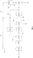
- Fig. 1 shows a process according to a mode of implementing the invention based on an oxygen autothermal reformer ATR and pre-reformer.
- Fig. 1 denote the following systems or apparatus:
- a charge 10 comprising natural gas and steam is preheated in AUX and converted into a synthesis gas 11 via the reformers PRE and ATR.
- the autothermal reformer ATR operates with a flow 22 of enriched air or oxygen.
- the synthesis gas which contains H2, CO and CO2, undergoes a shift reaction in SHF and then removal of CO2 in CDR.
- the section SHF may comprise shift treatments at different temperatures.
- the section CDR operates for example with chemical/physical washing of the gas using an aqueous amine solution.
- the section CDR produces a CO2-depleted syngas 12 and a flow 13 of CO2 which may be sequestered or used for other process purposes, for example in order to produce urea.
- the synthesis gas 12 has the following composition: 98% H2, 1% CO+CH4, 0.1% CO2, Ar+N2 0.9%.
- a part 14 of said CO2-depleted syngas 12 is used as fuel in a furnace in the front end, for example in a charge heater (AUX block).
- the remaining part 18 of synthesis gas is further treated in the methanator MET.
- the fuel fraction 14 of synthesis gas together with a tail gas 15 of the HRU section, feeds one or more users of the block AUX via the fuel line 16.
- a suitable quantity of natural gas 17 is added to the gas 16.
- Nitrogen 19 from the air separation section ASU is added to the process fraction 18 of the synthesis gas, after it has passed inside the methanator (optional).
- the gas thus obtained together with a flow of hydrogen 20 recovered from the HRU section, feeds the synthesis section SYN.
- Said synthesis section produces ammonia 23 and a flow 21 of purging gas treated in the section HRU for recovery of the hydrogen contained inside it.
- the separation section ASU produces, in addition to the nitrogen 19, also the flow 22 of enriched air or oxygen for the autothermal reformer ATR.
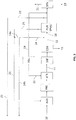
- Fig. 2 shows a process according to a preferred mode of implementing the invention based on primary reforming and ATR.
- the block SMR in Fig, 1 denotes the primary reformer (or steam reformer) plus auxiliary apparatus, for example steam generators.
- auxiliary apparatus for example steam generators.
- the remaining symbols in Fig. 2 correspond to the symbols in Fig. 1 and therefore the description is not repeated.
- Fig. 2 also shows an optional line 15a for recycling part of the tail gas 15 from the unit HRU for feeding the primary reformer SMR.
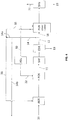
- Fig. 3 shows an ATR-based process, similar to Fig. 1 , but comprising a purification of the process fraction of the synthesis gas in a section PUR, which in this example comprises a PSA unit.
- the fuel fraction 14 separated from the CO2-depleted synthesis gas 12 is divided into a first portion 14a used as fuel in a furnace in the front end, for example in the block AUX, and a second portion 14b exported as excess fuel.
- the remaining part 18 of synthesis gas is further treated in the PSA unit.
- a portion 23 of the effluent of the PSA unit is (optionally) exported as excess fuel. Said portion 23 has a greater hydrogen purity than the gas portion 14b.
- Fig. 4 shows a process based on POX, comprising purification of the process fraction of the synthesis gas in a section PUR comprising dryer and LNW (liquid nitrogen wash).
- the fuel fraction 14 separated from the CO2-depleted synthesis gas 12 is split into a first portion 14a used as fuel for example in the block AUX, and a second portion 14b exported as excess fuel.
- Said portion 14a together with a tail gas 35 of the section PUR, feeds one or more users of the block AUX via the fuel line 36.
- Said tail gas 35 results from the combination of the tail gas of the LNW and of the dryer.
- the process according to the invention allows to produce ammonia with emissions of CO2 of about 0.1 t/t compared to about 0.7 t/t in the prior art.
- Table 1 refers to a plant with a capacity of 3000 metric tonnes per day (MTD) of ammonia produced.
- Table 1 compares the following options:
- the table shows that the process according to the invention (option 3) requires a front end suitable for producing also the gas fraction to be used as fuel in the furnaces; in fact the quantity of CO2 captured in the process amounts to 5200 MTD compared to 3600 for options (1) and (2), and the synthesis gas flowrate in the front end is about 20% more than Fig. 1 and 2 . Despite this, the consumption of the plant is much less than that of option (2) (7.0 instead of 7.4 Gcal/MT) and is competitive with the plant without capturing according to option (1). The total duty of the furnaces is only 75% of option (1).
- option (4) the energy consumption obtained is less than in option (3), i.e. equal to 6.9 Gcal/MT, and also the cost of the plant is less.
- the quantity of CO2 separated in the process is less than in option (3); the duty of the furnaces is greater than in (3), but is comparable with that of options (1) and (2); the oxygen consumption is markedly less than (3); the flowrate in the front end is markedly less than (3) and comparable with (1) and (2).
- the example also shows the advantage of modifying a plant operating as per option (1), preferably implementing option (4).
- option (4) the duty of the furnaces and the flowrate of the gases remain substantially unvaried, while the CO2 emissions are reduced.
- the invention thus achieves the object of minimizing the CO2 emissions of a conventional plant without losing ammonia production.
- Table 2 refers to a plant with a capacity of 3000 metric tonnes per day (MTD) of ammonia produced, which is self-sufficient from the point of view of the steam and electric power.
- the process comprises the consumption relating to the compression of the CO2 sequestered up to the pressure of 100 bar.
- the natural gas consumption and the CO2 emissions indicated also consider the superheated steam production in AUX for driving all the turbines, and the production of the electric power necessary for the process.
- the above example shows how the invention is able to achieve extremely low CO2 emission levels, corresponding to almost total capture (>98%), while maintaining competitive energy consumption levels.
Claims (14)
- Procédé pour la synthèse d'ammoniac à partir de gaz naturel, comprenant :la conversion d'une charge de gaz naturel désulfuré et de vapeur, avec de l'air enrichi en oxygène ou avec de l'oxygène, en un gaz de synthèse (11) contenant de l'hydrogène, du CO et du CO2, dans une section de conversion ;un traitement dudit gaz de synthèse (11), comprenant au moins une réaction de conversion du monoxyde de carbone en CO2, et une séparation subséquente du CO2 à partir du gaz, ce qui donne ainsi un gaz de synthèse appauvri en CO2 (12) et un courant gazeux riche en CO2 contenant le CO2 séparé du gaz ;éventuellement une étape pour la méthanation du gaz de synthèse et/ou l'addition d'azote au gaz de synthèse,caractérisé par :
la séparation d'une partie (14) dudit gaz de synthèse appauvri en CO2 (12) sous forme de fraction combustible, où ladite fraction combustible (14) est introduite en tant que combustible dans au moins un four, et où ladite séparation de la fraction combustible comprend la division dudit gaz de synthèse appauvri en CO2 en au moins un premier courant et un deuxième courant, lesdits courants ayant la même composition, où le premier courant forme la fraction combustible et le deuxième courant est un gaz de procédé destiné à la synthèse d'ammoniac éventuellement après purification supplémentaire. - Procédé selon la revendication 1, dans lequel ladite fraction combustible (14) représente entre 1 % et 40 %, de préférence entre 10 % et 30 %, de la quantité totale dudit gaz de synthèse appauvri en CO2 (12).
- Procédé selon l'une quelconque des revendications précédentes, dans lequel ladite fraction combustible est séparée en amont de l'étape de méthanation ou en amont de l'étape d'addition d'azote.
- Procédé selon l'une quelconque des revendications précédentes, dans lequel ledit gaz de synthèse appauvri en CO2 (12) ne contient pas plus de 1000 ppm en volume de CO2.
- Procédé selon l'une quelconque des revendications précédentes, dans lequel ledit air enrichi contient au moins 50 % d'oxygène, de préférence au moins 90 % d'oxygène.
- Procédé selon l'une quelconque des revendications précédentes, dans lequel ladite fraction combustible (14) du gaz de synthèse alimente un ou plusieurs des appareils suivants : un four surchauffeur et/ou de production de vapeur ; un ou plusieurs brûleurs d'un vaporeformeur primaire ; un ou plusieurs fours pour préchauffer la charge d'un reformeur adiabatique ou d'un réacteur d'oxydation partielle ou d'une section de désulfuration de gaz naturel.
- Procédé selon l'une quelconque des revendications précédentes, dans lequel : un gaz de purge (21) du procédé de synthèse d'ammoniac, contenant de l'hydrogène et du méthane, est traité de façon que l'hydrogène qu'il contient soit récupéré, ce qui donne un gaz riche en hydrogène (20) et un gaz de queue (15) contenant du méthane ; au moins une partie (15a) dudit gaz de queue (15) est recyclée en tant que gaz de procédé et soumise à ladite étape de conversion du gaz naturel en gaz de synthèse.
- Procédé selon l'une quelconque des revendications précédentes, dans lequel : une partie dudit gaz de synthèse appauvri en CO2 (12) est traitée dans une unité de séparation d'azote, ce qui donne un premier courant de gaz de synthèse appauvri en azote et un deuxième courant enrichi en azote ; au moins une partie dudit premier courant, de préférence la totalité de celui-ci, est utilisée en tant que combustible ; toute partie restante dudit premier courant est introduite dans la synthèse d'ammoniac conjointement avec le deuxième courant.
- Procédé selon l'une quelconque des revendications précédentes, comprenant aussi une étape d'expansion, avec production de travail mécanique, du gaz de synthèse appauvri en CO2 (12), éventuellement après son chauffage.
- Procédé selon l'une quelconque des revendications précédentes, dans lequel le rapport global vapeur/carbone dans l'étape de conversion est supérieur à 2,0, de préférence supérieur à 2,4 et plus préférablement supérieur à 2,7.
- Procédé selon l'une quelconque des revendications précédentes, dans lequelladite fraction combustible de gaz de synthèse (14) forme la totalité du combustible des fours utilisés dans la section de conversion, ouune quantité de gaz naturel sert de combustible de correction, ledit combustible de correction ne représentant pas plus de 15 % de la chaleur de combustion totale.
- Procédé selon l'une quelconque des revendications précédentes, dans lequel :la fraction combustible est produite en excès par rapport au combustible nécessaire pour la section de conversion, la quantité de ladite fraction combustible dépassant celle requise étant exportée depuis le procédé, etla régulation de la section de conversion est effectuée par modulation de la quantité de ladite fraction combustible dirigée vers la section de conversion et de la quantité exportée depuis le procédé.
- Procédé selon l'une quelconque des revendications précédentes, dans lequel :la conversion de la charge de gaz naturel en gaz de synthèse comprend une étape de reformage adiabatique, éventuellement avec pré-reformage, ou une étape d'oxydation partielle ;ladite étape de reformage adiabatique ou d'oxydation partielle est effectuée avec un rapport vapeur/carbone non supérieur à 2.
- Procédé selon l'une quelconque des revendications précédentes, dans lequel la conversion du gaz naturel en gaz de synthèse comprend : un reformage primaire du gaz naturel en présence de vapeur et un reformage secondaire effectué avec ledit courant d'oxygène ou ledit air enrichi.
Applications Claiming Priority (3)
| Application Number | Priority Date | Filing Date | Title |
|---|---|---|---|
| EP17156256 | 2017-02-15 | ||
| EP17195305.2A EP3363770A1 (fr) | 2017-02-15 | 2017-10-06 | Procédé desynthèse d'ammoniac ayant de faibles émissions de co2 dans l'atmosphère |
| PCT/EP2018/052358 WO2018149641A1 (fr) | 2017-02-15 | 2018-01-31 | Procédé de synthèse d'ammoniac avec de faibles émissions de co2 dans l'atmosphère |
Publications (2)
| Publication Number | Publication Date |
|---|---|
| EP3583067A1 EP3583067A1 (fr) | 2019-12-25 |
| EP3583067B1 true EP3583067B1 (fr) | 2021-09-08 |
Family
ID=58410072
Family Applications (2)
| Application Number | Title | Priority Date | Filing Date |
|---|---|---|---|
| EP17195305.2A Withdrawn EP3363770A1 (fr) | 2017-02-15 | 2017-10-06 | Procédé desynthèse d'ammoniac ayant de faibles émissions de co2 dans l'atmosphère |
| EP18702977.2A Active EP3583067B1 (fr) | 2017-02-15 | 2018-01-31 | Procédé de synthèse d'ammoniac avec de faibles émissions de co2 dans l'atmosphère |
Family Applications Before (1)
| Application Number | Title | Priority Date | Filing Date |
|---|---|---|---|
| EP17195305.2A Withdrawn EP3363770A1 (fr) | 2017-02-15 | 2017-10-06 | Procédé desynthèse d'ammoniac ayant de faibles émissions de co2 dans l'atmosphère |
Country Status (11)
| Country | Link |
|---|---|
| US (1) | US11286168B2 (fr) |
| EP (2) | EP3363770A1 (fr) |
| CN (1) | CN110352175B (fr) |
| AU (1) | AU2018221479B2 (fr) |
| BR (1) | BR112019016817A2 (fr) |
| CA (1) | CA3049733A1 (fr) |
| MY (1) | MY191615A (fr) |
| RU (1) | RU2759379C2 (fr) |
| SA (1) | SA519402257B1 (fr) |
| UA (1) | UA127541C2 (fr) |
| WO (1) | WO2018149641A1 (fr) |
Cited By (1)
| Publication number | Priority date | Publication date | Assignee | Title |
|---|---|---|---|---|
| EP4342845A1 (fr) | 2022-09-26 | 2024-03-27 | L'air Liquide, Societe Anonyme Pour L'etude Et L'exploitation Des Procedes Georges Claude | Procédé et installation pour la production d'un flux de gaz de synthèse riche en hydrogène à partir d'un flux de gaz d'entrée contenant du carbone |
Families Citing this family (9)
| Publication number | Priority date | Publication date | Assignee | Title |
|---|---|---|---|---|
| EP3896031A1 (fr) * | 2020-04-17 | 2021-10-20 | Casale Sa | Modernisation d'une installation d'ammoniac-urée |
| GB202009970D0 (en) * | 2020-06-30 | 2020-08-12 | Johnson Matthey Plc | Low-carbon hydrogen process |
| US20230271829A1 (en) | 2020-08-17 | 2023-08-31 | Topsoe A/S | ATR-Based Hydrogen Process and Plant |
| US20230294985A1 (en) | 2020-08-17 | 2023-09-21 | Topsoe A/S | Low carbon hydrogen fuel |
| CA3217663A1 (fr) | 2021-04-28 | 2022-11-03 | Topsoe A/S | Procede de production d'ammoniac bleu |
| GB202201332D0 (en) * | 2022-02-02 | 2022-03-16 | Johnson Matthey Plc | Low-carbon hydrogen process |
| WO2023170389A1 (fr) * | 2022-03-11 | 2023-09-14 | Johnson Matthey Public Limited Company | Procédé de production d'hydrogène et méthode de modernisation d'une unité de production d'hydrogène |
| GB202204042D0 (en) * | 2022-03-23 | 2022-05-04 | Johnson Matthey Plc | Process for producing hydrogen and method of retrofitting a hydrogen production unit |
| WO2023213862A1 (fr) | 2022-05-05 | 2023-11-09 | Topsoe A/S | Procédé de production d'ammoniac bleu |
Citations (6)
| Publication number | Priority date | Publication date | Assignee | Title |
|---|---|---|---|---|
| US20040234426A1 (en) | 2001-06-28 | 2004-11-25 | Satish Reddy | Improved ammonia plant configuration and methods |
| EP1648817B1 (fr) | 2003-07-28 | 2006-10-25 | Uhde GmbH | Procede pour produire de l'hydrogene a partir d'un gaz contenant du methane, en particulier a partir de gaz naturel, et dispositif pour la mise en oeuvre de ce procede |
| EP2266922A1 (fr) | 2009-06-03 | 2010-12-29 | Air Products and Chemicals, Inc. | Reformage de vapeur d'hydrocarbures avec émissions réduites de dioxyde de carbone |
| DE102014209635A1 (de) | 2014-05-21 | 2015-11-26 | Thyssenkrupp Ag | Herstellung von Synthesegas mit zwei autothermen Reformern |
| DE102015210803A1 (de) | 2015-06-12 | 2016-12-15 | Thyssenkrupp Ag | Festlegung von Druck, Temperatur und S/C-Verhältnis für einen rußfreien ATR-Betrieb |
| EP2817260B1 (fr) | 2012-02-24 | 2018-05-16 | Casale SA | Procédé de production de gaz de synthèse d'ammoniac |
Family Cites Families (10)
| Publication number | Priority date | Publication date | Assignee | Title |
|---|---|---|---|---|
| SU594048A1 (ru) * | 1976-06-10 | 1978-02-25 | Pritula Mikhail Ya | Способ получени амиака |
| US20100037521A1 (en) * | 2008-08-13 | 2010-02-18 | L'Air Liquide Societe Anonyme Pour L'Etude et l'Exploitatation Des Procedes Georges Claude | Novel Steam Reformer Based Hydrogen Plant Scheme for Enhanced Carbon Dioxide Recovery |
| EP2284125A1 (fr) * | 2009-08-13 | 2011-02-16 | Ammonia Casale S.A. | Procédé de remaniement d'une d'installation de fabrication d'ammoniac avec lavage à base d'azote d'un flux de purge |
| WO2011150253A1 (fr) * | 2010-05-26 | 2011-12-01 | Gtlpetrol Llc | Production d'ammoniac en utilisant de l'hydrogène haute pression ultra-pur |
| CN102381717B (zh) * | 2010-09-01 | 2013-07-31 | 中国石油天然气股份有限公司 | 一种天然气转化生产氨的方法 |
| CN102502702A (zh) * | 2011-09-27 | 2012-06-20 | 中国石油天然气股份有限公司 | 以天然气为原料制备氨的方法 |
| CN102533365B (zh) * | 2011-12-12 | 2014-07-30 | 航天长征化学工程股份有限公司 | 一种液化天然气及合成氨联产工艺 |
| EP2801550A1 (fr) * | 2013-05-10 | 2014-11-12 | Ammonia Casale S.A. | Procédé de production d'un gaz de synthèse d'ammoniac avec décalage de température élevé et faible rapport vapeur-carbone |
| CN103303863A (zh) * | 2013-06-13 | 2013-09-18 | 黄家鹄 | 由焦炉气制取氨合成气的方法 |
| US9458099B2 (en) * | 2013-07-25 | 2016-10-04 | Thermoselect Aktiengesellschaft | Method of manufacturing urea from refuse, preferably domestic waste, of any composition |
-
2017
- 2017-10-06 EP EP17195305.2A patent/EP3363770A1/fr not_active Withdrawn
-
2018
- 2018-01-31 RU RU2019128252A patent/RU2759379C2/ru active
- 2018-01-31 US US16/485,695 patent/US11286168B2/en active Active
- 2018-01-31 BR BR112019016817A patent/BR112019016817A2/pt unknown
- 2018-01-31 AU AU2018221479A patent/AU2018221479B2/en active Active
- 2018-01-31 WO PCT/EP2018/052358 patent/WO2018149641A1/fr unknown
- 2018-01-31 CA CA3049733A patent/CA3049733A1/fr active Pending
- 2018-01-31 MY MYPI2019004560A patent/MY191615A/en unknown
- 2018-01-31 UA UAA201909719A patent/UA127541C2/uk unknown
- 2018-01-31 EP EP18702977.2A patent/EP3583067B1/fr active Active
- 2018-01-31 CN CN201880011937.5A patent/CN110352175B/zh active Active
-
2019
- 2019-07-18 SA SA519402257A patent/SA519402257B1/ar unknown
Patent Citations (7)
| Publication number | Priority date | Publication date | Assignee | Title |
|---|---|---|---|---|
| US20040234426A1 (en) | 2001-06-28 | 2004-11-25 | Satish Reddy | Improved ammonia plant configuration and methods |
| EP1648817B1 (fr) | 2003-07-28 | 2006-10-25 | Uhde GmbH | Procede pour produire de l'hydrogene a partir d'un gaz contenant du methane, en particulier a partir de gaz naturel, et dispositif pour la mise en oeuvre de ce procede |
| EP2266922A1 (fr) | 2009-06-03 | 2010-12-29 | Air Products and Chemicals, Inc. | Reformage de vapeur d'hydrocarbures avec émissions réduites de dioxyde de carbone |
| US8137422B2 (en) | 2009-06-03 | 2012-03-20 | Air Products And Chemicals, Inc. | Steam-hydrocarbon reforming with reduced carbon dioxide emissions |
| EP2817260B1 (fr) | 2012-02-24 | 2018-05-16 | Casale SA | Procédé de production de gaz de synthèse d'ammoniac |
| DE102014209635A1 (de) | 2014-05-21 | 2015-11-26 | Thyssenkrupp Ag | Herstellung von Synthesegas mit zwei autothermen Reformern |
| DE102015210803A1 (de) | 2015-06-12 | 2016-12-15 | Thyssenkrupp Ag | Festlegung von Druck, Temperatur und S/C-Verhältnis für einen rußfreien ATR-Betrieb |
Non-Patent Citations (4)
| Title |
|---|
| ANONYMOUS: "MaxAppl Ammonia Principles and Industrial Practice", WILEY-VCH, 1999, pages 1 - 305, XP055932846 |
| DR. KLAUS NOELKER , JOHANNING DR JOACHIM: "Autothermal reforming: a flexible syngas route with future potentiol", 2010, pages 1 - 20, XP055933128 |
| HÄUSSINGER PETER, LOHMÜLLER REINER, WATSON ALLAN M.: "Hydrogen, 3. Purification", ULLMANN'S ENCYCLOPEDIA OF INDUSTRIAL CHEMISTRY, vol. 18, 2011, pages 309 - 333, XP055070696 |
| RYOTA SHIMURA: "Ureo Product Expansion by Newly Developed C02 Recovery Process from Primary Reformer Flue Gas", AICHE TECHNICAL MANULA, vol. 47, 2006, pages 237 - 246, XP055933133 |
Cited By (1)
| Publication number | Priority date | Publication date | Assignee | Title |
|---|---|---|---|---|
| EP4342845A1 (fr) | 2022-09-26 | 2024-03-27 | L'air Liquide, Societe Anonyme Pour L'etude Et L'exploitation Des Procedes Georges Claude | Procédé et installation pour la production d'un flux de gaz de synthèse riche en hydrogène à partir d'un flux de gaz d'entrée contenant du carbone |
Also Published As
| Publication number | Publication date |
|---|---|
| EP3363770A1 (fr) | 2018-08-22 |
| CN110352175B (zh) | 2022-12-09 |
| US11286168B2 (en) | 2022-03-29 |
| RU2759379C2 (ru) | 2021-11-12 |
| AU2018221479B2 (en) | 2023-06-22 |
| CA3049733A1 (fr) | 2018-08-23 |
| MY191615A (en) | 2022-07-03 |
| WO2018149641A1 (fr) | 2018-08-23 |
| UA127541C2 (uk) | 2023-10-04 |
| RU2019128252A3 (fr) | 2021-03-16 |
| CN110352175A (zh) | 2019-10-18 |
| AU2018221479A1 (en) | 2019-08-01 |
| SA519402257B1 (ar) | 2022-11-22 |
| US20200055738A1 (en) | 2020-02-20 |
| EP3583067A1 (fr) | 2019-12-25 |
| BR112019016817A2 (pt) | 2020-04-07 |
| RU2019128252A (ru) | 2021-03-16 |
Similar Documents
| Publication | Publication Date | Title |
|---|---|---|
| EP3583067B1 (fr) | Procédé de synthèse d'ammoniac avec de faibles émissions de co2 dans l'atmosphère | |
| US11891950B2 (en) | Systems and methods for power production with integrated production of hydrogen | |
| EP3658491B1 (fr) | Procédé de préparation de gaz de synthese d'ammoniac | |
| US20230271829A1 (en) | ATR-Based Hydrogen Process and Plant | |
| US11565937B2 (en) | Process for producing a hydrogen-containing synthesis gas | |
| CN116761774A (zh) | 用于制备合成气的方法 |
Legal Events
| Date | Code | Title | Description |
|---|---|---|---|
| STAA | Information on the status of an ep patent application or granted ep patent |
Free format text: STATUS: UNKNOWN |
|
| STAA | Information on the status of an ep patent application or granted ep patent |
Free format text: STATUS: THE INTERNATIONAL PUBLICATION HAS BEEN MADE |
|
| PUAI | Public reference made under article 153(3) epc to a published international application that has entered the european phase |
Free format text: ORIGINAL CODE: 0009012 |
|
| STAA | Information on the status of an ep patent application or granted ep patent |
Free format text: STATUS: REQUEST FOR EXAMINATION WAS MADE |
|
| 17P | Request for examination filed |
Effective date: 20190719 |
|
| AK | Designated contracting states |
Kind code of ref document: A1 Designated state(s): AL AT BE BG CH CY CZ DE DK EE ES FI FR GB GR HR HU IE IS IT LI LT LU LV MC MK MT NL NO PL PT RO RS SE SI SK SM TR |
|
| AX | Request for extension of the european patent |
Extension state: BA ME |
|
| DAV | Request for validation of the european patent (deleted) | ||
| DAX | Request for extension of the european patent (deleted) | ||
| STAA | Information on the status of an ep patent application or granted ep patent |
Free format text: STATUS: EXAMINATION IS IN PROGRESS |
|
| STAA | Information on the status of an ep patent application or granted ep patent |
Free format text: STATUS: EXAMINATION IS IN PROGRESS |
|
| 17Q | First examination report despatched |
Effective date: 20201028 |
|
| GRAP | Despatch of communication of intention to grant a patent |
Free format text: ORIGINAL CODE: EPIDOSNIGR1 |
|
| STAA | Information on the status of an ep patent application or granted ep patent |
Free format text: STATUS: GRANT OF PATENT IS INTENDED |
|
| INTG | Intention to grant announced |
Effective date: 20210615 |
|
| GRAS | Grant fee paid |
Free format text: ORIGINAL CODE: EPIDOSNIGR3 |
|
| GRAA | (expected) grant |
Free format text: ORIGINAL CODE: 0009210 |
|
| STAA | Information on the status of an ep patent application or granted ep patent |
Free format text: STATUS: THE PATENT HAS BEEN GRANTED |
|
| AK | Designated contracting states |
Kind code of ref document: B1 Designated state(s): AL AT BE BG CH CY CZ DE DK EE ES FI FR GB GR HR HU IE IS IT LI LT LU LV MC MK MT NL NO PL PT RO RS SE SI SK SM TR |
|
| REG | Reference to a national code |
Ref country code: GB Ref legal event code: FG4D |
|
| REG | Reference to a national code |
Ref country code: CH Ref legal event code: EP Ref country code: AT Ref legal event code: REF Ref document number: 1428444 Country of ref document: AT Kind code of ref document: T Effective date: 20210915 |
|
| REG | Reference to a national code |
Ref country code: DE Ref legal event code: R096 Ref document number: 602018023204 Country of ref document: DE |
|
| REG | Reference to a national code |
Ref country code: IE Ref legal event code: FG4D |
|
| REG | Reference to a national code |
Ref country code: LT Ref legal event code: MG9D |
|
| REG | Reference to a national code |
Ref country code: NL Ref legal event code: MP Effective date: 20210908 |
|
| PG25 | Lapsed in a contracting state [announced via postgrant information from national office to epo] |
Ref country code: NO Free format text: LAPSE BECAUSE OF FAILURE TO SUBMIT A TRANSLATION OF THE DESCRIPTION OR TO PAY THE FEE WITHIN THE PRESCRIBED TIME-LIMIT Effective date: 20211208 Ref country code: BG Free format text: LAPSE BECAUSE OF FAILURE TO SUBMIT A TRANSLATION OF THE DESCRIPTION OR TO PAY THE FEE WITHIN THE PRESCRIBED TIME-LIMIT Effective date: 20211208 Ref country code: LT Free format text: LAPSE BECAUSE OF FAILURE TO SUBMIT A TRANSLATION OF THE DESCRIPTION OR TO PAY THE FEE WITHIN THE PRESCRIBED TIME-LIMIT Effective date: 20210908 Ref country code: SE Free format text: LAPSE BECAUSE OF FAILURE TO SUBMIT A TRANSLATION OF THE DESCRIPTION OR TO PAY THE FEE WITHIN THE PRESCRIBED TIME-LIMIT Effective date: 20210908 Ref country code: RS Free format text: LAPSE BECAUSE OF FAILURE TO SUBMIT A TRANSLATION OF THE DESCRIPTION OR TO PAY THE FEE WITHIN THE PRESCRIBED TIME-LIMIT Effective date: 20210908 Ref country code: HR Free format text: LAPSE BECAUSE OF FAILURE TO SUBMIT A TRANSLATION OF THE DESCRIPTION OR TO PAY THE FEE WITHIN THE PRESCRIBED TIME-LIMIT Effective date: 20210908 Ref country code: ES Free format text: LAPSE BECAUSE OF FAILURE TO SUBMIT A TRANSLATION OF THE DESCRIPTION OR TO PAY THE FEE WITHIN THE PRESCRIBED TIME-LIMIT Effective date: 20210908 Ref country code: FI Free format text: LAPSE BECAUSE OF FAILURE TO SUBMIT A TRANSLATION OF THE DESCRIPTION OR TO PAY THE FEE WITHIN THE PRESCRIBED TIME-LIMIT Effective date: 20210908 |
|
| REG | Reference to a national code |
Ref country code: AT Ref legal event code: MK05 Ref document number: 1428444 Country of ref document: AT Kind code of ref document: T Effective date: 20210908 |
|
| PG25 | Lapsed in a contracting state [announced via postgrant information from national office to epo] |
Ref country code: LV Free format text: LAPSE BECAUSE OF FAILURE TO SUBMIT A TRANSLATION OF THE DESCRIPTION OR TO PAY THE FEE WITHIN THE PRESCRIBED TIME-LIMIT Effective date: 20210908 Ref country code: GR Free format text: LAPSE BECAUSE OF FAILURE TO SUBMIT A TRANSLATION OF THE DESCRIPTION OR TO PAY THE FEE WITHIN THE PRESCRIBED TIME-LIMIT Effective date: 20211209 |
|
| PG25 | Lapsed in a contracting state [announced via postgrant information from national office to epo] |
Ref country code: AT Free format text: LAPSE BECAUSE OF FAILURE TO SUBMIT A TRANSLATION OF THE DESCRIPTION OR TO PAY THE FEE WITHIN THE PRESCRIBED TIME-LIMIT Effective date: 20210908 |
|
| PG25 | Lapsed in a contracting state [announced via postgrant information from national office to epo] |
Ref country code: IS Free format text: LAPSE BECAUSE OF FAILURE TO SUBMIT A TRANSLATION OF THE DESCRIPTION OR TO PAY THE FEE WITHIN THE PRESCRIBED TIME-LIMIT Effective date: 20220108 Ref country code: SM Free format text: LAPSE BECAUSE OF FAILURE TO SUBMIT A TRANSLATION OF THE DESCRIPTION OR TO PAY THE FEE WITHIN THE PRESCRIBED TIME-LIMIT Effective date: 20210908 Ref country code: SK Free format text: LAPSE BECAUSE OF FAILURE TO SUBMIT A TRANSLATION OF THE DESCRIPTION OR TO PAY THE FEE WITHIN THE PRESCRIBED TIME-LIMIT Effective date: 20210908 Ref country code: RO Free format text: LAPSE BECAUSE OF FAILURE TO SUBMIT A TRANSLATION OF THE DESCRIPTION OR TO PAY THE FEE WITHIN THE PRESCRIBED TIME-LIMIT Effective date: 20210908 Ref country code: PT Free format text: LAPSE BECAUSE OF FAILURE TO SUBMIT A TRANSLATION OF THE DESCRIPTION OR TO PAY THE FEE WITHIN THE PRESCRIBED TIME-LIMIT Effective date: 20220110 Ref country code: PL Free format text: LAPSE BECAUSE OF FAILURE TO SUBMIT A TRANSLATION OF THE DESCRIPTION OR TO PAY THE FEE WITHIN THE PRESCRIBED TIME-LIMIT Effective date: 20210908 Ref country code: NL Free format text: LAPSE BECAUSE OF FAILURE TO SUBMIT A TRANSLATION OF THE DESCRIPTION OR TO PAY THE FEE WITHIN THE PRESCRIBED TIME-LIMIT Effective date: 20210908 Ref country code: EE Free format text: LAPSE BECAUSE OF FAILURE TO SUBMIT A TRANSLATION OF THE DESCRIPTION OR TO PAY THE FEE WITHIN THE PRESCRIBED TIME-LIMIT Effective date: 20210908 Ref country code: CZ Free format text: LAPSE BECAUSE OF FAILURE TO SUBMIT A TRANSLATION OF THE DESCRIPTION OR TO PAY THE FEE WITHIN THE PRESCRIBED TIME-LIMIT Effective date: 20210908 Ref country code: AL Free format text: LAPSE BECAUSE OF FAILURE TO SUBMIT A TRANSLATION OF THE DESCRIPTION OR TO PAY THE FEE WITHIN THE PRESCRIBED TIME-LIMIT Effective date: 20210908 |
|
| REG | Reference to a national code |
Ref country code: DE Ref legal event code: R026 Ref document number: 602018023204 Country of ref document: DE |
|
| PLBI | Opposition filed |
Free format text: ORIGINAL CODE: 0009260 |
|
| PLAB | Opposition data, opponent's data or that of the opponent's representative modified |
Free format text: ORIGINAL CODE: 0009299OPPO |
|
| PLAX | Notice of opposition and request to file observation + time limit sent |
Free format text: ORIGINAL CODE: EPIDOSNOBS2 |
|
| 26 | Opposition filed |
Opponent name: THYSSENKRUPP INDUSTRIAL SOLUTIONS AG Effective date: 20220608 Opponent name: LINDE AG Effective date: 20220608 |
|
| R26 | Opposition filed (corrected) |
Opponent name: THYSSENKRUPP INDUSTRIAL SOLUTIONS AG Effective date: 20220608 Opponent name: LINDE AG Effective date: 20220608 |
|
| PG25 | Lapsed in a contracting state [announced via postgrant information from national office to epo] |
Ref country code: DK Free format text: LAPSE BECAUSE OF FAILURE TO SUBMIT A TRANSLATION OF THE DESCRIPTION OR TO PAY THE FEE WITHIN THE PRESCRIBED TIME-LIMIT Effective date: 20210908 |
|
| PG25 | Lapsed in a contracting state [announced via postgrant information from national office to epo] |
Ref country code: SI Free format text: LAPSE BECAUSE OF FAILURE TO SUBMIT A TRANSLATION OF THE DESCRIPTION OR TO PAY THE FEE WITHIN THE PRESCRIBED TIME-LIMIT Effective date: 20210908 Ref country code: MC Free format text: LAPSE BECAUSE OF FAILURE TO SUBMIT A TRANSLATION OF THE DESCRIPTION OR TO PAY THE FEE WITHIN THE PRESCRIBED TIME-LIMIT Effective date: 20210908 |
|
| REG | Reference to a national code |
Ref country code: CH Ref legal event code: PL |
|
| REG | Reference to a national code |
Ref country code: BE Ref legal event code: MM Effective date: 20220131 |
|
| PG25 | Lapsed in a contracting state [announced via postgrant information from national office to epo] |
Ref country code: LU Free format text: LAPSE BECAUSE OF NON-PAYMENT OF DUE FEES Effective date: 20220131 |
|
| PLBB | Reply of patent proprietor to notice(s) of opposition received |
Free format text: ORIGINAL CODE: EPIDOSNOBS3 |
|
| PG25 | Lapsed in a contracting state [announced via postgrant information from national office to epo] |
Ref country code: BE Free format text: LAPSE BECAUSE OF NON-PAYMENT OF DUE FEES Effective date: 20220131 |
|
| PG25 | Lapsed in a contracting state [announced via postgrant information from national office to epo] |
Ref country code: LI Free format text: LAPSE BECAUSE OF NON-PAYMENT OF DUE FEES Effective date: 20220131 Ref country code: CH Free format text: LAPSE BECAUSE OF NON-PAYMENT OF DUE FEES Effective date: 20220131 |
|
| PG25 | Lapsed in a contracting state [announced via postgrant information from national office to epo] |
Ref country code: IT Free format text: LAPSE BECAUSE OF FAILURE TO SUBMIT A TRANSLATION OF THE DESCRIPTION OR TO PAY THE FEE WITHIN THE PRESCRIBED TIME-LIMIT Effective date: 20210908 Ref country code: IE Free format text: LAPSE BECAUSE OF NON-PAYMENT OF DUE FEES Effective date: 20220131 |
|
| PGFP | Annual fee paid to national office [announced via postgrant information from national office to epo] |
Ref country code: DE Payment date: 20221220 Year of fee payment: 6 |
|
| P01 | Opt-out of the competence of the unified patent court (upc) registered |
Effective date: 20230527 |
|
| PGFP | Annual fee paid to national office [announced via postgrant information from national office to epo] |
Ref country code: GB Payment date: 20231219 Year of fee payment: 7 |
|
| PGFP | Annual fee paid to national office [announced via postgrant information from national office to epo] |
Ref country code: FR Payment date: 20231219 Year of fee payment: 7 |