EP3582991B1 - Scherenstromabnehmer und schienenfahrzeug mit solch einem scherenstromabnehmer - Google Patents
Scherenstromabnehmer und schienenfahrzeug mit solch einem scherenstromabnehmer Download PDFInfo
- Publication number
- EP3582991B1 EP3582991B1 EP18706812.7A EP18706812A EP3582991B1 EP 3582991 B1 EP3582991 B1 EP 3582991B1 EP 18706812 A EP18706812 A EP 18706812A EP 3582991 B1 EP3582991 B1 EP 3582991B1
- Authority
- EP
- European Patent Office
- Prior art keywords
- angle
- aileron
- pantograph
- control member
- variation
- Prior art date
- Legal status (The legal status is an assumption and is not a legal conclusion. Google has not performed a legal analysis and makes no representation as to the accuracy of the status listed.)
- Active
Links
Images





Classifications
-
- B—PERFORMING OPERATIONS; TRANSPORTING
- B60—VEHICLES IN GENERAL
- B60L—PROPULSION OF ELECTRICALLY-PROPELLED VEHICLES; SUPPLYING ELECTRIC POWER FOR AUXILIARY EQUIPMENT OF ELECTRICALLY-PROPELLED VEHICLES; ELECTRODYNAMIC BRAKE SYSTEMS FOR VEHICLES IN GENERAL; MAGNETIC SUSPENSION OR LEVITATION FOR VEHICLES; MONITORING OPERATING VARIABLES OF ELECTRICALLY-PROPELLED VEHICLES; ELECTRIC SAFETY DEVICES FOR ELECTRICALLY-PROPELLED VEHICLES
- B60L5/00—Current collectors for power supply lines of electrically-propelled vehicles
- B60L5/18—Current collectors for power supply lines of electrically-propelled vehicles using bow-type collectors in contact with trolley wire
- B60L5/22—Supporting means for the contact bow
-
- B—PERFORMING OPERATIONS; TRANSPORTING
- B60—VEHICLES IN GENERAL
- B60L—PROPULSION OF ELECTRICALLY-PROPELLED VEHICLES; SUPPLYING ELECTRIC POWER FOR AUXILIARY EQUIPMENT OF ELECTRICALLY-PROPELLED VEHICLES; ELECTRODYNAMIC BRAKE SYSTEMS FOR VEHICLES IN GENERAL; MAGNETIC SUSPENSION OR LEVITATION FOR VEHICLES; MONITORING OPERATING VARIABLES OF ELECTRICALLY-PROPELLED VEHICLES; ELECTRIC SAFETY DEVICES FOR ELECTRICALLY-PROPELLED VEHICLES
- B60L5/00—Current collectors for power supply lines of electrically-propelled vehicles
- B60L5/18—Current collectors for power supply lines of electrically-propelled vehicles using bow-type collectors in contact with trolley wire
- B60L5/22—Supporting means for the contact bow
- B60L5/28—Devices for lifting and resetting the collector
Definitions
- the present invention relates to the field of pantographs, in particular for a railway vehicle.
- pantographs provide electrical contact between the traction unit (for example the locomotive) and the catenary.
- the pantograph exerts, against the catenary, a pressure force which is in theory substantially constant.
- the pantograph is subjected to aerodynamic effects according to its development (which depends on the height of the catenary in relation to the rail track), according to the forward speed of the rail vehicle, and according to the speed wind direction.
- aerodynamic effects can increase or decrease the pressure effectively exerted by the pantograph against the catenary.
- the aerodynamic effects can be very considerable.
- it is desirable for the pressure exerted by the pantograph against the catenary to be independent of the development of the pantograph, whatever the speed of the rail vehicle.
- a pantograph of this type is also known from the document JP H08275303 .
- the orientation device is designed to gradually increase the angle of the aileron as the articulated arm deploys, from a negative value with respect to the horizontal to a positive value. relative to the horizontal.
- the aileron reduces the pressure of the bow on the catenary
- the aileron increases the pressure of the bow on the catenary.
- the angle variation of the aileron is determined by the length of the sides of a quadrilateral. If the quadrilateral is a parallelogram, there is no variation in the angle regardless of the elevation of the pantograph. By changing the length of two adjacent sides, it is possible to adjust the angle variation.
- This invention is well suited to most situations, when the height of the catenary remains within a limited range on areas where the train can run at high speed high speed, where the aerodynamic force is important.
- the pantograph must operate at high speed over a wide extension range, the device does not offer enough possibilities for modifying the law of variation of the angle of the aileron to compensate the force as accurately as possible. aerodynamic.
- pantographs are designed for a development which varies between about 300 mm and about 2600 mm. For certain railway vehicle programs, it is necessary to provide for a greater development, up to 3600 mm.
- the object of the invention is to provide a pantograph which, while freeing itself from the use of motorized ailerons, makes it possible at least in part to overcome the above problems linked to the teaching of JP H08308013 A and of JP H08275303 .
- the overall development of the articulated arm is divided into two ranges, typically successive.
- a first range or initial range
- the variation of the angle of each fin is controlled by a first control member.
- This angle can be substantially constant over the whole of this first range. This means that the difference between the extreme values of this angle, along this first range, is less than a first value.
- the invention makes use of a second member, suitable for controlling the variation of the angle of the aileron.
- This second member is not involved in controlling the angle variation, in the first range mentioned in the previous paragraph.
- the aforementioned variation is controlled by the first control member, independently of the second control member while, in the second range, this variation is controlled by the second control member in combination with the first control unit.
- the angle of the aileron with the direction longitudinal can increase significantly.
- This second value is typically greater than 2 °, preferably greater than 5 °, and preferably between 20 ° and 40 °.
- the lowest value of the aforementioned angle, along this second range corresponds to the start of this second range, while the highest value of this angle, along this second range, corresponds to the end of this second beach.
- the value of this angle increases, in particular continuously, in particular linearly, between the start and the end of the second development range.
- the invention it is in particular possible to activate the fin only on the second range of development of the articulated arm with large extension.
- the aileron does not intervene on the first development range, corresponding to situations where the catenary is low.
- the railway vehicle 100 is designed to travel on a railway track 102 above which extends a catenary 104 in which an electric supply current passes.
- the railway vehicle 100 has a roof 106 on which is fixed a pantograph 108 designed to capture the electric current supplying the catenary 104 and thus electrically supply the railway vehicle 100.
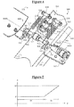
- pantograph 108 With particular reference to the figure 2 , the pantograph 108 will now be described in more detail.
- the pantograph 108 first of all comprises a frame 202 fixed to the roof 106 of the railway vehicle 100.
- the frame 202 comprises a frame 204 and electrical insulators 206 connecting the frame 204 to the roof 106 of the railway vehicle 100.
- a mark R is attached to the frame 202.
- the mark R comprises a longitudinal direction L, a vertical direction V and a transverse direction T (perpendicular to the plane of the sheet on the figure 2 ).
- the longitudinal direction L and the vertical direction V together define a vertical plane (the plane of the sheet on the figure 2 ).
- the longitudinal direction L corresponds to the usual horizontal direction in the direction of travel of the rail vehicle 100 when the latter is traveling on a horizontal rail track 102 .
- the vertical direction V corresponds to the usual vertical direction.
- a substantially constant angle is an angle constant within 1 °.
- the pantograph 108 further comprises a bow 208 intended to be in contact with the catenary 104 in order to capture the supply current.
- the catenary 104 is located vertically at a distance from the frame 202 which can vary greatly. For example, this distance can vary between 600 mm and 3600 mm.
- the pantograph 108 further comprises an articulated arm 210 connecting the bow 208 to the frame 202 , so that the bow 208 is at a distance D variable of the frame 202.
- the articulated arm 210 is designed to develop vertically to move the bow 208 relative to the frame 202 in order to maintain the bow 208 in contact with the catenary 104.
- the articulated arm 210 is designed to, on the one hand, develop vertically in order to move the bow 208 away from the frame 202 when the distance between the catenary 104 and the frame 202 increases and, on the other hand, to fold vertically in order to bring the bow 208 closer to the frame 202 when the distance between the catenary 104 and the frame 202 decreases.
- the articulated arm 210 is in two parts. It thus comprises a main lower rod 214 mounted transversely to pivot on the frame 202 (for example, on the frame 204 ).
- the main lower rod 214 has an angle A1 with the longitudinal direction L.
- the articulated arm 210 further comprises a main upper rod 216 mounted transversely to pivot on the main lower rod 214 and having an angle A2 with the longitudinal direction L.
- the bow 208 is mounted transversely to pivot on the main upper rod 216.
- the articulated arm 210 further comprises an auxiliary lower rod 218 mounted transversely to pivot on the frame 202 (for example, on the frame 204 ) and on the upper main rod 216 , so as to control the angle A2 of the upper main rod 216 at the angle A1 of the main lower rod 214 , so that increasing the angle A1 causes the angle A2 to increase.
- an auxiliary lower rod 218 mounted transversely to pivot on the frame 202 (for example, on the frame 204 ) and on the upper main rod 216 , so as to control the angle A2 of the upper main rod 216 at the angle A1 of the main lower rod 214 , so that increasing the angle A1 causes the angle A2 to increase.
- the articulated arm 210 further comprises an auxiliary upper rod 220 mounted transversely to pivot on the main lower rod 214 and on the bow 208 , so that the bow 208 keeps a substantially constant angle with the longitudinal direction L regardless of the development of the articulated arm 210.
- the pantograph 108 further includes a return device 222 designed to induce the articulated arm 210 to expand.
- the return device 222 is for example designed to rotate the main lower rod 214 in order to increase the angle A1.
- the return device 222 for example comprises an air cushion, a spring or else an electric motor.
- the pantograph ensures constant pressure on the catenary.
- this pressure is susceptible to change due to aerodynamic effects.
- the pantograph 108 further comprises a pressure compensation device 224 mounted on the articulated arm 210.
- the pressure compensation device 224 firstly comprises a fin system 402 , also referred to as a fin assembly, which comprises in the example described two fins 404, 406 having respective concavities oriented opposite the one from the other. This opposite orientation of the concavities makes it possible to obtain the same aerodynamic effect, whatever the direction of travel of the rail vehicle 100.
- a fin system 402 also referred to as a fin assembly
- the two ailerons have different angles of incidence, so that the aerodynamic effect is variable depending on the direction of travel of the rail vehicle.
- the fin system 402 further comprises two connecting rods 408 , 410 to which the two fins 404 , 406 are respectively fixed, as well as a shaft 412 at the ends of which the connecting rods 408 , 410 are respectively fixed.
- This shaft 412 has a main axis A412 , which is transverse with reference to the direction L and which forms the overall pivot axis of the aileron system on the second range of development of the articulated arm 210 , as will be seen below.
- the fin system 402 further comprises a roller 414 mounted on the shaft 412.
- the two fins 404 , 406 are located transversely on either side of the main upper rod 216.
- the ailerons 404 , 406 have, with the longitudinal direction L, a respective angle denoted ⁇ 404, ⁇ 406. Each of these angles is taken between this direction L and the line, respectively D404 , D406 passing through the opposite free ends of each fin.
- ⁇ 404 a respective angle denoted
- ⁇ 406 a respective angle denoted ⁇ 404, ⁇ 406.
- Each of these angles is taken between this direction L and the line, respectively D404 , D406 passing through the opposite free ends of each fin.
- the variation of the angle ⁇ 406 has been illustrated with the development of the pantograph, it being understood that the variation of the other angle ⁇ 404 is identical.
- the pressure compensation device 224 further comprises an orientation device 502 of the aileron system 402 , and in particular of the ailerons 404 , 406 , designed to vary the angle ⁇ 404, ⁇ 406 according to the development of the articulated arm 210.
- the development of the articulated arm 210 comprises in particular a first development range in which the bow 208 moves between a low position and an intermediate position separated by a first vertical distance D1 of at least 500 mm, for example between 2,000 mm and 3,000 mm, for example equal to 2,500 mm, and a second development range in which the bow 208 moves between the intermediate position and a high position separated by a second vertical distance D2 of at least 500 mm, for example between 500 mm and 1500 mm, for example equal to 1000 mm.
- the orientation device 502 is designed to, on the first range of deployment of the articulated arm 210 , give a first type of profile at each angle ⁇ 404, ⁇ 406. In particular, this angle can be substantially constant over this first range.
- this orientation device 502 is designed to, on the second range of deployment of the articulated arm 210 , give another type of profile at each angle ⁇ 404, ⁇ 406. In particular, this angle can undergo a significant increase over this second range, in particular by more than 1 °, for example from 20 ° to 40 °, for example by 30 °.
- the orientation device 502 firstly comprises two additional connecting rods 504 , 506 , on which the connecting rods 408, 410 are mounted transversely to pivot about a respective transverse axis A408, A410.
- the two axes A408, A410 are mutually coincident, while being parallel to the axis A412 above.
- the variation of the angle ⁇ 404, ⁇ 406 can be controlled by the additional connecting rods 504 , 506 , which are called first control members.
- the connecting rod 506 comprises a hollow base 506A , of tubular shape, in the interior volume of which is received a roller 507.
- the latter is mounted to pivot on the auxiliary upper rod 220 , about an axis A507 parallel to that A412.
- This connecting rod 506 also has a solid body 506B , fixed to the top of the base 506A by any suitable means, in particular removably.
- the upper end of the body 506B opposite the base, has the shape of a fork.
- the latter defines a notch 510 , delimited by a front stopper 514 and a rear stopper 518.
- the notch and the two stops of the connecting rod 504 have been referenced 508, 512 and 516 .
- each first control member 504 , 506 is firstly mounted to pivot on the main upper rod 216 , about a respective transverse axis A504, A506. Furthermore, the base of each of these control members can slide along the roller 507 , according to the arrow F506 at the figure 6 .
- Each control member 504 , 506 therefore has a sliding pivot type connection with this rod 220. In this way, as will be seen better below, these members 504 , 506 keep a substantially constant angle with the longitudinal direction L , whatever the development of the articulated arm 210.
- the orientation device 502 further comprises a U-shaped angle 524 , fixed to the main upper rod 216 by any suitable means.
- This angle has two wings 525 extending from a core 526.
- the outer surface 527 of this core 526 opposite the wings 525 , is adapted to come into abutment against the roller 414.
- this stop surface 527 is rectilinear, while being perpendicular to the upper surface of the rod 216.
- the variation of the angle ⁇ 404, ⁇ 406 can also be controlled by this core 526 and its stop surface 527 , which form a second control member within the meaning of the invention.
- the orientation device 502 further comprises two springs 520 , 522 , a first end of which is fixed to a wing 525 of the angle iron, via a respective pin 528 , and the other end of which is fixed to the shaft 412 of the system. fin.
- the springs 520 , 522 are designed to operate in traction in order to maintain this shaft 412 against the front stops 512 , 514 on the first range of development of the articulated arm 210 , as illustrated in particular in figure 6 or 7 , or hold the roller 414 against the surface of stop 527 on the second development range of the articulated arm 210 , as illustrated in particular in figure 9 or 10 .
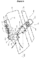
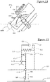
- the low position of the bow 208 is illustrated on this figure 6 , as well as on the figure 11 .
- the latter is a block diagram illustrating the various mechanical elements, described above, as well as the connections existing between these elements.
- the articulated arm 210 is in a folded configuration.
- the stop 527 is at a distance from the roller 414 , so that the springs 520 , 522 immobilize the shaft 412 against the front stop 514 , pressing it against the latter.
- the ailerons 404, 406 therefore have a substantially zero angle with the support pieces 408, 410 , which themselves have a substantially zero angle with the longitudinal direction L.
- the ailerons 404, 406 have an angle ⁇ 404, ⁇ 406 substantially null with the longitudinal direction L, as shown on figure 6 .
- ailerons 404, 406 have oppositely oriented concavities and have an angle of incidence of 0 °, substantially zero lift is applied by ailerons 404, 406 on the articulated arm 210.
- the bow 208 is now located between its low position and its intermediate position.
- the stopper 524 is always at a distance from the roller 414 so that, as on the figures 6 and 11 , the springs 520 , 522 immobilize the shaft 412 against the front stop 512 , 514.
- the ailerons 404, 406 consequently retain an angle ⁇ 404, ⁇ 406 which is substantially zero with the longitudinal direction L.
- the bow 208 is now in its so-called intermediate position.
- the stop 527 comes into contact with the roller 414 , the shaft 412 still being immobilized against the front stop 512, 514 by the springs 520, 522.
- the ailerons 404, 406 therefore maintain a substantially zero angle with the longitudinal direction L.
- the first range of development of the articulated arm 210 is delimited by the extreme positions of the figures 6 and 11 on the one hand, as well as 8 and 13 on the other hand.
- the variation of the angle ⁇ 404, ⁇ 406 is controlled only by the connecting rods 504, 506. Since these connecting rods have a constant angle with the direction L and the shaft 414 is immobilized against these connecting rods under the action of the springs 520 , 522 , the aforementioned angle ⁇ 404, ⁇ 406 is also constant, in this case zero in the example illustrated.
- the bow 208 is now located between its intermediate position and its high position.
- the displacement of the lower rod 220 relative to the upper one 216 caused an additional rotation of the rod 506 around its axis A506 in the clockwise direction.
- the roller 414 being already in contact with the stop 527 from the intermediate position, the rotation of the connecting rod 506 has caused the inclination of the other connecting rod 410 resting on the stop 527 through a rotation of the connecting rod 410 around the axis A410 in the counterclockwise direction and the sliding of the roller 414 upwards on the stop 527. Due to the fixed connections between the connecting rod 408 or 410 and the aileron 404 or 406 , the latter undergoes the same inclination.
- the angle ⁇ 404, ⁇ 406 no longer has a constant value, as in the first range of deployment described above.
- this angle increases as the articulated arm 210 unfolds, in this case in a linear fashion.
- an increasing lift directed upwards is applied by the aileron 406 on the articulated arm 210 , which has the effect of causing the articulated arm 210 to develop in order to compensate for the increasing reverse aerodynamic force which is applied to the pantograph.
- the figures 10 and 15 finally illustrate the bow 208 in its upper terminal position.
- the shaft 412 is pushed back along the notches, until it is in the vicinity of the rear stops 516 , 518. It will be noted that, during its movement away from the stops 510, 512, this shaft 412 is not in contact. contact with the bottom of the aforementioned notches.
- the roller 414 continued to roll upward on the stopper 527 and the connecting rod 410 continued to rotate around the axis A410 without the counterclockwise direction.
- the angle ⁇ 404, ⁇ 406 of the ailerons 404, 406 with the longitudinal direction has a maximum value, in the configuration of these figures 10 and 15 .
- the second range of development of the articulated arm 210 is delimited by the extreme positions of the figures 8 and 13 on the one hand, as well as 10 and 15 on the other hand.
- the variation of the angle ⁇ 404, ⁇ 406 is mainly controlled by the stop 527 , along which rolls and pivots the roller 414.
- the aforementioned angle ⁇ 404, ⁇ 406 is now variable, in this case linearly increasing in the example shown.
- the aileron orientation mechanism 404, 406 may use a cam profile.
- the angle ⁇ 404, ⁇ 406 formed by the ailerons with the longitudinal direction can for example increase non-linearly, along the second range.
- the lift / downforce compensation of the pantograph necessary for the correct effort at the head involves a variation in the angle of the ailerons which is relatively linear as a function of the development of the pantograph in its second range.
- this could potentially require a greater aileron angle variation towards the start of the variation change and less towards the end, which in this case would require a curve, for example of the generally logarithmic type.
- this could potentially require a smaller aileron angle variation towards the start of the variation change and more towards the end, which in this case would require a curve, for example of the globally exponential type.
- the angle ⁇ 404, ⁇ 406 formed by the ailerons with the longitudinal direction is constant but not zero.
- the roller 507 slides on a non-rectilinear surface, it is possible to obtain an angle ⁇ 404, ⁇ 406 which is not constant.
- the variation profile of this angle, along this first range remains different from its variation profile, along the second range.
- the variation in inclination of the ailerons 404 , 406 is restrained by the front stops 512 , 514 and rear 516 , 518 and by the sliding pivot type connection, provided by the mechanical elements 506A and 507.
- the tension springs 520 , 522 can be replaced by torsion springs around the axis A412 and resting on the axis A410 , or else around the axis A410 and resting on the axis A412.
Landscapes
- Engineering & Computer Science (AREA)
- Power Engineering (AREA)
- Transportation (AREA)
- Mechanical Engineering (AREA)
- Current-Collector Devices For Electrically Propelled Vehicles (AREA)
Claims (15)
- Scherenstromabnehmer (108), Folgendes beinhaltend:- ein Gestell (202), an dem eine Markierung (R) angebracht ist, wobei die Markierung (R) eine Längsrichtung (L), eine vertikale Richtung (V) und eine Querrichtung (T) beinhaltet, wobei die Längsrichtung (L) und die vertikale Richtung (V) gemeinsam eine vertikale Ebene definieren,- einen Bogen (208), der dazu bestimmt ist, in Kontakt mit einer Oberleitung (104) zu sein, um einen Versorgungsstrom abzunehmen, der durch die Oberleitung (104) strömt,- einen Gelenkarm (210), der den Bogen (208) mit dem Gestell (202) verbindet, und gestaltet ist, um sich vertikal zu entfalten, um den Bogen (208) in Bezug auf das Gestell (202) in der vertikalen Ebene zu bewegen, wobei der Arm eine obere Hauptstange (216) und eine obere Hilfsstange (220) umfasst,- eine Rippenanordnung, umfassend mindestens eine Rippe (404, 406), die in der vertikalen Ebene einen Winkel (α404, α406) mit der Längsrichtung (L) bildet,- eine Ausrichtungsvorrichtung (502) der Rippe (404, 406), die gestaltet ist, um den Winkel (α404, α406) der Rippe (404, 406) mit der Längsrichtung (L) in Abhängigkeit von der Entfaltung des Gelenkarmes (210) variieren zu lassen,- wobei diese Ausrichtungsvorrichtung Mittel (504, 506; 526, 527) zum Steuern der Variation des Winkels der Rippe umfasst, wobei diese Mittel zum Steuern mindestens ein erstes Steuerorgan (504, 506) umfassen, das sowohl auf der oberen Hauptstange (216) und auf der oberen Hilfsstange (220) des Armes (210) angelenkt ist
wobei der Scherenstromabnehmer dadurch gekennzeichnet ist, dass die Mittel zum Steuern der Variation des Winkels der Rippe weiter mindestens ein zweites Steuerorgan (526, 527) umfassen, das fest mit der oberen Hauptstange (216) verbunden ist,
wobei diese Ausrichtungsvorrichtung (502) angepasst ist, damit- in einem ersten Entfaltungsbereich des Gelenkarmes (210), in dem sich der Bogen (208) zwischen einer unteren Position und einer Zwischenposition bewegt, das erste Steuerorgan (504, 506) imstande ist, die Variation des Winkels (α404, α406) der Rippe unabhängig vom zweiten Steuerorgan (526, 527) zu steuern, um der Rippe in diesem ersten Bereich ein erstes Winkelvariationsprofil zu verleihen;- in einem zweiten Entfaltungsbereich des Gelenkarmes (210), in dem sich der Bogen (208) zwischen der Zwischenposition und einer oberen Position bewegt, das zweite Steuerorgan (526, 527) imstande ist, die Variation des Winkels (α404, α406) der Rippe zu steuern, um der Rippe in diesem zweiten Bereich ein zweites Winkelvariationsprofil zu verleihen. - Scherenstromabnehmer nach Anspruch 1, wobei das erste Winkelvariationsprofil einem Winkel (α404, α406) mit einem im Wesentlichen konstanten Wert, insbesondere null, entspricht.
- Scherenstromabnehmer nach Anspruch 1 oder 2, wobei das zweite Winkelvariationsprofil einem Winkel (α404, α406) mit insbesondere linear steigendem Wert entspricht.
- Scherenstromabnehmer nach einem der vorstehenden Ansprüche, wobei das erste Steuerorgan (504, 506) durch eine erste Schwenkverbindung auf der oberen Hauptstange (216), und durch eine Punktverbindung auf der oberen Hilfsstange (220) angelenkt ist.
- Scherenstromabnehmer nach einem der vorstehenden Ansprüche, wobei das erste Steuerorgan (504, 506) auf der oberen Hauptstange (216) und auf der oberen Hilfsstange (220) angelenkt ist, um einen im Wesentlichen konstanten Winkel it der Längsrichtung (L) zu behalten.
- Scherenstromabnehmer nach Anspruch 4 oder 5, wobei das erste Steuerorgan (506) eine hohle Basis (506A) umfasst, in deren Innenvolumen eine Rolle (507) aufgenommen ist, die schwenkbar auf der oberen Hilfsstange (220) um eine Querachse (A507) herum montiert ist, sowie einen massiven Körper (506B), der an der Basis (506A) insbesondere abnehmbar befestigt ist, wobei der Körper schwenkbar auf der oberen Hauptstange (216) um eine Querachse (A504, A506) herum montiert ist.
- Scherenstromabnehmer nach einem der vorstehenden Ansprüche, wobei die Rippe (404, 406) auf dem ersten Steuerorgan (504, 506) angelenkt ist, und der Scherenstromabnehmer Immobilisierungsmittel (520, 522) umfasst, die geeignet sind, die Rippenanordnung (404, 406) in Bezug auf das erste Steuerorgan (504, 506) in einer Immobilisierungsposition in dem ersten Entfaltungsbereich zu immobilisieren.
- Scherenstromabnehmer nach dem vorstehenden Anspruch, wobei die Rippe (404, 406) anhand einer Schwenkverbindung (A410) auf dem ersten Steuerorgan (504, 506) angelenkt ist.
- Scherenstromabnehmer nach Anspruch 7 oder 8, wobei die Immobilisierungsmittel eine elastische Vorrichtung (520, 522), insebsondere mindestens eine Zugfeder (520, 522) umfassen, deren erstes Ende fest mit der Rippenanordnung (404, 406) verbunden ist, und deren anderes Ende fest mit der oberen Hauptstange (216) verbunden ist.
- Scherenstromabnehmer nach einem der Ansprüche 7 bis 9, wobei das zweite Steuerorgan (526, 527) imstande ist, die Rippenanordnung aus ihrer Immobilisierungsposition in dem zweiten Entfaltungsbereich zu verschieben.
- Scherenstromabnehmer nach Anspruch 10, wobei die Rippe (404, 406) auf dem zweiten Steuerorgan (526, 527) während des zweiten Entwicklungsbereichs des Gelenkarms (201) anhand einer Punktverbindung (414, 527) angelenkt ist.
- Scherenstromabnehmer nach einem der vorstehenden Ansprüche, wobei das zweite Steuerorgan ein Anschlag (526) ist, der eine Anschlagfläche (527) aufweist, wobei die Rippenanordnung (504, 506) imstande ist, sich entlang mindestens eines Teils dieser Anschlagfläche (527) in dem zweiten Entfaltungsbereich zu verschieben.
- Scherenstromabnehmer nach Anspruch 12, wobei die Anschlagfläche eine Nockenfläche ist.
- Scherenstromabnehmer nach Anspruch 12 oder 13, wobei die Rippenanordnung eine Welle (412) umfasst, die mit einer Rolle (414) versehen ist, wobei die Rolle geeignet ist, sich entlang mindestens eines Teils der Anschlagfläche (527) zu verschieben.
- Schienenfahrzeug (100), umfassend:- ein Dach (106),- einen Scherenstromabnehmer (108) nach einem der vorstehenden Ansprüche,
wobei das Gestell (202) des Scherenstromabnehmers am Dach (106) des Schienenfahrzeugs (100) befestigt ist.
Applications Claiming Priority (2)
| Application Number | Priority Date | Filing Date | Title |
|---|---|---|---|
| FR1751205A FR3062824B1 (fr) | 2017-02-15 | 2017-02-15 | Pantographe et vehicule ferroviaire comportant un tel pantographe |
| PCT/FR2018/050328 WO2018150129A1 (fr) | 2017-02-15 | 2018-02-12 | Pantographe et véhicule ferroviaire comportant un tel pantographe |
Publications (2)
| Publication Number | Publication Date |
|---|---|
| EP3582991A1 EP3582991A1 (de) | 2019-12-25 |
| EP3582991B1 true EP3582991B1 (de) | 2020-09-16 |
Family
ID=58547719
Family Applications (1)
| Application Number | Title | Priority Date | Filing Date |
|---|---|---|---|
| EP18706812.7A Active EP3582991B1 (de) | 2017-02-15 | 2018-02-12 | Scherenstromabnehmer und schienenfahrzeug mit solch einem scherenstromabnehmer |
Country Status (4)
| Country | Link |
|---|---|
| EP (1) | EP3582991B1 (de) |
| ES (1) | ES2831010T3 (de) |
| FR (1) | FR3062824B1 (de) |
| WO (1) | WO2018150129A1 (de) |
Families Citing this family (5)
| Publication number | Priority date | Publication date | Assignee | Title |
|---|---|---|---|---|
| FR3092040B1 (fr) | 2019-01-28 | 2021-01-01 | Faiveley Transp Tours | Pantographe et vehicule ferroviaire comportant un tel pantographe |
| AT523329B1 (de) * | 2019-12-17 | 2021-10-15 | Siemens Mobility Austria Gmbh | Wippe für einen Stromabnehmer eines Fahrzeugs |
| CN111907332A (zh) * | 2020-08-04 | 2020-11-10 | 北京中车赛德铁道电气科技有限公司 | 一种受电弓导流板设计方法 |
| CN112829595B (zh) * | 2021-02-25 | 2022-06-10 | 西南交通大学 | 一种具有射流器件的受电弓装置 |
| CN115570983B (zh) * | 2022-10-26 | 2024-10-11 | 中南大学 | 一种列车用自适应升力受电弓 |
Family Cites Families (9)
| Publication number | Priority date | Publication date | Assignee | Title |
|---|---|---|---|---|
| JP2817124B2 (ja) | 1992-05-15 | 1998-10-27 | 東洋電機製造株式会社 | シングルアーム形パンタグラフの揚力制御翼 |
| JP3266777B2 (ja) | 1995-03-06 | 2002-03-18 | 川崎重工業株式会社 | パンタグラフの押上力制御方法および装置 |
| JPH08275303A (ja) * | 1995-03-31 | 1996-10-18 | Hitachi Ltd | 集電装置 |
| FR2813815B1 (fr) * | 2000-09-14 | 2003-02-21 | Christian Salesse | Dispositif d'equilibrage d'une force, a hautes performances |
| FR2850330A1 (fr) * | 2003-01-24 | 2004-07-30 | Jean Marc Loriot | Le pamtographe haute performance |
| JP2007252114A (ja) * | 2006-03-16 | 2007-09-27 | Railway Technical Res Inst | 集電装置の揚力制御構造 |
| KR20130075577A (ko) | 2011-12-27 | 2013-07-05 | 한국철도기술연구원 | 고속철도용 팬터그래프의 양력조절장치 |
| RU2481200C1 (ru) | 2012-01-12 | 2013-05-10 | Евгений Александрович Оленев | Способ работы токоприемника на электрическом подвижном составе |
| DE102013203199A1 (de) * | 2013-02-27 | 2014-08-28 | Siemens Aktiengesellschaft | Stromabnehmer für ein Fahrzeug |
-
2017
- 2017-02-15 FR FR1751205A patent/FR3062824B1/fr active Active
-
2018
- 2018-02-12 EP EP18706812.7A patent/EP3582991B1/de active Active
- 2018-02-12 WO PCT/FR2018/050328 patent/WO2018150129A1/fr not_active Ceased
- 2018-02-12 ES ES18706812T patent/ES2831010T3/es active Active
Non-Patent Citations (1)
| Title |
|---|
| None * |
Also Published As
| Publication number | Publication date |
|---|---|
| ES2831010T3 (es) | 2021-06-07 |
| EP3582991A1 (de) | 2019-12-25 |
| FR3062824A1 (fr) | 2018-08-17 |
| FR3062824B1 (fr) | 2019-03-15 |
| WO2018150129A1 (fr) | 2018-08-23 |
Similar Documents
| Publication | Publication Date | Title |
|---|---|---|
| EP3582991B1 (de) | Scherenstromabnehmer und schienenfahrzeug mit solch einem scherenstromabnehmer | |
| EP0780250B1 (de) | Feineinstellung eines MacPherson-Federbeines: Vorrichtung zur Einstellung auf dem Federbein und Bank zum Messen | |
| EP0274777B1 (de) | Mit gesteuerter Deformation profilierter Flügel und Anwendung bei Schlagflügelflugzeugen | |
| FR3065407A1 (fr) | Module d'accoudoir pour siege de vehicule automobile | |
| FR2473466A1 (fr) | Avion a voilure fixe comportant des surfaces portantes placees en tandem | |
| WO2012101352A1 (fr) | Avion motorisé à structure mixte hydrodynamique et aérodynamique pour le décollage et l'atterrissage sur l'eau, le sol ou la neige | |
| EP0352178A1 (de) | Vorrichtung zur Einstellung des Sturzes an einem Fahrzeug | |
| EP0757955A1 (de) | System zur Steuerung eines an einer Fahrzeugstruktur angelenkten Steuerruders | |
| EP3917797B1 (de) | Scherenstromabnehmer und schienenfahrzeug mit solch einem scherenstromabnehmer | |
| FR2983160A1 (fr) | Dispositif de reglage du parallelisme d'un train arriere de vehicule automobile | |
| EP3060455B1 (de) | Kraftfahrzeugvorderstruktur mit einem unter dem stossfänger angeordneten beweglichen spoiler | |
| CA3082924C (fr) | Vehicule destine a une ligne electrique | |
| EP3670307A1 (de) | Aerodynamischer spoiler mit gelenke | |
| FR2915068A1 (fr) | Dispositif de reglage de la flexibilite de latte(s)d'un sommier a latte(s)et sommier equipe d'un tel dispositif. | |
| FR3107248A1 (fr) | Déflecteur de custode rotatif couplé à un conduit | |
| FR2997118A1 (fr) | Dispositif a compensation pour recouvrir et decouvrir une surface par un element de couverture enroulable | |
| FR3166606A1 (fr) | Système de modification de traînée adaptable pour véhicule automobile | |
| WO2019223917A1 (fr) | Dispositif déflecteur aérodynamique situé à l'avant d'un véhicule automobile | |
| EP1675740B1 (de) | Luftablenkvorrichtung für ein auto mit schiebedach | |
| FR3067992B1 (fr) | Repose-pieds interieur motorise pour vehicule automobile. | |
| FR2974058A1 (fr) | Quille de bateau escamotable | |
| FR2636592A1 (fr) | Surface aerodynamique orientable pour un aeronef | |
| FR2673591A1 (fr) | Volets aerodynamiques commandes pour vehicules terrestres assurant une meilleure adherence au sol et reduisant l'effort de freinage. | |
| FR2927277A1 (fr) | Dispositif pour adapter un mecanisme de suspension de vehicule | |
| EP1857306A1 (de) | Vorrichtung, die das Kontrollieren der langsamen Entspannung der Stoßdämpfer ein und derselben Vorderachse eines Fahrzeugs in Abhängigkeit von den Beanspruchungen beim Aufschaukeln und Rollen des Fahrzeugs ermöglicht |
Legal Events
| Date | Code | Title | Description |
|---|---|---|---|
| STAA | Information on the status of an ep patent application or granted ep patent |
Free format text: STATUS: UNKNOWN |
|
| STAA | Information on the status of an ep patent application or granted ep patent |
Free format text: STATUS: THE INTERNATIONAL PUBLICATION HAS BEEN MADE |
|
| PUAI | Public reference made under article 153(3) epc to a published international application that has entered the european phase |
Free format text: ORIGINAL CODE: 0009012 |
|
| STAA | Information on the status of an ep patent application or granted ep patent |
Free format text: STATUS: REQUEST FOR EXAMINATION WAS MADE |
|
| 17P | Request for examination filed |
Effective date: 20190916 |
|
| AK | Designated contracting states |
Kind code of ref document: A1 Designated state(s): AL AT BE BG CH CY CZ DE DK EE ES FI FR GB GR HR HU IE IS IT LI LT LU LV MC MK MT NL NO PL PT RO RS SE SI SK SM TR |
|
| AX | Request for extension of the european patent |
Extension state: BA ME |
|
| DAV | Request for validation of the european patent (deleted) | ||
| DAX | Request for extension of the european patent (deleted) | ||
| GRAP | Despatch of communication of intention to grant a patent |
Free format text: ORIGINAL CODE: EPIDOSNIGR1 |
|
| STAA | Information on the status of an ep patent application or granted ep patent |
Free format text: STATUS: GRANT OF PATENT IS INTENDED |
|
| INTG | Intention to grant announced |
Effective date: 20200605 |
|
| GRAS | Grant fee paid |
Free format text: ORIGINAL CODE: EPIDOSNIGR3 |
|
| GRAA | (expected) grant |
Free format text: ORIGINAL CODE: 0009210 |
|
| STAA | Information on the status of an ep patent application or granted ep patent |
Free format text: STATUS: THE PATENT HAS BEEN GRANTED |
|
| AK | Designated contracting states |
Kind code of ref document: B1 Designated state(s): AL AT BE BG CH CY CZ DE DK EE ES FI FR GB GR HR HU IE IS IT LI LT LU LV MC MK MT NL NO PL PT RO RS SE SI SK SM TR |
|
| REG | Reference to a national code |
Ref country code: GB Ref legal event code: FG4D Free format text: NOT ENGLISH |
|
| REG | Reference to a national code |
Ref country code: CH Ref legal event code: EP |
|
| REG | Reference to a national code |
Ref country code: DE Ref legal event code: R096 Ref document number: 602018007906 Country of ref document: DE |
|
| REG | Reference to a national code |
Ref country code: IE Ref legal event code: FG4D Free format text: LANGUAGE OF EP DOCUMENT: FRENCH |
|
| REG | Reference to a national code |
Ref country code: AT Ref legal event code: REF Ref document number: 1313864 Country of ref document: AT Kind code of ref document: T Effective date: 20201015 |
|
| PG25 | Lapsed in a contracting state [announced via postgrant information from national office to epo] |
Ref country code: GR Free format text: LAPSE BECAUSE OF FAILURE TO SUBMIT A TRANSLATION OF THE DESCRIPTION OR TO PAY THE FEE WITHIN THE PRESCRIBED TIME-LIMIT Effective date: 20201217 Ref country code: NO Free format text: LAPSE BECAUSE OF FAILURE TO SUBMIT A TRANSLATION OF THE DESCRIPTION OR TO PAY THE FEE WITHIN THE PRESCRIBED TIME-LIMIT Effective date: 20201216 Ref country code: SE Free format text: LAPSE BECAUSE OF FAILURE TO SUBMIT A TRANSLATION OF THE DESCRIPTION OR TO PAY THE FEE WITHIN THE PRESCRIBED TIME-LIMIT Effective date: 20200916 Ref country code: BG Free format text: LAPSE BECAUSE OF FAILURE TO SUBMIT A TRANSLATION OF THE DESCRIPTION OR TO PAY THE FEE WITHIN THE PRESCRIBED TIME-LIMIT Effective date: 20201216 Ref country code: HR Free format text: LAPSE BECAUSE OF FAILURE TO SUBMIT A TRANSLATION OF THE DESCRIPTION OR TO PAY THE FEE WITHIN THE PRESCRIBED TIME-LIMIT Effective date: 20200916 Ref country code: FI Free format text: LAPSE BECAUSE OF FAILURE TO SUBMIT A TRANSLATION OF THE DESCRIPTION OR TO PAY THE FEE WITHIN THE PRESCRIBED TIME-LIMIT Effective date: 20200916 |
|
| REG | Reference to a national code |
Ref country code: NL Ref legal event code: MP Effective date: 20200916 |
|
| PG25 | Lapsed in a contracting state [announced via postgrant information from national office to epo] |
Ref country code: RS Free format text: LAPSE BECAUSE OF FAILURE TO SUBMIT A TRANSLATION OF THE DESCRIPTION OR TO PAY THE FEE WITHIN THE PRESCRIBED TIME-LIMIT Effective date: 20200916 Ref country code: LV Free format text: LAPSE BECAUSE OF FAILURE TO SUBMIT A TRANSLATION OF THE DESCRIPTION OR TO PAY THE FEE WITHIN THE PRESCRIBED TIME-LIMIT Effective date: 20200916 |
|
| REG | Reference to a national code |
Ref country code: LT Ref legal event code: MG4D |
|
| PG25 | Lapsed in a contracting state [announced via postgrant information from national office to epo] |
Ref country code: CZ Free format text: LAPSE BECAUSE OF FAILURE TO SUBMIT A TRANSLATION OF THE DESCRIPTION OR TO PAY THE FEE WITHIN THE PRESCRIBED TIME-LIMIT Effective date: 20200916 Ref country code: PT Free format text: LAPSE BECAUSE OF FAILURE TO SUBMIT A TRANSLATION OF THE DESCRIPTION OR TO PAY THE FEE WITHIN THE PRESCRIBED TIME-LIMIT Effective date: 20210118 Ref country code: RO Free format text: LAPSE BECAUSE OF FAILURE TO SUBMIT A TRANSLATION OF THE DESCRIPTION OR TO PAY THE FEE WITHIN THE PRESCRIBED TIME-LIMIT Effective date: 20200916 Ref country code: EE Free format text: LAPSE BECAUSE OF FAILURE TO SUBMIT A TRANSLATION OF THE DESCRIPTION OR TO PAY THE FEE WITHIN THE PRESCRIBED TIME-LIMIT Effective date: 20200916 Ref country code: SM Free format text: LAPSE BECAUSE OF FAILURE TO SUBMIT A TRANSLATION OF THE DESCRIPTION OR TO PAY THE FEE WITHIN THE PRESCRIBED TIME-LIMIT Effective date: 20200916 Ref country code: LT Free format text: LAPSE BECAUSE OF FAILURE TO SUBMIT A TRANSLATION OF THE DESCRIPTION OR TO PAY THE FEE WITHIN THE PRESCRIBED TIME-LIMIT Effective date: 20200916 |
|
| PG25 | Lapsed in a contracting state [announced via postgrant information from national office to epo] |
Ref country code: AL Free format text: LAPSE BECAUSE OF FAILURE TO SUBMIT A TRANSLATION OF THE DESCRIPTION OR TO PAY THE FEE WITHIN THE PRESCRIBED TIME-LIMIT Effective date: 20200916 Ref country code: IS Free format text: LAPSE BECAUSE OF FAILURE TO SUBMIT A TRANSLATION OF THE DESCRIPTION OR TO PAY THE FEE WITHIN THE PRESCRIBED TIME-LIMIT Effective date: 20210116 Ref country code: PL Free format text: LAPSE BECAUSE OF FAILURE TO SUBMIT A TRANSLATION OF THE DESCRIPTION OR TO PAY THE FEE WITHIN THE PRESCRIBED TIME-LIMIT Effective date: 20200916 |
|
| REG | Reference to a national code |
Ref country code: ES Ref legal event code: FG2A Ref document number: 2831010 Country of ref document: ES Kind code of ref document: T3 Effective date: 20210607 |
|
| REG | Reference to a national code |
Ref country code: DE Ref legal event code: R097 Ref document number: 602018007906 Country of ref document: DE |
|
| PG25 | Lapsed in a contracting state [announced via postgrant information from national office to epo] |
Ref country code: SK Free format text: LAPSE BECAUSE OF FAILURE TO SUBMIT A TRANSLATION OF THE DESCRIPTION OR TO PAY THE FEE WITHIN THE PRESCRIBED TIME-LIMIT Effective date: 20200916 |
|
| PLBE | No opposition filed within time limit |
Free format text: ORIGINAL CODE: 0009261 |
|
| STAA | Information on the status of an ep patent application or granted ep patent |
Free format text: STATUS: NO OPPOSITION FILED WITHIN TIME LIMIT |
|
| 26N | No opposition filed |
Effective date: 20210617 |
|
| PG25 | Lapsed in a contracting state [announced via postgrant information from national office to epo] |
Ref country code: DK Free format text: LAPSE BECAUSE OF FAILURE TO SUBMIT A TRANSLATION OF THE DESCRIPTION OR TO PAY THE FEE WITHIN THE PRESCRIBED TIME-LIMIT Effective date: 20200916 |
|
| PG25 | Lapsed in a contracting state [announced via postgrant information from national office to epo] |
Ref country code: MC Free format text: LAPSE BECAUSE OF FAILURE TO SUBMIT A TRANSLATION OF THE DESCRIPTION OR TO PAY THE FEE WITHIN THE PRESCRIBED TIME-LIMIT Effective date: 20200916 |
|
| REG | Reference to a national code |
Ref country code: BE Ref legal event code: MM Effective date: 20210228 |
|
| PG25 | Lapsed in a contracting state [announced via postgrant information from national office to epo] |
Ref country code: CH Free format text: LAPSE BECAUSE OF NON-PAYMENT OF DUE FEES Effective date: 20210228 Ref country code: LI Free format text: LAPSE BECAUSE OF NON-PAYMENT OF DUE FEES Effective date: 20210228 Ref country code: LU Free format text: LAPSE BECAUSE OF NON-PAYMENT OF DUE FEES Effective date: 20210212 |
|
| PG25 | Lapsed in a contracting state [announced via postgrant information from national office to epo] |
Ref country code: IE Free format text: LAPSE BECAUSE OF NON-PAYMENT OF DUE FEES Effective date: 20210212 |
|
| REG | Reference to a national code |
Ref country code: AT Ref legal event code: UEP Ref document number: 1313864 Country of ref document: AT Kind code of ref document: T Effective date: 20200916 |
|
| PG25 | Lapsed in a contracting state [announced via postgrant information from national office to epo] |
Ref country code: BE Free format text: LAPSE BECAUSE OF NON-PAYMENT OF DUE FEES Effective date: 20210228 |
|
| PG25 | Lapsed in a contracting state [announced via postgrant information from national office to epo] |
Ref country code: NL Free format text: LAPSE BECAUSE OF NON-PAYMENT OF DUE FEES Effective date: 20200923 Ref country code: CY Free format text: LAPSE BECAUSE OF FAILURE TO SUBMIT A TRANSLATION OF THE DESCRIPTION OR TO PAY THE FEE WITHIN THE PRESCRIBED TIME-LIMIT Effective date: 20200916 |
|
| P01 | Opt-out of the competence of the unified patent court (upc) registered |
Effective date: 20230530 |
|
| PG25 | Lapsed in a contracting state [announced via postgrant information from national office to epo] |
Ref country code: HU Free format text: LAPSE BECAUSE OF FAILURE TO SUBMIT A TRANSLATION OF THE DESCRIPTION OR TO PAY THE FEE WITHIN THE PRESCRIBED TIME-LIMIT; INVALID AB INITIO Effective date: 20180212 |
|
| PG25 | Lapsed in a contracting state [announced via postgrant information from national office to epo] |
Ref country code: SI Free format text: LAPSE BECAUSE OF FAILURE TO SUBMIT A TRANSLATION OF THE DESCRIPTION OR TO PAY THE FEE WITHIN THE PRESCRIBED TIME-LIMIT Effective date: 20200916 |
|
| PG25 | Lapsed in a contracting state [announced via postgrant information from national office to epo] |
Ref country code: MK Free format text: LAPSE BECAUSE OF FAILURE TO SUBMIT A TRANSLATION OF THE DESCRIPTION OR TO PAY THE FEE WITHIN THE PRESCRIBED TIME-LIMIT Effective date: 20200916 |
|
| PG25 | Lapsed in a contracting state [announced via postgrant information from national office to epo] |
Ref country code: MT Free format text: LAPSE BECAUSE OF FAILURE TO SUBMIT A TRANSLATION OF THE DESCRIPTION OR TO PAY THE FEE WITHIN THE PRESCRIBED TIME-LIMIT Effective date: 20200916 |
|
| PG25 | Lapsed in a contracting state [announced via postgrant information from national office to epo] |
Ref country code: TR Free format text: LAPSE BECAUSE OF FAILURE TO SUBMIT A TRANSLATION OF THE DESCRIPTION OR TO PAY THE FEE WITHIN THE PRESCRIBED TIME-LIMIT Effective date: 20200916 |
|
| PGFP | Annual fee paid to national office [announced via postgrant information from national office to epo] |
Ref country code: GB Payment date: 20260119 Year of fee payment: 9 |
|
| PGFP | Annual fee paid to national office [announced via postgrant information from national office to epo] |
Ref country code: ES Payment date: 20260312 Year of fee payment: 9 |
|
| PGFP | Annual fee paid to national office [announced via postgrant information from national office to epo] |
Ref country code: DE Payment date: 20260113 Year of fee payment: 9 |
|
| PGFP | Annual fee paid to national office [announced via postgrant information from national office to epo] |
Ref country code: AT Payment date: 20260113 Year of fee payment: 9 |
|
| PGFP | Annual fee paid to national office [announced via postgrant information from national office to epo] |
Ref country code: IT Payment date: 20260113 Year of fee payment: 9 |
|
| PGFP | Annual fee paid to national office [announced via postgrant information from national office to epo] |
Ref country code: FR Payment date: 20260121 Year of fee payment: 9 |