EP3582872B1 - Verfahren zum abdichten eines vertikalen druckfilters, vertikaler druckfilter und längliches abdichtelement - Google Patents
Verfahren zum abdichten eines vertikalen druckfilters, vertikaler druckfilter und längliches abdichtelement Download PDFInfo
- Publication number
- EP3582872B1 EP3582872B1 EP17777067.4A EP17777067A EP3582872B1 EP 3582872 B1 EP3582872 B1 EP 3582872B1 EP 17777067 A EP17777067 A EP 17777067A EP 3582872 B1 EP3582872 B1 EP 3582872B1
- Authority
- EP
- European Patent Office
- Prior art keywords
- elongated sealing
- sealing member
- ridge portion
- filter
- elongated
- Prior art date
- Legal status (The legal status is an assumption and is not a legal conclusion. Google has not performed a legal analysis and makes no representation as to the accuracy of the status listed.)
- Active
Links
Images





Classifications
-
- B—PERFORMING OPERATIONS; TRANSPORTING
- B01—PHYSICAL OR CHEMICAL PROCESSES OR APPARATUS IN GENERAL
- B01D—SEPARATION
- B01D25/00—Filters formed by clamping together several filtering elements or parts of such elements
- B01D25/12—Filter presses, i.e. of the plate or plate and frame type
- B01D25/127—Filter presses, i.e. of the plate or plate and frame type with one or more movable filter bands arranged to be clamped between the press plates or between a plate and a frame during filtration, e.g. zigzag endless filter bands
-
- B—PERFORMING OPERATIONS; TRANSPORTING
- B01—PHYSICAL OR CHEMICAL PROCESSES OR APPARATUS IN GENERAL
- B01D—SEPARATION
- B01D25/00—Filters formed by clamping together several filtering elements or parts of such elements
- B01D25/12—Filter presses, i.e. of the plate or plate and frame type
- B01D25/21—Plate and frame presses
- B01D25/215—Construction of the filter plates, frames
-
- B—PERFORMING OPERATIONS; TRANSPORTING
- B01—PHYSICAL OR CHEMICAL PROCESSES OR APPARATUS IN GENERAL
- B01D—SEPARATION
- B01D25/00—Filters formed by clamping together several filtering elements or parts of such elements
- B01D25/28—Leaching or washing filter cakes in the filter handling the filter cake for purposes other than regenerating
- B01D25/282—Leaching or washing filter cakes in the filter handling the filter cake for purposes other than regenerating for drying
- B01D25/285—Leaching or washing filter cakes in the filter handling the filter cake for purposes other than regenerating for drying by compression using inflatable membranes
-
- B—PERFORMING OPERATIONS; TRANSPORTING
- B01—PHYSICAL OR CHEMICAL PROCESSES OR APPARATUS IN GENERAL
- B01D—SEPARATION
- B01D29/00—Filters with filtering elements stationary during filtration, e.g. pressure or suction filters, not covered by groups B01D24/00 - B01D27/00; Filtering elements therefor
- B01D29/09—Filters with filtering elements stationary during filtration, e.g. pressure or suction filters, not covered by groups B01D24/00 - B01D27/00; Filtering elements therefor with filtering bands, e.g. movable between filtering operations
-
- F—MECHANICAL ENGINEERING; LIGHTING; HEATING; WEAPONS; BLASTING
- F16—ENGINEERING ELEMENTS AND UNITS; GENERAL MEASURES FOR PRODUCING AND MAINTAINING EFFECTIVE FUNCTIONING OF MACHINES OR INSTALLATIONS; THERMAL INSULATION IN GENERAL
- F16J—PISTONS; CYLINDERS; SEALINGS
- F16J15/00—Sealings
- F16J15/02—Sealings between relatively-stationary surfaces
-
- F—MECHANICAL ENGINEERING; LIGHTING; HEATING; WEAPONS; BLASTING
- F16—ENGINEERING ELEMENTS AND UNITS; GENERAL MEASURES FOR PRODUCING AND MAINTAINING EFFECTIVE FUNCTIONING OF MACHINES OR INSTALLATIONS; THERMAL INSULATION IN GENERAL
- F16J—PISTONS; CYLINDERS; SEALINGS
- F16J15/00—Sealings
- F16J15/16—Sealings between relatively-moving surfaces
- F16J15/32—Sealings between relatively-moving surfaces with elastic sealings, e.g. O-rings
- F16J15/3204—Sealings between relatively-moving surfaces with elastic sealings, e.g. O-rings with at least one lip
- F16J15/3232—Sealings between relatively-moving surfaces with elastic sealings, e.g. O-rings with at least one lip having two or more lips
-
- B—PERFORMING OPERATIONS; TRANSPORTING
- B01—PHYSICAL OR CHEMICAL PROCESSES OR APPARATUS IN GENERAL
- B01D—SEPARATION
- B01D2201/00—Details relating to filtering apparatus
- B01D2201/34—Seals or gaskets for filtering elements
- B01D2201/342—Axial sealings
Definitions
- the invention relates to method for sealing a vertical as pressure filter defined in the preamble of independent claim 1.
- the invention also relates to a vertical pressure filter as defined in the preamble of independent claim 6.
- Publication WO 2010121827A presents a plate component for a filter press system
- Publication GB 2 120 570A presents a filter plate.
- the object of the invention is to extend the service-life of elongated sealing member(s) in a method for sealing a vertical pressure filter and in a vertical pressure filter.
- the vertical pressure filter of the invention is correspondingly characterized by the definitions of independent claim 6.
- Two ridge portions distribute force more even than one ridge portion. This extends the service-life of the elongated sealing member.
- Two ridge portions distribute deformation force more even than one ridge portion, whereby the elongated sealing member is more evenly deformed. This extends the service-life of the elongated sealing member.
- Two ridge portions distribute pressing force more even on a mounting surface of the base portion of the elongated sealing member than one ridge portion and into the adhesive between the elongated sealing member and the circumferential grove. This promotes sealing.
- the elongated sealing member comprises the first ridge portion and the second ridge portion
- adhesive is also pressed into the area that is vertically beneath the portion of the elongated sealing member situated between the first ridge portion and the second ridge portion, because of the higher pressure under the ridge portions at the mounting surface of the base portion of the elongated sealing member than the pressure under the portion between the ridge portions at the mounting surface of the base portion of the elongated sealing member.
- Provision of two ridge portions also reduces shear force in the lateral direction of the elongated sealing member.
- the vertical pressure filter 1 comprises a filter pack 2 comprising a plurality of separate horizontally arranged and vertically movable filter plates 3
- Each filter plate 3 has a lower surface 4 and an upper surface 5.
- the vertical pressure filter 1 comprises an endless movable filter fabric belt 6 arranged in zigzag manner between the filter plates 3.
- the vertical pressure filter 1 comprises closing and opening means 7 for vertically moving said plurality of separate horizontally arranged and vertically movable filter plates 3 against each other into a closed state of the filter pack 2 to form filter chambers 8 between the filter plates 3 and upward facing surface sections 9 of the endless movable filter fabric belt 6 and for vertically moving said plurality of separate horizontally arranged and vertically movable filter plates 3 away from each other into an open state of the filter pack 2 to open said filter chambers 8.
- the method comprises providing an elongated sealing member 10, which is completely formed of elastically deformable material and which comprises a base portion 12 comprising a mounting surface 13, a first ridge portion 14 and an intermediate portion 15 between the base portion 12 and the first ridge portion 14.
- the method comprises attaching the mounting surface 13 of the elongated sealing member 10 to a bottom 16, which can, as shown in the figures, be a plane bottom, in a circumferential groove 11 in the lower surface 4 of at least one separate horizontally arranged and vertically movable filter plate 3 by means of adhesive 17 that is provided between the mounting surface 13 of the elongated sealing member 10 and the bottom 16 of the circumferential groove 11 so that the first ridge portion 14 of the elongated sealing member 10 faces an upward facing surface section 9 of the endless movable filter fabric belt 6.
- the method comprises pressing the elongated sealing member 10 against the upward facing surface section 9 of the endless movable filter fabric belt 6 in the closed state of the filter pack 2 by means of the closing and opening means 7.
- the elongated sealing member 10 that is provided in the method comprises additionally at least one second ridge portion 18 that extends side-by-side, such as in parallel, with the first ridge portion.
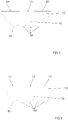
- the elongated sealing member 10 can for example comprise one second ridge portion as shown in figure 6 , two second ridge portions as shown in figure 7 , three second ridge portions as shown in figure 8 , or four second ridge portions as shown in figure 9 .
- the method comprises arranging the elongated sealing member 10 in the circumferential groove 11 in the lower surface 4 of said at least one separate horizontally arranged and vertically movable filter plate 3 so that said at least one second ridge portion 18 of the elongated sealing member 10 also faces said upward facing surface section 9 of the endless movable filter fabric belt 6.
- the method can as exemplified in figures 1 to 5 , comprise providing an elongated sealing member 10, which is in the form of only one elongated sealing strip, and where the first ridge portion 14 and said at least one second ridge portion 18 being integral parts of said only one elongated sealing strip.
- the method can comprise providing only one elongated sealing strip having two opposite ends 19, and arranging the elongated sealing strip in the circumferential groove 11 so that the opposite ends 19 at least one of meet, touches each other, or form a butt joint.
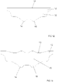
- the method can comprise cutting the opposite ends 19 of the elongated sealing strip so that the opposite ends 19 meet so that the opposite ends 19 are set in an angle and/or in a curved manner with respect to a longitudinal direction of the elongated sealing member 10 as shown in figure 13 .
- An advantage of this is that the joint in the first ridge portion 14 will not be at the same place as the joint in said at least one second ridge portion 18 in the longitudinal direction of the elongated seal strip, which provides for a better seal effect a transversal direction of the elongated seal strip.
- the method can as exemplified in figures 10 and 11 , comprise providing an elongated sealing member 10 comprising only one first ridge portion 14 and only one second ridge portion 18, where said one first ridge portion 14 being a part of a first elongated sealing strip member 20, where said one second ridge portion 18 being a part of a second elongated sealing strip member 21, and where the first elongated sealing strip member 20 and the second elongated sealing strip member 21 being separate parts, and arranging the first elongated sealing member part and the second elongated sealing member part side by side in the circumferential groove 11 so that said one first ridge portion 14 and said one second ridge portion 18 run side by side.
- An advantage of this is that the elongated sealing member 10 can be replaced in part by for example only replacing the worn-out elongated sealing strip member.
- the method can comprise providing the first elongated sealing strip member 20 with opposite ends 19, providing the second elongated sealing strip member 21 with opposite ends 19, arranging the first elongated sealing strip member 20 in the circumferential groove 11 so that the opposite ends 19 of the first elongated sealing strip member 20 least one of meet, touches each other, or form a butt joint, and arranging the second elongated sealing strip member 21 in the circumferential groove 11 so that the opposite ends 19 of the first elongated sealing strip member 20 least one of meet, touches each other, or form a butt joint.
- An advantage of this is that only two joints are formed.
- the method can comprise connecting the first elongated sealing strip member 20 to the second elongated sealing strip member 21 with a tongue and groove joint 22 as is shown in figure 11 .
- An advantage of this is that the first elongated sealing strip member 20 will be better connected to the second elongated sealing strip member 21.
- the vertical pressure filter 1 comprises a filter pack 2 comprising a plurality of separate horizontally arranged and vertically movable filter plates 3, each having a lower surface 4 and an upper surface 5.
- the vertical pressure filter 1 comprises an endless movable filter fabric belt 6 arranged in zigzag manner between the filter plates 3.
- the vertical pressure filter 1 comprises closing and opening means 7 for vertically pressing said plurality of separate horizontally arranged and vertically movable filter plates 3 against each other into a closed state of the filter pack 2 to form filter chambers 8 between filter plates 3 and an upward facing surface section 9 of the endless movable filter fabric belt 6 and for vertically moving said plurality of separate horizontally arranged and vertically movable filter plates 3 away from each other into an open state of the filter pack 2 to open said filter chambers 8.
- the vertical pressure filter 1 an elongated sealing member 10, which is completely formed of elastically deformable material, and which comprises a base portion 12 comprising a mounting surface 13, a first ridge portion 14 and an intermediate portion 15 between the base portion 12 and the first ridge portion 14.
- the mounting surface 13 of the elongated sealing member 10 is attached to a bottom 16, which can be a plane bottom, as shown in the figures, of a circumferential groove 11 in the lower surface 4 of at least one separate horizontally arranged and vertically movable filter plate 3 by means of adhesive 17 that is provided between the mounting surface 13 of the elongated sealing member 10 and the bottom 16 of the circumferential groove 11 so that the first ridge portion 14 of the elongated sealing member 10 faces an upward facing surface section 9 of the endless movable filter fabric belt 6.
- the elongated sealing member 10 is configured to press against the upper surface 5 of the endless movable filter fabric belt 6 in the closed state of the filter pack 2.
- the elongated sealing member 10 comprises additionally at least one second ridge portion 18 that extends side-by-side, such as in parallel, with the first ridge portion 14.
- the elongated sealing member 10 can for example comprise one second ridge portion as shown in figure 6 , two second ridge portions as shown in figure 7 , three second ridge portions as shown in figure 8 , or four second ridge portions as shown in figure 9 .
- the elongated sealing member 10 is arranged in the circumferential groove 11 in the lower surface 4 of said at least one separate horizontally arranged and vertically movable filter plate 3 so that also said at least one second ridge portion 18 of the elongated sealing member 10 faces said upward facing surface section 9 of the endless movable filter fabric belt 6.
- the elongated sealing member 10 of the vertical pressure filter 1 can as exemplified in figures 1 to 5 be in the form of a single elongated sealing strip, and the first ridge portion 14 and the second ridge portion 18 can be integral parts of said single elongated sealing strip.
- the single elongated sealing strip has preferably, but not necessarily, two opposite ends 19, and the sealing strip being arranged in the circumferential groove 11 so that the opposite ends 19 at least one of meet, touches each other, or form a butt joint.
- the opposite ends 19 are preferably, but not necessarily, set in an angle and or in a curved manner with respect to the longitudinal direction of the elongated sealing member 10 as shown in figure 13 .
- An advantage of this is that the joint in the first ridge portion 14 will not be at the same place as the joint in said at least one second ridge portion 18 in the longitudinal direction of the elongated seal strip, which provides for a better seal effect a transversal direction of the elongated seal strip.
- the elongated sealing member 10 of the vertical pressure filter 1 can as exemplified in figures 10 and 11 comprise only one first ridge portion 14 and only one second ridge portion 18, so that the first ridge portion 14 is a part of a first elongated sealing strip member 20 of the elongated sealing member 10, so that the second ridge portion 18 is a part of a second elongated sealing strip member 21 of the elongated sealing member 10, so that the first elongated sealing strip member 20 and the second elongated sealing strip member 21 being separate parts, and so that the first elongated sealing member part and the second elongated sealing member part being arranged side by side in the circumferential groove 11 so that the first ridge portion 14 and the second ridge portion 18 run side by side.
- the first elongated sealing strip member 20 can be in the form of a single first elongated sealing strip member 20 having opposite ends 19, and the second elongated sealing strip member 21 can be in the form of a single second elongated sealing strip member 21 having opposite ends 19, and the first elongated sealing strip member 20 is arranged in the circumferential groove 11 so that the opposite ends 19 of the first elongated sealing strip member 20 at least one of meet, touches each other, or form a butt joint, and the second elongated sealing strip member 21 is arranged in the circumferential groove 11 so that the opposite ends 19 of the first elongated sealing strip member 20 at least one of meet, touches each other, or form a butt joint.
- An advantage of this is that the elongated sealing member 10 can be replaced in part by for example only replacing the worn-out elongated sealing strip member.
- first elongated sealing strip member 20 can be connected to the second elongated sealing strip member 21 with a tongue and groove joint 22.
- An advantage of this is that the first elongated sealing strip member 20 will be better connected to the second elongated sealing strip member 21.
- the elongated sealing member 10 is formed completely of elastically deformable material and comprises a base portion 12 comprising a mounting surface 13, a first ridge portion 14, and an intermediate portion 15 between the base portion 12 and the first ridge portion 14
- the elongated sealing member 10 comprising additionally by at least one second ridge portion 18 that extends side-by-side , such as in parallel, with the first ridge portion 14.
- the elongated sealing member 10 can for example comprise one second ridge portion as shown in figure 6 , two second ridge portions as shown in figure 7 , three second ridge portions as shown in figure 8 , or four second ridge portions as shown in figure 9 .
- the cross-section of the first ridge portion 14 has preferably, but not necessarily, the same dimensions and the same form as the cross-section of said at least one second ridge portion 18.
- the elongated sealing member 10 is preferably, but not necessarily, symmetrical with respect to a center plane that extend in a longitudinal direction of the elongated sealing member 10. An advantage of this is that the elongated sealing member 10 will be more evenly deformed, which extends the service-life of the elongated sealing member 10.
- the base portion 12 of the elongated sealing member 10 is preferably, but not necessarily, symmetrical with respect to a center plane that extend in a longitudinal direction of the elongated sealing member 10.
- the intermediate portion 15 of the elongated sealing member 10 is preferably, but not necessarily, symmetrical with respect to a center plane that extend in a longitudinal direction of the elongated sealing member 10.
- the first ridge portion 14 and said at least one second ridge portion 18 are preferably, but not necessarily, symmetrically arranged with respect to a center plane that extend in a longitudinal direction of the elongated sealing member 10.
- the height of the elongated sealing member 10 is preferably, but not necessarily, the same at the first ridge portion 14 and at said at least one second ridge portion 18.
- the elongated sealing member 10 is preferably, but not necessarily, as shown in figures 6 to 9 , in the form of a one-piece or single-piece elongated sealing strip, and the first ridge portion 14 and the second ridge portion 18 being integral parts of the elongated sealing strip.
- An advantage of this is that the elongated sealing member 10 is easier to mount.
- the elongated sealing member 10 can comprise only one first ridge portion 14 and only one second ridge portion 18, so that the first ridge portion 14 is a part of a first elongated sealing strip member 20 of the elongated sealing member 10, so that the second ridge portion 18 is a part of a second elongated sealing strip member 21 of the elongated sealing member 10, and so that the first elongated sealing strip member 20 and the second elongated sealing strip member 21 being separate parts.
- An advantage of this is that the elongated sealing member 10 can be replaced in part by for example only replacing the worn-out elongated sealing strip member.
- first elongated sealing strip member 20 can be connected to the second elongated sealing strip member 21 with a tongue and groove joint 22.
- An advantage of this is that the first elongated sealing strip member 20 will be better connected to the second elongated sealing strip member 21.
- the elongated sealing member 10 comprises preferably, but not necessarily, any of the following: Natural rubber (NR), Styrene butadiene rubber (SBR), Butyl rubber (IIR), Nitrile rubber (NBR), Epichlorohydrin rubber (ECO, CO), Chloroprene rubber (CR), Urethane rubber (U), Fluoro rubber (FPM), Silicone rubber (Q), Chlorsulphonated polyethylene rubber (CSM), Ethylene propylene rubber (EPDM), Styrenic block copolymers (TPE-s), Polyolefin blends (TPEo), Elastomeric alloys (TPE-v or TPV), Thermoplastic polyurethanes (TPU), Thermoplastic copolyester, and Thermoplastic polyamides
- the elongated sealing member 10 comprises preferably, but not necessarily, adhesive 17 at the mounting surface 13 of the base portion 12, as shown in figures 6 to 11 .
- An advantage of this is that the elongated sealing member 10 is easy to mount.
- the adhesive 17 is preferably, but not necessarily, elastically deformable after curing to withstand alternating opening state and closing state of the filter pack 2.
- the adhesive 17 is preferably, but not necessarily, selected so that it can attach to elastomers and metals.
- the adhesive 17 is preferably, but not necessarily, selected so that it retains its adhesive function at a temperature range between -10 and 90°C.
- the adhesive 17 comprises preferably, but not necessarily, any of the following: a heat-activated adhesive, a heat-activated tape, an acrylic foam adhesive, and an acrylic foam tape.
- the adhesive 17 is an heat-activated tape and bonded to the elongated sealing member 10 by heat-activation.
- the heat-activated adhesive guarantees a durable none especially, but not excluding others, to elongated sealing members 19 made of EPDM and TPE rubber.
- the adhesive 17 is an acrylic foam tape. Based on the visco-elastic consistence of acrylic foam tapes, a high cohesiveness combined with a brilliant shock- and weathering resistance is achieved.
- the first ridge portion 14 and said at least one second ridge portion 18 are preferably, but not necessarily, rounded.
- the mounting surface 13 of the base portion 12 is preferably, but not necessarily, as shown in figures 6 to 12 , plane.
- the mounting surface 13 can alternative be non-plane, as shown in figure 13 .
- the height A of the base portion 12 as measured in a direction perpendicular to the mounting surface 13 of the base portion 12 is preferably, but not necessarily, between 1 and 5 mm, preferable between 1 and 3 mm, such as about 2 mm.
- the width B of the base portion 12 as measured in a direction along to the mounting surface 13 of the base portion 12 is preferably, but not necessarily, being between 40 and 50 mm, preferable between 42 and 46 mm, such as about 44 mm.
- the intermediate portion 15 has preferably, but not necessarily, opposite second opposite side planes 23, which extend essentially perpendicularly to the mounting surface 13 of the base portion 12.
- the height C of the intermediate portion 15 as measured in a direction perpendicular to the mounting surface 13 of the base portion 12 is preferably, but not necessarily, between 7 and 13 mm, preferably between 8 and 10 mm, such as about 9 mm.
- the width D of the intermediate portion 15 as measured in a direction parallel with the mounting surface 13 of the base portion 12 is preferably, but not necessarily, between 30 and 40 mm, preferably between 32 and 38 mm, such as 36 mm.
- the height E of each of the first ridge portion 14 and said at least one second ridge portion 18 as measured in a direction perpendicular to the mounting surface 13 of the base portion 12 of the elongated sealing member 10 is preferably, but not necessarily, between 1 and 4 mm, preferable between 1 and 3 mm, such as about 2 mm.
- the width F of each of the first ridge portion 14 and said at least one second ridge portion 18 as measured in a direction in parallel with the mounting surface 13 of the base portion 13 of the elongated sealing member 10 is preferably, but not necessarily, between 1 and 4 mm, preferable between 1 and 3 mm, such as about 2 mm.
Landscapes
- Chemical & Material Sciences (AREA)
- Chemical Kinetics & Catalysis (AREA)
- Engineering & Computer Science (AREA)
- General Engineering & Computer Science (AREA)
- Mechanical Engineering (AREA)
- Filtering Of Dispersed Particles In Gases (AREA)
- Lubrication Details And Ventilation Of Internal Combustion Engines (AREA)
- Gasket Seals (AREA)
- Separation Using Semi-Permeable Membranes (AREA)
- Orthopedics, Nursing, And Contraception (AREA)
Claims (10)
- Verfahren zum Abdichten eines vertikalen Druckfilters (1) umfassend ein Filterpaket (2), das mehrere separate horizontal angeordnete und vertikal bewegliche Filterplatten (3) umfasst, die jeweils eine untere Fläche (4) und eine obere Fläche (5) aufweisen, ein im Zickzack zwischen den Filterplatten (3) angeordnetes endloses bewegliches Filtertuchband (6), und ein Schließ- und Öffnungsmittel (7), um die mehreren separaten horizontal angeordneten und vertikal beweglichen Filterplatten (3) vertikal aneinander in einen geschlossenen Zustand des Filterpakets (2) zu bewegen, um Filterkammern (8) zwischen den Filterplatten (3) und nach oben weisenden Oberflächenabschnitten (9) des endlosen beweglichen Filtertuchbands (6) auszubilden, und um die mehreren separaten horizontal angeordneten und vertikal beweglichen Filterplatten (3) vertikal voneinander weg in einen offenen Zustand des Filterpakets (2) zu bewegen, um die Filterkammern (8) zu öffnen, wobei das Verfahren umfasst:Bereitstellen eines länglichen Abdichtelements (10), das vollständig aus elastisch verformbarem Material ausgebildet ist und das einen Basisabschnitt (12) umfasst, der eine Montagefläche (13), einen ersten Wulstabschnitt (14) und einen Zwischenabschnitt (15) zwischen dem Basisabschnitt (12) und dem ersten Wulstabschnitt (14) umfasst,Anbringen der Montagefläche (13) des länglichen Abdichtelements (10) an einem Boden (16) in einer umlaufenden Rille (11) in der unteren Fläche (4) mindestens einer separaten horizontal angeordneten und vertikal beweglichen Filterplatte (3) vermittels eines zwischen der Montagefläche (13) des länglichen Abdichtelements (10) und dem Boden (16) der umlaufenden Rille (11) vorgesehenen Klebstoffs (17) dergestalt angebracht ist, dass der erste Wulstabschnitt (14) des länglichen Abdichtelements (10) einem nach oben weisenden Oberflächenabschnitt (9) des endlosen beweglichen Filtertuchbands (6) zugewandt ist, undAnpressen des länglichen Abdichtelements (10) an den nach oben weisenden Oberflächenabschnitt (9) des endlosen beweglichen Filtertuchbands (6) im geschlossenen Zustand des Filterpakets (2) vermittels des Schließ- und Öffnungsmittels (7),gekennzeichnet dadurch,dass das bereitgestellte längliche Abdichtelement (10) zusätzlich mindestens einen zweiten Wulstabschnitt (18) umfasst, der sich seitlich neben dem ersten Wulstabschnitt (14) erstreckt,dass das längliche Abdichtelement (10) in der umlaufenden Rille (11) in der unteren Fläche (4) der mindestens einen separaten horizontal angeordneten und vertikal beweglichen Filterplatte (3) dergestalt angeordnet ist, dass der mindestens eine zweite Wulstabschnitt (18) des länglichen Abdichtelements (10) auch dem nach oben weisenden Oberflächenabschnitt (9) des endlosen beweglichen Filtertuchbands (6) zugewandt ist,dass das bereitgestellte längliche Abdichtelement (10) symmetrisch zu einer mittigen Ebene ist, die sich in einer Längsrichtung des länglichen Abdichtelements (10) erstreckt,dass die Montagefläche (13) des bereitgestellten länglichen Abdichtelements (10) plan ist,dass die Höhe A des Basisabschnitts (12) des bereitgestellten länglichen Abdichtelements (10), gemessen in einer rechtwinklig zur Montagefläche (13) des Basisabschnitts (12) verlaufenden Richtung, zwischen 1 und 5 mm beträgt,dass die Breite B des Basisabschnitts (12) des bereitgestellten länglichen Abdichtelements (10), gemessen in einer entlang der Montagefläche (13) des Basisabschnitts (12) verlaufenden Richtung, zwischen 40 und 50 mm beträgt,dass die Höhe C des Zwischenabschnitts (15) des bereitgestellten länglichen Abdichtelements (10), gemessen in einer rechtwinklig zur Montagefläche (13) des Basisabschnitts (12) verlaufenden Richtung, zwischen 7 und 13 mm beträgt, unddass die Höhe E sowohl des ersten Wulstabschnitts (14) als auch des mindestens einen zweiten Wulstabschnitts (18) des bereitgestellten länglichen Abdichtelements (10), gemessen in einer rechtwinklig zur Montagefläche (13) des Basisabschnitts (12) des länglichen Abdichtelements (10) verlaufenden Richtung, zwischen 1 und 4 mm beträgt.
- Verfahren nach Anspruch 1, gekennzeichnet durch
Bereitstellen eines länglichen Abdichtelements (10), das die Form eines länglichen Dichtstreifens aufweist, und wobei der erste Wulstabschnitt (14) und der mindestens eine zweite Wulstabschnitt (18) integrale Bestandteile des länglichen Dichtstreifens sind. - Verfahren nach Anspruch 1 oder 2, gekennzeichnet durchBereitstellen eines länglichen Dichtstreifens, der zwei entgegengesetzte Enden (19) aufweist, undAnordnen des Dichtstreifens in der umlaufenden Rille (11) dergestalt, dass die entgegengesetzten Enden (19) zusammentreffen.
- Verfahren nach Anspruch 3, gekennzeichnet durch
Schneiden der entgegengesetzten Enden (19) des Dichtstreifens dergestalt, dass die entgegengesetzten Enden (19) in einem Winkel zur Längsrichtung des länglichen Abdichtelements (10) eingerichtet werden. - Verfahren nach Anspruch 1, gekennzeichnet durchBereitstellen eines länglichen Abdichtelements (10), das nur einen ersten Wulstabschnitt (14) und nur einen zweiten Wulstabschnitt (18) umfasst, wobei der eine erste Wulstabschnitt (14) Teil eines ersten länglichen Dichtstreifenelements (20) ist, wobei der eine zweite Wulstabschnitt (18) Teil eines zweiten länglichen Dichtstreifenelements (21) ist, und wobei das erste längliche Dichtstreifenelement (20) und das zweite längliche Dichtstreifenelement (21) separate Teile sind, undAnordnen des ersten länglichen Dichtstreifenelementteils und des zweiten länglichen Dichtstreifenelementteils seitlich nebeneinander in der umlaufenden Rille (11), so dass der eine erste Wulstabschnitt (14) und der eine zweite Wulstabschnitt (18) Seite an Seite verlaufen.
- Vertikaler Druckfilter (1) umfassendein Filterpaket (2), das mehrere separate horizontal angeordnete und vertikal bewegliche Filterplatten (3) umfasst, die jeweils eine untere Fläche (4) und eine obere Fläche (5) aufweisen,ein im Zickzack zwischen den Filterplatten (3) angeordnetes endloses bewegliches Filtertuchband (6),ein Schließ- und Öffnungsmittel (7), um die mehreren separaten horizontal angeordneten und vertikal beweglichen Filterplatten (3) vertikal aneinander in einen geschlossenen Zustand des Filterpakets (2) zu bewegen, um Filterkammern (8) zwischen den Filterplatten (3) und einem nach oben weisenden Oberflächenabschnitt (9) des endlosen beweglichen Filtertuchbands (6) auszubilden, und um die mehreren separaten horizontal angeordneten und vertikal beweglichen Filterplatten (3) vertikal voneinander weg in einen offenen Zustand des Filterpakets (2) zu bewegen, um die Filterkammern (8) zu öffnen, undein längliches Abdichtelement (10), das vollständig aus elastisch verformbarem Material ausgebildet ist und das einen Basisabschnitt (12) umfasst, der eine Montagefläche (13), einen ersten Wulstabschnitt (14) und einen Zwischenabschnitt (15) zwischen dem Basisabschnitt (12) und dem ersten Wulstabschnitt (14) umfasst,wobei die Montagefläche (13) des länglichen Abdichtelements (10) an einem Boden (16) einer umlaufenden Rille (11) in der unteren Fläche (4) mindestens einer separaten horizontal angeordneten und vertikal beweglichen Filterplatte (3) vermittels eines zwischen der Montagefläche (13) des länglichen Abdichtelements (10) und dem Boden (16) der umlaufenden Rille (11) vorgesehenen Klebstoffs (17) dergestalt angebracht ist, dass der erste Wulstabschnitt (14) des länglichen Abdichtelements (10) einem nach oben weisenden Oberflächenabschnitt (9) des endlosen beweglichen Filtertuchbands (6) gegenüberliegt, undwobei das längliche Abdichtelement (10) dazu ausgelegt ist, im geschlossenen Zustand des Filterpakets (2) einen Druck an die obere Fläche (5) des endlosen beweglichen Filtertuchbands (6) auszuüben,gekennzeichnet dadurch,dass das längliche Abdichtelement (10) zusätzlich mindestens einen zweiten Wulstabschnitt (18) umfasst, der sich seitlich neben dem ersten Wulstabschnitt (14) erstreckt,dass das längliche Abdichtelement (10) in der umlaufenden Rille (11) in der unteren Fläche (4) der mindestens einen separaten horizontal angeordneten und vertikal beweglichen Filterplatte (3) dergestalt angeordnet ist, dass auch der mindestens eine zweite Wulstabschnitt (18) des länglichen Abdichtelements (10) dem nach oben weisenden Oberflächenabschnitt (9) des endlosen beweglichen Filtertuchbands (6) zugewandt ist,dass das längliche Abdichtelement (10) symmetrisch zu einer mittigen Ebene ist, die sich in einer Längsrichtung des länglichen Abdichtelements (10) erstreckt,dass die Montagefläche (13) plan ist,dass die Höhe A des Basisabschnitts (12), gemessen in einer rechtwinklig zur Montagefläche (13) des Basisabschnitts (12) verlaufenden Richtung, zwischen 1 und 5 mm beträgt,dass die Breite B des Basisabschnitts (12), gemessen in einer entlang der Montagefläche (13) des Basisabschnitts (12) verlaufenden Richtung, zwischen 40 und 50 mm beträgt,dass die Höhe C des Zwischenabschnitts (15), gemessen in einer rechtwinklig zur Montagefläche (13) des Basisabschnitts (12) verlaufenden Richtung, zwischen 7 und 13 mm beträgt, unddass die Höhe E sowohl des ersten Wulstabschnitts (14) als auch des mindestens einen zweiten Wulstabschnitts (18), gemessen in einer rechtwinklig zur Montagefläche (13) des Basisabschnitts (12) des länglichen Abdichtelements (10) verlaufenden Richtung, zwischen 1 und 4 mm beträgt.
- Vertikaler Druckfilter nach Anspruch 6, gekennzeichnet dadurch,dass das längliche Abdichtelement (10) die Form eines länglichen Dichtstreifens aufweist, unddass der erste Wulstabschnitt (14) und der zweite Wulstabschnitt (18) integrale Bestandteile des länglichen Dichtstreifens sind.
- Vertikaler Druckfilter nach Anspruch 7, gekennzeichnet dadurch,dass der längliche Dichtstreifen zwei entgegengesetzte Enden (19) aufweist, unddass der Dichtstreifen in der umlaufenden Rille (11) so angeordnet ist, dass die entgegengesetzten Enden (19) zusammentreffen.
- Vertikaler Druckfilter nach Anspruch 8, gekennzeichnet dadurch,
dass die entgegengesetzten Enden (19) in einem Winkel und/oder gekrümmt zur Längsrichtung des länglichen Abdichtelements (10) eingerichtet sind. - Vertikaler Druckfilter nach Anspruch 6, gekennzeichnet dadurch,dass das längliche Abdichtelement (10) nur einen ersten Wulstabschnitt (14) und nur einen zweiten Wulstabschnitt (18) umfasst,dass der erste Wulstabschnitt (14) Teil eines ersten länglichen Dichtstreifenelements (20) des länglichen Abdichtelements (10) ist,dass der zweite Wulstabschnitt (18) Teil eines zweiten länglichen Dichtstreifenelements (21) des länglichen Abdichtelements (10) ist,dass das erste längliche Dichtstreifenelement (20) und das zweite längliche Dichtstreifenelement (21) separate Teile sind, unddass das erste längliche Dichtstreifenelementteil und das zweite längliche Dichtstreifenelementteil seitlich nebeneinander in der umlaufenden Rille (11) dergestalt angeordnet sind, dass der erste Wulstabschnitt (14) und der zweite Wulstabschnitt (18) Seite an Seite verlaufen.
Applications Claiming Priority (1)
| Application Number | Priority Date | Filing Date | Title |
|---|---|---|---|
| PCT/FI2017/050081 WO2018150074A1 (en) | 2017-02-14 | 2017-02-14 | Method for sealing a vertical pressure filter, vertical pressure filter, and elongated sealing member |
Publications (3)
| Publication Number | Publication Date |
|---|---|
| EP3582872A1 EP3582872A1 (de) | 2019-12-25 |
| EP3582872A4 EP3582872A4 (de) | 2020-10-28 |
| EP3582872B1 true EP3582872B1 (de) | 2022-09-14 |
Family
ID=63169181
Family Applications (1)
| Application Number | Title | Priority Date | Filing Date |
|---|---|---|---|
| EP17777067.4A Active EP3582872B1 (de) | 2017-02-14 | 2017-02-14 | Verfahren zum abdichten eines vertikalen druckfilters, vertikaler druckfilter und längliches abdichtelement |
Country Status (6)
| Country | Link |
|---|---|
| EP (1) | EP3582872B1 (de) |
| CN (1) | CN211215590U (de) |
| AU (2) | AU2017398921B2 (de) |
| EA (1) | EA037078B1 (de) |
| PE (1) | PE20250610A1 (de) |
| WO (1) | WO2018150074A1 (de) |
Families Citing this family (2)
| Publication number | Priority date | Publication date | Assignee | Title |
|---|---|---|---|---|
| CN111054106A (zh) * | 2018-10-17 | 2020-04-24 | 张晓春 | 一种用于压滤装置的径向密封方法及其装置 |
| PL4135869T3 (pl) * | 2020-04-17 | 2025-09-29 | Metso Finland Oy | Taśma uszczelniająca do uszczelniania przyległych zespołów płyty filtracyjnej prasy filtracyjnej, takiej jak prasa wieżowa, rama filtracyjna, zespół ramy filtracyjnej oraz urządzenie filtracyjne |
Family Cites Families (8)
| Publication number | Priority date | Publication date | Assignee | Title |
|---|---|---|---|---|
| US4274961A (en) * | 1976-11-08 | 1981-06-23 | Gene Hirs | Pressure filter |
| DE2844697C2 (de) * | 1978-10-13 | 1984-04-19 | Albert 6680 Neunkirchen Bähr | Filterpresse zum Entwässern von Schlamm und ähnlichen Substanzen |
| DE3220487C2 (de) * | 1982-05-29 | 1985-01-31 | Lenser Kunststoff-Presswerk Gmbh + Co Kg, 7913 Senden | Filterplatte |
| DE4223022A1 (de) * | 1992-07-14 | 1994-01-20 | Baehr Albert | Vorrichtung zum Entwässern von Schlamm und ähnlichen Substanzen |
| SE0301000D0 (sv) * | 2003-04-04 | 2003-04-04 | Trelleborg Ab | Sealing strip |
| JP4854576B2 (ja) * | 2007-04-16 | 2012-01-18 | 東洋ゴム工業株式会社 | 絞り用ゴム膜 |
| DE102009018826A1 (de) * | 2009-04-24 | 2010-11-11 | Klinkau Gmbh + Co. | Plattenbauteil für ein Filterpressen-System |
| CN103721454B (zh) * | 2014-01-28 | 2015-05-27 | 江苏新宏大集团有限公司 | 基于超声洗涤的立式全自动压滤机 |
-
2017
- 2017-02-14 EP EP17777067.4A patent/EP3582872B1/de active Active
- 2017-02-14 WO PCT/FI2017/050081 patent/WO2018150074A1/en not_active Ceased
- 2017-02-14 EA EA201991670A patent/EA037078B1/ru not_active IP Right Cessation
- 2017-02-14 CN CN201790001608.3U patent/CN211215590U/zh active Active
- 2017-02-14 PE PE2023002676A patent/PE20250610A1/es unknown
- 2017-02-14 AU AU2017398921A patent/AU2017398921B2/en active Active
-
2020
- 2020-10-21 AU AU2020102936A patent/AU2020102936A4/en not_active Expired
Also Published As
| Publication number | Publication date |
|---|---|
| EA037078B1 (ru) | 2021-02-02 |
| EP3582872A1 (de) | 2019-12-25 |
| CN211215590U (zh) | 2020-08-11 |
| AU2017398921A1 (en) | 2019-10-03 |
| AU2020102936A4 (en) | 2020-12-17 |
| BR112019016130A8 (pt) | 2023-04-11 |
| BR112019016130A2 (pt) | 2020-04-07 |
| AU2017398921B2 (en) | 2020-10-22 |
| EP3582872A4 (de) | 2020-10-28 |
| PE20250610A1 (es) | 2025-02-28 |
| EA201991670A1 (ru) | 2020-01-30 |
| WO2018150074A1 (en) | 2018-08-23 |
Similar Documents
| Publication | Publication Date | Title |
|---|---|---|
| AU2020102936A4 (en) | An elongated sealing member for use in a vertical pressure filter | |
| US5459900A (en) | Wiping strip having two co-extruded members and a screen wiper having such a strip | |
| KR940021979A (ko) | 두 부재사이의 t형 연결장치 | |
| US4898492A (en) | Pressure closing device for joining the edges of plastic sheets | |
| KR101738286B1 (ko) | 부착 수단, 개스킷 배열체 및 조립체 | |
| US20150374074A1 (en) | Systems and methods for a multi-material extruded zipper | |
| US20180372396A1 (en) | Profiled arrangement, particularly for a refrigerator and/or freezer device | |
| CN101490357B (zh) | 带有弹性软管耦联器的门密封件 | |
| JPH0755625B2 (ja) | ガラスをシール及びガイドするための装置 | |
| KR20140005533A (ko) | 교량용 방수 신축이음장치 | |
| DE102018113310B4 (de) | Dichtungsstreifen für ein Automobil | |
| EP2293885B1 (de) | Trennsiebe | |
| US9320194B2 (en) | Screen chain conveyor for root crop harvesting machines | |
| WO2018150075A1 (en) | Method for mounting an elongate sealing, cutter guide, combination, and a vertical pressure filter | |
| JPH0428402B2 (de) | ||
| US20200002906A1 (en) | Expansion joint system and expansion joint | |
| US20210131527A1 (en) | Separator for an energy chain | |
| EP0073018B1 (de) | Wasser- und gasdichtes Reissverschlussband | |
| WO2017068242A1 (en) | Elongated sealing member for a vertical pressure filter, vertical pressure filter and method of using the sealing | |
| WO2017068241A1 (en) | Elongated sealing member for a pressure filter and pressure filter | |
| RU2008142852A (ru) | Способ сварки обрезанных наискось рамных профилей для окон, дверей и т.п., а также уплотнительная лента, применяемая в таких рамных профилях | |
| EP2890857B1 (de) | Türdichtung | |
| KR200475436Y1 (ko) | 신축이음장치용 고무시트 연결구 | |
| CA2009335A1 (en) | Anti-sifting belt fastener assembly | |
| HRP20110591T1 (hr) | Metalni profil |
Legal Events
| Date | Code | Title | Description |
|---|---|---|---|
| STAA | Information on the status of an ep patent application or granted ep patent |
Free format text: STATUS: UNKNOWN |
|
| STAA | Information on the status of an ep patent application or granted ep patent |
Free format text: STATUS: THE INTERNATIONAL PUBLICATION HAS BEEN MADE |
|
| PUAI | Public reference made under article 153(3) epc to a published international application that has entered the european phase |
Free format text: ORIGINAL CODE: 0009012 |
|
| STAA | Information on the status of an ep patent application or granted ep patent |
Free format text: STATUS: REQUEST FOR EXAMINATION WAS MADE |
|
| 17P | Request for examination filed |
Effective date: 20190716 |
|
| AK | Designated contracting states |
Kind code of ref document: A1 Designated state(s): AL AT BE BG CH CY CZ DE DK EE ES FI FR GB GR HR HU IE IS IT LI LT LU LV MC MK MT NL NO PL PT RO RS SE SI SK SM TR |
|
| AX | Request for extension of the european patent |
Extension state: BA ME |
|
| DAV | Request for validation of the european patent (deleted) | ||
| DAX | Request for extension of the european patent (deleted) | ||
| A4 | Supplementary search report drawn up and despatched |
Effective date: 20200928 |
|
| RIC1 | Information provided on ipc code assigned before grant |
Ipc: F16J 15/02 20060101ALI20200922BHEP Ipc: B01D 29/09 20060101ALI20200922BHEP Ipc: B01D 25/28 20060101ALI20200922BHEP Ipc: B01D 25/127 20060101AFI20200922BHEP Ipc: B01D 25/21 20060101ALI20200922BHEP |
|
| REG | Reference to a national code |
Ref country code: DE Ref legal event code: R079 Ref document number: 602017061806 Country of ref document: DE Free format text: PREVIOUS MAIN CLASS: B01D0025127000 Ipc: F16J0015323200 |
|
| RIC1 | Information provided on ipc code assigned before grant |
Ipc: B01D 25/28 20060101ALI20220316BHEP Ipc: B01D 25/127 20060101ALI20220316BHEP Ipc: B01D 25/21 20060101ALI20220316BHEP Ipc: F16J 15/3232 20160101AFI20220316BHEP |
|
| GRAP | Despatch of communication of intention to grant a patent |
Free format text: ORIGINAL CODE: EPIDOSNIGR1 |
|
| STAA | Information on the status of an ep patent application or granted ep patent |
Free format text: STATUS: GRANT OF PATENT IS INTENDED |
|
| INTG | Intention to grant announced |
Effective date: 20220426 |
|
| GRAS | Grant fee paid |
Free format text: ORIGINAL CODE: EPIDOSNIGR3 |
|
| GRAA | (expected) grant |
Free format text: ORIGINAL CODE: 0009210 |
|
| STAA | Information on the status of an ep patent application or granted ep patent |
Free format text: STATUS: THE PATENT HAS BEEN GRANTED |
|
| AK | Designated contracting states |
Kind code of ref document: B1 Designated state(s): AL AT BE BG CH CY CZ DE DK EE ES FI FR GB GR HR HU IE IS IT LI LT LU LV MC MK MT NL NO PL PT RO RS SE SI SK SM TR |
|
| RAP1 | Party data changed (applicant data changed or rights of an application transferred) |
Owner name: METSO OUTOTEC FINLAND OY |
|
| REG | Reference to a national code |
Ref country code: GB Ref legal event code: FG4D |
|
| REG | Reference to a national code |
Ref country code: CH Ref legal event code: EP |
|
| REG | Reference to a national code |
Ref country code: DE Ref legal event code: R096 Ref document number: 602017061806 Country of ref document: DE |
|
| REG | Reference to a national code |
Ref country code: IE Ref legal event code: FG4D |
|
| REG | Reference to a national code |
Ref country code: AT Ref legal event code: REF Ref document number: 1518878 Country of ref document: AT Kind code of ref document: T Effective date: 20221015 |
|
| REG | Reference to a national code |
Ref country code: LT Ref legal event code: MG9D |
|
| REG | Reference to a national code |
Ref country code: NL Ref legal event code: MP Effective date: 20220914 |
|
| PG25 | Lapsed in a contracting state [announced via postgrant information from national office to epo] |
Ref country code: SE Free format text: LAPSE BECAUSE OF FAILURE TO SUBMIT A TRANSLATION OF THE DESCRIPTION OR TO PAY THE FEE WITHIN THE PRESCRIBED TIME-LIMIT Effective date: 20220914 Ref country code: RS Free format text: LAPSE BECAUSE OF FAILURE TO SUBMIT A TRANSLATION OF THE DESCRIPTION OR TO PAY THE FEE WITHIN THE PRESCRIBED TIME-LIMIT Effective date: 20220914 Ref country code: NO Free format text: LAPSE BECAUSE OF FAILURE TO SUBMIT A TRANSLATION OF THE DESCRIPTION OR TO PAY THE FEE WITHIN THE PRESCRIBED TIME-LIMIT Effective date: 20221214 Ref country code: LV Free format text: LAPSE BECAUSE OF FAILURE TO SUBMIT A TRANSLATION OF THE DESCRIPTION OR TO PAY THE FEE WITHIN THE PRESCRIBED TIME-LIMIT Effective date: 20220914 Ref country code: LT Free format text: LAPSE BECAUSE OF FAILURE TO SUBMIT A TRANSLATION OF THE DESCRIPTION OR TO PAY THE FEE WITHIN THE PRESCRIBED TIME-LIMIT Effective date: 20220914 Ref country code: FI Free format text: LAPSE BECAUSE OF FAILURE TO SUBMIT A TRANSLATION OF THE DESCRIPTION OR TO PAY THE FEE WITHIN THE PRESCRIBED TIME-LIMIT Effective date: 20220914 |
|
| REG | Reference to a national code |
Ref country code: AT Ref legal event code: MK05 Ref document number: 1518878 Country of ref document: AT Kind code of ref document: T Effective date: 20220914 |
|
| PG25 | Lapsed in a contracting state [announced via postgrant information from national office to epo] |
Ref country code: HR Free format text: LAPSE BECAUSE OF FAILURE TO SUBMIT A TRANSLATION OF THE DESCRIPTION OR TO PAY THE FEE WITHIN THE PRESCRIBED TIME-LIMIT Effective date: 20220914 Ref country code: GR Free format text: LAPSE BECAUSE OF FAILURE TO SUBMIT A TRANSLATION OF THE DESCRIPTION OR TO PAY THE FEE WITHIN THE PRESCRIBED TIME-LIMIT Effective date: 20221215 |
|
| PG25 | Lapsed in a contracting state [announced via postgrant information from national office to epo] |
Ref country code: SM Free format text: LAPSE BECAUSE OF FAILURE TO SUBMIT A TRANSLATION OF THE DESCRIPTION OR TO PAY THE FEE WITHIN THE PRESCRIBED TIME-LIMIT Effective date: 20220914 Ref country code: RO Free format text: LAPSE BECAUSE OF FAILURE TO SUBMIT A TRANSLATION OF THE DESCRIPTION OR TO PAY THE FEE WITHIN THE PRESCRIBED TIME-LIMIT Effective date: 20220914 Ref country code: PT Free format text: LAPSE BECAUSE OF FAILURE TO SUBMIT A TRANSLATION OF THE DESCRIPTION OR TO PAY THE FEE WITHIN THE PRESCRIBED TIME-LIMIT Effective date: 20230116 Ref country code: ES Free format text: LAPSE BECAUSE OF FAILURE TO SUBMIT A TRANSLATION OF THE DESCRIPTION OR TO PAY THE FEE WITHIN THE PRESCRIBED TIME-LIMIT Effective date: 20220914 Ref country code: CZ Free format text: LAPSE BECAUSE OF FAILURE TO SUBMIT A TRANSLATION OF THE DESCRIPTION OR TO PAY THE FEE WITHIN THE PRESCRIBED TIME-LIMIT Effective date: 20220914 Ref country code: AT Free format text: LAPSE BECAUSE OF FAILURE TO SUBMIT A TRANSLATION OF THE DESCRIPTION OR TO PAY THE FEE WITHIN THE PRESCRIBED TIME-LIMIT Effective date: 20220914 |
|
| PG25 | Lapsed in a contracting state [announced via postgrant information from national office to epo] |
Ref country code: SK Free format text: LAPSE BECAUSE OF FAILURE TO SUBMIT A TRANSLATION OF THE DESCRIPTION OR TO PAY THE FEE WITHIN THE PRESCRIBED TIME-LIMIT Effective date: 20220914 Ref country code: PL Free format text: LAPSE BECAUSE OF FAILURE TO SUBMIT A TRANSLATION OF THE DESCRIPTION OR TO PAY THE FEE WITHIN THE PRESCRIBED TIME-LIMIT Effective date: 20220914 Ref country code: IS Free format text: LAPSE BECAUSE OF FAILURE TO SUBMIT A TRANSLATION OF THE DESCRIPTION OR TO PAY THE FEE WITHIN THE PRESCRIBED TIME-LIMIT Effective date: 20230114 Ref country code: EE Free format text: LAPSE BECAUSE OF FAILURE TO SUBMIT A TRANSLATION OF THE DESCRIPTION OR TO PAY THE FEE WITHIN THE PRESCRIBED TIME-LIMIT Effective date: 20220914 |
|
| REG | Reference to a national code |
Ref country code: DE Ref legal event code: R097 Ref document number: 602017061806 Country of ref document: DE |
|
| PG25 | Lapsed in a contracting state [announced via postgrant information from national office to epo] |
Ref country code: NL Free format text: LAPSE BECAUSE OF FAILURE TO SUBMIT A TRANSLATION OF THE DESCRIPTION OR TO PAY THE FEE WITHIN THE PRESCRIBED TIME-LIMIT Effective date: 20220914 Ref country code: AL Free format text: LAPSE BECAUSE OF FAILURE TO SUBMIT A TRANSLATION OF THE DESCRIPTION OR TO PAY THE FEE WITHIN THE PRESCRIBED TIME-LIMIT Effective date: 20220914 |
|
| PLBE | No opposition filed within time limit |
Free format text: ORIGINAL CODE: 0009261 |
|
| STAA | Information on the status of an ep patent application or granted ep patent |
Free format text: STATUS: NO OPPOSITION FILED WITHIN TIME LIMIT |
|
| PG25 | Lapsed in a contracting state [announced via postgrant information from national office to epo] |
Ref country code: DK Free format text: LAPSE BECAUSE OF FAILURE TO SUBMIT A TRANSLATION OF THE DESCRIPTION OR TO PAY THE FEE WITHIN THE PRESCRIBED TIME-LIMIT Effective date: 20220914 |
|
| 26N | No opposition filed |
Effective date: 20230615 |
|
| PG25 | Lapsed in a contracting state [announced via postgrant information from national office to epo] |
Ref country code: SI Free format text: LAPSE BECAUSE OF FAILURE TO SUBMIT A TRANSLATION OF THE DESCRIPTION OR TO PAY THE FEE WITHIN THE PRESCRIBED TIME-LIMIT Effective date: 20220914 |
|
| REG | Reference to a national code |
Ref country code: DE Ref legal event code: R119 Ref document number: 602017061806 Country of ref document: DE |
|
| PG25 | Lapsed in a contracting state [announced via postgrant information from national office to epo] |
Ref country code: MC Free format text: LAPSE BECAUSE OF FAILURE TO SUBMIT A TRANSLATION OF THE DESCRIPTION OR TO PAY THE FEE WITHIN THE PRESCRIBED TIME-LIMIT Effective date: 20220914 |
|
| REG | Reference to a national code |
Ref country code: CH Ref legal event code: PL |
|
| REG | Reference to a national code |
Ref country code: BE Ref legal event code: MM Effective date: 20230228 |
|
| GBPC | Gb: european patent ceased through non-payment of renewal fee |
Effective date: 20230214 |
|
| PG25 | Lapsed in a contracting state [announced via postgrant information from national office to epo] |
Ref country code: LU Free format text: LAPSE BECAUSE OF NON-PAYMENT OF DUE FEES Effective date: 20230214 Ref country code: LI Free format text: LAPSE BECAUSE OF NON-PAYMENT OF DUE FEES Effective date: 20230228 Ref country code: CH Free format text: LAPSE BECAUSE OF NON-PAYMENT OF DUE FEES Effective date: 20230228 |
|
| REG | Reference to a national code |
Ref country code: IE Ref legal event code: MM4A |
|
| PG25 | Lapsed in a contracting state [announced via postgrant information from national office to epo] |
Ref country code: GB Free format text: LAPSE BECAUSE OF NON-PAYMENT OF DUE FEES Effective date: 20230214 |
|
| PG25 | Lapsed in a contracting state [announced via postgrant information from national office to epo] |
Ref country code: IE Free format text: LAPSE BECAUSE OF NON-PAYMENT OF DUE FEES Effective date: 20230214 Ref country code: GB Free format text: LAPSE BECAUSE OF NON-PAYMENT OF DUE FEES Effective date: 20230214 Ref country code: FR Free format text: LAPSE BECAUSE OF NON-PAYMENT OF DUE FEES Effective date: 20230228 Ref country code: DE Free format text: LAPSE BECAUSE OF NON-PAYMENT OF DUE FEES Effective date: 20230901 |
|
| PG25 | Lapsed in a contracting state [announced via postgrant information from national office to epo] |
Ref country code: BE Free format text: LAPSE BECAUSE OF NON-PAYMENT OF DUE FEES Effective date: 20230228 |
|
| PG25 | Lapsed in a contracting state [announced via postgrant information from national office to epo] |
Ref country code: IT Free format text: LAPSE BECAUSE OF FAILURE TO SUBMIT A TRANSLATION OF THE DESCRIPTION OR TO PAY THE FEE WITHIN THE PRESCRIBED TIME-LIMIT Effective date: 20220914 |
|
| PG25 | Lapsed in a contracting state [announced via postgrant information from national office to epo] |
Ref country code: BG Free format text: LAPSE BECAUSE OF FAILURE TO SUBMIT A TRANSLATION OF THE DESCRIPTION OR TO PAY THE FEE WITHIN THE PRESCRIBED TIME-LIMIT Effective date: 20220914 |
|
| PG25 | Lapsed in a contracting state [announced via postgrant information from national office to epo] |
Ref country code: BG Free format text: LAPSE BECAUSE OF FAILURE TO SUBMIT A TRANSLATION OF THE DESCRIPTION OR TO PAY THE FEE WITHIN THE PRESCRIBED TIME-LIMIT Effective date: 20220914 |
|
| PG25 | Lapsed in a contracting state [announced via postgrant information from national office to epo] |
Ref country code: CY Free format text: LAPSE BECAUSE OF FAILURE TO SUBMIT A TRANSLATION OF THE DESCRIPTION OR TO PAY THE FEE WITHIN THE PRESCRIBED TIME-LIMIT; INVALID AB INITIO Effective date: 20170214 |
|
| PG25 | Lapsed in a contracting state [announced via postgrant information from national office to epo] |
Ref country code: HU Free format text: LAPSE BECAUSE OF FAILURE TO SUBMIT A TRANSLATION OF THE DESCRIPTION OR TO PAY THE FEE WITHIN THE PRESCRIBED TIME-LIMIT; INVALID AB INITIO Effective date: 20170214 |
|
| PG25 | Lapsed in a contracting state [announced via postgrant information from national office to epo] |
Ref country code: TR Free format text: LAPSE BECAUSE OF FAILURE TO SUBMIT A TRANSLATION OF THE DESCRIPTION OR TO PAY THE FEE WITHIN THE PRESCRIBED TIME-LIMIT Effective date: 20220914 |