EP3582687B1 - Magnetpartikelbildgebungssystem mit feldfreier linie und offener bohrung - Google Patents
Magnetpartikelbildgebungssystem mit feldfreier linie und offener bohrung Download PDFInfo
- Publication number
- EP3582687B1 EP3582687B1 EP18793715.6A EP18793715A EP3582687B1 EP 3582687 B1 EP3582687 B1 EP 3582687B1 EP 18793715 A EP18793715 A EP 18793715A EP 3582687 B1 EP3582687 B1 EP 3582687B1
- Authority
- EP
- European Patent Office
- Prior art keywords
- coil
- selection field
- field
- coils
- selection
- Prior art date
- Legal status (The legal status is an assumption and is not a legal conclusion. Google has not performed a legal analysis and makes no representation as to the accuracy of the status listed.)
- Active
Links
Images


Classifications
-
- A—HUMAN NECESSITIES
- A61—MEDICAL OR VETERINARY SCIENCE; HYGIENE
- A61B—DIAGNOSIS; SURGERY; IDENTIFICATION
- A61B5/00—Measuring for diagnostic purposes; Identification of persons
- A61B5/0033—Features or image-related aspects of imaging apparatus, e.g. for MRI, optical tomography or impedance tomography apparatus; Arrangements of imaging apparatus in a room
- A61B5/0046—Arrangements of imaging apparatus in a room, e.g. room provided with shielding or for improved access to apparatus
-
- A—HUMAN NECESSITIES
- A61—MEDICAL OR VETERINARY SCIENCE; HYGIENE
- A61B—DIAGNOSIS; SURGERY; IDENTIFICATION
- A61B5/00—Measuring for diagnostic purposes; Identification of persons
- A61B5/05—Detecting, measuring or recording for diagnosis by means of electric currents or magnetic fields; Measuring using microwaves or radio waves
- A61B5/0515—Magnetic particle imaging
-
- G—PHYSICS
- G01—MEASURING; TESTING
- G01R—MEASURING ELECTRIC VARIABLES; MEASURING MAGNETIC VARIABLES
- G01R33/00—Arrangements or instruments for measuring magnetic variables
- G01R33/12—Measuring magnetic properties of articles or specimens of solids or fluids
- G01R33/1276—Measuring magnetic properties of articles or specimens of solids or fluids of magnetic particles, e.g. imaging of magnetic nanoparticles
-
- G—PHYSICS
- G01—MEASURING; TESTING
- G01R—MEASURING ELECTRIC VARIABLES; MEASURING MAGNETIC VARIABLES
- G01R33/00—Arrangements or instruments for measuring magnetic variables
- G01R33/20—Arrangements or instruments for measuring magnetic variables involving magnetic resonance
- G01R33/28—Details of apparatus provided for in groups G01R33/44 - G01R33/64
- G01R33/32—Excitation or detection systems, e.g. using radio frequency signals
- G01R33/34—Constructional details, e.g. resonators, specially adapted to MR
- G01R33/34046—Volume type coils, e.g. bird-cage coils; Quadrature bird-cage coils; Circularly polarised coils
- G01R33/34061—Helmholtz coils
-
- G—PHYSICS
- G01—MEASURING; TESTING
- G01R—MEASURING ELECTRIC VARIABLES; MEASURING MAGNETIC VARIABLES
- G01R33/00—Arrangements or instruments for measuring magnetic variables
- G01R33/20—Arrangements or instruments for measuring magnetic variables involving magnetic resonance
- G01R33/28—Details of apparatus provided for in groups G01R33/44 - G01R33/64
- G01R33/32—Excitation or detection systems, e.g. using radio frequency signals
- G01R33/36—Electrical details, e.g. matching or coupling of the coil to the receiver
Definitions
- Magnetic Particle Imaging is an imaging method, which images the concentration of Super Paramagnetic Iron Oxide (SPIO) particles inside a volume of interest.
- SPIO Super Paramagnetic Iron Oxide
- the SPIO nanoparticles can be injected intravenously, or administered orally to the patient/object. It has several potential uses for medical imaging such as angiography, stem cell tracking, and tumor detection.
- the object is placed inside a magnetic field, which includes a field free region (FFR).
- FFR field free region
- the magnetic field strength is very low so that if there are SPIO nanoparticles in this region, their magnetization is not saturated. (i.e. their magnetization can be increased or decreased parallel to the applied magnetic field).
- This field with the FFR is called the Selection Field (SF), since it is used to select the region in space where the SPIO particles are responsive.
- the magnetic field with the FFR can be generated using two parallel coils fed with alternating current directions, or using two permanent magnets placed parallel with the same poles looking at each other.
- the FFR generated with this configuration has an elliptical shape.
- the magnetization curve of the SPIO particles is non-linear and can be modeled by the Langevin function. This method was first described in Gleich and Weizenecker, "Tomographic imaging using the nonlinear response of magnetic particles," Nature, vol. 435, 2005 .
- the particles outside the FFR region are saturated because of the higher magnetic field intensity outside the FFR. (i.e. outside the FFR magnetic field strength is high so that the magnetization of the SPIO nanoparticles cannot increase further with increasing magnetic field strength).
- a dynamic magnetic field which is called the Drive Field-DF
- the particles inside the FFR respond by aligning their magnetization with the applied field.
- the particles in the saturated region are not responsive as their magnetization is not affected by the DF. Change in magnetization vector inside the FFR induces a voltage on the receive coil(s).
- the induced voltage depends linearly on the particle concentration inside the FFR, which can be reconstructed.
- the coupled signal from the transmit coil(s) to the receive coil(s) is much larger than the received SPIO response.
- the received signal includes the harmonics of the excitation frequency.
- the fundamental frequency component is filtered out, and the harmonic frequency components are used to reconstruct the particle concentration.
- the FFL is generated using 8 coils placed circularly around the object. It can be rotated by adjusting the currents of the coils, and translated using extra DF coils.
- the FFL can also be generated using permanent magnets ( Konkle et al.,” Projection Reconstruction Magnetic Particle Imaging,”IEEE Trans. Med. Imag, vol.32, no.2, Feb. 2013. , Murase K, Hiratsuka S, Song R, Takeuchi Y. Development of a system for magnetic particle imaging using neodymium magnets and gradiometer. Jpn J Appl Phys. 2014;53(6):067001 ).
- the FFL cannot be rotated electronically and mechanical rotation of the object is necessary for 3D imaging.
- the U.S. Patent Publication 2012/310076 presents an apparatus and a method for influencing and/or detecting magnetic particles in a field of view having an array of single-sided transmit coil sets.
- the apparatus comprises two or more transmit coil sets wherein neighboring coil sets are partially overlapping.
- the document remains silent about producing FFL between upper and lower selection field coils.
- the U.S. Patent Publication 2012/126808 relates to an apparatus and a method for generating and changing a magnetic field in a field of view, said magnetic field having a, in particular ball-shaped or line-shaped, first sub-zone having a low magnetic field strength and a second sub-zone having a higher magnetic field strength.
- the proposed apparatus comprises at least three pairs of first coils, wherein the coils are arranged along a ring around the field of view and wherein the two coils of each pair are opposingly arranged on opposite sides of the field of view, at least one pair of second coils opposingly arranged on opposite sides of the field of view at the open sides of said ring, generator means for generating current signals for provision to said first and second coils for generating the desired magnetic fields by said first and second coils, and control means for controlling said generator means.
- the publication fails to enable access to the patient/object for intervention during imaging using a fully electronically scanned FFL for high sensitivity and rapid imaging.
- the single sided MPI systems in the prior art enable patient access and electronical FFR scanning.
- these methods use a point FFR (i.e. FFP). Therefore, for a large volume coverage sensitivity and imaging duration are possible issues for these systems.
- MPI methods employing FFL attempt to provide a solution to these problems. Nevertheless, the proposed FFL systems rather require coils around the object preventing access, or require mechanical rotation which is not feasible clinically.
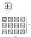
- an FFL is generated by placing two parallel coil pairs (fed with alternating current directions) side by side. Using two of these coil groups, the FFL can be rotated in the plane perpendicular to the coil axes.
- the FFL can be translated in the rotation plane of the FFL using a coil pair placed on the same axis with the other coils. It can also be translated in the perpendicular plane by asymmetrical coil excitation. As all the coils in the system are parallel, the imaged object can be reached from the sides during imaging.
- Coils (1a) and (1b) are fed with the same current direction generating a magnetic field in the z-direction (6).
- Coils (1c) and (1d) are fed with opposite current direction with respect to the (1a-1b) coil pair, generating a magnetic field in the -z direction (7).
- the x (3) and y (4) components of the magnetic field vanish at the middle plane (the plane generated by the x (3) and y (4) axes) of the top (1a, 1c) and bottom (1b, 1d) coils.
- Coil group 2 (2) has a similar configuration with the coil group (1), but is rotated 90 degrees around z-axis (5).
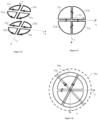
- Fig. 4 the coil system given in Fig. 1 is shown looking into the z-axis (5).
- the FFL can be rotated to any arbitrary angle ⁇ (15) with respect to x-axis (3) on the plane generated by the x (3) and y (4) axes by adjusting the currents of the coil groups (1) and (2).
- (12) shows the direction of the FFL
- the current amplitudes I 1 and I 2 should be arranged such that the magnetic field gradient perpendicular to the FFL axis (14) is independent of the rotation angle (15).
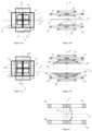
- This coil pair can also be used to enlarge the field of view (16) (imaging space), i.e. as focus field generator. Since the drive magnetic field is parallel to the z-axis (5), the magnetization of the SPIO nanoparticles is also in the z-direction. Therefore, receive coil(s) should be sensitive in the z-direction to obtain the response of the nanoparticles. (13) can also be used as the receiver coil. Alternatively, separate drive field, focus field and receive coils can be used in this axis without violating the open bore requirement.
- Fig. 6b shows the preferred embodiment for which z-axis (5) slice selection is possible with the proposed configuration.
- the amplitude of this alternating current is much smaller than the current required for generating the static (selection field) magnetic field.
- An alternative embodiment is using an external z-drive field coil system similar to the selection field coil system. This embodiment is shown in Fig.7a and 7b looking from the z-axis (5) and x-axis (3) at plane (11), respectively.
- Coil groups (9) and (10) generate the drive field necessary for the FFL scan in the z-axis (5) direction.
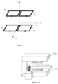
- the drive field transmit unit (34) includes a waveform generator (30a), drive field transmit circuitry (31a), and drive field coil(s) (29a).
- Drive field transmit circuitry (31a) includes components such as amplifier(s), matching circuit(s), filter(s) to supply the required current to generate the drive field.
- the waveform generator (30a) output (amplitude, frequency, waveform, etc.) is controlled by the controlling unit (20) for the required FFL direction and field of view.
- Drive field can be generated by a Helmholtz coil arrangement as given in Fig. 6 and 7 using coils (13a) and (13b).
- (29a) comprises of (13a) and (13b).
- the gradient and linearity of the FFL is not affected from rotation and translation of the FFL, putting a restriction in the coil design.
- the system matrix method a small test object with a known nanoparticle concentration is scanned throughout the FOV volume and the received data is recorded at each position of the object. By this way, a calibration system matrix is generated. The SPIO concentration of the patient/object is obtained using this data.
- the magnetic field of the system can be measured and/or simulated for various rotation angles and translation distances of the FFL, and radon transform can be performed using this data relaxing the need for uniform FFL gradient and linearity throughout the FOV. This method may be more efficient and accurate, since a large system matrix is not required and there is no assumption on the linearity and gradient of the FFL.
- any geometry for the coils can be chosen even though a rectangular geometry is used in this document. In fact, the geometry should be optimized to obtain the best FFL performance with minimum power consumption.
- a coil system in which D type coils (41,42) are used is shown in Figures 12 and 13 .
- the coil system includes two coil groups rotated 90 degrees with respect to each other in the horizontal plane.
- more coil groups e.g. three coil groups rotated 60 degrees with respect to each other
- FIG. 16 An example embodiment using three coil groups (55a, 55b, 55c) rotated 60 degrees with respect to each other in the horizontal plane is shown in Figure 16 .
Landscapes
- Health & Medical Sciences (AREA)
- Physics & Mathematics (AREA)
- Life Sciences & Earth Sciences (AREA)
- Nuclear Medicine, Radiotherapy & Molecular Imaging (AREA)
- Engineering & Computer Science (AREA)
- Condensed Matter Physics & Semiconductors (AREA)
- General Physics & Mathematics (AREA)
- General Health & Medical Sciences (AREA)
- Radiology & Medical Imaging (AREA)
- Surgery (AREA)
- Animal Behavior & Ethology (AREA)
- Pathology (AREA)
- Biomedical Technology (AREA)
- Heart & Thoracic Surgery (AREA)
- Medical Informatics (AREA)
- Molecular Biology (AREA)
- Veterinary Medicine (AREA)
- Biophysics (AREA)
- Public Health (AREA)
- Chemical & Material Sciences (AREA)
- Nanotechnology (AREA)
- Magnetic Resonance Imaging Apparatus (AREA)
- Measurement And Recording Of Electrical Phenomena And Electrical Characteristics Of The Living Body (AREA)
- Signal Processing (AREA)
- High Energy & Nuclear Physics (AREA)
- Vascular Medicine (AREA)
Claims (10)
- Ein System zur Abbildung von Magnetic-Particle-Imaging-System mit offener Bohrung, das Folgendes umfasst:• eine Computersteuerung (20);• eine erste Selektionsfeld-Spulengruppe (21) und eine zweite Selektionsfeld-Spulengruppe (22), wobei die erste Selektionsfeld-Spulengruppe (21) und die zweite Selektionsfeld-Spulengruppe (22) geeignet sind, eine feldlose Linie (FFL) an einer gewünschten z-Achsenposition auf einer Ebene senkrecht zu einer z-Achse (5) zu erzeugen und zu drehen;• wobei sowohl die erste Selektionsfeld-Spulengruppe (21) als auch eine zweite Selektionsfeld-Spulengruppe (22) eine Vielzahl von Stromversorgungen enthält, die jeweils einer Sendeschaltung zugeordnet sind, wobei die Vielzahl von Stromversorgungen und zugeordneten Sendeschaltungen mindestens eine erste Stromversorgung (23a), die einer ersten Sendeschaltung (24a) zugeordnet ist, eine zweite Stromversorgung (23b), die einer zweiten Sendeschaltung (24b) zugeordnet ist, eine dritte Stromversorgung (23c), die einer dritten Sendeschaltung (24c) zugeordnet ist, und eine vierte Stromversorgung (23d), die einer vierten Sendeschaltung (24d) zugeordnet ist, umfasst• wobei die erste Selektionsfeld-Spulengruppe (21) eine erste Selektionsfeldspulengruppe (1) umfasst, wobei die erste Selektionsfeldspulengruppe (1) eine erste Selektionsfeldspule (1a), eine zweite Selektionsfeldspule (1b), eine dritte Selektionsfeldspule (1c) und eine vierte Selektionsfeldspule (1d) umfasst, wobei die erste Selektionsfeldspule (1a), die zweite Selektionsfeldspule (1b), die dritte Selektionsfeldspule (1c) und die vierte Selektionsfeldspule (1d) mit einem jeweiligen ersten Strom (11a), zweiten Strom (I1b), dritten Strom (I1e) und vierten Strom (I1d) gespeist werden;• wobei die zweite Auswahlfeld-Spulengruppe (22) eine zweite Auswahlfeldspulengruppe (2) umfasst, wobei die zweite Auswahlfeldspulengruppe (2) eine erste Auswahlfeldspule (2a), eine zweite Auswahlfeldspule (2b), eine dritte Auswahlfeldspule (2c) und eine vierte Auswahlfeldspule (2d) umfasst, wobei die erste Selektionsfeldspule (2a), die zweite Selektionsfeldspule (2b), die dritte Selektionsfeldspule (2c) und die vierte Selektionsfeldspule (2d) jeweils mit einem ersten Strom (12a), einem zweiten Strom (1212b), einem dritten Strom (12c) und einem vierten Strom (1212d) gespeist werden• wobei die Computersteuerung (20) so ausgelegt ist, dass sie die an die Auswahlfeldspulen (1a, 1b, 1c, 1d, 2a, 2b, 2c, 2d) angelegten Ströme steuert und überwacht,• wobei die erste Auswahlfeldspule (1a) der ersten Auswahlfeldspulengruppe (1) und die dritte Auswahlfeldspule (1c) der ersten Spulengruppe (1) obere Auswahlfeldspulen (25) sind, und die zweite Auswahlfeldspule (1b) der ersten Spulengruppe (1) und die vierte Auswahlfeldspule (1d) der ersten Spulengruppe (1) untere Auswahlfeldspulen (26) sind,• wobei die zweite Auswahlfeldspule (2a) der zweiten Auswahlfeldspulengruppe (2) und die dritte Auswahlfeldspule (2c) der zweiten Spulengruppe (2) obere Auswahlfeldspulen (27) sind, und die zweite Auswahlfeldspule (2b) der zweiten Spulengruppe (2) und die vierte Auswahlfeldspule (2d) der zweiten Spulengruppe (2) untere Auswahlfeldspulen (28) sind,• wobei die Beträge der Ströme in den oberen Auswahlfeldspulen (1a, 1c) der ersten Auswahlfeldspulengruppe (1) gleich sind, während ihre Vorzeichen entgegengesetzt sind, und die Beträge der Ströme in den unteren Auswahlfeldspulen (1b, 1d) der ersten Auswahlfeldspulengruppe (1) gleich sind, während ihre Vorzeichen entgegengesetzt sind (I1a=-1 c, I1b=-11d, 12a=-12c, 12b=-12d),• wobei die erzeugte FFL zwischen oberen und unteren Selektionsfeldspulen erzeugt wird,• wobei alle Spulen in der ersten und zweiten Auswahlfeldspulengruppe parallel sind,• wobei die zweite Spulengruppe (2) um die z-Achse in Bezug auf die erste Spulengruppe (1) mit einer Drehung von 90 Grad gedreht wird,• wobei das System ferner eine erste Antriebsfeld-Spulengruppe (34) umfasst, die einen Wellenformgenerator (30a), eine Antriebsfeld-Sendeschaltung (31a) und eine dritte Spulengruppe (29a) umfasst, die eine obere Spule (13a) und eine untere Spule (13b) umfasst und so beschaffen ist, dass sie die FFL in einer Ebene parallel zu der durch eine x-Achse (3) und eine y-Achse (4) erzeugten Ebene verschiebt/abtastet und die magnetischen Teilchen in einem xy-Antriebsfeld anregt.
- System nach Anspruch 1, wobei jede Selektionsfeldspule (1a, 1b, 1c, 1d, 2a, 2b, 2c, 2d) von einer separaten Stromversorgung gespeist wird.
- System nach Anspruch 1, das ferner eine zweite Antriebsfeld-Spulengruppe (35) umfasst, die so eingerichtet ist, dass sie den FFL auf einer z-Achse (5) verschiebt/abtastet und die magnetischen Teilchen in einem z-Antriebsfeld anregt, und die einen ersten Wellenformgenerator (30b), einen zweiten Wellenformgenerator (30c), eine erste Antriebsfeld-Sendeschaltung (31b), die dem ersten Wellenformgenerator (30b) zugeordnet ist eine zweite Antriebsfeld-Sendeschaltung (31c), die mit dem zweiten Wellenformgenerator (30c) verbunden ist, eine erste Antriebsfeldspule (29b), die mit der ersten Antriebsfeld-Sendeschaltung (31b) verbunden ist, und eine zweite Antriebsfeldspule (29c), die mit der zweiten Antriebsfeld-Sendeschaltung (31c) verbunden ist.
- System nach Anspruch 2 oder 3, wobei die erste Antriebsfeld-Spulengruppe (34) auch ein Fokusfeldgenerator ist, der dazu geeignet ist, ein Zentrum eines Sichtfeldes in der Ebene parallel zu der Ebene zu verschieben, die durch eine x-Achse (3) und eine y-Achse (4) erzeugt wird.
- System nach Anspruch 2 oder 4, wobei mindestens eine der zweiten Antriebsfeld- und/oder Fokusfeldspulen (29a) eine Helmholtz-Spulenanordnung (13a, 13b) umfasst.
- System nach Anspruch 1, umfassend mindestens eine Empfängerspule (32) zum Empfangen der von den SPIOs erzeugten Magnetisierungssignale und eine Empfängerschaltung (33) zum Verstärken, Filtern und Digitalisieren des empfangenen Signals über die Empfängerspule(n) (32).
- System nach Anspruch 1, wobei die Wicklungen der ersten (1) und der zweiten (2) Spulenauswahlfeldgruppe ineinander verschachtelt sind.
- System nach Anspruch 7, bei dem der Verlauf der Spulenwicklungen rechteckig ist.
- System nach Anspruch 7, bei dem der Verlauf der Spulenwicklungen halbkreisförmig ist.
- Spulensystem mit offener Bohrung nach Anspruch 1, wobei zur Drehung des FFL um phi Grad (15) in Bezug auf die x-Achse (3) die Erregung für die Spulen in der ersten Spulenauswahlfeldgruppe (1) 11 a=11 b=-11 c=-11 d =11 cos(phi) und die Erregung der Spulen in der zweiten Spulenauswahlfeldgruppe (2) 12a=12b=- 12c=-12d =12 Sin(phi) ist.
Applications Claiming Priority (2)
| Application Number | Priority Date | Filing Date | Title |
|---|---|---|---|
| US15/435,208 US10478087B2 (en) | 2017-02-16 | 2017-02-16 | Open bore field free line magnetic particle imaging system |
| PCT/TR2018/050038 WO2018222162A2 (en) | 2017-02-16 | 2018-02-02 | Open bore field free line magnetic particle imaging system |
Publications (3)
| Publication Number | Publication Date |
|---|---|
| EP3582687A2 EP3582687A2 (de) | 2019-12-25 |
| EP3582687B1 true EP3582687B1 (de) | 2024-07-24 |
| EP3582687C0 EP3582687C0 (de) | 2024-07-24 |
Family
ID=63105089
Family Applications (1)
| Application Number | Title | Priority Date | Filing Date |
|---|---|---|---|
| EP18793715.6A Active EP3582687B1 (de) | 2017-02-16 | 2018-02-02 | Magnetpartikelbildgebungssystem mit feldfreier linie und offener bohrung |
Country Status (6)
| Country | Link |
|---|---|
| US (1) | US10478087B2 (de) |
| EP (1) | EP3582687B1 (de) |
| JP (1) | JP7004185B2 (de) |
| KR (1) | KR20190117004A (de) |
| CN (1) | CN110573072B (de) |
| WO (1) | WO2018222162A2 (de) |
Families Citing this family (24)
| Publication number | Priority date | Publication date | Assignee | Title |
|---|---|---|---|---|
| EP3545835B1 (de) * | 2018-03-29 | 2022-03-30 | Julius-Maximilians-Universität Würzburg | System und verfahren zur erzeugung einer wandernden feldfreien linie |
| DE102018109505A1 (de) * | 2018-04-20 | 2019-10-24 | Stl Systems Ag | Polyederförmige Spulensysteme mit großem Homogenitätsvolumen und großem Zugangsbereich |
| EP3702796B1 (de) * | 2019-02-28 | 2024-12-25 | Julius-Maximilians-Universität Würzburg | System zur einseitigen erzeugung von magnetfeldern für die mehrdimensionale codierung von magnetpartikeln und verfahren zum betreiben derselben |
| CN110420026B (zh) * | 2019-07-15 | 2020-05-19 | 中国科学院自动化研究所 | 基于ffl的磁粒子成像三维立体重建方法、系统、装置 |
| US11561270B2 (en) * | 2019-08-30 | 2023-01-24 | Electronics And Telecommunications Research Institute | Apparatus and method for nano magnetic particle imaging |
| US11707202B2 (en) * | 2020-09-24 | 2023-07-25 | Electronics And Telecommunications Research Institute | Apparatus for generating field-free region, apparatus and method for nano magnetic particle image |
| KR102508516B1 (ko) * | 2020-10-30 | 2023-03-09 | 광주과학기술원 | 개방형 자기입자영상 장치 |
| KR102743471B1 (ko) * | 2021-02-08 | 2024-12-17 | 광주과학기술원 | 개방형 자기입자영상 기반 나노입자 온열 장치 |
| CN113288106B (zh) * | 2021-05-24 | 2022-11-15 | 中国科学院自动化研究所 | 磁粒子成像检测系统、方法、电子设备 |
| CN113433495B (zh) * | 2021-06-25 | 2022-08-05 | 中国科学院自动化研究所 | 基于阵列式接收线圈的开放式磁粒子三维成像系统及方法 |
| CN113567899A (zh) * | 2021-07-21 | 2021-10-29 | 北京航空航天大学 | 一种基于永磁体旋转扫描的三维磁粒子成像设备及方法 |
| US11733324B2 (en) * | 2021-09-24 | 2023-08-22 | Mitsubishi Electric Corporation | Magnetic particle imaging system and magnetic particle imaging method |
| KR102749998B1 (ko) * | 2022-03-21 | 2025-01-03 | 재단법인 한국마이크로의료로봇연구원 | 자성입자 탐지를 위한 개방형 rf 송수신코일 시스템 |
| CN114521883B (zh) * | 2022-04-22 | 2022-07-19 | 北京航空航天大学 | 闭孔式无场线扫描磁粒子成像装置、系统及方法 |
| CN115054222B (zh) * | 2022-08-18 | 2022-12-27 | 沈阳工业大学 | 机械扫描大空间磁粒子成像设备、成像系统及成像方法 |
| CN115067918B (zh) * | 2022-08-18 | 2022-12-23 | 沈阳工业大学 | 基于ffl的高清度实时成像设备、成像系统及成像方法 |
| CN115067917B (zh) * | 2022-08-18 | 2022-12-23 | 沈阳工业大学 | 一种开放式磁粒子成像设备、成像系统及成像方法 |
| CN115813366B (zh) | 2023-02-06 | 2023-05-16 | 北京航空航天大学 | 一种多线圈手持式磁粒子成像装置、方法及电子设备 |
| CN116520215B (zh) * | 2023-03-21 | 2025-08-15 | 西安电子科技大学 | 一种单边磁粒子成像装置及系统 |
| CN117653070B (zh) * | 2024-01-31 | 2024-05-10 | 北京航空航天大学 | 一种基于多磁场自由线并行扫描的磁粒子成像装置 |
| CN117686954B (zh) * | 2024-02-04 | 2024-05-10 | 北京航空航天大学 | 基于振荡梯度磁场编码的磁粒子成像方法及设备 |
| CN119758202B (zh) * | 2025-03-10 | 2025-06-17 | 北京航空航天大学 | 一种层叠式高均匀性磁场自由线磁粒子成像系统及方法 |
| CN120044457B (zh) * | 2025-04-24 | 2025-08-05 | 北京航空航天大学 | 一种多切片同步扫描的磁粒子成像系统及方法 |
| CN120178124B (zh) * | 2025-05-21 | 2025-09-02 | 北京航空航天大学 | 一种基于柔性接收线圈阵列的磁粒子成像系统及方法 |
Citations (2)
| Publication number | Priority date | Publication date | Assignee | Title |
|---|---|---|---|---|
| US20120126808A1 (en) * | 2009-08-21 | 2012-05-24 | Koninklijke Philips Electronics N.V. | Apparatus and method for generating and moving a magnetic field having a field free line |
| US20140159712A1 (en) * | 2012-12-10 | 2014-06-12 | General Electric Company | Systems and methods for magnetic material imaging |
Family Cites Families (21)
| Publication number | Priority date | Publication date | Assignee | Title |
|---|---|---|---|---|
| US4829252A (en) * | 1987-10-28 | 1989-05-09 | The Regents Of The University Of California | MRI system with open access to patient image volume |
| US5280248A (en) * | 1992-07-24 | 1994-01-18 | Picker International, Inc. | Biplanar RF coil for magnetic resonance imaging systems |
| RU98106937A (ru) * | 1998-04-14 | 2000-02-10 | Пикер Нордстар ОЮ (FI) | Устройство для формирования изображения с помощью магнитного резонанса |
| US6249121B1 (en) * | 1999-05-17 | 2001-06-19 | General Electric Company | RF body coil |
| US6437567B1 (en) * | 1999-12-06 | 2002-08-20 | General Electric Company | Radio frequency coil for open magnetic resonance imaging system |
| JP3842520B2 (ja) * | 2000-04-26 | 2006-11-08 | ジーイー・メディカル・システムズ・グローバル・テクノロジー・カンパニー・エルエルシー | Rfコイルおよび磁気共鳴撮影装置 |
| JP3705996B2 (ja) * | 2000-04-26 | 2005-10-12 | ジーイー・メディカル・システムズ・グローバル・テクノロジー・カンパニー・エルエルシー | 磁気共鳴撮影装置 |
| WO2002042791A1 (en) * | 2000-11-24 | 2002-05-30 | Koninklijke Philips Electronics N.V. | Method for obtaining mri images using sub-sampling in a vertical field mri apparatus |
| US6420871B1 (en) * | 2001-03-02 | 2002-07-16 | Varian, Inc. | Multiple tuned birdcage coils |
| JP3727601B2 (ja) * | 2002-03-05 | 2005-12-14 | ジーイー・メディカル・システムズ・グローバル・テクノロジー・カンパニー・エルエルシー | 磁気共鳴イメージング装置 |
| US6781371B2 (en) * | 2002-09-06 | 2004-08-24 | Schlumberger Technology Corporation | High vertical resolution antennas for NMR logging |
| US7365542B1 (en) * | 2006-10-31 | 2008-04-29 | General Electric Company | Flexible RF coil assembly and method of making same |
| EP2120698A2 (de) | 2006-12-20 | 2009-11-25 | Philips Intellectual Property & Standards GmbH | Anordnung zur beeinflussung und/oder zum nachweis von magnetischen teilchen in einer wirkregion und verfahren zur herstellung einer scheibenförmigen spule |
| JP5238445B2 (ja) * | 2008-10-08 | 2013-07-17 | 株式会社東芝 | 磁性微粒子イメージング装置 |
| BR112012019482A2 (pt) | 2010-02-08 | 2018-07-24 | Koninl Philips Electronics Nv | aparelho para influenciar e\ou detectar partículas magnéticas em um campo de visão, metodo para influenciar e/ou detectar partículas magneticas em um campo de visão e programa de computador |
| KR101551586B1 (ko) * | 2011-08-09 | 2015-09-08 | 히타치 긴조쿠 가부시키가이샤 | 코일 장치 및 자기공명 이메징 장치 |
| EP2755552B1 (de) | 2011-11-16 | 2018-05-16 | Koninklijke Philips N.V. | Vorrichtung zur beeinflussung und/oder erkennung von magnetpartikeln mit einem grossen sichtfeld |
| BR112014014284A2 (pt) | 2011-12-15 | 2017-06-13 | Koninklijke Philips Nv | aparelho e método para detecção de partículas magnéticas em um campo de visão, e, programa de computador |
| US9714990B2 (en) | 2013-03-14 | 2017-07-25 | Electronics And Telecommunications Research Institute | Apparatus for magnetic particle imaging |
| JP2014209680A (ja) | 2013-04-16 | 2014-11-06 | 富士通株式会社 | 土地境界表示プログラム、方法、及び端末装置 |
| US9211083B2 (en) * | 2013-09-12 | 2015-12-15 | General Electric Company | Systems and methods for magnetic material imaging |
-
2017
- 2017-02-16 US US15/435,208 patent/US10478087B2/en active Active
-
2018
- 2018-02-02 KR KR1020197026378A patent/KR20190117004A/ko not_active Ceased
- 2018-02-02 WO PCT/TR2018/050038 patent/WO2018222162A2/en not_active Ceased
- 2018-02-02 CN CN201880020989.9A patent/CN110573072B/zh active Active
- 2018-02-02 JP JP2019543207A patent/JP7004185B2/ja active Active
- 2018-02-02 EP EP18793715.6A patent/EP3582687B1/de active Active
Patent Citations (2)
| Publication number | Priority date | Publication date | Assignee | Title |
|---|---|---|---|---|
| US20120126808A1 (en) * | 2009-08-21 | 2012-05-24 | Koninklijke Philips Electronics N.V. | Apparatus and method for generating and moving a magnetic field having a field free line |
| US20140159712A1 (en) * | 2012-12-10 | 2014-06-12 | General Electric Company | Systems and methods for magnetic material imaging |
Non-Patent Citations (2)
| Title |
|---|
| GAEL BRINGOUT: "Field Free Line Magnetic Particle Imaging Characterisation And Imaging Device Up-Scaling", 20 April 2016 (2016-04-20), XP055540204, Retrieved from the Internet <URL:https://www.researchgate.net/profile/Gael_Bringout2/publication/309352059_Field_Free_Line_Magnetic_Particle_Imaging_Characterisation_And_Imaging_Device_Up-Scaling/links/580a7a3808aecba934f9668e.pdf> [retrieved on 20190110], DOI: 10.5281/zenodo.162417 * |
| JUERGEN WEIZENECKER ET AL: "Magnetic particle imaging using a field free line", JOURNAL OF PHYSICS D: APPLIED PHYSICS, vol. 41, no. 10, 1 May 2008 (2008-05-01), Bristol, GB, pages 105009, XP055540002, ISSN: 0022-3727, DOI: 10.1088/0022-3727/41/10/105009 * |
Also Published As
| Publication number | Publication date |
|---|---|
| KR20190117004A (ko) | 2019-10-15 |
| JP7004185B2 (ja) | 2022-01-21 |
| JP2020508730A (ja) | 2020-03-26 |
| WO2018222162A2 (en) | 2018-12-06 |
| CN110573072B (zh) | 2023-06-09 |
| US10478087B2 (en) | 2019-11-19 |
| EP3582687C0 (de) | 2024-07-24 |
| EP3582687A2 (de) | 2019-12-25 |
| CN110573072A (zh) | 2019-12-13 |
| WO2018222162A3 (en) | 2019-02-07 |
| US20180231629A1 (en) | 2018-08-16 |
Similar Documents
| Publication | Publication Date | Title |
|---|---|---|
| EP3582687B1 (de) | Magnetpartikelbildgebungssystem mit feldfreier linie und offener bohrung | |
| EP2467056B1 (de) | Vorrichtung und verfahren zur erzeugung und bewegung eines magnetfeldes mit feldfreier leitung | |
| Top et al. | Electronically rotated and translated field‐free line generation for open bore magnetic particle imaging | |
| Vogel et al. | Traveling wave magnetic particle imaging | |
| US10261141B2 (en) | Apparatus and methods for spatial encoding of FFL-based MPI devices | |
| US7351194B2 (en) | Arrangement for influencing magnetic particles | |
| JP5993866B2 (ja) | 磁性粒子に影響を及ぼす及び/又は磁性粒子を検出するための装置及び方法 | |
| CN112098912B (zh) | 用于磁共振成像的铁磁增强系统及提供该系统的方法 | |
| JP5172384B2 (ja) | 撮像装置 | |
| Top et al. | Trajectory analysis for field free line magnetic particle imaging | |
| JP6318306B2 (ja) | 磁性粒子に作用し及び/又は該磁性粒子を検出するケーブル布線構造、コイル装置、及び装置 | |
| Pagan et al. | Single-sided magnetic particle imaging device with field-free-line geometry for in vivo imaging applications | |
| CN102573623A (zh) | 用于影响和/或探测磁性颗粒的设备和方法 | |
| US11402444B2 (en) | Arrangement allowing the performance of both magnetic particle imaging and magnetic resonance imaging and a device comprising this arrangement | |
| CN117547242B (zh) | 磁感应断层成像设备 | |
| HK1241468B (zh) | 用於磁共振成像的铁磁增强系统及提供该系统的方法 | |
| JP2006136493A (ja) | 手術用受信コイルおよびこれを用いた磁気共鳴イメージング装置 |
Legal Events
| Date | Code | Title | Description |
|---|---|---|---|
| STAA | Information on the status of an ep patent application or granted ep patent |
Free format text: STATUS: UNKNOWN |
|
| STAA | Information on the status of an ep patent application or granted ep patent |
Free format text: STATUS: THE INTERNATIONAL PUBLICATION HAS BEEN MADE |
|
| PUAI | Public reference made under article 153(3) epc to a published international application that has entered the european phase |
Free format text: ORIGINAL CODE: 0009012 |
|
| STAA | Information on the status of an ep patent application or granted ep patent |
Free format text: STATUS: REQUEST FOR EXAMINATION WAS MADE |
|
| 17P | Request for examination filed |
Effective date: 20190916 |
|
| AK | Designated contracting states |
Kind code of ref document: A2 Designated state(s): AL AT BE BG CH CY CZ DE DK EE ES FI FR GB GR HR HU IE IS IT LI LT LU LV MC MK MT NL NO PL PT RO RS SE SI SK SM TR |
|
| AX | Request for extension of the european patent |
Extension state: BA ME |
|
| DAV | Request for validation of the european patent (deleted) | ||
| DAX | Request for extension of the european patent (deleted) | ||
| STAA | Information on the status of an ep patent application or granted ep patent |
Free format text: STATUS: EXAMINATION IS IN PROGRESS |
|
| 17Q | First examination report despatched |
Effective date: 20220719 |
|
| GRAP | Despatch of communication of intention to grant a patent |
Free format text: ORIGINAL CODE: EPIDOSNIGR1 |
|
| STAA | Information on the status of an ep patent application or granted ep patent |
Free format text: STATUS: GRANT OF PATENT IS INTENDED |
|
| INTG | Intention to grant announced |
Effective date: 20240307 |
|
| RIN1 | Information on inventor provided before grant (corrected) |
Inventor name: GUEVEN, HUESEYIN EMRE Inventor name: TOP, CAN BARIS |
|
| GRAS | Grant fee paid |
Free format text: ORIGINAL CODE: EPIDOSNIGR3 |
|
| GRAA | (expected) grant |
Free format text: ORIGINAL CODE: 0009210 |
|
| STAA | Information on the status of an ep patent application or granted ep patent |
Free format text: STATUS: THE PATENT HAS BEEN GRANTED |
|
| AK | Designated contracting states |
Kind code of ref document: B1 Designated state(s): AL AT BE BG CH CY CZ DE DK EE ES FI FR GB GR HR HU IE IS IT LI LT LU LV MC MK MT NL NO PL PT RO RS SE SI SK SM TR |
|
| REG | Reference to a national code |
Ref country code: GB Ref legal event code: FG4D |
|
| REG | Reference to a national code |
Ref country code: CH Ref legal event code: EP |
|
| REG | Reference to a national code |
Ref country code: DE Ref legal event code: R096 Ref document number: 602018072228 Country of ref document: DE |
|
| REG | Reference to a national code |
Ref country code: IE Ref legal event code: FG4D |
|
| U01 | Request for unitary effect filed |
Effective date: 20240731 |
|
| U07 | Unitary effect registered |
Designated state(s): AT BE BG DE DK EE FI FR IT LT LU LV MT NL PT SE SI Effective date: 20240807 |
|
| PG25 | Lapsed in a contracting state [announced via postgrant information from national office to epo] |
Ref country code: NO Free format text: LAPSE BECAUSE OF FAILURE TO SUBMIT A TRANSLATION OF THE DESCRIPTION OR TO PAY THE FEE WITHIN THE PRESCRIBED TIME-LIMIT Effective date: 20241024 |
|
| PG25 | Lapsed in a contracting state [announced via postgrant information from national office to epo] |
Ref country code: PL Free format text: LAPSE BECAUSE OF FAILURE TO SUBMIT A TRANSLATION OF THE DESCRIPTION OR TO PAY THE FEE WITHIN THE PRESCRIBED TIME-LIMIT Effective date: 20240724 Ref country code: GR Free format text: LAPSE BECAUSE OF FAILURE TO SUBMIT A TRANSLATION OF THE DESCRIPTION OR TO PAY THE FEE WITHIN THE PRESCRIBED TIME-LIMIT Effective date: 20241025 |
|
| PG25 | Lapsed in a contracting state [announced via postgrant information from national office to epo] |
Ref country code: IS Free format text: LAPSE BECAUSE OF FAILURE TO SUBMIT A TRANSLATION OF THE DESCRIPTION OR TO PAY THE FEE WITHIN THE PRESCRIBED TIME-LIMIT Effective date: 20241124 |
|
| PG25 | Lapsed in a contracting state [announced via postgrant information from national office to epo] |
Ref country code: HR Free format text: LAPSE BECAUSE OF FAILURE TO SUBMIT A TRANSLATION OF THE DESCRIPTION OR TO PAY THE FEE WITHIN THE PRESCRIBED TIME-LIMIT Effective date: 20240724 |
|
| PG25 | Lapsed in a contracting state [announced via postgrant information from national office to epo] |
Ref country code: RS Free format text: LAPSE BECAUSE OF FAILURE TO SUBMIT A TRANSLATION OF THE DESCRIPTION OR TO PAY THE FEE WITHIN THE PRESCRIBED TIME-LIMIT Effective date: 20241024 Ref country code: ES Free format text: LAPSE BECAUSE OF FAILURE TO SUBMIT A TRANSLATION OF THE DESCRIPTION OR TO PAY THE FEE WITHIN THE PRESCRIBED TIME-LIMIT Effective date: 20240724 |
|
| PG25 | Lapsed in a contracting state [announced via postgrant information from national office to epo] |
Ref country code: RS Free format text: LAPSE BECAUSE OF FAILURE TO SUBMIT A TRANSLATION OF THE DESCRIPTION OR TO PAY THE FEE WITHIN THE PRESCRIBED TIME-LIMIT Effective date: 20241024 Ref country code: PL Free format text: LAPSE BECAUSE OF FAILURE TO SUBMIT A TRANSLATION OF THE DESCRIPTION OR TO PAY THE FEE WITHIN THE PRESCRIBED TIME-LIMIT Effective date: 20240724 Ref country code: NO Free format text: LAPSE BECAUSE OF FAILURE TO SUBMIT A TRANSLATION OF THE DESCRIPTION OR TO PAY THE FEE WITHIN THE PRESCRIBED TIME-LIMIT Effective date: 20241024 Ref country code: IS Free format text: LAPSE BECAUSE OF FAILURE TO SUBMIT A TRANSLATION OF THE DESCRIPTION OR TO PAY THE FEE WITHIN THE PRESCRIBED TIME-LIMIT Effective date: 20241124 Ref country code: HR Free format text: LAPSE BECAUSE OF FAILURE TO SUBMIT A TRANSLATION OF THE DESCRIPTION OR TO PAY THE FEE WITHIN THE PRESCRIBED TIME-LIMIT Effective date: 20240724 Ref country code: GR Free format text: LAPSE BECAUSE OF FAILURE TO SUBMIT A TRANSLATION OF THE DESCRIPTION OR TO PAY THE FEE WITHIN THE PRESCRIBED TIME-LIMIT Effective date: 20241025 Ref country code: ES Free format text: LAPSE BECAUSE OF FAILURE TO SUBMIT A TRANSLATION OF THE DESCRIPTION OR TO PAY THE FEE WITHIN THE PRESCRIBED TIME-LIMIT Effective date: 20240724 |
|
| U20 | Renewal fee for the european patent with unitary effect paid |
Year of fee payment: 8 Effective date: 20250228 |
|
| PG25 | Lapsed in a contracting state [announced via postgrant information from national office to epo] |
Ref country code: SM Free format text: LAPSE BECAUSE OF FAILURE TO SUBMIT A TRANSLATION OF THE DESCRIPTION OR TO PAY THE FEE WITHIN THE PRESCRIBED TIME-LIMIT Effective date: 20240724 Ref country code: RO Free format text: LAPSE BECAUSE OF FAILURE TO SUBMIT A TRANSLATION OF THE DESCRIPTION OR TO PAY THE FEE WITHIN THE PRESCRIBED TIME-LIMIT Effective date: 20240724 |
|
| PG25 | Lapsed in a contracting state [announced via postgrant information from national office to epo] |
Ref country code: CZ Free format text: LAPSE BECAUSE OF FAILURE TO SUBMIT A TRANSLATION OF THE DESCRIPTION OR TO PAY THE FEE WITHIN THE PRESCRIBED TIME-LIMIT Effective date: 20240724 |
|
| PG25 | Lapsed in a contracting state [announced via postgrant information from national office to epo] |
Ref country code: SK Free format text: LAPSE BECAUSE OF FAILURE TO SUBMIT A TRANSLATION OF THE DESCRIPTION OR TO PAY THE FEE WITHIN THE PRESCRIBED TIME-LIMIT Effective date: 20240724 |
|
| PLBE | No opposition filed within time limit |
Free format text: ORIGINAL CODE: 0009261 |
|
| STAA | Information on the status of an ep patent application or granted ep patent |
Free format text: STATUS: NO OPPOSITION FILED WITHIN TIME LIMIT |
|
| 26N | No opposition filed |
Effective date: 20250425 |
|
| PG25 | Lapsed in a contracting state [announced via postgrant information from national office to epo] |
Ref country code: MC Free format text: LAPSE BECAUSE OF FAILURE TO SUBMIT A TRANSLATION OF THE DESCRIPTION OR TO PAY THE FEE WITHIN THE PRESCRIBED TIME-LIMIT Effective date: 20240724 |
|
| REG | Reference to a national code |
Ref country code: CH Ref legal event code: PL |
|
| PG25 | Lapsed in a contracting state [announced via postgrant information from national office to epo] |
Ref country code: CH Free format text: LAPSE BECAUSE OF NON-PAYMENT OF DUE FEES Effective date: 20250228 |
|
| GBPC | Gb: european patent ceased through non-payment of renewal fee |
Effective date: 20250202 |
|
| PG25 | Lapsed in a contracting state [announced via postgrant information from national office to epo] |
Ref country code: GB Free format text: LAPSE BECAUSE OF NON-PAYMENT OF DUE FEES Effective date: 20250202 |
|
| PG25 | Lapsed in a contracting state [announced via postgrant information from national office to epo] |
Ref country code: IE Free format text: LAPSE BECAUSE OF NON-PAYMENT OF DUE FEES Effective date: 20250202 |