EP3582497A1 - Dispositif de traitement d'images et procédé de traitement d'images - Google Patents
Dispositif de traitement d'images et procédé de traitement d'images Download PDFInfo
- Publication number
- EP3582497A1 EP3582497A1 EP19186698.7A EP19186698A EP3582497A1 EP 3582497 A1 EP3582497 A1 EP 3582497A1 EP 19186698 A EP19186698 A EP 19186698A EP 3582497 A1 EP3582497 A1 EP 3582497A1
- Authority
- EP
- European Patent Office
- Prior art keywords
- horizontal
- vertical
- section
- filtering
- boundaries
- Prior art date
- Legal status (The legal status is an assumption and is not a legal conclusion. Google has not performed a legal analysis and makes no representation as to the accuracy of the status listed.)
- Pending
Links
- 238000012545 processing Methods 0.000 title claims abstract description 160
- 238000003672 processing method Methods 0.000 title claims description 16
- 238000001914 filtration Methods 0.000 claims abstract description 452
- 238000000034 method Methods 0.000 claims description 416
- 230000008569 process Effects 0.000 claims description 359
- 238000010586 diagram Methods 0.000 description 68
- 238000004364 calculation method Methods 0.000 description 33
- 241000023320 Luma <angiosperm> Species 0.000 description 22
- 238000004891 communication Methods 0.000 description 22
- OSWPMRLSEDHDFF-UHFFFAOYSA-N methyl salicylate Chemical compound COC(=O)C1=CC=CC=C1O OSWPMRLSEDHDFF-UHFFFAOYSA-N 0.000 description 22
- 238000013139 quantization Methods 0.000 description 21
- 230000005540 biological transmission Effects 0.000 description 18
- 230000006870 function Effects 0.000 description 15
- 230000005236 sound signal Effects 0.000 description 12
- 238000009825 accumulation Methods 0.000 description 11
- 238000005516 engineering process Methods 0.000 description 10
- 238000011156 evaluation Methods 0.000 description 10
- 230000003287 optical effect Effects 0.000 description 10
- 238000006243 chemical reaction Methods 0.000 description 9
- 230000004048 modification Effects 0.000 description 8
- 238000012986 modification Methods 0.000 description 8
- 230000000694 effects Effects 0.000 description 6
- 101000974007 Homo sapiens Nucleosome assembly protein 1-like 3 Proteins 0.000 description 5
- 102100022398 Nucleosome assembly protein 1-like 3 Human genes 0.000 description 5
- 230000015556 catabolic process Effects 0.000 description 4
- 238000006731 degradation reaction Methods 0.000 description 4
- 238000009434 installation Methods 0.000 description 4
- 230000004913 activation Effects 0.000 description 3
- 238000012937 correction Methods 0.000 description 3
- 239000000284 extract Substances 0.000 description 3
- 230000008859 change Effects 0.000 description 2
- 230000006835 compression Effects 0.000 description 2
- 238000007906 compression Methods 0.000 description 2
- 230000003247 decreasing effect Effects 0.000 description 2
- 230000014509 gene expression Effects 0.000 description 2
- 239000004065 semiconductor Substances 0.000 description 2
- 230000003321 amplification Effects 0.000 description 1
- 230000010267 cellular communication Effects 0.000 description 1
- 210000003127 knee Anatomy 0.000 description 1
- 239000004973 liquid crystal related substance Substances 0.000 description 1
- 230000007246 mechanism Effects 0.000 description 1
- 238000003199 nucleic acid amplification method Methods 0.000 description 1
- 238000007639 printing Methods 0.000 description 1
- 238000004904 shortening Methods 0.000 description 1
- 239000007787 solid Substances 0.000 description 1
- 230000009466 transformation Effects 0.000 description 1
- 238000011426 transformation method Methods 0.000 description 1
Images


Classifications
-
- H—ELECTRICITY
- H04—ELECTRIC COMMUNICATION TECHNIQUE
- H04N—PICTORIAL COMMUNICATION, e.g. TELEVISION
- H04N19/00—Methods or arrangements for coding, decoding, compressing or decompressing digital video signals
- H04N19/10—Methods or arrangements for coding, decoding, compressing or decompressing digital video signals using adaptive coding
- H04N19/102—Methods or arrangements for coding, decoding, compressing or decompressing digital video signals using adaptive coding characterised by the element, parameter or selection affected or controlled by the adaptive coding
- H04N19/117—Filters, e.g. for pre-processing or post-processing
-
- H—ELECTRICITY
- H04—ELECTRIC COMMUNICATION TECHNIQUE
- H04N—PICTORIAL COMMUNICATION, e.g. TELEVISION
- H04N19/00—Methods or arrangements for coding, decoding, compressing or decompressing digital video signals
- H04N19/10—Methods or arrangements for coding, decoding, compressing or decompressing digital video signals using adaptive coding
- H04N19/102—Methods or arrangements for coding, decoding, compressing or decompressing digital video signals using adaptive coding characterised by the element, parameter or selection affected or controlled by the adaptive coding
- H04N19/119—Adaptive subdivision aspects, e.g. subdivision of a picture into rectangular or non-rectangular coding blocks
-
- H—ELECTRICITY
- H04—ELECTRIC COMMUNICATION TECHNIQUE
- H04N—PICTORIAL COMMUNICATION, e.g. TELEVISION
- H04N19/00—Methods or arrangements for coding, decoding, compressing or decompressing digital video signals
- H04N19/10—Methods or arrangements for coding, decoding, compressing or decompressing digital video signals using adaptive coding
- H04N19/102—Methods or arrangements for coding, decoding, compressing or decompressing digital video signals using adaptive coding characterised by the element, parameter or selection affected or controlled by the adaptive coding
- H04N19/12—Selection from among a plurality of transforms or standards, e.g. selection between discrete cosine transform [DCT] and sub-band transform or selection between H.263 and H.264
- H04N19/122—Selection of transform size, e.g. 8x8 or 2x4x8 DCT; Selection of sub-band transforms of varying structure or type
-
- H—ELECTRICITY
- H04—ELECTRIC COMMUNICATION TECHNIQUE
- H04N—PICTORIAL COMMUNICATION, e.g. TELEVISION
- H04N19/00—Methods or arrangements for coding, decoding, compressing or decompressing digital video signals
- H04N19/10—Methods or arrangements for coding, decoding, compressing or decompressing digital video signals using adaptive coding
- H04N19/102—Methods or arrangements for coding, decoding, compressing or decompressing digital video signals using adaptive coding characterised by the element, parameter or selection affected or controlled by the adaptive coding
- H04N19/124—Quantisation
-
- H—ELECTRICITY
- H04—ELECTRIC COMMUNICATION TECHNIQUE
- H04N—PICTORIAL COMMUNICATION, e.g. TELEVISION
- H04N19/00—Methods or arrangements for coding, decoding, compressing or decompressing digital video signals
- H04N19/10—Methods or arrangements for coding, decoding, compressing or decompressing digital video signals using adaptive coding
- H04N19/102—Methods or arrangements for coding, decoding, compressing or decompressing digital video signals using adaptive coding characterised by the element, parameter or selection affected or controlled by the adaptive coding
- H04N19/13—Adaptive entropy coding, e.g. adaptive variable length coding [AVLC] or context adaptive binary arithmetic coding [CABAC]
-
- H—ELECTRICITY
- H04—ELECTRIC COMMUNICATION TECHNIQUE
- H04N—PICTORIAL COMMUNICATION, e.g. TELEVISION
- H04N19/00—Methods or arrangements for coding, decoding, compressing or decompressing digital video signals
- H04N19/10—Methods or arrangements for coding, decoding, compressing or decompressing digital video signals using adaptive coding
- H04N19/169—Methods or arrangements for coding, decoding, compressing or decompressing digital video signals using adaptive coding characterised by the coding unit, i.e. the structural portion or semantic portion of the video signal being the object or the subject of the adaptive coding
- H04N19/17—Methods or arrangements for coding, decoding, compressing or decompressing digital video signals using adaptive coding characterised by the coding unit, i.e. the structural portion or semantic portion of the video signal being the object or the subject of the adaptive coding the unit being an image region, e.g. an object
- H04N19/172—Methods or arrangements for coding, decoding, compressing or decompressing digital video signals using adaptive coding characterised by the coding unit, i.e. the structural portion or semantic portion of the video signal being the object or the subject of the adaptive coding the unit being an image region, e.g. an object the region being a picture, frame or field
-
- H—ELECTRICITY
- H04—ELECTRIC COMMUNICATION TECHNIQUE
- H04N—PICTORIAL COMMUNICATION, e.g. TELEVISION
- H04N19/00—Methods or arrangements for coding, decoding, compressing or decompressing digital video signals
- H04N19/10—Methods or arrangements for coding, decoding, compressing or decompressing digital video signals using adaptive coding
- H04N19/169—Methods or arrangements for coding, decoding, compressing or decompressing digital video signals using adaptive coding characterised by the coding unit, i.e. the structural portion or semantic portion of the video signal being the object or the subject of the adaptive coding
- H04N19/17—Methods or arrangements for coding, decoding, compressing or decompressing digital video signals using adaptive coding characterised by the coding unit, i.e. the structural portion or semantic portion of the video signal being the object or the subject of the adaptive coding the unit being an image region, e.g. an object
- H04N19/176—Methods or arrangements for coding, decoding, compressing or decompressing digital video signals using adaptive coding characterised by the coding unit, i.e. the structural portion or semantic portion of the video signal being the object or the subject of the adaptive coding the unit being an image region, e.g. an object the region being a block, e.g. a macroblock
-
- H—ELECTRICITY
- H04—ELECTRIC COMMUNICATION TECHNIQUE
- H04N—PICTORIAL COMMUNICATION, e.g. TELEVISION
- H04N19/00—Methods or arrangements for coding, decoding, compressing or decompressing digital video signals
- H04N19/10—Methods or arrangements for coding, decoding, compressing or decompressing digital video signals using adaptive coding
- H04N19/169—Methods or arrangements for coding, decoding, compressing or decompressing digital video signals using adaptive coding characterised by the coding unit, i.e. the structural portion or semantic portion of the video signal being the object or the subject of the adaptive coding
- H04N19/182—Methods or arrangements for coding, decoding, compressing or decompressing digital video signals using adaptive coding characterised by the coding unit, i.e. the structural portion or semantic portion of the video signal being the object or the subject of the adaptive coding the unit being a pixel
-
- H—ELECTRICITY
- H04—ELECTRIC COMMUNICATION TECHNIQUE
- H04N—PICTORIAL COMMUNICATION, e.g. TELEVISION
- H04N19/00—Methods or arrangements for coding, decoding, compressing or decompressing digital video signals
- H04N19/42—Methods or arrangements for coding, decoding, compressing or decompressing digital video signals characterised by implementation details or hardware specially adapted for video compression or decompression, e.g. dedicated software implementation
- H04N19/436—Methods or arrangements for coding, decoding, compressing or decompressing digital video signals characterised by implementation details or hardware specially adapted for video compression or decompression, e.g. dedicated software implementation using parallelised computational arrangements
-
- H—ELECTRICITY
- H04—ELECTRIC COMMUNICATION TECHNIQUE
- H04N—PICTORIAL COMMUNICATION, e.g. TELEVISION
- H04N19/00—Methods or arrangements for coding, decoding, compressing or decompressing digital video signals
- H04N19/50—Methods or arrangements for coding, decoding, compressing or decompressing digital video signals using predictive coding
- H04N19/597—Methods or arrangements for coding, decoding, compressing or decompressing digital video signals using predictive coding specially adapted for multi-view video sequence encoding
-
- H—ELECTRICITY
- H04—ELECTRIC COMMUNICATION TECHNIQUE
- H04N—PICTORIAL COMMUNICATION, e.g. TELEVISION
- H04N19/00—Methods or arrangements for coding, decoding, compressing or decompressing digital video signals
- H04N19/60—Methods or arrangements for coding, decoding, compressing or decompressing digital video signals using transform coding
- H04N19/61—Methods or arrangements for coding, decoding, compressing or decompressing digital video signals using transform coding in combination with predictive coding
-
- H—ELECTRICITY
- H04—ELECTRIC COMMUNICATION TECHNIQUE
- H04N—PICTORIAL COMMUNICATION, e.g. TELEVISION
- H04N19/00—Methods or arrangements for coding, decoding, compressing or decompressing digital video signals
- H04N19/80—Details of filtering operations specially adapted for video compression, e.g. for pixel interpolation
-
- H—ELECTRICITY
- H04—ELECTRIC COMMUNICATION TECHNIQUE
- H04N—PICTORIAL COMMUNICATION, e.g. TELEVISION
- H04N19/00—Methods or arrangements for coding, decoding, compressing or decompressing digital video signals
- H04N19/85—Methods or arrangements for coding, decoding, compressing or decompressing digital video signals using pre-processing or post-processing specially adapted for video compression
- H04N19/86—Methods or arrangements for coding, decoding, compressing or decompressing digital video signals using pre-processing or post-processing specially adapted for video compression involving reduction of coding artifacts, e.g. of blockiness
Definitions
- the present disclosure relates to an image processing device and an image processing method.
- H.264/AVC one of standard specifications for image encoding scheme, applies a deblocking filter to a block boundary in units of blocks each containing 4 ⁇ 4 pixels, for example, in order to prevent image quality degradation due to block distortion while an image is encoded.
- the deblocking filter requires a large amount of processing and may account for 50% of the entire processing amount in image decoding, for example.
- JCTVC-A119 High Efficiency Video Coding
- Non-Patent Literature 1 K.Ugur (Nokia), K.R.Andersson (LM Ericsson), A.Fuldseth (Tandberg Telecom), "JCTVC-A119:Video coding technology proposal by Tandberg, Nokia, and Ericsson", Documents of the first meeting of the Joint Collaborative Team on Video Coding (JCT-VC), Dresden, Germany, 15-23 April, 2010 .
- JCT-VC Joint Collaborative Team on Video Coding
- JCTVC-A119 Even if the technique proposed in JCTVC-A119 is used, there remains dependency between a process on the vertical block boundary and a process on the horizontal block boundary. Specifically, a process on the vertical boundary for one macro block waits until a process on the horizontal boundary for a neighboring macro block is performed. A process on the horizontal boundary for one macro block waits until a process on the vertical boundary for the same macro block is performed.
- the above-described technique can just provide a parallel process of the deblocking filter to a very limited extent. Accordingly, the above-described technique may not successfully solve problems of a delay and a decrease in data rates due to a large processing amount while the deblocking filter is applied.
- the technology according to the disclosure aims at providing an image processing device and an image processing method capable of providing further parallel processing when a deblocking filter is applied.
- an image processing device including a decoding section configured to decode an image from an encoded stream, a horizontal filtering section configured to apply a deblocking filter to a vertical block boundary within an image to be decoded by the decoding section, a vertical filtering section configured to apply a deblocking filter to a horizontal block boundary within an image to be decoded by the decoding section, and a control section configured to cause the horizontal filtering section to filter in parallel a plurality of vertical block boundaries included in a processing unit containing a plurality of coding units and cause the vertical filtering section to filter in parallel a plurality of horizontal block boundaries included in the processing unit.
- the image processing device can be realized typically as an image decoding device for decoding an image.
- an image processing method including decoding an image from an encoded stream, performing horizontal filtering to apply a deblocking filter to a vertical block boundary within an image to be decoded, performing vertical filtering to apply a deblocking filter to a horizontal block boundary within an image to be decoded, and controlling the horizontal filtering and the vertical filtering so as to filter in parallel a plurality of vertical block boundaries included in a processing unit containing a plurality of coding units and filter in parallel a plurality of horizontal block boundaries included in the processing unit.
- an image processing device including a horizontal filtering section configured to apply a deblocking filter to a vertical block boundary within an image to be locally decoded when encoding an image to be encoded, a vertical filtering section configured to apply a deblocking filter to a horizontal block boundary within the image, a control section configured to cause the horizontal filtering section to filter in parallel a plurality of vertical block boundaries included in a processing unit containing a plurality of coding units and cause the vertical filtering section to filter in parallel a plurality of horizontal block boundaries included in the processing unit, and an encoding section configured to encode the image to be encoded using an image filtered by the horizontal filtering section and the vertical filtering section.
- the image processing device can be realized typically as an image encoding device for encoding an image.
- an image processing method including performing horizontal filtering to apply a deblocking filter to a vertical block boundary within an image to be locally decoded when encoding an image to be encoded, performing vertical filtering to apply a deblocking filter to a horizontal block boundary within the image, controlling the horizontal filtering and the vertical filtering so as to filter in parallel a plurality of vertical block boundaries included in a processing unit containing a plurality of coding units and filter in parallel a plurality of horizontal block boundaries included in the processing unit, and encoding the image to be encoded using an image filtered by the horizontal filtering and the vertical filtering.
- the image processing device and the image processing method according to the present disclosure further improves parallel processing when a deblocking filter is applied.
- Figs. 1 and 2 With reference to Figs. 1 and 2 , the following describes an overview of an apparatus to which the technology disclosed in this specification is applicable.
- the technology disclosed in this specification is applicable to an image encoding device and an image decoding device, for example.
- Fig. 1 is a block diagram showing an example of a configuration of an image encoding device 10 according to an embodiment.
- the image encoding device 10 includes an A/D (Analogue to Digital) conversion section 11, a reordering buffer 12, a subtraction section 13, an orthogonal transform section 14, a quantization section 15, a lossless encoding section 16, an accumulation buffer 17, a rate control section 18, an inverse quantization section 21, an inverse orthogonal transform section 22, an addition section 23, a deblocking filter 24a, a frame memory 25, a selector 26, an intra prediction section 30, a motion estimation section 40, and a mode selection section 50.
- A/D Analogue to Digital
- the A/D conversion section 11 converts an image signal input in an analogue format into image data in a digital format, and outputs a series of digital image data to the reordering buffer 12.
- the reordering buffer 12 reorders the images included in the series of image data input from the A/D conversion section 11. After reordering the images according to the a GOP (Group of Pictures) structure according to the encoding process, the reordering buffer 12 outputs the image data which has been reordered to the subtraction section 13, the intra prediction section 30, and the motion estimation section 40.
- GOP Group of Pictures
- the image data input from the reordering buffer 12 and predicted image data selected by the mode selection section 50 described later are supplied to the subtraction section 13.
- the subtraction section 13 calculates predicted error data which is a difference between the image data input from the reordering buffer 12 and the predicted image data input from the mode selection section 50, and outputs the calculated predicted error data to the orthogonal transform section 14.
- the orthogonal transform section 14 performs orthogonal transform on the predicted error data input from the subtraction section 13.
- the orthogonal transform to be performed by the orthogonal transform section 14 may be discrete cosine transform (DCT) or Karhunen-Loeve transform, for example.
- the orthogonal transform section 14 outputs transform coefficient data acquired by the orthogonal transform process to the quantization section 15.
- the transform coefficient data input from the orthogonal transform section 14 and a rate control signal from the rate control section 18 described later are supplied to the quantization section 15.
- the quantization section 15 quantizes the transform coefficient data, and outputs the transform coefficient data which has been quantized (hereinafter, referred to as quantized data) to the lossless encoding section 16 and the inverse quantization section 21. Also, the quantization section 15 switches a quantization parameter (a quantization scale) based on the rate control signal from the rate control section 18 to thereby change the bit rate of the quantized data to be input to the lossless encoding section 16.
- the quantized data input from the quantization section 15 and information described later about intra prediction or inter prediction generated by the intra prediction section 30 or the motion estimation section 40 and selected by the mode selection section 50 are supplied to the lossless encoding section 16.
- the information about intra prediction may include prediction mode information indicating an optimal intra prediction mode for each block, for example.
- the information about inter prediction may include prediction mode information for prediction of a motion vector for each block, difference motion vector information, reference image information, and the like, for example.
- the lossless encoding section 16 generates an encoded stream by performing a lossless encoding process on the quantized data.
- the lossless encoding by the lossless encoding section 16 may be variable-length coding or arithmetic coding, for example.
- the lossless encoding section 16 multiplexes the information about intra prediction or the information about inter prediction mentioned above to the header of the encoded stream (for example, a block header, a slice header or the like). Then, the lossless encoding section 16 outputs the generated encoded stream to the accumulation buffer 17.
- the accumulation buffer 17 temporarily stores the encoded stream input from the lossless encoding section 16 using a storage medium, such as a semiconductor memory. Then, the accumulation buffer 17 outputs the accumulated encoded stream at a rate according to the band of a transmission line (or an output line from the image encoding device 10).
- the rate control section 18 monitors the free space of the accumulation buffer 17. Then, the rate control section 18 generates a rate control signal according to the free space on the accumulation buffer 17, and outputs the generated rate control signal to the quantization section 15. For example, when there is not much free space on the accumulation buffer 17, the rate control section 18 generates a rate control signal for lowering the bit rate of the quantized data. Also, for example, when the free space on the accumulation buffer 17 is sufficiently large, the rate control section 18 generates a rate control signal for increasing the bit rate of the quantized data.
- the inverse quantization section 21 performs an inverse quantization process on the quantized data input from the quantization section 15. Then, the inverse quantization section 21 outputs transform coefficient data acquired by the inverse quantization process to the inverse orthogonal transform section 22.
- the inverse orthogonal transform section 22 performs an inverse orthogonal transform process on the transform coefficient data input from the inverse quantization section 21 to thereby restore the predicted error data. Then, the inverse orthogonal transform section 22 outputs the restored predicted error data to the addition section 23.
- the addition section 23 adds the restored predicted error data input from the inverse orthogonal transform section 22 and the predicted image data input from the mode selection section 50 to thereby generate decoded image data. Then, the addition section 23 outputs the generated decoded image data to the deblocking filter 24a and the frame memory 25.
- a deblocking filter 24a performs filtering processes to decrease block distortion that occurs during image encoding. For example, the deblocking filter 24a determines necessity of filtering for each block boundary of decoded image data supplied from an addition section 23 and applies the deblocking filter to a boundary that is determined to require the filter. The deblocking filter 24a is also supplied with information used for the determination of filtering necessity (e.g., mode information, transform coefficient information, and motion vector information) as well as decoded image data from the addition section 23. After the filtering, the block distortion is eliminated from the decoded image data and the deblocking filter 24a outputs the decoded image data to frame memory 25. The process for the deblocking filter 24a will be described in detail later.
- the frame memory 25 stores, using a storage medium, the decoded image data input from the addition section 23 and the decoded image data after filtering input from the deblocking filter 24a.
- the selector 26 reads, from the frame memory 25, the decoded image data before filtering that is to be used for the intra prediction, and supplies the decoded image data which has been read to the intra prediction section 30 as reference image data. Also, the selector 26 reads, from the frame memory 25, the decoded image data after filtering to be used for the inter prediction, and supplies the decoded image data which has been read to the motion estimation section 40 as reference image data.
- the intra prediction section 30 performs an intra prediction process in each intra prediction mode, based on the image data to be encoded that is input from the reordering buffer 12 and the decoded image data supplied via the selector 26. For example, the intra prediction section 30 evaluates the prediction result of each intra prediction mode using a predetermined cost function. Then, the intra prediction section 30 selects an intra prediction mode by which the cost function value is the smallest, that is, an intra prediction mode by which the compression ratio is the highest, as the optimal intra prediction mode. Furthermore, the intra prediction section 30 outputs, to the mode selection section 50, prediction mode information indicating the optimal intra prediction mode, the predicted image data, and the information about intra prediction such as the cost function value.
- a motion estimation section 40 performs an inter prediction process (prediction process between frames) based on image data for encoding supplied from a reordering buffer 12 and decoded image data supplied via a selector 26. For example, the motion estimation section 40 evaluates the prediction result of each prediction mode using a predetermined cost function. Then, the motion estimation section 40 selects an optimal prediction mode, namely, a prediction mode that minimizes the cost function value or maximizes the compression ratio. The motion estimation section 40 generates predicted image data according to the optimal prediction mode. The motion estimation section 40 outputs information about the inter prediction such as prediction mode information indicating the optimal intra prediction mode, the predicted image data, and the cost function value to a mode selection section 50.
- prediction mode information indicating the optimal intra prediction mode, the predicted image data, and the cost function value
- the mode selection section 50 compares the cost function value related to the intra prediction input from the intra prediction section 30 and the cost function value related to the inter prediction input from the motion estimation section 40. Then, the mode selection section 50 selects a prediction method with a smaller cost function value, from the intra prediction and the inter prediction. In the case of selecting the intra prediction, the mode selection section 50 outputs the information about intra prediction to the lossless encoding section 16, and also, outputs the predicted image data to the subtraction section 13 and the addition section 23. Also, in the case of selecting the inter prediction, the mode selection section 50 outputs the information about inter prediction described above to the lossless encoding section 16, and also, outputs the predicted image data to the subtraction section 13 and the addition section 23.
- Fig. 2 is a block diagram showing an example of a configuration of an image decoding device 60 according to an embodiment.
- the image decoding device 60 includes an accumulation buffer 61, a lossless decoding section 62, an inverse quantization section 63, an inverse orthogonal transform section 64, an addition section 65, a deblocking filter 24b, a reordering buffer 67, a D/A (Digital to Analogue) conversion section 68, a frame memory 69, selectors 70 and 71, an intra prediction section 80, and a motion compensation section 90.
- D/A Digital to Analogue
- the accumulation buffer 61 temporarily stores an encoded stream input via a transmission line using a storage medium.
- the lossless decoding section 62 decodes an encoded stream input from the accumulation buffer 61 according to the encoding method used at the time of encoding. Also, the lossless decoding section 62 decodes information multiplexed to the header region of the encoded stream. Information that is multiplexed to the header region of the encoded stream may include information about intra prediction and information about inter prediction in the block header, for example. The lossless decoding section 62 outputs the information about intra prediction to the intra prediction section 80. Also, the lossless decoding section 62 outputs the information about inter prediction to the motion compensation section 90.
- the inverse quantization section 63 inversely quantizes quantized data which has been decoded by the lossless decoding section 62.
- the inverse orthogonal transform section 64 generates predicted error data by performing inverse orthogonal transformation on transform coefficient data input from the inverse quantization section 63 according to the orthogonal transformation method used at the time of encoding. Then, the inverse orthogonal transform section 64 outputs the generated predicted error data to the addition section 65.
- the addition section 65 adds the predicted error data input from the inverse orthogonal transform section 64 and predicted image data input from the selector 71 to thereby generate decoded image data. Then, the addition section 65 outputs the generated decoded image data to the deblocking filter 24b and the frame memory 69.
- the deblocking filter 24b performs filtering processes to decrease block distortion appearing on a decoded image.
- the deblocking filter 24b determines the necessity of filtering at each block boundary for decoded image data input from the addition section 65, for example, and applies the deblocking filter to a boundary that is determined to require the filter.
- the deblocking filter 24b is also supplied with information used for the determination of filtering necessity as well as decoded image data from the addition section 65. After the filtering, the block distortion is eliminated from the decoded image data and the deblocking filter 24b outputs the decoded image data to the reordering buffer 67 and the frame memory 69. The process for the deblocking filter 24b will be described in detail later.
- the reordering buffer 67 generates a series of image data in a time sequence by reordering images input from the deblocking filter 24b. Then, the reordering buffer 67 outputs the generated image data to the D/A conversion section 68.
- the D/A conversion section 68 converts the image data in a digital format input from the reordering buffer 67 into an image signal in an analogue format. Then, the D/A conversion section 68 causes an image to be displayed by outputting the analogue image signal to a display (not shown) connected to the image decoding device 60, for example.
- the frame memory 69 uses a storage medium to store the decoded image data input from the addition section 65 before filtering and the decoded image data input from the deblocking filter 24b after filtering.
- the selector 70 switches the output destination of the image data from the frame memory 69 between the intra prediction section 80 and the motion compensation section 90 for each block in the image according to mode information acquired by the lossless decoding section 62.
- the selector 70 outputs the decoded image data before filtering that is supplied from the frame memory 69 to the intra prediction section 80 as reference image data.
- the selector 70 outputs the decoded image data after filtering that is supplied from the frame memory 69 to the motion compensation section 90 as the reference image data.
- the selector 71 switches the output source of predicted image data to be supplied to the addition section 65 between the intra prediction section 80 and the motion compensation section 90 for each block in the image according to the mode information acquired by the lossless decoding section 62.
- the selector 71 supplies to the addition section 65 the predicted image data output from the intra prediction section 80.
- the selector 71 supplies to the addition section 65 the predicted image data output from the motion compensation section 90.
- the intra prediction section 80 performs in-screen prediction of a pixel value based on the information about intra prediction input from the lossless decoding section 62 and the reference image data from the frame memory 69, and generates predicted image data. Then, the intra prediction section 80 outputs the generated predicted image data to the selector 71.
- the motion compensation section 90 performs a motion compensation process based on the information about inter prediction input from the lossless decoding section 62 and the reference image data from the frame memory 69, and generates predicted image data. Then, the motion compensation section 90 outputs the generated predicted image data to the selector 71.
- processes using the deblocking filter in an existing image encoding scheme such as H.264/AVC or HEVC include two types of processes, namely, filtering need determination processes and filtering processes. The following describes these two processes in HEVC, for example.
- the filtering need determination processes determine whether the deblocking filter needs to be applied to each boundary of blocks within an input image.
- Block boundaries include a vertical boundary between blocks horizontally adjacent to each other and a horizontal boundary between blocks vertically adjacent to each other.
- JCTVC-A119 uses a block size of 8 ⁇ 8 pixels as a minimum processing unit.
- a macro block of 16 ⁇ 16 pixels includes four blocks of 8 ⁇ 8 pixels.
- the process is applied to one (left) vertical boundary and one (top) horizontal boundary for each block, namely, four boundaries plus four boundaries equal to eight boundaries in total.
- the specification assumes that the macro block as a technical term includes an coding unit (CU) in the context of HEVC.
- CU coding unit
- Fig. 3 is an explanatory diagram showing an example of pixels in two blocks (neighboring blocks) Ba and Bb adjacent to each other around a boundary.
- the following describes the vertical boundary as an example and the description is obviously applicable to the horizontal boundary.
- the example in Fig. 3 uses symbol p ij to represent a pixel in block Ba.
- i denotes a column index
- j denotes a row index.
- the column index i is numbered as 0, 1, 2, and 3 in order (from right to left) from the column nearest to the vertical boundary.
- the row index j is numbered as 0, 1, 2,..., 7 from the top to the bottom.
- the left half of block Ba is omitted from the drawing.
- q kj is used to represent a pixel in block Bb.
- k denotes a column index
- j denotes a row index.
- the column index k is numbered as 0, 1, 2, and 3 in order (from left to right) from the column nearest to the vertical boundary.
- the right half of block Bb is omitted from the drawing.
- the following conditions can be used to determine the necessity of applying the deblocking filter to the vertical boundary between blocks Ba and Bb shown in Fig. 3 .
- the deblocking filter is applied if conditions A and B are both true.
- Condition A3 assumes a motion vector for block Ba to be (MVAx,MVAy) and a motion vector for block Bb to be (MVBx,MVBy) according to the Qpel (1/4 pixel) accuracy.
- Condition B uses ⁇ as an edge determination threshold value. An initial value of ⁇ is given according to a quantization parameter. The value for ⁇ is user-specifiable using a parameter within the slice header.
- Determination condition of chroma component (Chroma) ...
- the deblocking filter is applied if condition A1 is true.
- Condition A1 Block Ba or Bb enters the intra prediction mode.
- the filtering need determination processes on general vertical boundaries (particularly under determination condition B of luma component) reference pixels on the third and sixth rows (assuming the top row to be the first) in each block.
- the filtering need determination processes on horizontal boundaries reference pixels (not shown in Fig. 4 ) on the third and sixth columns in each block. The above-described determination conditions are used to determine that the deblocking filter needs to be applied to a boundary on which the filtering processes described below are performed.
- the filtering processes are performed on pixels to the right and the left of the vertical boundary and on pixels above and below the horizontal boundary.
- the filter strength is switched between a strong filter and a weak filter according to pixel values.
- the filter strength is selected for each row or column.
- the strong filter is selected if all of the following conditions C1 through C3 are satisfied.
- the weak filter is selected if even any one of the conditions is not satisfied.
- j denotes a row index for the vertical boundary or a column index for the horizontal boundary.
- d
- ⁇ Clip ⁇ t C , t C , 13 q 0 j ⁇ p 0 j + 4 q 1 j ⁇ p 1 j + 5 q 2 j ⁇ p 2 j + 16 > > 5 )
- q 1 j Clip 0 ⁇ 255 q 1 j ⁇ ⁇ / 2
- the filtering processes (particularly strong filtering on luma components) on general vertical boundaries update pixel values on the first through third and sixth through eighth columns in each block.
- the filtering processes on horizontal boundaries update pixel values on the first through third and sixth through eighth rows in each block.
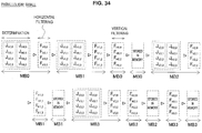
- macro block MBx (MB0, MB1...) each having the size of 16 ⁇ 16 pixels includes the top left vertical boundary represented as Vx,0, the top center vertical boundary represented as Vx,1, the bottom left vertical boundary represented as Vx,2, the bottom center vertical boundary represented as Vx,3, the top left horizontal boundary represented as Hx,0, the top right horizontal boundary represented as Hx,1, the left center horizontal boundary represented as Hx,2, and the right center horizontal boundary represented as Hx,3.
- Concerning boundary Z for example, the filtering need determination process is represented as J Z and the filtering process is represented as F Z .
- Fig. 7 makes it clear that there is no dependency among four filtering processes F V0,0 , F V0,1 , F V0,2 , and F V0,3 (no pixel updated redundantly) within macro block MB0 and the filtering processes can be performed in parallel.
- the above-described existing technique leaves the dependency between the filtering processes on vertical boundaries and the filtering need determination processes on horizontal boundaries.
- the existing technique also leaves the dependency between the filtering processes on horizontal boundaries and the filtering need determination processes on vertical boundaries. If a vertical boundary is processed prior to a horizontal boundary, for example, the filtering need determination processes need to be performed on horizontal boundaries within a given macro block after termination of the filtering processes on vertical boundaries.
- Fig. 8 shows that, within macro block MB0, filtering need determination process J H0,0 depends on results of filtering processes F V0,0 and P V0,1 and filtering need determination process J H0,1 depends on a result of filtering processes F V0,1 .
- filtering need determination processes need to be performed on vertical boundaries within a given macro block after termination of the filtering process on the horizontal boundary for the adjacent macro block.
- Fig. 9 shows that filtering need determination process J V1,0 for macro block MB1 depends on results of filtering processes F H0,1 and F H0,3 for macro block MB0 and filtering need determination process J V1,2 for macro block MB1 depends on a result of filtering process F H0,3 for macro block MB0.
- the existing technique involves the dependency between processes and therefore provides parallel processing of the deblocking filter to a very limited extent even if the technique proposed in JCTVC-A119 is used.
- Fig. 10 is an explanatory diagram illustrating a sequence of deblocking filter processes according to an existing technique.
- the example assumes that the deblocking filter is supplied with an image having the size of 32 ⁇ 32 pixels.
- the input image includes four macro blocks MB0 through MB3 each having the size of 16 ⁇ 16 pixels.
- each broken-line frame represents a process to be performed in parallel.
- the first step performs, in parallel, filtering need determination processes J V0,0 , J V0,1 , J V0,2 and J V0,3 on four vertical boundaries in macro block MB0.
- the second step performs, in parallel, filtering processes F V0,0 , F V0,1 , F V0,2 and F V0,3 on four vertical boundaries in macro block MB0.
- the third step performs, in parallel, filtering need determination processes J H0,0 , J H0,1 , J H0,2 and J H0,3 on four horizontal boundaries in macro block MB0.
- the third step uses a pixel value after the filtering process on the vertical boundary at the second step for the filtering need determination process on the horizontal boundary.
- the fourth step performs, in parallel, filtering processes F H0,0 , F H0,1 , F H0,2 and F H0,3 on four horizontal boundaries in macro block MB0.
- processes (fifth to eighth steps) for macro block MB1 are performed successively.
- the fifth step uses a pixel value after the filtering process on the horizontal boundary of the macro block MB0 at the fourth step for the filtering need determination process on the vertical boundary of the macro block MB1.
- processes (ninth to twelfth steps) for macro block MB2 are performed successively.
- processes (thirteenth to sixteenth steps) for macro block MB3 are performed successively.
- the following describes example configurations of the deblocking filter 24a for the image encoding device 10 shown in Fig. 1 and the deblocking filter 24b for the image decoding device 60 shown in Fig. 2 according to the first working example.
- the configurations of the deblocking filter 24a and the deblocking filter 24b may be common to each other.
- the deblocking filter 24a and the deblocking filter 24b are generically referred to as a deblocking filter 24 when there is no need for distinction between them.
- processes using the deblocking filter 24 also include two types of processes, namely, a filtering need determination process and a filtering process.
- the deblocking filter 24 uses pixel values for an image input to the deblocking filter for the determination across a plurality of macro blocks in the filtering need determination process on one of the vertical boundary and the horizontal boundary. If the vertical boundary is processed prior to the horizontal boundary, for example, the deblocking filter 24 can perform the filtering need determination process on the vertical boundary for a given block without waiting for the filtering process on the horizontal boundary for the neighboring blocks.
- the deblocking filter 24 can perform the filtering need determination process on the horizontal boundary for a given block without waiting for the filtering process on the horizontal boundary for the neighboring blocks. The result is to relieve the dependency of processes between macro blocks.
- Relieving the dependency of processes between macro blocks can parallelize processes between the plurality of macro blocks within an image. For example, this enables to perform filtering need determination processes in parallel on vertical boundaries for all blocks within an input image. This also enables to perform filtering need determination processes in parallel on horizontal boundaries for all blocks within an input image.
- Fig. 11 is an explanatory diagram illustrating a sequence of processes available for the working example.
- the example also assumes that the deblocking filter is supplied with an image having the size of 32 ⁇ 32 pixels.
- the input image includes four macro blocks MB0 through MB3 each having the size of 16 ⁇ 16 pixels.
- each broken-line frame represents a process to be performed in parallel. While the example in Fig. 10 requires 16 process steps for a sequence of processes, the example in Fig. 11 aggregates the same number of processes into four process steps.
- the first step performs, in parallel, filtering need determination processes J V0,0 through J V3,3 and J H0,0 through J H3,3 on all vertical boundaries and all horizontal boundaries of all macro blocks MB0 through MB3.
- the second step performs, in parallel, filtering processes F V0,0 through F V3,3 on 16 vertical boundaries of all macro blocks MB0 through MB3.
- the third step performs, in parallel, filtering need determination processes F H0,0 through F H3,3 on all horizontal boundaries of all macro blocks MB0 through MB3.
- the fourth step performs, in parallel, filtering processes F H0,0 through F H3,3 on 16 horizontal boundaries of all macro blocks MB0 through MB3.
- the third and fourth steps may precede the first and second steps if the horizontal boundary is processed prior to the vertical boundary
- Fig. 11 provides the example of maximizing the parallelism (processes performed in parallel) by parallelizing processes over all macro blocks in an image. While not limited to the example, processes may be parallelized over some macro blocks instead of all macro blocks in an image.
- Fig. 12 is a block diagram illustrating a detailed configuration of the deblocking filter 24 according to the first working example for performing the above-described parallel processes.
- the deblocking filter 24 includes a vertical determination block 110, a horizontal determination block 114, a horizontal filtering block 130, a vertical filtering block 140, and a parallelization control section 150.
- the vertical determination block 110 includes a plurality of vertical boundary determination sections 112-1 through 112-n. Each vertical boundary determination section 112 is supplied with images input to the deblocking filter 24 and determination information used to determine whether filtering is needed.
- the vertical boundary determination sections 112-1 through 112-n determine whether to apply the deblocking filter to vertical boundaries using pixel values for an image input to the deblocking filter 24 across the plurality of macro blocks within the image.
- Each vertical boundary determination section 112 supplies the horizontal filtering block 130 with information indicating a determination result about each vertical boundary such as binary information indicating a determination result that value "1" forces application of the deblocking filter.
- the horizontal filtering block 130 includes a plurality of horizontal filtering sections 132-1 through 132-n. Each horizontal filtering section 132 is supplied with an input image and the determination result about each vertical boundary from the vertical determination block 110.
- a determination result from the corresponding vertical boundary determination section 112 may indicate that the filter needs to be applied.
- each horizontal filtering section 132 applies the deblocking filter for vertical boundary to right and left elements with reference to the vertical boundary.
- Each horizontal filtering section 132 supplies the horizontal determination block 114 and the vertical filtering block 140 with pixel values after filtering for filter-applied pixels and pixel values of the input image for the other pixels.
- the horizontal determination block 114 includes a plurality of horizontal boundary determination sections 116-1 through 116-n. Each horizontal boundary determination section 116 is supplied with pixel values after the filtering performed by the horizontal filtering block 130 and the determination information used to determine whether filtering is needed.
- the horizontal boundary determination section 116-1 through 116-n determine whether to apply the deblocking filter to horizontal boundaries using pixel values after the filtering performed by the horizontal filtering block 130 across the plurality of macro blocks within the image.
- Each horizontal boundary determination section 116 supplies the vertical filtering block 140 with information indicating a determination result about each horizontal boundary.
- the vertical filtering block 140 includes a plurality of vertical filtering sections 142-1 through 142-n. Each vertical filtering section 142 is supplied with pixel values after the filtering performed by the horizontal filtering block 130 and a determination result about each horizontal boundary from the horizontal determination block 114.
- a determination result from the corresponding horizontal boundary determination section 116 may indicate that the filter needs to be applied.
- each vertical filtering section 142 applies the deblocking filter for horizontal boundary to top and bottom elements with reference to the horizontal boundary.
- Each vertical filtering section 142 supplies filter-applied pixels with pixel values after the filtering and the other pixels with pixel values supplied from the horizontal filtering block 130.
- An output from each vertical filtering section 142 may configure an output image from the deblocking filter 24.
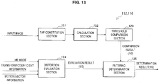
- Fig. 13 is a block diagram illustrating a detailed configuration of each of the vertical boundary determination sections 112 and the horizontal boundary determination sections 116.
- each determination section includes a tap constitution section 121, a calculation section 122, a threshold comparison section 123, a distortion evaluation section 124, and a filtering determination section 125.
- the tap constitution section 121 acquires a reference pixel value from pixel values of two blocks neighboring across a focused boundary in the input image and constitutes a tap (a set of reference pixel values) for determining determination condition B for the above-described luma component.
- a vertical boundary may be focused in the blocks each of which has the size of 8 ⁇ 8 pixels.
- the tap constitution section 121 constitutes a tap from pixel values belonging to the third and sixth rows of two blocks at the right and left. If a horizontal boundary is focused, the tap constitution section 121 constitutes a tap from pixel values belonging to the third and sixth columns of two blocks at the top and bottom.
- the calculation section 122 assigns the tap constituted by the tap constitution section 121 to the left-hand side of the determination expression in determination condition B and calculates an edge value to be compared with edge determination threshold value ⁇ .
- the threshold comparison section 123 compares the value calculated by the calculation section 122 with edge determination threshold value ⁇ and outputs a comparison result to the filtering determination section 125.
- the distortion evaluation section 124 evaluates determination condition A of the above-described luma component using mode information (MB mode), transform coefficient information, and motion vector information supplied as the determination information.
- the distortion evaluation section 124 outputs an evaluation result to the filtering determination section 125.
- the distortion evaluation section 124 evaluates only determination condition A1 of a chroma component based on the mode information.
- the filtering determination section 125 determines whether to apply the deblocking filter to a focused boundary based on a comparison result of determination condition B supplied from the threshold comparison section 123 and an evaluation result of determination condition A supplied from the distortion evaluation section 124.
- the filtering determination section 125 outputs information indicating the determination result.
- the parallelization control section 150 shown in Fig. 12 controls the parallelism of filtering need determination processes in the vertical determination block 110 and the horizontal determination block 114, and the parallelism of filtering processes in the horizontal filtering block 130 and the vertical filtering block 140.
- the parallelization control section 150 may control the parallelism of processes for each block based on an input image size. More specifically, the parallelization control section 150 increases the parallelism of processes for each block if the input image size is relatively large. This can adaptively prevent delay or data rate degradation due to a processing amount that increases according to image sizes.
- the parallelization control section 150 may control the parallelism of processes for each block based on a sequence parameter set, a picture parameter set, or parameters contained in the slice header. This enables to flexibly configure the parallelism according to requirements of users who develop apparatuses. For example the parallelism may be configured according to restrictions on the installation environment such as the number of processor cores or the number of software threads.
- the working example can parallelize processes between macro blocks. This signifies that any sequence of processes on blocks within an image has no effect on a finally output result. Accordingly, the parallelization control section 150 can control a sequence of filtering need determination processes in the vertical determination block 110 and the horizontal determination block 114, and a sequence of filtering processes in the horizontal filtering block 130 and the vertical filtering block 140 on a block basis.
- the parallelization control section 150 may control a sequence of filtering processes according to the dependency of the filtering processes between macro blocks.
- the dependency of processes between neighboring macro blocks around a slice boundary may delay parallel processes on each slice within an image.
- the parallelization control section 150 according to the working example can perform filtering processes on neighboring macro blocks around the slice boundary prior to the other macro blocks.
- Fig. 14 illustrates eight macro blocks MB10 through MB13 and MB20 through MB23 around a slice boundary.
- Macro blocks MB10 through MB13 belong to slice SL1.
- Macro blocks MB20 through MB23 belong to slice SL2.
- Concerning these macro blocks, the filtering processes for horizontal boundaries on macro block MB20 in slice SL2 depend on the filtering processes for vertical boundaries on macro block MB12 in slice SL1.
- the filtering processes for horizontal boundaries on macro block MB21 in slice SL2 depend on the filtering processes for vertical boundaries on macro block MB13 in slice SL1.
- the parallelization control section 150 performs filtering processes on the vertical boundaries of macro blocks MB12 and MB13 out of filtering processes for slice SL1 in preference to processes on the other boundaries. The result is to prevent a large delay from occurring in filtering processes on the horizontal boundaries of macro blocks MB20 and MB21 out of filtering processes for slice SL2.
- An example in Fig. 16 initially performs filtering processes in parallel on vertical boundaries for all macro blocks included in slice SL1. Also in this case, no delay occurs in the filtering process on the horizontal boundaries of macro blocks MB20 and MB21 in slice SL2.
- each vertical boundary determination section 112 references pixels corresponding to the third and sixth rows in a block and determines for vertical boundaries of each block whether filtering is needed similarly to the existing technique as illustrated in Fig. 4 .
- each horizontal boundary determination section 116 references pixels corresponding to the third and sixth columns in a block and determines for horizontal boundaries of each block whether filtering is needed.
- the configuration according to the working example can be easily embodied without changing determination conditions for the filtering need determination process provided for the existing apparatus.
- Each vertical boundary determination section 112 and each horizontal boundary determination section 116 may perform the determination using determination conditions different from the existing technique.
- each vertical boundary determination section 112 may reference pixels corresponding to three or more columns in a block.
- Each horizontal boundary determination section 116 may reference pixels corresponding to three or more columns in a block.
- each vertical boundary determination section 112 and each horizontal boundary determination section 116 may use determination condition expressions different from the existing technique.
- Figs. 17 through 19 the following describes six examples of the determination technique according to the working example.
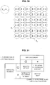
- Fig. 17 is an explanatory diagram illustrating first and second examples of the determination technique.
- the filtering need determination processes (particularly the determination using determination condition B for luma components) for vertical boundaries references pixels of all rows L1 through L8 from the first to the eighth in each block.
- the filtering need determination processes for horizontal boundaries also references pixels of all columns from the first to the eighth in each block.
- the first example may define determination conditions for luma components as follows.
- the deblocking filter is applied if conditions A and B are both true.
- the determination condition for chroma components may be equal to the above-described existing technique.
- a weighted average may be calculated to calculate average iD ave for four determination parameters iD 0 through iD 3 .
- the second example may define determination condition B for luma components as follows.
- An equation to calculate four determination parameters iD 0 through iD 3 is equal to that of the first example.
- An available condition is that not all of, but at least three, two, or one of four determination parameters iD 0 through iD 3 is smaller than edge determination threshold value ⁇ .
- Fig. 18 is an explanatory diagram illustrating third and fourth examples of the determination technique.
- the filtering need determination processes (particularly the determination using determination condition B for luma components) for vertical boundaries references pixels of four rows L1, L3, L6, and L8 in each block.
- the filtering need determination processes for horizontal boundaries also references pixels of four columns in each block.
- the third example may define determination conditions for luma components as follows.
- the deblocking filter is applied if conditions A and B are both true.
- the determination condition for chroma components may be equal to the above-described existing technique.
- a weighted average may be calculated to calculate average iD ave for two determination parameters iD 0 and iD 2 .
- the fourth example may define determination condition B for luma components as follows.
- An equation to calculate two determination parameters iD 0 and iD 2 is equal to that of the third example.
- An available condition is that not both of, but either of two determination parameters iD 0 and iD 2 is smaller than edge determination threshold value ⁇ .
- Fig. 19 is an explanatory diagram illustrating fifth and sixth examples of the determination technique.
- the filtering need determination processes for vertical boundaries references pixels of four rows L1, L3, L5, and L7 in each block.
- the filtering need determination processes for horizontal boundaries also references pixels of four columns in each block.
- the fifth example may define determination conditions for luma components as follows.
- the deblocking filter is applied if conditions A and B are both true.
- the determination condition for chroma components may be equal to the above-described existing technique.
- a weighted average may be calculated to calculate average iD ave for two determination parameters iD 0 and iD 2 .
- the sixth example may define determination condition B for luma components as follows.
- An equation to calculate two determination parameters iD 0 and iD 2 is equal to that of the fifth example.
- An available condition is that not both of, but either of two determination parameters iD 0 and iD 2 is smaller than edge determination threshold value ⁇ .
- the first and second examples of referencing eight rows and columns can minimize a possibility of filtering a block originally not targeted for the deblocking filter to be applied and a possibility of not filtering a block originally targeted for the deblocking filter to be applied.
- the result is to improve the quality of an image to be encoded and decode.
- decreasing the number of rows and columns to be referenced for the determination can reduce processing costs. Since there is trade-off between the image quality and the processing cost, it may be advantageous to adaptively select the number of rows and columns to be referenced for the determination depending on the use of the apparatus or restrictions on the installation. It may be advantageous to adaptively select combinations of rows and columns to be referenced.
- average value iD ave of determination parameters can be compared with edge determination threshold value ⁇ to appropriately perform the determination on a block basis without an excess effect of parameter variations for each row or column.
- Fig. 20 is a flowchart illustrating a process flow for the deblocking filter 24 according to the first working example.
- the vertical boundary determination sections 112-1 through 112-n determine in parallel for all vertical boundaries included in a plurality of macro blocks within an input image whether filtering is needed (step S110).
- the horizontal filtering sections 132-1 through 132-n apply in parallel the deblocking filter to all vertical boundaries determined at step S110 to require the deblocking filter to be applied (step S120).
- the horizontal boundary determination sections 116-1 through 116-n determine in parallel for all horizontal boundaries included in a plurality of macro blocks within an input image whether filtering is needed (step S130).
- the vertical filtering sections 142-1 through 142-n apply in parallel the deblocking filter to all horizontal boundaries determined at step S130 to require the deblocking filter to be applied (step S140).
- the deblocking filter 24 may parallelize processes on two or more macro blocks.
- the sequence of processes may be changed.
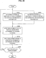
- Fig. 21 is a flowchart illustrating a process flow of the filtering need determination process corresponding to steps S110 and S130 in Fig. 20 .
- the distortion evaluation section 124 evaluates boundaries for distortion based on mode information, transform coefficient information, and motion vector information (step S150).
- the process proceeds to step S154 if the evaluation results in the presence of distortion (determination condition A is true).
- the process proceeds to step S160 if the evaluation results in the absence of distortion (step S152).
- the calculation section 122 calculates an edge value based on a reference pixel tap constituted by the tap constitution section 121 (step S154).
- the threshold comparison section 123 compares the calculated value with edge determination threshold value ⁇ (step S156).
- the process proceeds to step S158 if the edge value is not smaller than threshold value ⁇ (determination condition B is true).
- the process proceeds to step S160 if the edge value is not smaller than threshold value ⁇ .
- the filtering determination section 125 determines to apply the deblocking filter to a boundary to be determined (step S158).
- the filtering determination section 125 determines not to apply the deblocking filter to a boundary to be determined (step S160).
- the deblocking filter 24 performs the filtering need determination process on vertical boundaries of each block without waiting for application of the deblocking filter to the other blocks in the macro block to which the block belongs.
- the deblocking filter 24 performs the filtering need determination process on horizontal boundaries of each block without waiting for application of the deblocking filter to the other blocks in the macro block to which the block belongs. This can relieve the dependency of processes within a macro block.
- Fig. 22 is an explanatory diagram illustrating a first example of process sequence available on the deblocking filter 24.
- the example also assumes that the deblocking filter is supplied with an image having the size of 32 ⁇ 32 pixels.
- the input image includes four macro blocks MB0 through MB3 each having the size of 16 ⁇ 16 pixels.
- each broken-line frame represents a process to be performed in parallel. While the example in Fig. 10 requires 16 process steps for a sequence of processes, the example in Fig. 22 aggregates the same number of processes into 12 process steps.
- the first step performs, in parallel, filtering need determination processes J V0,0 through J V0,3 and J H0,0 through J H0,3 on four vertical boundaries and four horizontal boundaries of macro block MB0.
- the second step performs, in parallel, filtering processes F V0,0 through F V0,3 on four vertical boundaries in macro block MB0.
- the third step performs, in parallel, filtering need determination processes J V1,0 through J V1,3 and J H1,0 through J H1,3 on four vertical boundaries and four horizontal boundaries of macro block MB1.
- the fourth step performs, in parallel, filtering processes F V1,0 through F V1,3 on four vertical boundaries in macro block MB1.
- the fifth step performs, in parallel, filtering processes F H0,0 through F H0,3 on four horizontal boundaries in macro block MB0.
- the sixth step performs, in parallel, filtering need determination processes J V2,0 through J V2,3 and J H2,0 through J H2,3 on four vertical boundaries and four horizontal boundaries of macro block MB2.
- the seventh step performs, in parallel, filtering processes F V2,0 through F V2,3 on four vertical boundaries in macro block MB2.
- the eighth step performs, in parallel, filtering processes F H1,0 through F H1,3 on four horizontal boundaries in macro block MB1.
- the ninth step performs, in parallel, filtering need determination processes J V3,0 through J V3 , 3 and J H3,0 through J H3,3 on four vertical boundaries and four horizontal boundaries of macro block MB3.
- the tenth step performs, in parallel, filtering processes F V3,0 through F V3,3 on four vertical boundaries in macro block MB3.
- the eleventh step performs, in parallel, filtering processes F H2,0 through F H2,3 on four horizontal boundaries in macro block MB2.
- the twelfth step performs, in parallel, filtering processes F H3,0 through F H3,3 on four horizontal boundaries in macro block MB3.
- the deblocking filter 24 can perform a process on the entire input image using process steps fewer than those of the existing technique.
- Fig. 23 is a block diagram illustrating a detailed configuration of the deblocking filter 24 according to the second working example for performing the above-described parallel processes.
- the deblocking filter 24 includes a vertical determination block 210, a horizontal determination block 214, the horizontal filtering block 130, the vertical filtering block 140, and the parallelization control section 150.
- the vertical determination block 210 includes a plurality of vertical boundary determination sections 212-1 through 212-n. Each vertical boundary determination section 212 determines whether to apply the deblocking filter to vertical boundaries of each block without waiting for application of the deblocking filter to the other blocks in the macro block to which the block belongs. Each vertical boundary determination section 212 supplies the horizontal filtering block 130 with information indicating a determination result about each vertical boundary such as binary information indicating a determination result that value "1" forces application of the deblocking filter.
- the horizontal determination block 214 includes a plurality of horizontal boundary determination sections 216-1 through 216-n. Each horizontal boundary determination section 216 determines whether to apply the deblocking filter to horizontal boundaries of each block without waiting for application of the deblocking filter to the other blocks in the macro block to which the block belongs. Each horizontal boundary determination section 216 supplies the vertical filtering block 140 with information indicating a determination result about each horizontal boundary.
- each vertical boundary determination section 212 and each horizontal boundary determination section 216 may determine for each boundary whether filtering is needed by referencing pixels at positions similarly to the existing technique. Instead, each vertical boundary determination section 212 and each horizontal boundary determination section 216 may determine for each boundary whether filtering is needed according to the technique described in "3-2. Determination Condition Modifications.”
- Fig. 24 is a flowchart illustrating a process flow for the deblocking filter 24 according to the second working example.
- the vertical boundary determination sections 212-1 through 212-n determine in parallel for all vertical boundaries included in a focused macro blocks within an input image whether filtering is needed (step S202).
- the horizontal boundary determination sections 214-1 through 214-n determine in parallel whether filtering is needed for all horizontal boundaries included in the focused macro block(step S204). Steps S202 and S204 are also performed in parallel.
- the horizontal filtering sections 132-1 through 132-n apply the deblocking filter in parallel to vertical boundaries in the focused macro block determined at step S202 to require the deblocking filter to be applied (step S210).
- the process at step S220 aims at a focused macro block in the most recent loop.
- the process at step S220 may be skipped for the first focused macro block.
- the vertical filtering sections 142-1 through 142-n apply the deblocking filter in parallel to horizontal boundaries determined, at step S204 in the most recent loop, to require the deblocking filter to be applied (step S220).
- steps S202 through S220 is repeated for a newly focused macro block if focused macro blocks remain unprocessed in the input image (step S230).
- the vertical filtering sections 142-1 through 142-n apply the deblocking filter in parallel to horizontal boundaries determined to require the deblocking filter to be applied in the focused macro block for the last loop (step S240).
- the flow of processes described above is also a mere example.
- the parallelism and sequence of processes may be changed.
- the parallelization control section 150 may control the parallelism and sequence of processes.
- a coding unit having the largest size is referred to as a largest coding unit (LCU) that can be selected as 64 ⁇ 64 pixels, for example.
- the minimum selectable CU size is 8 ⁇ 8 pixels.
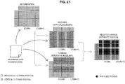
- Fig. 25 is an explanatory diagram illustrating a process sequence for each LCU according to the second working example described above.
- the example assumes the LCU size to be 16 ⁇ 16 pixels and the CU size to be 8 ⁇ 8 pixels.
- the first stage is shown at the top left of the drawing and indicates that the filtering on LCUs has completed up to the (n-1)th LCU. Shaded pixels are targeted for filtering on vertical boundaries. Filled pixels are targeted for filtering on horizontal boundaries.
- the second process at the top right and the third process at the bottom left are targeted for the nth LCU.
- filtering need determination processes are performed in parallel on all vertical boundaries and horizontal boundaries belonging to the nth LCU. Namely, the filtering need determination process on boundaries belonging to CUs in the nth LCU is performed without waiting for application of the deblocking filter to the other CUs in the nth LCU.
- the second process performs filtering processes in parallel on vertical boundaries that belong to the nth LCU and are determined to require the deblocking filter to be applied.
- the second process performs filtering processes in parallel on horizontal boundaries that belong to the nth LCU and are determined to require the deblocking filter to be applied.
- a process for the fourth stage at the bottom right of Fig. 25 is targeted for the (n+1)th LCU.
- the filtering process is performed in parallel on a vertical boundary determined to require the deblocking filter to be applied after the filtering need determination processes are performed in parallel on boundaries belonging to all CUs in the (n+1)th LCU.
- the LCU size may be 16 ⁇ 16 pixels, it may be set to 32 ⁇ 32 or 64 ⁇ 64 pixels.
- the effect of shortening the processing time according to the parallelization is further improved because increasing the size of an LCU to be selected also increases the number of vertical boundaries and horizontal boundaries belonging to one LCU.
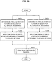
- Fig. 26 is a flowchart illustrating a process flow of the deblocking filter 24 for each LCU.
- the vertical boundary determination sections 212-1 through 212-n determine in parallel whether filtering is needed for all vertical boundaries included in a focused LCU within an input image (step S252).
- the horizontal boundary determination sections 216-1 through 216-n determine in parallel whether filtering is needed for all horizontal boundaries included in the focused LCU (step S254). Steps S252 and S254 are also performed in parallel.
- the horizontal filtering sections 132-1 through 132-n apply the deblocking filter in parallel to vertical boundaries in the focused LCU determined at step S252 to require the deblocking filter to be applied (step S260).
- the vertical filtering sections 142-1 through 142-n apply the deblocking filter in parallel to horizontal boundaries in the focused LCU determined at step S254 to require the deblocking filter to be applied (step S270).
- steps S252 through S270 is repeated for a newly focused LCU if an LCU remains unprocessed in the input image (step S280). The process terminates if there remains no LCU unprocessed.
- the first and second working examples change the existing sequence of processes for the deblocking filter to improve the parallelism of processes.
- the first working example relieves the process dependency by extending the scope of pixel values for an input image supplied to the deblocking filter when the necessity of filtering is determined.
- the third working example to be described enhances this concept.
- the third working example further parallelizes processes by filtering input pixel values supplied to the deblocking filter during a filtering process on vertical boundaries and horizontal boundaries.
- Fig. 27 is an explanatory diagram illustrating an overview of the working example.
- a shape representing input pixels also referred to as reconstruct pixels
- the working example allows pixel values input to the deblocking filter to be referenced from a filtering need determination process for vertical boundaries and horizontal boundaries as well as a filtering process for vertical boundaries and a filtering process for horizontal boundaries. Accordingly, this enables to solve the dependency between the two filtering need determination processes and the dependency between the two filtering processes.
- the filtering processes for vertical boundaries and the filtering processes for horizontal boundaries may update values of duplicate pixels.
- Filled pixels in Fig. 27 illustrate positions of the pixels likely to be duplicated.
- the deblocking filter according to the working example calculates one output pixel value from two filter outputs in terms of pixels that are duplicately updated by two filters operating in parallel.
- Fig. 28 is a block diagram illustrating a detailed configuration of the deblocking filter 24 according to the third working example.
- the deblocking filter 24 includes the line memory 308, the determination block 310, a horizontal filtering block 330, a vertical filtering block 340, the parallelization control section 150, and a calculation section 360.
- the line memory 308 stores pixel values for an input image supplied to the deblocking filter 24. Filtering processes in the horizontal filtering block 330 and the vertical filtering block 340 do not update pixel values stored in the line memory 308. Filtering need determination processes performed by sections described below in the determination block 310 reference pixel values stored in the line memory 308.
- the apparatus includes another memory for purposes different from processes of the deblocking filter 24. This memory may be reused (shared) as the line memory 308.
- the determination block 310 includes vertical boundary determination sections 312-1 through 312-n and horizontal boundary determination sections 314-1 through 314-n.
- the vertical boundary determination sections 312 and the horizontal boundary determination sections 314 are supplied with pixel values stored in the line memory 308 for an image input to the deblocking filter 24 and determination information used to determine the need for filtering.
- the vertical boundary determination sections 312 use pixel values input to the deblocking filter 24 to determine whether to apply the deblocking filter to each vertical boundary.
- the vertical boundary determination sections 312 output, to the horizontal filtering block 330, information indicating a determination result about each vertical boundary.
- the horizontal boundary determination sections 314 also use pixel values input to the deblocking filter 24 to determine whether to apply the deblocking filter to each horizontal boundary.
- the horizontal boundary determination sections 314 perform determination processes in parallel to determination processes performed by the vertical boundary determination sections 312.
- the horizontal boundary determination sections 314 output, to the vertical filtering block 340, information indicating a determination result about each horizontal boundary.
- each vertical boundary determination section 312 and each horizontal boundary determination section 314 may determine for each boundary whether filtering is needed by referencing pixels at positions similarly to the existing technique. Instead, each vertical boundary determination section 312 and each horizontal boundary determination section 314 may determine for each boundary whether filtering is needed according to the technique described in "3-2. Determination Condition Modifications.”
- the horizontal filtering block 330 includes horizontal filtering sections 332-1 through 332-n.
- the horizontal filtering sections 332 are supplied with an input image value from the line memory 208 and a determination result concerning each vertical boundary from the determination block 310.
- the horizontal filtering sections 332 apply the deblocking filter for vertical boundaries to right and left pixels around the corresponding vertical boundary if the determination result from the vertical boundary determination section 312 indicates that the filter needs to be applied.
- the horizontal filtering sections 332 output, to the calculation section 360, a pixel value after the filtering in terms of the filtered pixel or an input pixel value in terms of the other pixels.
- the vertical filtering block 340 includes vertical filtering sections 342-1 through 342-n.
- the vertical filtering sections 342 are supplied with an input pixel value from the line memory 308 and a determination result concerning each horizontal boundary from the determination block 310.
- the vertical filtering sections 342 apply the deblocking filter for horizontal boundaries to top and bottom pixels around the corresponding horizontal boundary if the determination result from the horizontal boundary determination section 314 indicates that the filter needs to be applied. Filtering processes of the vertical filtering sections 342-1 through 342-n are performed in parallel to filtering processes of the horizontal filtering sections 332-1 through 332-n.
- the vertical filtering sections 342 output, to the calculation section 360, a pixel value after the filtering in terms of the filtered pixel or an input pixel value in terms of the other pixels.
- the calculation section 360 is supplied with an output pixel value from the horizontal filtering block 330 and an output pixel value from the vertical filtering block 340 in parallel. Further, the calculation section 360 is supplied with determination results from the vertical boundary determination section 312 and the horizontal boundary determination section 314. According to a determination result, the calculation section 360 calculates output pixel values for pixels filtered from the horizontal filtering block 330 and the vertical filtering block 340 based on filter outputs from the horizontal filtering block 330 and the vertical filtering block 340.
- the calculation section 360 calculates an average of two filter outputs for duplicately filtered pixels.
- the calculation section 360 may calculate a simple average of two filter outputs.
- the calculation section 360 may calculate a weighted average of two filter outputs.
- the calculation section 360 may determine a weight for weighted averages of pixels according to the distance from each pixel to the vertical boundary and to the horizontal boundary.
- Fig. 29 is an explanatory diagram illustrating determination of a weight for weighted average calculated by the calculation section 360.
- Fig. 29 shows focused pixel P Z in black corresponding to one of the duplicated positions illustrated in Fig. 27 .
- Distance D H is smaller than distance D V .
- the calculation section 360 may set a weight for output from the deblocking filter applied to horizontal boundary H Z to be larger than a weight for output from the deblocking filter applied to vertical boundary V Z .
- the example in Fig. 29 assumes that a ratio of filter output V out for vertical boundary V Z to filter output H out for horizontal boundary H Z is 2:3.
- calculating a weighted average of two filter outputs can consequently provide each focused pixel with an output pixel value similar to the case of applying one two-dimensional filter having a filter tap along the horizontal direction and a filter tap along the vertical direction.
- Parallelizing filtering processes on the vertical boundary and the horizontal boundary can also appropriately reduce block distortion appearing on the vertical boundary and the horizontal boundary.
- the deblocking filter 24 may include one two-dimensional filter that simultaneously calculates horizontal filtering, vertical filtering, and a weighted average. In this case, however, the installation is very complicated because filter coefficients need to be variously changed correspondingly to pixels.
- the third working example performs two one-dimensional filters in parallel and then calculates a weighted average. This can easily provide processes substantially equal to a two-dimensional filter while ensuring the functionality of existing deblocking filters.
- Fig. 30 is an explanatory diagram illustrating an example of the weight for weighted averages calculated based on the example in Fig. 29 .
- Fig. 30 shows 36 pixels (6 ⁇ 6) around an intersection between the vertical boundary and the horizontal boundary. The pixels correspond to the above-described duplicated positions.
- the ratio of the weight for filter output V out to the weight for filter output H out is 1:1 (2:2 or 3:3) for pixels positioned at an equal distance from the vertical boundary and the horizontal boundary.
- the weight for filter output V out is larger than the weight for filter output H out for pixels nearer to the vertical boundary.
- the weight for filter output V out is smaller than the weight for filter output H out for pixels nearer to the horizontal boundary.
- the block distortion can be more effectively suppressed and the image quality can be improved by varying the weight for weighted averages depending on the distance between each pixel and the boundary.
- the calculation section 360 may determine the weight of weighted averages for pixels according to the edge strengths of the vertical boundary and the horizontal boundary corresponding to each pixel instead of or in addition to the distance between each pixel and the boundary.
- the edge strength may be represented with a parameter such as an edge value calculated from the calculation section 122 as shown in Fig. 13 , for example.
- the weight for filer output on a boundary having a stronger edge may be set to be larger than the weight for filer output on a boundary having a weaker edge. Varying the weight of weighted averages according to the edge strength can adaptively improve the effect of the deblocking filter at a boundary that remarkably causes block distortion.
- the calculation section 360 selects outputs from actually filtered blocks in terms of pixels filtered by one of the horizontal filtering block 330 and the vertical filtering block 340.
- the calculation section 360 directly outputs an input pixel value to be output to the deblocking filter 24 in terms of pixels not filtered by the horizontal filtering block 330 or the vertical filtering block 340.
- a table in Fig. 31 lists output pixel values from the calculation section 360 according to results of the determination whether to require the filtering.
- the following describes two examples of process sequences available for the deblocking filter 24 according to the working example.
- the example also assumes that the deblocking filter is supplied with an image having the size of 32 ⁇ 32 pixels.
- the input image includes four macro blocks MB0 through MB3 each having the size of 16 ⁇ 16 pixels.
- Fig. 32 illustrates a process sequence when the dependency remains between a filtering process on the vertical boundary and a filtering process on the horizontal boundary.
- the first step performs, in parallel, filtering need determination processes J V0,0 through J V3,3 and J H0,0 through J H3,3 on all vertical boundaries and all horizontal boundaries of all the four macro blocks MB0 through MB3.
- the second step performs filtering processes F V0,0 through F V3,3 on 16 vertical boundaries of the four macro blocks MB0 through MB3.
- the third step performs filtering processes F H0,0 through F H3,3 on 16 horizontal boundaries of the four macro blocks MB0 through MB3.
- the fourth step stores pixel values after the filtering process on the horizontal boundary in the memory used for outputs from the deblocking filter 24.
- Fig. 33 illustrates a first example of process sequence provided by the working example.
- the first step performs, in parallel, filtering need determination processes J V0,0 through J V3,3 and J H0,0 through J H3,3 on all vertical boundaries and all horizontal boundaries of the four macro blocks MB0 through MB3.
- the second step performs, in parallel, filtering processes F V0,0 through F V3,3 and F H0,0 through F H3,3 on all vertical boundaries and all horizontal boundaries of the four macro blocks MB0 through MB3.
- the second step filters only a boundary determined to require the filtering.
- the third step stores pixel values in the memory used for outputs from the deblocking filter 24. A weighted average of two filter outputs may be calculated as an output pixel value in terms of pixels filtered by the horizontal filtering block 330 and the vertical filtering block 340.
- the deblocking filter 24 according to the second example can also perform a process for each macro block.
- Fig. 34 illustrates a process sequence for each macro block when the dependency remains between a filtering process on the vertical boundary and a filtering process on the horizontal boundary.
- the process sequence in Fig. 34 substantially equals the process sequence in Fig. 22 according to the first working example.
- Fig. 36 explicitly shows the four process steps (sixth, tenth, 14th, and 16th) that store pixel values in the memory for output and are omitted from Fig. 22 for simplicity. Sixteen process steps including the four process steps configure the process in Fig. 34 .
- Fig. 35 illustrates a second example of process sequence provided by the working example.
- the first step performs, in parallel, filtering need determination processes J V0,0 through J V0,3 and J H0,0 through J H0,3 on four vertical boundaries and four horizontal boundaries of macro block MB0.
- the second step performs, in parallel, filtering processes F V0,0 through F V0,3 and F H0,0 through F H0,3 on four vertical boundaries and four horizontal boundaries of macro block MB0.
- the third step stores pixel values of macro block MB0 in the memory used for outputs from the deblocking filter 24. A weighted average of two filter outputs may be calculated as an output pixel value in terms of pixels duplicately filtered by two filters.
- the fourth to sixth steps similarly process macro block MB1.
- the seventh to ninth steps similarly process macro block MB2.
- the tenth to twelfth steps similarly process macro block MB3.
- the process in Fig. 35 includes twelve process steps fewer than those of the process in Fig. 34 .
- the third working example eliminates the dependency between filtering processes for vertical boundaries and a filtering process for horizontal boundaries.
- the process of the deblocking filter 24 can be performed using fewer process steps than those used for the first and second working examples.
- One of advantages of allowing a filtering process to reference only pixels input to the deblocking filter is that any configuration of filter taps causes no dependency between filtering processes for vertical boundaries and filtering processes for horizontal boundaries.
- the third working example can improve the image quality by configuring a filter tap using more pixels than used for existing techniques. For example, the existing technique uses a filter tap of three pixels for each side of each boundary as described with reference to Fig. 7 .
- the working example causes no dependency between processes even if a filter tap of five pixels or more is used at each boundary. No dependency occurs between processes even by further decreasing the block size as a process unit for the deblocking filter.
- the parallelization control section 150 may control the parallelism and sequence of processes in the deblocking filter 24.
- Fig. 36 is a flowchart illustrating an example of a process flow for the deblocking filter according to the third working example.
- Fig. 37 is a flowchart illustrating a flow of the pixel value calculation process shown in Fig. 36 .
- the vertical boundary determination sections 312-1 through 312-n determine in parallel whether filtering is needed for all vertical boundaries within an input image or a macro block (step S302).
- the horizontal boundary determination sections 314-1 through 314-n determine in parallel whether filtering is needed for all horizontal boundaries within the input image or the macro block (step S304). Steps S302 and S304 are also performed in parallel.
- the horizontal filtering sections 332-1 through 332-n apply the deblocking filter in parallel to all vertical boundaries determined at step S302 to require the deblocking filter to be applied (step S306).
- the vertical filtering sections 342-1 through 342-n apply the deblocking filter in parallel to all horizontal boundaries determined at step S304 to require the deblocking filter to be applied (step S308). Steps S306 and S308 are also performed in parallel.
- the calculation section 360 then performs the pixel value calculation process as shown in Fig. 37 (step S310). With reference to Fig. 37 , the process from step S314 to step S326 loops for each pixel to be processed (step S312).
- step S314 the calculation section 360 determines whether two filters for vertical boundaries and horizontal boundaries have filtered a focused pixel (step S314). The process proceeds to step S322 if the two filters have filtered the focused pixel. The process proceeds to step S316 if the two filters have not filtered the focused pixel.
- step S316 the calculation section 360 determines whether one of the two filters for vertical boundaries and horizontal boundaries has filtered the focused pixel (step S316). The process proceeds to step S320 if one of the two filters has filtered the focused pixel. The process proceeds to step S318 if none of the filters has filtered the focused pixel.
- the calculation section 360 acquires an input pixel value to the deblocking filter 24 (step S318).
- the calculation section 360 acquires a filter output from the filter that actually filters the focused pixel (step S320).
- the calculation section 360 determines weight values for calculating a weighted average of filter outputs from the two filters concerning the focused pixel according to distances from the focused pixel to the vertical boundary and the horizontal boundary or the edge strengths of the vertical boundary and the horizontal boundary corresponding to the focused pixel (step S322).
- the calculation section 360 calculates a weighted average of filter outputs from the two filters using the determined weight (step S324).
- the calculation section 360 stores the pixel value of the focused pixel in the memory while the pixel value is acquired at step S318 or S320 or is calculated at step S324 (step S326).
- the sequences of processes as shown in Figs. 36 and 37 terminate when the process is performed on all pixels to be processed.
- the technology according to the disclosure is applicable to various codecs related to image encoding and decoding.
- the following describes examples of applying the technology according to the disclosure to multiview codec and scalable codec.
- the multiview codec is an image encoding scheme that encodes and decodes multiple-perspective video.
- Fig. 38 is an explanatory diagram illustrating the multiview codec.
- Fig. 38 illustrates sequences of frames for three views captured at three observing points. Each view is provided with a view ID (view_id). One of the views is specified as a base view. Views other than the base view are referred to as non-base views.
- the example in Fig. 38 represents a base view with view ID "0" and two non-base views with view ID "1" or "2.”
- Encoding multiview image data may compress the data size of the encoded stream as a whole by encoding frames of the non-base view based on encoding information about frames of the base view.
- the deblocking filter may be applied to each view during the encoding process and the decoding process according to the multiview codec described above.
- Application of the deblocking filter to each view may parallelize horizontal filtering and vertical filtering in units of processes including multiple CUs for each view according to the technology of the disclosure.
- the above-described process unit may represent several CUs, LCUs, or pictures.
- the parameter (such as the one described in the preceding paragraph 0092) to control a parallel process may be set for each view.
- the parameter set for the base view may be reused for the non-base view.
- the horizontal filtering and the vertical filtering may be parallelized over a plurality of views.
- the plurality of views may share the parameter (such as the one described in the preceding paragraph 0092) to control the parallel process. It may be advantageous to additionally specify a flag indicating whether the plurality of views share the parameter.
- Fig. 39 is an explanatory diagram illustrating the image encoding process applied to the multiview codec described above.
- Fig. 39 shows a configuration of a multiview encoding device 710 as an example.
- the multiview encoding device 710 includes a first encoding section 720, a second encoding section 730, and a multiplexing section 740.
- the first encoding section 720 encodes a base view image and generates an encoded stream for the base view.
- the second encoding section 730 encodes a non-base view image and generates an encoded stream for the non-base view.
- the multiplexing section 740 multiplexes an encoded stream for the base view generated from the first encoding section 720 and one or more encoded streams for the non-base view generated from the second encoding section 730 to generate a multiplexed stream for multiview.
- the first encoding section 720 and the second encoding section 730 illustrated in Fig. 39 are configured similarly to the image encoding device 10 according to the above-described embodiment. Applying the deblocking filter to views enables to parallelize the horizontal filtering and the vertical filtering in units of processes containing multiple CUs. A parameter to control these processes may be inserted into a header area of the encoded stream for each view or into a common header area in the multiplexed stream.
- Fig. 40 is an explanatory diagram illustrating an image decoding process applied to the multiview codec described above.
- Fig. 40 shows a configuration of a multiview decoding device 760 as an example.
- the multiview decoding device 760 includes a demultiplexing section 770, a first decoding section 780, and a second decoding section 790.
- the demultiplexing section 770 demultiplexes a multiplexed stream for multiview into an encoded stream for the base view and an encoded stream for one or more non-base views.
- the first decoding section 780 decodes a base view image from an encoded stream for the base view.
- the second decoding section 730 decodes a non-base view image from an encoded stream for the non-base view.
- the first decoding section 780 and the second decoding section 790 illustrated in Fig. 40 are configured similarly to the image decoding device 60 according to the above-described embodiment. Applying the deblocking filter to views enables to parallelize horizontal filtering in units of processes including multiple CUs and parallelize vertical filtering. A parameter to control these processes may be acquired from a header area of the encoded stream for each view or from a common header area in the multiplexed stream.
- the scalable codec is an image encoding scheme to provide hierarchical encoding.
- Fig. 41 is an explanatory diagram illustrating the scalable codec.
- Fig. 41 illustrates frame sequences for three layers of different space resolutions, time resolutions, or image qualities. Each layer is provided with a layer ID (layer_id). These layers include a base layer having the lowest resolution (or image quality). Layers other than the base layer are referred to as enhancement layers.
- the example in Fig. 41 represents a base layer with layer ID "0" and two enhancement layers with layer ID "1" or "2.”
- Encoding multi-layer image data may compress the data size of the encoded stream as a whole by encoding frames of the enhancement layer based on encoding information about frames of the base layer.
- the deblocking filter may be applied to each layer during the encoding process and the decoding process according to the scalable codec described above.
- Application of the deblocking filter to each layer may parallelize horizontal filtering and vertical filtering in units of processes including multiple CUs for each view according to the technology of the disclosure.
- the above-described process unit may represent several CUs, LCUs, or pictures.
- the parameter (such as the one described in the preceding paragraph 0092) to control a parallel process may be set for each layer.
- the parameter set for the base layer view may be reused for the enhancement layer.
- the horizontal filtering and the vertical filtering may be parallelized over a plurality of layers.
- the plurality of layers may share the parameter (such as the one described in the preceding paragraph 0092) to control the parallel process. It may be advantageous to additionally specify a flag indicating whether the plurality of layers share the parameter.
- Fig. 42 is an explanatory diagram illustrating the image encoding process applied to the scalable codec described above.
- Fig. 42 shows a configuration of a scalable encoding device 810 as an example.
- the scalable encoding device 810 includes a first encoding section 820, a second encoding section 830, and a multiplexing section 840,
- the first encoding section 820 encodes a base layer image and generates an encoded stream for the base layer.
- the second encoding section 830 encodes an enhancement layer image and generates an encoded stream for the enhancement layer.
- the multiplexing section 840 multiplexes an encoded stream for the base layer generated from the first encoding section 820 and one or more encoded streams for the enhancement layer generated from the second encoding section 830 to generate a multiplexed stream for multi-layer.
- the first encoding section 820 and the second encoding section 830 illustrated in Fig. 42 are configured similarly to the image encoding device 10 according to the above-described embodiment. Applying the deblocking filter to layers enables to parallelize horizontal filtering in units of processes including multiple CUs and parallelize vertical filtering. A parameter to control these processes may be inserted into a header area of the encoded stream for each layer or into a common header area in the multiplexed stream.
- Fig. 43 is an explanatory diagram illustrating an image decoding process applied to the scalable codec described above.
- Fig. 43 shows a configuration of a scalable decoding device 860 as an example.
- the scalable decoding device 860 includes a demultiplexing section 870, a first decoding section 880, and a second decoding section 890.
- the demultiplexing section 870 demultiplexes a multiplexed stream for multi-layer into an encoded stream for the base layer and an encoded stream for one or more enhancement layers.
- the first decoding section 880 decodes a base layer image from an encoded stream for the base layer.
- the second decoding section 830 decodes an enhancement layer image from an encoded stream for the enhancement layer.
- the first decoding section 880 and the second decoding section 890 illustrated in Fig. 43 are configured similarly to the image decoding device 60 according to the above-described embodiment. Applying the deblocking filter to layers enables to parallelize horizontal filtering in units of processes including multiple CUs and parallelize vertical filtering. A parameter to control these processes may be acquired from a header area of the encoded stream for each layer or from a common header area in the multiplexed stream.
- the image encoding device 10 and the image decoding device 60 may be applied to various electronic appliances such as a transmitter and a receiver for satellite broadcasting, cable broadcasting such as cable TV, distribution on the Internet, distribution to terminals via cellular communication, and the like, a recording device that records images in a medium such as an optical disc, a magnetic disk or a flash memory, a reproduction device that reproduces images from such storage medium, and the like.
- various electronic appliances such as a transmitter and a receiver for satellite broadcasting, cable broadcasting such as cable TV, distribution on the Internet, distribution to terminals via cellular communication, and the like
- a recording device that records images in a medium such as an optical disc, a magnetic disk or a flash memory
- reproduction device that reproduces images from such storage medium, and the like.
- FIG. 44 is a block diagram showing an example of a schematic configuration of a television adopting the embodiment described above.
- a television 900 includes an antenna 901, a tuner 902, a demultiplexer 903, a decoder 904, an video signal processing section 905, a display section 906, an audio signal processing section 907, a speaker 908, an external interface 909, a control section 910, a user interface 911, and a bus 912.
- the tuner 902 extracts a signal of a desired channel from broadcast signals received via the antenna 901, and demodulates the extracted signal. Then, the tuner 902 outputs an encoded bit stream obtained by demodulation to the demultiplexer 903. That is, the tuner 902 serves as transmission means of the televisions 900 for receiving an encoded stream in which an image is encoded.
- the demultiplexer 903 separates a video stream and an audio stream of a program to be viewed from the encoded bit stream, and outputs each stream which has been separated to the decoder 904. Also, the demultiplexer 903 extracts auxiliary data such as an EPG (Electronic Program Guide) from the encoded bit stream, and supplies the extracted data to the control section 910. Additionally, the demultiplexer 903 may perform descrambling in the case the encoded bit stream is scrambled.
- EPG Electronic Program Guide
- the decoder 904 decodes the video stream and the audio stream input from the demultiplexer 903. Then, the decoder 904 outputs video data generated by the decoding process to the video signal processing section 905. Also, the decoder 904 outputs the audio data generated by the decoding process to the audio signal processing section 907.
- the video signal processing section 905 reproduces the video data input from the decoder 904, and causes the display section 906 to display the video.
- the video signal processing section 905 may also cause the display section 906 to display an application screen supplied via a network. Further, the video signal processing section 905 may perform an additional process such as noise removal, for example, on the video data according to the setting.
- the video signal processing section 905 may generate an image of a GUI (Graphical User Interface) such as a menu, a button, a cursor or the like, for example, and superimpose the generated image on an output image.
- GUI Graphic User Interface
- the display section 906 is driven by a drive signal supplied by the video signal processing section 905, and displays a video or an image on an video screen of a display device (for example, a liquid crystal display, a plasma display, an OLED, or the like).
- a display device for example, a liquid crystal display, a plasma display, an OLED, or the like.
- the audio signal processing section 907 performs reproduction processes such as D/A conversion and amplification on the audio data input from the decoder 904, and outputs audio from the speaker 908. Also, the audio signal processing section 907 may perform an additional process such as noise removal on the audio data.
- the external interface 909 is an interface for connecting the television 900 and an external appliance or a network.
- a video stream or an audio stream received via the external interface 909 may be decoded by the decoder 904. That is, the external interface 909 also serves as transmission means of the televisions 900 for receiving an encoded stream in which an image is encoded.
- the control section 910 includes a processor such as a CPU (Central Processing Unit), and a memory such as an RAM (Random Access Memory), an ROM (Read Only Memory), or the like.
- the memory stores a program to be executed by the CPU, program data, EPG data, data acquired via a network, and the like.
- the program stored in the memory is read and executed by the CPU at the time of activation of the television 900, for example.
- the CPU controls the operation of the television 900 according to an operation signal input from the user interface 911, for example, by executing the program.
- the user interface 911 is connected to the control section 910.
- the user interface 911 includes a button and a switch used by a user to operate the television 900, and a receiving section for a remote control signal, for example.
- the user interface 911 detects an operation of a user via these structural elements, generates an operation signal, and outputs the generated operation signal to the control section 910.
- the bus 912 interconnects the tuner 902, the demultiplexer 903, the decoder 904, the video signal processing section 905, the audio signal processing section 907, the external interface 909, and the control section 910.
- the decoder 904 has a function of the image decoding device 60 according to the embodiment described above. Accordingly, also in the case of the image decoding in the television 900, it is possible to enhance the parallelism of deblocking filter processes and ensure high-speed processing.
- FIG. 45 is a block diagram showing an example of a schematic configuration of a mobile phone adopting the embodiment described above.
- a mobile phone 920 includes an antenna 921, a communication section 922, an audio codec 923, a speaker 924, a microphone 925, a camera section 926, an image processing section 927, a demultiplexing section 928, a recording/reproduction section 929, a display section 930, a control section 931, an operation section 932, and a bus 933.
- the antenna 921 is connected to the communication section 922.
- the speaker 924 and the microphone 925 are connected to the audio codec 923.
- the operation section 932 is connected to the control section 931.
- the bus 933 interconnects the communication section 922, the audio codec 923, the camera section 926, the image processing section 927, the demultiplexing section 928, the recording/reproduction section 929, the display section 930, and the control section 931.
- the mobile phone 920 performs operation such as transmission/reception of audio signal, transmission/reception of emails or image data, image capturing, recording of data, and the like, in various operation modes including an audio communication mode, a data communication mode, an image capturing mode, and a videophone mode.
- an analogue audio signal generated by the microphone 925 is supplied to the audio codec 923.
- the audio codec 923 converts the analogue audio signal into audio data, and A/D converts and compresses the converted audio data. Then, the audio codec 923 outputs the compressed audio data to the communication section 922.
- the communication section 922 encodes and modulates the audio data, and generates a transmission signal. Then, the communication section 922 transmits the generated transmission signal to a base station (not shown) via the antenna 921. Also, the communication section 922 amplifies a wireless signal received via the antenna 921 and converts the frequency of the wireless signal, and acquires a received signal.
- the communication section 922 demodulates and decodes the received signal and generates audio data, and outputs the generated audio data to the audio codec 923.
- the audio codec 923 extends and D/A converts the audio data, and generates an analogue audio signal. Then, the audio codec 923 supplies the generated audio signal to the speaker 924 and causes the audio to be output.
- the control section 931 generates text data that makes up an email, according to an operation of a user via the operation section 932, for example. Moreover, the control section 931 causes the text to be displayed on the display section 930. Furthermore, the control section 931 generates email data according to a transmission instruction of the user via the operation section 932, and outputs the generated email data to the communication section 922. Then, the communication section 922 encodes and modulates the email data, and generates a transmission signal. Then, the communication section 922 transmits the generated transmission signal to a base station (not shown) via the antenna 921.
- the communication section 922 amplifies a wireless signal received via the antenna 921 and converts the frequency of the wireless signal, and acquires a received signal. Then, the communication section 922 demodulates and decodes the received signal, restores the email data, and outputs the restored email data to the control section 931.
- the control section 931 causes the display section 930 to display the contents of the email, and also, causes the email data to be stored in the storage medium of the recording/reproduction section 929.
- the recording/reproduction section 929 includes an arbitrary readable and writable storage medium.
- the storage medium may be a built-in storage medium such as an RAM, a flash memory or the like, or an externally mounted storage medium such as a hard disk, a magnetic disk, a magneto-optical disk, an optical disc, an USB memory, a memory card, or the like.
- the camera section 926 captures an image of a subject, generates image data, and outputs the generated image data to the image processing section 927, for example.
- the image processing section 927 encodes the image data input from the camera section 926, and causes the encoded stream to be stored in the storage medium of the recording/reproduction section 929.
- the demultiplexing section 928 multiplexes a video stream encoded by the image processing section 927 and an audio stream input from the audio codec 923, and outputs the multiplexed stream to the communication section 922, for example.
- the communication section 922 encodes and modulates the stream, and generates a transmission signal. Then, the communication section 922 transmits the generated transmission signal to a base station (not shown) via the antenna 921. Also, the communication section 922 amplifies a wireless signal received via the antenna 921 and converts the frequency of the wireless signal, and acquires a received signal.
- These transmission signal and received signal may include an encoded bit stream.
- the communication section 922 demodulates and decodes the received signal, restores the stream, and outputs the restored stream to the demultiplexing section 928.
- the demultiplexing section 928 separates a video stream and an audio stream from the input stream, and outputs the video stream to the image processing section 927 and the audio stream to the audio codec 923.
- the image processing section 927 decodes the video stream, and generates video data.
- the video data is supplied to the display section 930, and a series of images is displayed by the display section 930.
- the audio codec 923 extends and D/A converts the audio stream, and generates an analogue audio signal. Then, the audio codec 923 supplies the generated audio signal to the speaker 924 and causes the audio to be output.
- the image processing section 927 has a function of the image encoding device 10 and the image decoding device 60 according to the embodiment described above. Accordingly, also in the case of encoding and decoding an image in the mobile phone 920, it is possible to enhance the parallelism of deblocking filter processes and ensure high-speed processing.
- Fig. 46 is a block diagram showing an example of a schematic configuration of a recording/reproduction device adopting the embodiment described above.
- a recording/reproduction device 940 encodes, and records in a recording medium, audio data and video data of a received broadcast program, for example.
- the recording/reproduction device 940 may also encode, and record in the recording medium, audio data and video data acquired from another device, for example.
- the recording/reproduction device 940 reproduces, using a monitor or a speaker, data recorded in the recording medium, according to an instruction of a user, for example. At this time, the recording/reproduction device 940 decodes the audio data and the video data.
- the recording/reproduction device 940 includes a tuner 941, an external interface 942, an encoder 943, an HDD (Hard Disk Drive) 944, a disc drive 945, a selector 946, a decoder 947, an OSD (On-Screen Display) 948, a control section 949, and a user interface 950.
- the tuner 941 extracts a signal of a desired channel from broadcast signals received via an antenna (not shown), and demodulates the extracted signal. Then, the tuner 941 outputs an encoded bit stream obtained by demodulation to the selector 946. That is, the tuner 941 serves as transmission means of the recording/reproduction device 940.
- the external interface 942 is an interface for connecting the recording/reproduction device 940 and an external appliance or a network.
- the external interface 942 may be an IEEE 1394 interface, a network interface, an USB interface, a flash memory interface, or the like.
- video data and audio data received by the external interface 942 are input to the encoder 943. That is, the external interface 942 serves as transmission means of the recording/reproduction device 940.
- the encoder 943 encodes the video data and the audio data. Then, the encoder 943 outputs the encoded bit stream to the selector 946.
- the HDD 944 records in an internal hard disk an encoded bit stream, which is compressed content data of a video or audio, various programs, and other pieces of data. Also, the HDD 944 reads these pieces of data from the hard disk at the time of reproducing a video or audio.
- the disc drive 945 records or reads data in a recording medium that is mounted.
- a recording medium that is mounted on the disc drive 945 may be a DVD disc (a DVD-Video, a DVD-RAM, a DVD-R, a DVD-RW, a DVD+, a DVD+RW, or the like), a Blu-ray (registered trademark) disc, or the like, for example.
- the selector 946 selects, at the time of recording a video or audio, an encoded bit stream input from the tuner 941 or the encoder 943, and outputs the selected encoded bit stream to the HDD 944 or the disc drive 945. Also, the selector 946 outputs, at the time of reproducing a video or audio, an encoded bit stream input from the HDD 944 or the disc drive 945 to the decoder 947.
- the decoder 947 decodes the encoded bit stream, and generates video data and audio data. Then, the decoder 947 outputs the generated video data to the OSD 948. Also, the decoder 904 outputs the generated audio data to an external speaker.
- the OSD 948 reproduces the video data input from the decoder 947, and displays a video. Also, the OSD 948 may superimpose an image of a GUI, such as a menu, a button, a cursor or the like, for example, on a displayed video.
- a GUI such as a menu, a button, a cursor or the like
- the control section 949 includes a processor such as a CPU, and a memory such as an RAM or an ROM.
- the memory stores a program to be executed by the CPU, program data, and the like.
- a program stored in the memory is read and executed by the CPU at the time of activation of the recording/reproduction device 940, for example.
- the CPU controls the operation of the recording/reproduction device 940 according to an operation signal input from the user interface 950, for example, by executing the program.
- the user interface 950 is connected to the control section 949.
- the user interface 950 includes a button and a switch used by a user to operate the recording/reproduction device 940, and a receiving section for a remote control signal, for example.
- the user interface 950 detects an operation of a user via these structural elements, generates an operation signal, and outputs the generated operation signal to the control section 949.
- the encoder 943 has a function of the image encoding device 10 according to the embodiment described above.
- the decoder 947 has a function of the image decoding device 60 according to the embodiment described above. Accordingly, also in the case of encoding and decoding an image in the recording/reproduction device 940, it is possible to enhance the parallelism of deblocking filter processes and ensure high-speed processing.
- Fig. 47 is a block diagram showing an example of a schematic configuration of an image capturing device adopting the embodiment described above.
- An image capturing device 960 captures an image of a subject, generates an image, encodes the image data, and records the image data in a recording medium.
- the image capturing device 960 includes an optical block 961, an image capturing section 962, a signal processing section 963, an image processing section 964, a display section 965, an external interface 966, a memory 967, a media drive 968, an OSD 969, a control section 970, a user interface 971, and a bus 972.
- the optical block 961 is connected to the image capturing section 962.
- the image capturing section 962 is connected to the signal processing section 963.
- the display section 965 is connected to the image processing section 964.
- the user interface 971 is connected to the control section 970.
- the bus 972 interconnects the image processing section 964, the external interface 966, the memory 967, the media drive 968, the OSD 969, and the control section 970.
- the optical block 961 includes a focus lens, an aperture stop mechanism, and the like.
- the optical block 961 forms an optical image of a subject on an image capturing surface of the image capturing section 962.
- the image capturing section 962 includes an image sensor such as a CCD, a CMOS or the like, and converts by photoelectric conversion the optical image formed on the image capturing surface into an image signal which is an electrical signal. Then, the image capturing section 962 outputs the image signal to the signal processing section 963.
- the signal processing section 963 performs various camera signal processes, such as knee correction, gamma correction, color correction and the like, on the image signal input from the image capturing section 962.
- the signal processing section 963 outputs the image data after the camera signal process to the image processing section 964.
- the image processing section 964 encodes the image data input from the signal processing section 963, and generates encoded data. Then, the image processing section 964 outputs the generated encoded data to the external interface 966 or the media drive 968. Also, the image processing section 964 decodes encoded data input from the external interface 966 or the media drive 968, and generates image data. Then, the image processing section 964 outputs the generated image data to the display section 965. Also, the image processing section 964 may output the image data input from the signal processing section 963 to the display section 965, and cause the image to be displayed. Furthermore, the image processing section 964 may superimpose data for display acquired from the OSD 969 on an image to be output to the display section 965.
- the OSD 969 generates an image of a GUI, such as a menu, a button, a cursor or the like, for example, and outputs the generated image to the image processing section 964.
- a GUI such as a menu, a button, a cursor or the like
- the external interface 966 is configured as an USB input/output terminal, for example.
- the external interface 966 connects the image capturing device 960 and a printer at the time of printing an image, for example.
- a drive is connected to the external interface 966 as necessary.
- a removable medium such as a magnetic disk, an optical disc or the like, for example, is mounted on the drive, and a program read from the removable medium may be installed in the image capturing device 960.
- the external interface 966 may be configured as a network interface to be connected to a network such as a LAN, the Internet or the like. That is, the external interface 966 serves as transmission means of the image capturing device 960.
- a recording medium to be mounted on the media drive 968 may be an arbitrary readable and writable removable medium, such as a magnetic disk, a magneto-optical disk, an optical disc, a semiconductor memory or the like, for example. Also, a recording medium may be fixedly mounted on the media drive 968, configuring a non-transportable storage section such as a built-in hard disk drive or an SSD (Solid State Drive), for example.
- a non-transportable storage section such as a built-in hard disk drive or an SSD (Solid State Drive), for example.
- the control section 970 includes a processor such as a CPU, and a memory such as an RAM or an ROM.
- the memory stores a program to be executed by the CPU, program data, and the like.
- a program stored in the memory is read and executed by the CPU at the time of activation of the image capturing device 960, for example.
- the CPU controls the operation of the image capturing device 960 according to an operation signal input from the user interface 971, for example, by executing the program.
- the user interface 971 is connected to the control section 970.
- the user interface 971 includes a button, a switch and the like used by a user to operate the image capturing device 960, for example.
- the user interface 971 detects an operation of a user via these structural elements, generates an operation signal, and outputs the generated operation signal to the control section 970.
- the image processing section 964 has a function of the image encoding device 10 and the image decoding device 60 according to the embodiment described above. Accordingly, in the case of encoding and decoding an image in the image capturing device 960, it is possible to enhance the parallelism of deblocking filter processes and ensure high-speed processing.
- FIGs. 1 through 47 there have been described three working examples of the deblocking filter for the image encoding device 10 and the image decoding device 60 according to an embodiment.
- the three working examples relieve the dependency of deblocking filter processes inherent to the existing technique. This can improve the parallelism of processes when the deblocking filter is applied. As a result, it is possible to avoid delay or data rate degradation due to a large processing amount of the deblocking filter and ensure high-speed processing.
- the parallelism and sequences of deblocking filter processes can be flexibly set according to various conditions such as image sizes or installation environment.
- pixel values of an input image supplied to the deblocking filter are referred to across a plurality of macro blocks within the image when determining for one of a vertical boundary and a horizontal boundary whether filtering is needed.
- the result is to relieve the dependency of processes between macro blocks or coding units. Therefore, it is possible to parallelize filtering need determination processes across the plurality of macro blocks or all macro blocks within an image if the parallelism is maximized.
- determinations for vertical boundaries and horizontal boundaries of each block whether filtering is needed are made without waiting for applying deblocking filters to the other blocks in the macro block to which the block belongs. This relieves the dependency of processes between a vertical boundary and a horizontal boundary in a macro block or a coding unit. Accordingly, it is possible to parallelize filtering need determination processes on vertical boundaries and horizontal boundaries in a macro block.
- filtering processes for vertical boundaries and horizontal boundaries filter pixels input to the deblocking filter.
- This configuration can parallelize filtering processes for vertical boundaries and horizontal boundaries each other. This can further accelerate processes of the deblocking filter.
- An output pixel value is calculated based on two filter outputs in terms of a pixel updated by two filtering processes performed in parallel. Parallelizing two filtering processes can also appropriately reduce block distortion appearing on the vertical boundary and the horizontal boundary.
- An output pixel value can be calculated as a weighted average of two filter outputs. This can allow the deblocking filter to more effectively eliminate the block distortion and further improve the image quality.
- the specification has mainly described examples where filtering processes for vertical boundaries precedes filtering processes for horizontal boundaries.
- the above-described effects of the technology according to the disclosure are equally available to a case where filtering processes for horizontal boundaries precede filtering processes for vertical boundaries.
- the deblocking filter processing unit or the macro block may be sized otherwise than described in the specification.
- An available technique may omit the filtering need determination processes and parallelize application of the deblocking filter to vertical boundaries and horizontal boundaries.
- a technique of transmitting information used for deblocking filter process parallelization from the encoding side to the decoding side is not limited to the technique of multiplexing the information into the encoded stream header.
- the information may not be multiplexed into an encoded bit stream but may be transmitted or recorded as separate data associated with the encoded bit stream.
- association signifies ensuring possibility of linking an image (or part of an image such as a slice or a block) contained in the bit stream with information corresponding to the image. Namely, the information may be transmitted over a transmission path different from that used for images (or bit streams).
- the information may be recorded on a recording medium (or a different recording area on the same recording medium) different from that used for images (or bit streams).
- the information and the image (or bit stream) may be associated with each other based on any units such as multiple frames, one frame, or part of a frame.
- filtering processes for vertical boundaries as “horizontal filtering” and filtering processes for horizontal boundaries as “vertical filtering.”
- filtering processes for vertical boundaries uses horizontally positioned filter taps.
- Filtering processes for horizontal boundaries uses vertically positioned filter taps. For this reason, the above-described nomenclature is used for the filtering processes.
Applications Claiming Priority (6)
| Application Number | Priority Date | Filing Date | Title |
|---|---|---|---|
| JP2010272907 | 2010-12-07 | ||
| JP2011004392 | 2011-01-12 | ||
| JP2011045651 | 2011-03-02 | ||
| JP2011117558 | 2011-05-26 | ||
| PCT/JP2011/077954 WO2012077608A1 (fr) | 2010-12-07 | 2011-12-02 | Dispositif de traitement d'images et procédé de traitement d'images |
| EP11846900.6A EP2651129B1 (fr) | 2010-12-07 | 2011-12-02 | Dispositif de traitement d'images et procédé de traitement d'images |
Related Parent Applications (2)
| Application Number | Title | Priority Date | Filing Date |
|---|---|---|---|
| EP11846900.6A Division-Into EP2651129B1 (fr) | 2010-12-07 | 2011-12-02 | Dispositif de traitement d'images et procédé de traitement d'images |
| EP11846900.6A Division EP2651129B1 (fr) | 2010-12-07 | 2011-12-02 | Dispositif de traitement d'images et procédé de traitement d'images |
Publications (1)
| Publication Number | Publication Date |
|---|---|
| EP3582497A1 true EP3582497A1 (fr) | 2019-12-18 |
Family
ID=46207096
Family Applications (4)
| Application Number | Title | Priority Date | Filing Date |
|---|---|---|---|
| EP19186704.3A Pending EP3582498A1 (fr) | 2010-12-07 | 2011-12-02 | Dispositif de traitement d'images et procédé de traitement d'images |
| EP19186682.1A Active EP3582496B1 (fr) | 2010-12-07 | 2011-12-02 | Dispositif de traitement d'images et procédé de traitement d'images |
| EP11846900.6A Active EP2651129B1 (fr) | 2010-12-07 | 2011-12-02 | Dispositif de traitement d'images et procédé de traitement d'images |
| EP19186698.7A Pending EP3582497A1 (fr) | 2010-12-07 | 2011-12-02 | Dispositif de traitement d'images et procédé de traitement d'images |
Family Applications Before (3)
| Application Number | Title | Priority Date | Filing Date |
|---|---|---|---|
| EP19186704.3A Pending EP3582498A1 (fr) | 2010-12-07 | 2011-12-02 | Dispositif de traitement d'images et procédé de traitement d'images |
| EP19186682.1A Active EP3582496B1 (fr) | 2010-12-07 | 2011-12-02 | Dispositif de traitement d'images et procédé de traitement d'images |
| EP11846900.6A Active EP2651129B1 (fr) | 2010-12-07 | 2011-12-02 | Dispositif de traitement d'images et procédé de traitement d'images |
Country Status (17)
| Country | Link |
|---|---|
| US (7) | US9912967B2 (fr) |
| EP (4) | EP3582498A1 (fr) |
| JP (4) | JP6011342B2 (fr) |
| KR (6) | KR101868651B1 (fr) |
| CN (6) | CN106791878B (fr) |
| AU (1) | AU2011339461B2 (fr) |
| BR (1) | BR122020013143B1 (fr) |
| CA (1) | CA2815817C (fr) |
| CO (1) | CO6720978A2 (fr) |
| ES (1) | ES2753587T3 (fr) |
| MX (2) | MX2013006130A (fr) |
| MY (1) | MY174587A (fr) |
| PH (2) | PH12018501811A1 (fr) |
| RU (3) | RU2702219C2 (fr) |
| TW (4) | TWI578762B (fr) |
| WO (1) | WO2012077608A1 (fr) |
| ZA (2) | ZA201303963B (fr) |
Families Citing this family (34)
| Publication number | Priority date | Publication date | Assignee | Title |
|---|---|---|---|---|
| US7295609B2 (en) | 2001-11-30 | 2007-11-13 | Sony Corporation | Method and apparatus for coding image information, method and apparatus for decoding image information, method and apparatus for coding and decoding image information, and system of coding and transmitting image information |
| JP5359657B2 (ja) | 2009-07-31 | 2013-12-04 | ソニー株式会社 | 画像符号化装置および方法、記録媒体、並びにプログラム |
| JP5914962B2 (ja) | 2010-04-09 | 2016-05-11 | ソニー株式会社 | 画像処理装置および方法、プログラム、並びに、記録媒体 |
| CN102835104B (zh) * | 2010-04-14 | 2016-04-13 | 西门子企业通讯有限责任两合公司 | 去块滤波方法 |
| TWI600318B (zh) | 2010-05-18 | 2017-09-21 | Sony Corp | Image processing apparatus and image processing method |
| RU2619720C1 (ru) | 2010-06-04 | 2017-05-17 | Сони Корпорейшн | Устройство и способ обработки изображений |
| CN106791878B (zh) * | 2010-12-07 | 2019-05-14 | 索尼公司 | 图像处理设备和图像处理方法 |
| AU2011339460B2 (en) | 2010-12-07 | 2015-10-29 | Sony Corporation | Image processing device and image processing method |
| JP5741076B2 (ja) | 2010-12-09 | 2015-07-01 | ソニー株式会社 | 画像処理装置及び画像処理方法 |
| JP5884313B2 (ja) | 2011-01-18 | 2016-03-15 | ソニー株式会社 | 画像処理装置、画像処理方法、プログラム及び記録媒体 |
| MY169660A (en) | 2011-02-10 | 2019-04-26 | Velos Media Int Ltd | Image processing device and image processing method |
| CN103416060B (zh) | 2011-03-11 | 2016-12-21 | 索尼公司 | 图像处理装置和方法 |
| TWI530161B (zh) | 2011-06-07 | 2016-04-11 | Sony Corp | Image processing apparatus and method |
| JP5907367B2 (ja) | 2011-06-28 | 2016-04-26 | ソニー株式会社 | 画像処理装置および方法、プログラム、並びに記録媒体 |
| HUE056075T2 (hu) | 2011-06-28 | 2022-01-28 | Sony Group Corp | Képfeldolgozó készülék, képfeldolgozó eljárás |
| ES2835801T3 (es) | 2011-09-09 | 2021-06-23 | Sun Patent Trust | Decisiones de filtro de desbloqueo de baja complejidad |
| TWI632808B (zh) * | 2012-04-06 | 2018-08-11 | 新力股份有限公司 | Image processing device and method |
| KR102070484B1 (ko) * | 2013-10-25 | 2020-01-29 | 미디어텍 인크. | 슬라이스 높이로 균등하게 분할할 수 없는 화상 높이 및/또는 화소 그룹 폭으로 균등하게 분할할 수 없는 슬라이스 폭을 갖는 화상을 처리하는 방법 및 장치 |
| US10038919B2 (en) | 2014-05-29 | 2018-07-31 | Apple Inc. | In loop chroma deblocking filter |
| CN105451025B (zh) * | 2014-07-31 | 2019-03-01 | 富士通株式会社 | 图像处理方法以及装置 |
| US11477484B2 (en) | 2015-06-22 | 2022-10-18 | Qualcomm Incorporated | Video intra prediction using hybrid recursive filters |
| WO2018038492A1 (fr) | 2016-08-21 | 2018-03-01 | 엘지전자(주) | Procédé de codage/décodage d'image, et appareil correspondant |
| CN114040199B (zh) * | 2017-04-06 | 2023-12-12 | 松下电器(美国)知识产权公司 | 解码装置及编码装置 |
| CN110290384A (zh) * | 2018-03-19 | 2019-09-27 | 华为技术有限公司 | 图像滤波方法、装置及视频编解码器 |
| JP7155568B2 (ja) | 2018-03-26 | 2022-10-19 | 東洋製罐グループホールディングス株式会社 | 金属加工物 |
| JP7396294B2 (ja) * | 2018-11-02 | 2023-12-12 | ソニーグループ株式会社 | 画像処理装置及び画像処理方法 |
| WO2020175146A1 (fr) * | 2019-02-27 | 2020-09-03 | ソニー株式会社 | Dispositif de traitement d'image et procédé de traitement d'image |
| WO2020180166A1 (fr) * | 2019-03-07 | 2020-09-10 | 디지털인사이트주식회사 | Procédé et appareil de codage/décodage d'image |
| CN109905709B (zh) * | 2019-03-21 | 2021-05-07 | 南京威翔科技有限公司 | 一种基于流水线重组方式的去方块滤波方法 |
| CN110213579A (zh) * | 2019-06-11 | 2019-09-06 | 上海富瀚微电子股份有限公司 | 双核心计算单元实现环路滤波的方法 |
| MX2022000820A (es) * | 2019-07-19 | 2022-04-06 | Lg Electronics Inc | Metodo y dispositivo de codificacion/decodificacion de imagen usando filtracion, y metodo para transmitir flujo de bits. |
| CN111314579B (zh) * | 2020-02-21 | 2021-10-15 | 苏州浪潮智能科技有限公司 | 一种图像垂直滤波处理的方法及芯片 |
| KR20210125657A (ko) | 2020-04-08 | 2021-10-19 | 삼성디스플레이 주식회사 | 표시장치 |
| KR20210130891A (ko) | 2020-04-22 | 2021-11-02 | 삼성디스플레이 주식회사 | 표시 장치 |
Citations (5)
| Publication number | Priority date | Publication date | Assignee | Title |
|---|---|---|---|---|
| JPS63104586A (ja) * | 1986-10-21 | 1988-05-10 | Sony Corp | ブロツク符号化された画像信号の復号装置 |
| US20060147123A1 (en) * | 2004-12-16 | 2006-07-06 | Hiroshi Kajihata | Data processing apparatus, image processing apparatus, and methods and programs thereof |
| US20080043853A1 (en) * | 2006-08-17 | 2008-02-21 | Fujitsu Limited | Deblocking filter, image encoder, and image decoder |
| US20080123750A1 (en) * | 2006-11-29 | 2008-05-29 | Michael Bronstein | Parallel deblocking filter for H.264 video codec |
| WO2008118562A1 (fr) * | 2007-03-27 | 2008-10-02 | Freescale Semiconductor Inc. | Filtrage de déblocage simplifié pour accès mémoire et complexe de calcul réduits |
Family Cites Families (51)
| Publication number | Priority date | Publication date | Assignee | Title |
|---|---|---|---|---|
| JPS63105586A (ja) | 1986-10-23 | 1988-05-10 | Matsushita Electric Ind Co Ltd | テレビジヨン信号処理方法 |
| US6658379B1 (en) * | 1997-02-10 | 2003-12-02 | Sony Corporation | Wavelet processing with leading and trailing edge extrapolation |
| US6125201A (en) | 1997-06-25 | 2000-09-26 | Andrew Michael Zador | Method, apparatus and system for compressing data |
| KR100269125B1 (ko) * | 1997-10-25 | 2000-10-16 | 윤덕용 | 양자화효과감소를위한영상데이터후처리방법및장치 |
| MXPA01001705A (es) | 1998-08-19 | 2004-09-06 | Urecoats Technologies Inc | Composiciones de reticula elastomerica inetrpenetrante de poliuretano bituminoso. |
| JP4254017B2 (ja) * | 2000-03-10 | 2009-04-15 | ソニー株式会社 | 画像符号化装置及び方法 |
| US7295609B2 (en) | 2001-11-30 | 2007-11-13 | Sony Corporation | Method and apparatus for coding image information, method and apparatus for decoding image information, method and apparatus for coding and decoding image information, and system of coding and transmitting image information |
| CN1305646C (zh) * | 2002-02-15 | 2007-03-21 | 索尼公司 | 有腿的移动机器人腿部装置及该机器人的控制方法 |
| JP4114494B2 (ja) | 2002-03-07 | 2008-07-09 | セイコーエプソン株式会社 | 画像処理装置及び画像処理プログラム、並びに画像処理方法 |
| US7620109B2 (en) * | 2002-04-10 | 2009-11-17 | Microsoft Corporation | Sub-pixel interpolation in motion estimation and compensation |
| JP3743384B2 (ja) * | 2002-04-19 | 2006-02-08 | ソニー株式会社 | 画像符号化装置及び方法、並びに画像復号装置及び方法 |
| US8116379B2 (en) * | 2004-10-08 | 2012-02-14 | Stmicroelectronics, Inc. | Method and apparatus for parallel processing of in-loop deblocking filter for H.264 video compression standard |
| KR100843196B1 (ko) | 2004-12-17 | 2008-07-02 | 삼성전자주식회사 | H.264/avc 비디오 디코더의 디블록킹 필터 |
| KR100679035B1 (ko) * | 2005-01-04 | 2007-02-06 | 삼성전자주식회사 | 인트라 bl 모드를 고려한 디블록 필터링 방법, 및 상기방법을 이용하는 다 계층 비디오 인코더/디코더 |
| US7792385B2 (en) | 2005-01-25 | 2010-09-07 | Globalfoundries Inc. | Scratch pad for storing intermediate loop filter data |
| JP2006270851A (ja) | 2005-03-25 | 2006-10-05 | Victor Co Of Japan Ltd | 画像符号化装置及び画像復号装置 |
| TWI264951B (en) * | 2005-05-19 | 2006-10-21 | Cheertek Inc | Deblock filter method for applying on video encoding/decoding and the apparatus thereof |
| JP4825524B2 (ja) * | 2006-01-31 | 2011-11-30 | 株式会社東芝 | 動画像復号装置および動画像復号方法 |
| CN101076124B (zh) * | 2006-05-18 | 2010-09-08 | 北京大学深圳研究生院 | 去块滤波器 |
| US8542744B2 (en) * | 2006-05-19 | 2013-09-24 | Altera Corporation | Methods and apparatus for providing a scalable deblocking filtering assist function within an array processor |
| US9014280B2 (en) * | 2006-10-13 | 2015-04-21 | Qualcomm Incorporated | Video coding with adaptive filtering for motion compensated prediction |
| US8111760B2 (en) * | 2006-11-16 | 2012-02-07 | Texas Instruments Incorporated | Deblocking filters |
| US20080159407A1 (en) * | 2006-12-28 | 2008-07-03 | Yang Nick Y | Mechanism for a parallel processing in-loop deblock filter |
| CN101472177B (zh) * | 2007-12-27 | 2013-03-06 | 宝利微电子系统控股公司 | 一种块效应检测方法 |
| GB0807804D0 (en) * | 2008-04-29 | 2008-06-04 | Imagination Tech Ltd | Interlaced video edge filtering |
| US20090304086A1 (en) | 2008-06-06 | 2009-12-10 | Apple Inc. | Method and system for video coder and decoder joint optimization |
| JP2010014513A (ja) * | 2008-07-03 | 2010-01-21 | Fuji Electric Holdings Co Ltd | はんだフラックス中の金属成分分析方法 |
| WO2010035403A1 (fr) | 2008-09-25 | 2010-04-01 | パナソニック株式会社 | Dispositif de filtre et procédé pour filtre |
| US8861586B2 (en) * | 2008-10-14 | 2014-10-14 | Nvidia Corporation | Adaptive deblocking in a decoding pipeline |
| JP2010136245A (ja) * | 2008-12-08 | 2010-06-17 | Toshiba Corp | 動画像処理装置及び方法 |
| JP2010141513A (ja) * | 2008-12-10 | 2010-06-24 | Toshiba Corp | 演算装置及び動画像符号化装置 |
| US8611435B2 (en) * | 2008-12-22 | 2013-12-17 | Qualcomm, Incorporated | Combined scheme for interpolation filtering, in-loop filtering and post-loop filtering in video coding |
| JP5087016B2 (ja) * | 2009-01-19 | 2012-11-28 | キヤノン株式会社 | 符号化装置及びその制御方法、コンピュータプログラム |
| JP5344238B2 (ja) | 2009-07-31 | 2013-11-20 | ソニー株式会社 | 画像符号化装置および方法、記録媒体、並びにプログラム |
| JP5359657B2 (ja) | 2009-07-31 | 2013-12-04 | ソニー株式会社 | 画像符号化装置および方法、記録媒体、並びにプログラム |
| US20110123121A1 (en) * | 2009-10-13 | 2011-05-26 | Sony Corporation | Method and system for reducing blocking artefacts in compressed images and video signals |
| JP5914962B2 (ja) | 2010-04-09 | 2016-05-11 | ソニー株式会社 | 画像処理装置および方法、プログラム、並びに、記録媒体 |
| CN106162179B (zh) * | 2010-04-13 | 2019-08-13 | 三星电子株式会社 | 执行去块滤波的对视频进行解码的方法 |
| JPWO2011129090A1 (ja) | 2010-04-13 | 2013-07-11 | パナソニック株式会社 | 符号化歪み除去方法、符号化方法、復号化方法、符号化歪み除去装置、符号化装置、および復号化装置 |
| TWI600318B (zh) | 2010-05-18 | 2017-09-21 | Sony Corp | Image processing apparatus and image processing method |
| WO2011152425A1 (fr) * | 2010-06-03 | 2011-12-08 | シャープ株式会社 | Dispositif de filtrage, dispositif de décodage d'image, dispositif de codage d'image et structure de données de paramètre de filtre |
| RU2619720C1 (ru) | 2010-06-04 | 2017-05-17 | Сони Корпорейшн | Устройство и способ обработки изображений |
| CN106791878B (zh) * | 2010-12-07 | 2019-05-14 | 索尼公司 | 图像处理设备和图像处理方法 |
| AU2011339460B2 (en) | 2010-12-07 | 2015-10-29 | Sony Corporation | Image processing device and image processing method |
| JP5741076B2 (ja) | 2010-12-09 | 2015-07-01 | ソニー株式会社 | 画像処理装置及び画像処理方法 |
| US9414066B2 (en) * | 2011-01-14 | 2016-08-09 | Telefonaktiebolaget Lm Ericsson (Publ) | Deblocking filtering |
| MY169660A (en) | 2011-02-10 | 2019-04-26 | Velos Media Int Ltd | Image processing device and image processing method |
| CN103416060B (zh) | 2011-03-11 | 2016-12-21 | 索尼公司 | 图像处理装置和方法 |
| TWI530161B (zh) | 2011-06-07 | 2016-04-11 | Sony Corp | Image processing apparatus and method |
| JP5907367B2 (ja) | 2011-06-28 | 2016-04-26 | ソニー株式会社 | 画像処理装置および方法、プログラム、並びに記録媒体 |
| CN104396256B (zh) | 2012-06-29 | 2018-11-06 | 威勒斯媒体国际有限公司 | 解码设备和解码方法 |
-
2011
- 2011-12-02 CN CN201710072287.2A patent/CN106791878B/zh active Active
- 2011-12-02 ES ES11846900T patent/ES2753587T3/es active Active
- 2011-12-02 EP EP19186704.3A patent/EP3582498A1/fr active Pending
- 2011-12-02 CN CN201710072281.5A patent/CN106658026B/zh active Active
- 2011-12-02 KR KR1020137013868A patent/KR101868651B1/ko active IP Right Grant
- 2011-12-02 WO PCT/JP2011/077954 patent/WO2012077608A1/fr active Application Filing
- 2011-12-02 BR BR122020013143-8A patent/BR122020013143B1/pt not_active IP Right Cessation
- 2011-12-02 US US13/991,007 patent/US9912967B2/en active Active
- 2011-12-02 AU AU2011339461A patent/AU2011339461B2/en active Active
- 2011-12-02 RU RU2016105596A patent/RU2702219C2/ru active
- 2011-12-02 CN CN201180057796.9A patent/CN103229505B/zh active Active
- 2011-12-02 JP JP2012547834A patent/JP6011342B2/ja active Active
- 2011-12-02 KR KR1020207013244A patent/KR102216571B1/ko active IP Right Grant
- 2011-12-02 CN CN201710072285.3A patent/CN106791877B/zh active Active
- 2011-12-02 RU RU2013125500/07A patent/RU2578665C2/ru active
- 2011-12-02 CN CN201310654537.5A patent/CN103716632B/zh active Active
- 2011-12-02 MY MYPI2013002075A patent/MY174587A/en unknown
- 2011-12-02 EP EP19186682.1A patent/EP3582496B1/fr active Active
- 2011-12-02 EP EP11846900.6A patent/EP2651129B1/fr active Active
- 2011-12-02 KR KR1020197022352A patent/KR102117800B1/ko active IP Right Grant
- 2011-12-02 CA CA2815817A patent/CA2815817C/fr active Active
- 2011-12-02 EP EP19186698.7A patent/EP3582497A1/fr active Pending
- 2011-12-02 CN CN201710072283.4A patent/CN106713934B/zh active Active
- 2011-12-02 PH PH12018501811A patent/PH12018501811A1/en unknown
- 2011-12-02 MX MX2013006130A patent/MX2013006130A/es active IP Right Grant
- 2011-12-02 KR KR1020187016184A patent/KR101962591B1/ko active IP Right Grant
- 2011-12-02 KR KR1020197007962A patent/KR102007626B1/ko active IP Right Grant
- 2011-12-02 KR KR1020187016187A patent/KR101958611B1/ko active IP Right Grant
- 2011-12-05 TW TW104111489A patent/TWI578762B/zh active
- 2011-12-05 TW TW104111488A patent/TWI578761B/zh active
- 2011-12-05 TW TW100144704A patent/TWI514892B/zh active
- 2011-12-05 TW TW104111487A patent/TWI565300B/zh active
-
2013
- 2013-05-29 CO CO13131784A patent/CO6720978A2/es active IP Right Grant
- 2013-05-30 ZA ZA2013/03963A patent/ZA201303963B/en unknown
- 2013-05-31 MX MX2014012150A patent/MX336566B/es unknown
- 2013-07-19 US US13/946,707 patent/US9088786B2/en active Active
-
2015
- 2015-06-17 PH PH12015501384A patent/PH12015501384B1/en unknown
-
2016
- 2016-07-21 JP JP2016142995A patent/JP6213626B2/ja active Active
- 2016-12-30 US US15/395,471 patent/US10003827B2/en active Active
- 2016-12-30 US US15/395,445 patent/US9998766B2/en active Active
-
2017
- 2017-05-02 ZA ZA2017/03025A patent/ZA201703025B/en unknown
- 2017-09-11 JP JP2017173731A patent/JP6471786B2/ja active Active
-
2018
- 2018-04-04 US US15/929,006 patent/US10334279B2/en active Active
-
2019
- 2019-01-15 JP JP2019004264A patent/JP6819702B2/ja active Active
- 2019-05-06 US US16/403,620 patent/US10785504B2/en active Active
- 2019-08-13 RU RU2019125559A patent/RU2019125559A/ru unknown
-
2020
- 2020-08-13 US US16/992,138 patent/US11381846B2/en active Active
Patent Citations (5)
| Publication number | Priority date | Publication date | Assignee | Title |
|---|---|---|---|---|
| JPS63104586A (ja) * | 1986-10-21 | 1988-05-10 | Sony Corp | ブロツク符号化された画像信号の復号装置 |
| US20060147123A1 (en) * | 2004-12-16 | 2006-07-06 | Hiroshi Kajihata | Data processing apparatus, image processing apparatus, and methods and programs thereof |
| US20080043853A1 (en) * | 2006-08-17 | 2008-02-21 | Fujitsu Limited | Deblocking filter, image encoder, and image decoder |
| US20080123750A1 (en) * | 2006-11-29 | 2008-05-29 | Michael Bronstein | Parallel deblocking filter for H.264 video codec |
| WO2008118562A1 (fr) * | 2007-03-27 | 2008-10-02 | Freescale Semiconductor Inc. | Filtrage de déblocage simplifié pour accès mémoire et complexe de calcul réduits |
Non-Patent Citations (2)
| Title |
|---|
| K.UGUR (NOKIAK.R.ANDERSSON (LM ERICSSONA.FULDSETH (TANDBERG TELECOM: "JCTVC-A119:Video coding technology proposal by Tandberg, Nokia, and Ericsson", DOCUMENTS OF THE FIRST MEETING OF THE JOINT COLLABORATIVE TEAM ON VIDEO CODING (JCT-VC, 15 April 2010 (2010-04-15) |
| MASARU IKEDA ET AL: "Parallel deblocking filter", 4. JCT-VC MEETING; 95. MPEG MEETING; 20-1-2011 - 28-1-2011; DAEGU;(JOINT COLLABORATIVE TEAM ON VIDEO CODING OF ISO/IEC JTC1/SC29/WG11AND ITU-T SG.16 ); URL: HTTP://WFTP3.ITU.INT/AV-ARCH/JCTVC-SITE/,, no. JCTVC-D263, 15 January 2011 (2011-01-15), XP030008303, ISSN: 0000-0013 * |
Also Published As
Similar Documents
| Publication | Publication Date | Title |
|---|---|---|
| US11381846B2 (en) | Image processing device and image processing method | |
| US10931955B2 (en) | Image processing device and image processing method that horizontal filtering on pixel blocks | |
| AU2017202277B2 (en) | Image processing device and image processing method |
Legal Events
| Date | Code | Title | Description |
|---|---|---|---|
| PUAI | Public reference made under article 153(3) epc to a published international application that has entered the european phase |
Free format text: ORIGINAL CODE: 0009012 |
|
| STAA | Information on the status of an ep patent application or granted ep patent |
Free format text: STATUS: REQUEST FOR EXAMINATION WAS MADE |
|
| 17P | Request for examination filed |
Effective date: 20190802 |
|
| AC | Divisional application: reference to earlier application |
Ref document number: 2651129 Country of ref document: EP Kind code of ref document: P |
|
| AK | Designated contracting states |
Kind code of ref document: A1 Designated state(s): AL AT BE BG CH CY CZ DE DK EE ES FI FR GB GR HR HU IE IS IT LI LT LU LV MC MK MT NL NO PL PT RO RS SE SI SK SM TR |
|
| STAA | Information on the status of an ep patent application or granted ep patent |
Free format text: STATUS: EXAMINATION IS IN PROGRESS |
|
| 17Q | First examination report despatched |
Effective date: 20201008 |
|
| RAP3 | Party data changed (applicant data changed or rights of an application transferred) |
Owner name: SONY GROUP CORPORATION |
|
| RIC1 | Information provided on ipc code assigned before grant |
Ipc: G06T 7/00 20170101ALN20240131BHEP Ipc: H04N 19/36 20140101ALI20240131BHEP Ipc: H04N 19/86 20140101ALI20240131BHEP Ipc: H04N 19/436 20140101ALI20240131BHEP Ipc: H04N 19/80 20140101ALI20240131BHEP Ipc: H04N 19/182 20140101ALI20240131BHEP Ipc: H04N 19/117 20140101ALI20240131BHEP Ipc: H04N 19/61 20140101ALI20240131BHEP Ipc: H04N 19/176 20140101ALI20240131BHEP Ipc: H04N 19/597 20140101ALI20240131BHEP Ipc: G06T 5/00 20060101ALI20240131BHEP Ipc: H04N 17/00 20060101AFI20240131BHEP |
|
| GRAP | Despatch of communication of intention to grant a patent |
Free format text: ORIGINAL CODE: EPIDOSNIGR1 |
|
| STAA | Information on the status of an ep patent application or granted ep patent |
Free format text: STATUS: GRANT OF PATENT IS INTENDED |
|
| RIC1 | Information provided on ipc code assigned before grant |
Ipc: G06T 7/00 20170101ALN20240221BHEP Ipc: H04N 19/36 20140101ALI20240221BHEP Ipc: H04N 19/86 20140101ALI20240221BHEP Ipc: H04N 19/436 20140101ALI20240221BHEP Ipc: H04N 19/80 20140101ALI20240221BHEP Ipc: H04N 19/182 20140101ALI20240221BHEP Ipc: H04N 19/117 20140101ALI20240221BHEP Ipc: H04N 19/61 20140101ALI20240221BHEP Ipc: H04N 19/176 20140101ALI20240221BHEP Ipc: H04N 19/597 20140101ALI20240221BHEP Ipc: G06T 5/00 20060101ALI20240221BHEP Ipc: H04N 17/00 20060101AFI20240221BHEP |