EP3582286B1 - Battery cell frame and battery module comprising same - Google Patents
Battery cell frame and battery module comprising same Download PDFInfo
- Publication number
- EP3582286B1 EP3582286B1 EP18845031.6A EP18845031A EP3582286B1 EP 3582286 B1 EP3582286 B1 EP 3582286B1 EP 18845031 A EP18845031 A EP 18845031A EP 3582286 B1 EP3582286 B1 EP 3582286B1
- Authority
- EP
- European Patent Office
- Prior art keywords
- battery cell
- coupled
- bus bar
- battery
- variable length
- Prior art date
- Legal status (The legal status is an assumption and is not a legal conclusion. Google has not performed a legal analysis and makes no representation as to the accuracy of the status listed.)
- Active
Links
Images


Classifications
-
- H—ELECTRICITY
- H01—ELECTRIC ELEMENTS
- H01M—PROCESSES OR MEANS, e.g. BATTERIES, FOR THE DIRECT CONVERSION OF CHEMICAL ENERGY INTO ELECTRICAL ENERGY
- H01M10/00—Secondary cells; Manufacture thereof
- H01M10/60—Heating or cooling; Temperature control
- H01M10/65—Means for temperature control structurally associated with the cells
- H01M10/655—Solid structures for heat exchange or heat conduction
-
- H—ELECTRICITY
- H01—ELECTRIC ELEMENTS
- H01M—PROCESSES OR MEANS, e.g. BATTERIES, FOR THE DIRECT CONVERSION OF CHEMICAL ENERGY INTO ELECTRICAL ENERGY
- H01M50/00—Constructional details or processes of manufacture of the non-active parts of electrochemical cells other than fuel cells, e.g. hybrid cells
- H01M50/20—Mountings; Secondary casings or frames; Racks, modules or packs; Suspension devices; Shock absorbers; Transport or carrying devices; Holders
-
- H—ELECTRICITY
- H01—ELECTRIC ELEMENTS
- H01M—PROCESSES OR MEANS, e.g. BATTERIES, FOR THE DIRECT CONVERSION OF CHEMICAL ENERGY INTO ELECTRICAL ENERGY
- H01M10/00—Secondary cells; Manufacture thereof
- H01M10/05—Accumulators with non-aqueous electrolyte
- H01M10/052—Li-accumulators
- H01M10/0525—Rocking-chair batteries, i.e. batteries with lithium insertion or intercalation in both electrodes; Lithium-ion batteries
-
- H—ELECTRICITY
- H01—ELECTRIC ELEMENTS
- H01M—PROCESSES OR MEANS, e.g. BATTERIES, FOR THE DIRECT CONVERSION OF CHEMICAL ENERGY INTO ELECTRICAL ENERGY
- H01M10/00—Secondary cells; Manufacture thereof
- H01M10/04—Construction or manufacture in general
- H01M10/0436—Small-sized flat cells or batteries for portable equipment
-
- H—ELECTRICITY
- H01—ELECTRIC ELEMENTS
- H01M—PROCESSES OR MEANS, e.g. BATTERIES, FOR THE DIRECT CONVERSION OF CHEMICAL ENERGY INTO ELECTRICAL ENERGY
- H01M10/00—Secondary cells; Manufacture thereof
- H01M10/05—Accumulators with non-aqueous electrolyte
- H01M10/058—Construction or manufacture
-
- H—ELECTRICITY
- H01—ELECTRIC ELEMENTS
- H01M—PROCESSES OR MEANS, e.g. BATTERIES, FOR THE DIRECT CONVERSION OF CHEMICAL ENERGY INTO ELECTRICAL ENERGY
- H01M50/00—Constructional details or processes of manufacture of the non-active parts of electrochemical cells other than fuel cells, e.g. hybrid cells
- H01M50/10—Primary casings; Jackets or wrappings
- H01M50/102—Primary casings; Jackets or wrappings characterised by their shape or physical structure
- H01M50/103—Primary casings; Jackets or wrappings characterised by their shape or physical structure prismatic or rectangular
-
- H—ELECTRICITY
- H01—ELECTRIC ELEMENTS
- H01M—PROCESSES OR MEANS, e.g. BATTERIES, FOR THE DIRECT CONVERSION OF CHEMICAL ENERGY INTO ELECTRICAL ENERGY
- H01M50/00—Constructional details or processes of manufacture of the non-active parts of electrochemical cells other than fuel cells, e.g. hybrid cells
- H01M50/20—Mountings; Secondary casings or frames; Racks, modules or packs; Suspension devices; Shock absorbers; Transport or carrying devices; Holders
- H01M50/202—Casings or frames around the primary casing of a single cell or a single battery
-
- H—ELECTRICITY
- H01—ELECTRIC ELEMENTS
- H01M—PROCESSES OR MEANS, e.g. BATTERIES, FOR THE DIRECT CONVERSION OF CHEMICAL ENERGY INTO ELECTRICAL ENERGY
- H01M50/00—Constructional details or processes of manufacture of the non-active parts of electrochemical cells other than fuel cells, e.g. hybrid cells
- H01M50/20—Mountings; Secondary casings or frames; Racks, modules or packs; Suspension devices; Shock absorbers; Transport or carrying devices; Holders
- H01M50/204—Racks, modules or packs for multiple batteries or multiple cells
- H01M50/207—Racks, modules or packs for multiple batteries or multiple cells characterised by their shape
- H01M50/209—Racks, modules or packs for multiple batteries or multiple cells characterised by their shape adapted for prismatic or rectangular cells
-
- H—ELECTRICITY
- H01—ELECTRIC ELEMENTS
- H01M—PROCESSES OR MEANS, e.g. BATTERIES, FOR THE DIRECT CONVERSION OF CHEMICAL ENERGY INTO ELECTRICAL ENERGY
- H01M50/00—Constructional details or processes of manufacture of the non-active parts of electrochemical cells other than fuel cells, e.g. hybrid cells
- H01M50/20—Mountings; Secondary casings or frames; Racks, modules or packs; Suspension devices; Shock absorbers; Transport or carrying devices; Holders
- H01M50/267—Mountings; Secondary casings or frames; Racks, modules or packs; Suspension devices; Shock absorbers; Transport or carrying devices; Holders having means for adapting to batteries or cells of different types or different sizes
-
- H—ELECTRICITY
- H01—ELECTRIC ELEMENTS
- H01M—PROCESSES OR MEANS, e.g. BATTERIES, FOR THE DIRECT CONVERSION OF CHEMICAL ENERGY INTO ELECTRICAL ENERGY
- H01M50/00—Constructional details or processes of manufacture of the non-active parts of electrochemical cells other than fuel cells, e.g. hybrid cells
- H01M50/50—Current conducting connections for cells or batteries
- H01M50/502—Interconnectors for connecting terminals of adjacent batteries; Interconnectors for connecting cells outside a battery casing
- H01M50/503—Interconnectors for connecting terminals of adjacent batteries; Interconnectors for connecting cells outside a battery casing characterised by the shape of the interconnectors
-
- H—ELECTRICITY
- H01—ELECTRIC ELEMENTS
- H01M—PROCESSES OR MEANS, e.g. BATTERIES, FOR THE DIRECT CONVERSION OF CHEMICAL ENERGY INTO ELECTRICAL ENERGY
- H01M2220/00—Batteries for particular applications
- H01M2220/20—Batteries in motive systems, e.g. vehicle, ship, plane
-
- Y—GENERAL TAGGING OF NEW TECHNOLOGICAL DEVELOPMENTS; GENERAL TAGGING OF CROSS-SECTIONAL TECHNOLOGIES SPANNING OVER SEVERAL SECTIONS OF THE IPC; TECHNICAL SUBJECTS COVERED BY FORMER USPC CROSS-REFERENCE ART COLLECTIONS [XRACs] AND DIGESTS
- Y02—TECHNOLOGIES OR APPLICATIONS FOR MITIGATION OR ADAPTATION AGAINST CLIMATE CHANGE
- Y02E—REDUCTION OF GREENHOUSE GAS [GHG] EMISSIONS, RELATED TO ENERGY GENERATION, TRANSMISSION OR DISTRIBUTION
- Y02E60/00—Enabling technologies; Technologies with a potential or indirect contribution to GHG emissions mitigation
- Y02E60/10—Energy storage using batteries
-
- Y—GENERAL TAGGING OF NEW TECHNOLOGICAL DEVELOPMENTS; GENERAL TAGGING OF CROSS-SECTIONAL TECHNOLOGIES SPANNING OVER SEVERAL SECTIONS OF THE IPC; TECHNICAL SUBJECTS COVERED BY FORMER USPC CROSS-REFERENCE ART COLLECTIONS [XRACs] AND DIGESTS
- Y02—TECHNOLOGIES OR APPLICATIONS FOR MITIGATION OR ADAPTATION AGAINST CLIMATE CHANGE
- Y02P—CLIMATE CHANGE MITIGATION TECHNOLOGIES IN THE PRODUCTION OR PROCESSING OF GOODS
- Y02P70/00—Climate change mitigation technologies in the production process for final industrial or consumer products
- Y02P70/50—Manufacturing or production processes characterised by the final manufactured product
Definitions
- the present disclosure relates to a battery cell frame and a battery module including the same, and more particularly, to a battery cell frame that can be modularized and used for common purpose and a battery module including the same.
- a lithium secondary battery usually uses a lithium-based oxide and a carbon material for a positive electrode active material and a negative electrode active material respectively.
- the lithium secondary battery includes an electrode assembly including a positive electrode plate and a negative electrode plate respectively coated with the positive electrode active material and the negative electrode active material with a separator interposed between, and a packaging or a battery case to hermetically receive the electrode assembly therein together with an electrolyte solution.
- the lithium secondary battery includes the positive electrode, the negative electrode with the separator interposed between and the electrolyte, and is classified into a lithium ion battery (LIB) and a polymer lithium ion battery (PLIB) according to the positive and negative electrode active materials used.
- LIB lithium ion battery
- PLIB polymer lithium ion battery
- the electrode of the lithium secondary batteries is formed by applying the positive or negative electrode active material to a current collector of an aluminum or copper sheet, a mesh, a film and a foil and drying it.
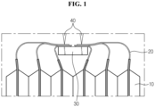
- FIG. 1 is a diagram showing that electrode leads provided in a conventional battery cell and a bus bar are electrically coupled.
- electrode leads 2 provided in each of a plurality of battery cells 1 are bent and brought into contact with a bus bar 3 surface and coupled through welding 4, and in this case, many operators' handwork operations are required to keep the electrode leads 2 in bent shape, the electrode leads 2 and the bus bar 3 do not come into close contact with each other due to the elastic resilience of the metal electrode leads 2, and after the plurality of electrode leads 2 overlap at a point of the bus bar 3, they are welded 4, resulting in reduced weldability.
- US 2011/104556A1 describes a bus bar holder for connecting electrode terminals of a plurality of batteries arranged in a lengthwise direction, the bus bar holder including a bus bar holder plate having an opening in a lengthwise direction thereof and configured such that at least some electrode terminals of the plurality of batteries are extendable through the opening and slidable along the opening; and a bus bar for electrically connecting at least two electrode terminals of adjacent batteries, wherein the bus bar holder plate includes a settling groove in which the bus bar is settled, and the bus bar attached to the electrode terminals is slidable when the electrode terminal slides along the opening.
- the false battery comprises a bracket, a plurality of corner frames, a movable contact point, a contact point bracket and a fixing mechanism, wherein the bracket comprises a plurality of bracket borders; grooves are formed in the corner frames; two ends of various bracket borders are movably arranged in the grooves of the adjacent two bracket borders to form a false battery frame; the movable contact is arranged on the contact point bracket; the contact point bracket is arranged at one side of the false battery frame, and is fastened or adjusted through the fixing mechanism.
- the present disclosure is directed to providing a battery cell frame that allows battery cells in various sizes to be each coupled to one frame and a battery module including the same.
- the present disclosure is further directed to providing a battery cell frame in which a thermal interface material with which a battery cell comes into contact is coupled at a reduced error ratio and a battery module including the same.
- the present disclosure is further directed to providing a battery module having improved weldability with no overlap in electrode leads and a battery pack including the same.
- a battery cell frame including a battery cell, a bus bar which is electrically coupled to an electrode lead of the battery cell, a support member which is coupled to the bus bar and with which the battery cell comes into contact to support the battery cell, and a variable length part formed in the support member and which changes in length to fit a size of the battery cell. Additionally, the variable length part includes a first variable length part which changes in length in a short side direction of the support member, and a second variable length part which changes in length in a long side direction of the support member.
- the first variable length part includes a fixed part which is fixedly coupled to one side of the bus bar, and a moveable part which is moveably coupled to the other side of the bus bar at a location facing the fixed part.
- the bus bar includes an electrical connection part to which the electrode lead of the battery cell is coupled, a first coupling part which extends to one side of the electrical connection part, and to which the fixed part is coupled, and a second coupling part which extends to the other side of the electrical connection part, and to which the moveable part is coupled.
- the bus bar may be coupled to the fixed part and the moveable part at a location that is deviated from a center of the fixed part and a center of the moveable part on the basis of height of the fixed part and the moveable part.
- bus bar may be coupled to the fixed part and the moveable part below the center of the fixed part and the center of the moveable part.
- the second variable length part may have a spiral spring that can shrink and expand by storing energy from rotation or twist.
- a thermal interface material may be coupled to the second variable length part to transfer heat.
- thermal interface material may be coupled to the spiral spring which is in expanded state.
- thermal interface material may be coupled around at least a portion of the spiral spring.
- a battery module including the above-described battery cell frame, wherein a plurality of battery cells is provided and stacked one another.
- an electrode lead of the battery cell may be stepped and coupled to the bus bar.
- a battery pack including the above-described battery module as defined in claim 10 and a vehicle including the above-described battery module as defined in claim 11.
- a frame has a variable length part that changes in length to fit the size of a battery cell, and thus there is an effect that battery cells in various sizes can be each coupled to one frame.
- a thermal interface material is coupled to the second variable length part and comes into contact with the battery cell, and thus there is an effect on the reduced error ratio.
- a plurality of electrode leads is each coupled to a plurality of bus bars to avoid overlap of the electrode leads, and thus there is an effect on the improved weldability.
- Couple or “connect” refers to an element being directly coupled or connected to another element as well as indirectly coupled or connected through intervening elements.
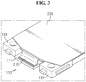
- FIG. 2 is a full perspective view schematically showing a battery cell coupled to a battery cell frame according to an embodiment of the present disclosure
- FIG. 3 is a perspective view showing an electrode lead coupled to a bus bar in the battery cell frame according to an embodiment of the present disclosure
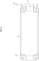
- FIG. 4 is a plane view of the battery cell frame according to an embodiment of the present disclosure
- FIGS. 5(a) and 5(b) are diagrams showing a length change by a first variable length part in the battery cell frame of FIG. 4
- FIG. 6 is a diagram showing a length change by a second variable length part in the battery cell frame of FIG. 4 .
- the battery cell frame 100 includes a bus bar 110, a support member 120 and a variable length part 130.
- the bus bar 110 is coupled to the electrode lead 210 provided in the battery cell 200 to electrically connect the electrode lead 210.
- the electrical connection may include series or parallel.
- the bus bar 110 includes an electrical connection part 111, a first coupling part 112 and a second coupling part 113 (see FIG. 2 ).
- the electrode lead 210 of the battery cell 200 is coupled to the electrical connection part 111 (see FIG. 3 ).
- the electrical connection part 111 may be made of a conductive material, for example, copper, and has a size and a shape corresponding to the size and shape of the electrode lead 210.
- the first coupling part 112 extends to one side of the electrical connection part 111, and a fixed part 132 of the first variable length part 131 as described below is coupled and fixed to the first coupling part 112.
- the second coupling part 113 extends to the other side of the electrical connection part 111, and a moveable part 133 of the first variable length part 131 as described below is moveably coupled to the second coupling part 113.
- the bus bar 110 may be coupled to the fixed part 132 and the moveable part 133 at various heights on the basis of the height of the fixed part 132 and the moveable part 133.
- the bus bar 110 may be coupled to the fixed part 132 and the moveable part 133 so that it is disposed at the center of the fixed part 132 and the center of the moveable part 133 on the basis of the height of the fixed part 132 and the moveable part 133, or may be coupled to the fixed part 132 and the moveable part 133 at a location that is deviated from the center of the fixed part 132 and the center of the moveable part 133, for example, lower than the center of the fixed part 132 and the center of the moveable part 133, on the basis of the height of the fixed part 132 and the moveable part 133.
- the electrode lead 210 of the battery cell 200 may be stepped and coupled to the bus bar 110 as shown in FIG. 3 .
- the electrode lead 210 is stepped and coupled to the bus bar 110, it is possible to prevent a short from occurring due to a contact between one electrode lead 210 and another electrode lead 210 in the event that the battery cell frame 100 is stacked upside down when stacking the plurality of battery cells 200 in a battery module 300 as described below.
- the support member 120 is coupled to the bus bar 110, and with which the battery cell 200 comes into contact to support the battery cell 200.
- the support member 120 has the variable length part 130 that changes in length to fit the size of the battery cell 200. There is an effect of the battery cell frame 100 to which the battery cells 200 of various sizes can be coupled by the variable length part 130 formed in the support member 120.
- the variable length part 130 includes a first variable length part 131 that changes in length in the short side direction of the support member 120, and a second variable length part 135 that changes in length in the long side direction of the support member 120.
- the support member 120 may include either the first variable length part 131 or the second variable length part 135 or both.
- the first variable length part 131 includes a fixed part 132 and a moveable part 133. Referring to FIG.
- the fixed part 132 is fixedly coupled to one side of the bus bar 110, for example, the first coupling part 112 of the bus bar 110, and the moveable part 133 is moveably coupled to the other side of the bus bar 110, for example, the second coupling part 113 of the bus bar 110, at a location facing the fixed part 132. That is, referring to FIGS. 5(a) and 5(b) , while the fixed part 132 of the first variable length part 131 is fixed to the bus bar 110, only the moveable part 133 of the first variable length part 131 moves, for example, in a straight line along the bus bar 110, so that the length changes to fit the length of the short side of the battery cell 200 (see the arrow in FIG. 5(b) ).
- the first variable length part 131 may include the moveable part 133 alone with no fixed part 132.
- the second variable length part 135 may be a spiral spring that can shrink and expand by storing energy from rotation or twist.
- a spiral spring may be provided in the support member 120 to change the length to fit the length of the long side of the battery cell 200 by contraction and expansion in the long side direction of the support member 120.
- the spiral spring may shrink as shown in FIG. 4 , and expand in the long side direction as shown in FIG. 6 .
- the second variable length part 135 is not limited to the spiral spring, and may include various configurations when it can shrink and expand in the long side direction.
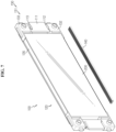
- FIG. 7 is a full perspective view showing a thermal interface material separated from the battery cell frame of FIG. 2
- FIG. 8 is a side cross-sectional view showing the thermal interface material coupled to the battery cell frame in FIG. 7 .
- the thermal interface material (TIM) 140 may be coupled to the second variable length part 135 to transfer heat, and the thermal interface material 140 may come into direct or indirect contact with the battery cell 200.
- the conventional frame has a high error ratio because thermal resin is introduced after assembly of the battery cell 200, but in the case of the battery cell frame 100 according to an embodiment of the present disclosure, when the spiral spring is in expanded state, the thermal interface material 140 is coupled to the spiral spring, for example, around at least a portion of the spiral spring, and thus its effects are high heat dissipation efficiency and reduced error ratio. Additionally, as shown in FIG. 7 , the thermal interface material 140 is cut to the length of the spiral spring in expanded state, and as shown in FIG. 8 , the thermal interface material 140 is formed in an approximately ' ' shape so that it is coupled around the spiral spring of the second variable length part 135, making it easy to install.
- the battery cell frame 100 includes the first variable length part 131 that changes in length in the short side direction of the support member 120, and the second variable length part 135 that changes in length in the long side direction of the support member 120, to achieve length adjustments to fit various sizes of the battery cell 200.
- the first variable length part 131 includes the fixed part 132 that is fixedly coupled to one side of the bus bar 110, and the moveable part 133 that is moveably coupled to the other side of the bus bar 110 at a location facing the fixed part 132 to change the length in the short side direction of the support member 120
- the second variable length part 135 comprises a spiral spring that can shrink and expand to change the length in the long side direction of the support member 120.
- the thermal interface material 140 is coupled around at least a portion of the spiral spring, and thus its effects are high heat dissipation efficiency and reduced error ratio.
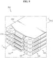
- FIG. 9 is a full perspective view schematically showing the battery module according to an embodiment of the present disclosure
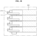
- FIG. 10 is a cross-sectional view taken along the line A-A' of FIG. 9 .
- the electrode lead 210 of the battery cell 200 is electrically coupled to the bus bar 110 of the battery cell frame 100 of the above-described embodiment, and the battery cell 200 is supported in contact with the support member 120 of the battery cell frame 100. Additionally, the plurality of battery cells 200 coupled to the battery cell frame 100 may be stacked one another to form a battery cell stack.
- the battery cell 200 may have the electrode lead 210.
- the electrode lead 210 is a sort of terminal that is exposed to the outside and connected to an external device, and may be made of a conductive material.
- the electrode lead 210 may include a positive electrode lead and a negative electrode lead.
- the positive electrode lead and the negative electrode lead may be placed in opposite directions along the lengthwise direction of the battery cell 200, or the positive electrode lead and the negative electrode lead may be disposed in the same direction along the lengthwise direction of the battery cell 200.
- the electrode lead 210 is electrically coupled to a conducting member of the bus bar 110 as described below.
- a battery pack (not shown) according to an embodiment of the present disclosure may include at least one battery module 300 according to an embodiment of the present disclosure as described above. Additionally, in addition to the battery module 300, the battery pack (not shown) may further include a case for receiving the battery module 300, and various types of devices for controlling the charge/discharge of the battery module 300, for example, a BMS, a current sensor and a fuse.
- the present disclosure relates to a battery cell frame and a battery module including the same, and, in particular, the present disclosure may be applied to industries associated with a secondary battery.
Landscapes
- Chemical & Material Sciences (AREA)
- Chemical Kinetics & Catalysis (AREA)
- Electrochemistry (AREA)
- General Chemical & Material Sciences (AREA)
- Engineering & Computer Science (AREA)
- Manufacturing & Machinery (AREA)
- Materials Engineering (AREA)
- Battery Mounting, Suspending (AREA)
- Connection Of Batteries Or Terminals (AREA)
- Secondary Cells (AREA)
Applications Claiming Priority (2)
| Application Number | Priority Date | Filing Date | Title |
|---|---|---|---|
| KR1020170100477A KR102059651B1 (ko) | 2017-08-08 | 2017-08-08 | 배터리 셀 프레임 및 이를 포함하는 배터리 모듈 |
| PCT/KR2018/006860 WO2019031702A1 (ko) | 2017-08-08 | 2018-06-18 | 배터리 셀 프레임 및 이를 포함하는 배터리 모듈 |
Publications (3)
| Publication Number | Publication Date |
|---|---|
| EP3582286A1 EP3582286A1 (en) | 2019-12-18 |
| EP3582286A4 EP3582286A4 (en) | 2020-05-06 |
| EP3582286B1 true EP3582286B1 (en) | 2023-12-20 |
Family
ID=65271232
Family Applications (1)
| Application Number | Title | Priority Date | Filing Date |
|---|---|---|---|
| EP18845031.6A Active EP3582286B1 (en) | 2017-08-08 | 2018-06-18 | Battery cell frame and battery module comprising same |
Country Status (9)
| Country | Link |
|---|---|
| US (1) | US11139523B2 (pl) |
| EP (1) | EP3582286B1 (pl) |
| JP (1) | JP7038959B2 (pl) |
| KR (1) | KR102059651B1 (pl) |
| CN (2) | CN109390518B (pl) |
| ES (1) | ES2969551T3 (pl) |
| HU (1) | HUE065082T2 (pl) |
| PL (1) | PL3582286T3 (pl) |
| WO (1) | WO2019031702A1 (pl) |
Families Citing this family (10)
| Publication number | Priority date | Publication date | Assignee | Title |
|---|---|---|---|---|
| KR102059651B1 (ko) * | 2017-08-08 | 2019-12-26 | 주식회사 엘지화학 | 배터리 셀 프레임 및 이를 포함하는 배터리 모듈 |
| FR3095301B1 (fr) * | 2019-04-19 | 2021-04-16 | Psa Automobiles Sa | Dispositif de stockage à cellule électrochimique prismatique à inserts de drainage, et batterie associée |
| KR102541537B1 (ko) * | 2019-06-25 | 2023-06-08 | 주식회사 엘지에너지솔루션 | 전지 모듈 및 이를 포함하는 전지팩 |
| KR102791126B1 (ko) * | 2019-09-03 | 2025-04-02 | 주식회사 엘지에너지솔루션 | 길이 조절이 가능한 인터-버스바 |
| DE102020118323B3 (de) | 2020-07-10 | 2021-10-07 | Hans Martin Tekeser e.K. | Längen- und höhenverstellbare Rahmenvorrichtung für die Aufnahme einer Einzelzelle mit zumindest einem mehrteiligen winkelverstellbaren Winkel-Teilelement sowie ein elektrisches Speichermodul umfassend eine Rahmenvorrichtung |
| KR20220026928A (ko) * | 2020-08-26 | 2022-03-07 | 주식회사 엘지에너지솔루션 | 배터리 모듈, 이를 포함하는 배터리 팩 및 자동차 |
| CN112421144B (zh) * | 2020-11-11 | 2022-03-08 | 湖北亿纬动力有限公司 | 电池模组 |
| JP2022182248A (ja) * | 2021-05-28 | 2022-12-08 | 小島プレス工業株式会社 | 電池モジュール |
| CN114723942B (zh) * | 2022-06-08 | 2022-12-20 | 深圳新视智科技术有限公司 | 锂电池极片的尺寸检测方法、装置、设备及存储介质 |
| KR20250118570A (ko) * | 2024-01-30 | 2025-08-06 | 주식회사 엘지에너지솔루션 | 팩 하우징, 배터리 팩 및 이를 포함하는 자동차 |
Family Cites Families (23)
| Publication number | Priority date | Publication date | Assignee | Title |
|---|---|---|---|---|
| CN101483226A (zh) * | 2008-01-08 | 2009-07-15 | 王林生 | 万用手机电池 |
| JP5146092B2 (ja) | 2008-05-09 | 2013-02-20 | 株式会社Gsユアサ | 組電池用スペーサーおよびそれを用いた組電池 |
| KR101050318B1 (ko) * | 2009-04-16 | 2011-07-19 | 에스비리모티브 주식회사 | 이차 전지 모듈 |
| KR101093294B1 (ko) * | 2009-10-26 | 2011-12-14 | 삼성에스디아이 주식회사 | 홀더 케이스 및 이를 구비하는 배터리 팩 |
| KR101146677B1 (ko) * | 2009-10-30 | 2012-05-22 | 에스비리모티브 주식회사 | 버스바홀더 |
| JP2011108377A (ja) * | 2009-11-12 | 2011-06-02 | Hitachi Maxell Ltd | 電池パック及びその製造方法 |
| CN201601160U (zh) * | 2009-11-23 | 2010-10-06 | 湖南三鑫电源科技有限责任公司 | 一种组合式蓄电池防盗架 |
| CN201904384U (zh) * | 2010-10-26 | 2011-07-20 | 康佳集团股份有限公司 | 一种手机及其电池框 |
| KR101300110B1 (ko) | 2011-08-17 | 2013-08-30 | 주식회사 엘지화학 | 케이블형 이차전지 |
| JP2013254642A (ja) * | 2012-06-07 | 2013-12-19 | Niikura Keiryoki Kk | 電池収容装置 |
| KR101732285B1 (ko) | 2012-11-09 | 2017-05-02 | 닛산 지도우샤 가부시키가이샤 | 조전지 및 조전지의 제조 방법 |
| JP2014203763A (ja) | 2013-04-09 | 2014-10-27 | 日産自動車株式会社 | 電池パックの温度調節構造 |
| KR20150095297A (ko) * | 2014-02-13 | 2015-08-21 | (주)탑전지 | 단위 전지 및 이를 포함하는 전지팩 |
| KR101565115B1 (ko) | 2014-03-31 | 2015-11-02 | (주)탑전지 | 배터리 팩 및 그 제조 방법 |
| KR101728006B1 (ko) * | 2014-05-22 | 2017-04-18 | 주식회사 엘지화학 | 가변 연신부를 포함하는 전지 케이스 |
| JP6373103B2 (ja) * | 2014-07-18 | 2018-08-15 | カルソニックカンセイ株式会社 | 蓄電装置 |
| KR102210461B1 (ko) | 2014-07-23 | 2021-02-01 | 에스케이이노베이션 주식회사 | 단위전지모듈과 이를 포함하는 전지모듈 및 전지모듈의 제조방법과 이를 포함하는 전지팩 |
| JP6260487B2 (ja) | 2014-07-31 | 2018-01-17 | 株式会社Gsユアサ | 蓄電装置 |
| JP6274052B2 (ja) | 2014-09-04 | 2018-02-07 | 株式会社Gsユアサ | 蓄電装置 |
| JP6628472B2 (ja) | 2014-12-25 | 2020-01-08 | 藤森工業株式会社 | 非水系電池外装用積層体 |
| CN204464344U (zh) | 2015-02-13 | 2015-07-08 | 上海闻泰电子科技有限公司 | 测试用手机假电池 |
| KR102080902B1 (ko) * | 2015-12-07 | 2020-02-24 | 주식회사 엘지화학 | 배터리 모듈 및 이를 포함하는 배터리 팩 |
| KR102059651B1 (ko) * | 2017-08-08 | 2019-12-26 | 주식회사 엘지화학 | 배터리 셀 프레임 및 이를 포함하는 배터리 모듈 |
-
2017
- 2017-08-08 KR KR1020170100477A patent/KR102059651B1/ko active Active
-
2018
- 2018-06-18 WO PCT/KR2018/006860 patent/WO2019031702A1/ko not_active Ceased
- 2018-06-18 ES ES18845031T patent/ES2969551T3/es active Active
- 2018-06-18 EP EP18845031.6A patent/EP3582286B1/en active Active
- 2018-06-18 PL PL18845031.6T patent/PL3582286T3/pl unknown
- 2018-06-18 JP JP2019541340A patent/JP7038959B2/ja active Active
- 2018-06-18 US US16/482,874 patent/US11139523B2/en active Active
- 2018-06-18 HU HUE18845031A patent/HUE065082T2/hu unknown
- 2018-08-07 CN CN201810888996.2A patent/CN109390518B/zh active Active
- 2018-08-07 CN CN201821264130.6U patent/CN208522015U/zh active Active
Also Published As
| Publication number | Publication date |
|---|---|
| US20190355947A1 (en) | 2019-11-21 |
| CN109390518B (zh) | 2020-11-03 |
| KR102059651B1 (ko) | 2019-12-26 |
| HUE065082T2 (hu) | 2024-04-28 |
| EP3582286A1 (en) | 2019-12-18 |
| WO2019031702A1 (ko) | 2019-02-14 |
| PL3582286T3 (pl) | 2024-03-18 |
| CN208522015U (zh) | 2019-02-19 |
| JP7038959B2 (ja) | 2022-03-22 |
| CN109390518A (zh) | 2019-02-26 |
| JP2020507184A (ja) | 2020-03-05 |
| ES2969551T3 (es) | 2024-05-21 |
| EP3582286A4 (en) | 2020-05-06 |
| KR20190016353A (ko) | 2019-02-18 |
| US11139523B2 (en) | 2021-10-05 |
Similar Documents
| Publication | Publication Date | Title |
|---|---|---|
| EP3582286B1 (en) | Battery cell frame and battery module comprising same | |
| EP3614453B1 (en) | Battery module and battery pack including same | |
| US11923564B2 (en) | Method for producing battery module | |
| EP4152503B1 (en) | Battery pack and vehicle comprising same | |
| EP3540817B1 (en) | Battery pack | |
| US11031650B2 (en) | Battery module and battery pack comprising same | |
| US11152671B2 (en) | Battery module and battery pack including the same | |
| EP3419083A1 (en) | Cylindrical secondary battery module | |
| CN108463901A (zh) | 电池模块和包括该电池模块的电池组 | |
| KR20190007745A (ko) | 배터리 팩 | |
| EP4053988A1 (en) | Battery module provided with rail-type socket and battery pack comprising same | |
| EP4258425A1 (en) | Battery module, and battery pack and vehicle comprising same | |
| EP4283775A1 (en) | Battery pack and vehicle including same | |
| JP7460773B2 (ja) | バッテリーモジュール、それを含むバッテリーパック及び自動車 | |
| KR102714029B1 (ko) | 배터리 모듈, 이를 포함하는 배터리 팩 및 자동차 |
Legal Events
| Date | Code | Title | Description |
|---|---|---|---|
| STAA | Information on the status of an ep patent application or granted ep patent |
Free format text: STATUS: THE INTERNATIONAL PUBLICATION HAS BEEN MADE |
|
| PUAI | Public reference made under article 153(3) epc to a published international application that has entered the european phase |
Free format text: ORIGINAL CODE: 0009012 |
|
| STAA | Information on the status of an ep patent application or granted ep patent |
Free format text: STATUS: REQUEST FOR EXAMINATION WAS MADE |
|
| 17P | Request for examination filed |
Effective date: 20190912 |
|
| AK | Designated contracting states |
Kind code of ref document: A1 Designated state(s): AL AT BE BG CH CY CZ DE DK EE ES FI FR GB GR HR HU IE IS IT LI LT LU LV MC MK MT NL NO PL PT RO RS SE SI SK SM TR |
|
| AX | Request for extension of the european patent |
Extension state: BA ME |
|
| A4 | Supplementary search report drawn up and despatched |
Effective date: 20200403 |
|
| RIC1 | Information provided on ipc code assigned before grant |
Ipc: H01M 10/655 20140101ALI20200330BHEP Ipc: H01M 2/10 20060101AFI20200330BHEP Ipc: H01M 2/02 20060101ALI20200330BHEP Ipc: H01M 10/04 20060101ALI20200330BHEP Ipc: H01M 10/058 20100101ALI20200330BHEP Ipc: H01M 2/20 20060101ALI20200330BHEP Ipc: H01M 10/0525 20100101ALI20200330BHEP |
|
| DAV | Request for validation of the european patent (deleted) | ||
| DAX | Request for extension of the european patent (deleted) | ||
| RAP1 | Party data changed (applicant data changed or rights of an application transferred) |
Owner name: LG ENERGY SOLUTION LTD. |
|
| RAP3 | Party data changed (applicant data changed or rights of an application transferred) |
Owner name: LG ENERGY SOLUTION, LTD. |
|
| STAA | Information on the status of an ep patent application or granted ep patent |
Free format text: STATUS: EXAMINATION IS IN PROGRESS |
|
| 17Q | First examination report despatched |
Effective date: 20221010 |
|
| REG | Reference to a national code |
Ref country code: DE Ref legal event code: R079 Free format text: PREVIOUS MAIN CLASS: H01M0002100000 Ipc: H01M0010052500 Ref country code: DE Ref legal event code: R079 Ref document number: 602018063003 Country of ref document: DE Free format text: PREVIOUS MAIN CLASS: H01M0002100000 Ipc: H01M0010052500 |
|
| RIC1 | Information provided on ipc code assigned before grant |
Ipc: H01M 50/202 20210101ALI20230814BHEP Ipc: H01M 50/548 20210101ALI20230814BHEP Ipc: H01M 50/503 20210101ALI20230814BHEP Ipc: H01M 50/50 20210101ALI20230814BHEP Ipc: H01M 50/103 20210101ALI20230814BHEP Ipc: H01M 10/655 20140101ALI20230814BHEP Ipc: H01M 10/04 20060101ALI20230814BHEP Ipc: H01M 10/058 20100101ALI20230814BHEP Ipc: H01M 10/0525 20100101AFI20230814BHEP |
|
| GRAP | Despatch of communication of intention to grant a patent |
Free format text: ORIGINAL CODE: EPIDOSNIGR1 |
|
| STAA | Information on the status of an ep patent application or granted ep patent |
Free format text: STATUS: GRANT OF PATENT IS INTENDED |
|
| INTG | Intention to grant announced |
Effective date: 20230925 |
|
| GRAS | Grant fee paid |
Free format text: ORIGINAL CODE: EPIDOSNIGR3 |
|
| GRAA | (expected) grant |
Free format text: ORIGINAL CODE: 0009210 |
|
| STAA | Information on the status of an ep patent application or granted ep patent |
Free format text: STATUS: THE PATENT HAS BEEN GRANTED |
|
| AK | Designated contracting states |
Kind code of ref document: B1 Designated state(s): AL AT BE BG CH CY CZ DE DK EE ES FI FR GB GR HR HU IE IS IT LI LT LU LV MC MK MT NL NO PL PT RO RS SE SI SK SM TR |
|
| REG | Reference to a national code |
Ref country code: GB Ref legal event code: FG4D |
|
| REG | Reference to a national code |
Ref country code: CH Ref legal event code: EP |
|
| REG | Reference to a national code |
Ref country code: DE Ref legal event code: R096 Ref document number: 602018063003 Country of ref document: DE |
|
| P01 | Opt-out of the competence of the unified patent court (upc) registered |
Effective date: 20231208 |
|
| REG | Reference to a national code |
Ref country code: IE Ref legal event code: FG4D |
|
| REG | Reference to a national code |
Ref country code: NL Ref legal event code: FP |
|
| REG | Reference to a national code |
Ref country code: SE Ref legal event code: TRGR |
|
| PG25 | Lapsed in a contracting state [announced via postgrant information from national office to epo] |
Ref country code: GR Free format text: LAPSE BECAUSE OF FAILURE TO SUBMIT A TRANSLATION OF THE DESCRIPTION OR TO PAY THE FEE WITHIN THE PRESCRIBED TIME-LIMIT Effective date: 20240321 |
|
| REG | Reference to a national code |
Ref country code: LT Ref legal event code: MG9D |
|
| PG25 | Lapsed in a contracting state [announced via postgrant information from national office to epo] |
Ref country code: LT Free format text: LAPSE BECAUSE OF FAILURE TO SUBMIT A TRANSLATION OF THE DESCRIPTION OR TO PAY THE FEE WITHIN THE PRESCRIBED TIME-LIMIT Effective date: 20231220 |
|
| REG | Reference to a national code |
Ref country code: HU Ref legal event code: AG4A Ref document number: E065082 Country of ref document: HU |
|
| PG25 | Lapsed in a contracting state [announced via postgrant information from national office to epo] |
Ref country code: LT Free format text: LAPSE BECAUSE OF FAILURE TO SUBMIT A TRANSLATION OF THE DESCRIPTION OR TO PAY THE FEE WITHIN THE PRESCRIBED TIME-LIMIT Effective date: 20231220 Ref country code: GR Free format text: LAPSE BECAUSE OF FAILURE TO SUBMIT A TRANSLATION OF THE DESCRIPTION OR TO PAY THE FEE WITHIN THE PRESCRIBED TIME-LIMIT Effective date: 20240321 Ref country code: FI Free format text: LAPSE BECAUSE OF FAILURE TO SUBMIT A TRANSLATION OF THE DESCRIPTION OR TO PAY THE FEE WITHIN THE PRESCRIBED TIME-LIMIT Effective date: 20231220 Ref country code: BG Free format text: LAPSE BECAUSE OF FAILURE TO SUBMIT A TRANSLATION OF THE DESCRIPTION OR TO PAY THE FEE WITHIN THE PRESCRIBED TIME-LIMIT Effective date: 20240320 |
|
| REG | Reference to a national code |
Ref country code: AT Ref legal event code: MK05 Ref document number: 1643239 Country of ref document: AT Kind code of ref document: T Effective date: 20231220 |
|
| REG | Reference to a national code |
Ref country code: ES Ref legal event code: FG2A Ref document number: 2969551 Country of ref document: ES Kind code of ref document: T3 Effective date: 20240521 |
|
| PG25 | Lapsed in a contracting state [announced via postgrant information from national office to epo] |
Ref country code: RS Free format text: LAPSE BECAUSE OF FAILURE TO SUBMIT A TRANSLATION OF THE DESCRIPTION OR TO PAY THE FEE WITHIN THE PRESCRIBED TIME-LIMIT Effective date: 20231220 Ref country code: NO Free format text: LAPSE BECAUSE OF FAILURE TO SUBMIT A TRANSLATION OF THE DESCRIPTION OR TO PAY THE FEE WITHIN THE PRESCRIBED TIME-LIMIT Effective date: 20240320 Ref country code: LV Free format text: LAPSE BECAUSE OF FAILURE TO SUBMIT A TRANSLATION OF THE DESCRIPTION OR TO PAY THE FEE WITHIN THE PRESCRIBED TIME-LIMIT Effective date: 20231220 Ref country code: HR Free format text: LAPSE BECAUSE OF FAILURE TO SUBMIT A TRANSLATION OF THE DESCRIPTION OR TO PAY THE FEE WITHIN THE PRESCRIBED TIME-LIMIT Effective date: 20231220 |
|
| PG25 | Lapsed in a contracting state [announced via postgrant information from national office to epo] |
Ref country code: IS Free format text: LAPSE BECAUSE OF FAILURE TO SUBMIT A TRANSLATION OF THE DESCRIPTION OR TO PAY THE FEE WITHIN THE PRESCRIBED TIME-LIMIT Effective date: 20240420 |
|
| PG25 | Lapsed in a contracting state [announced via postgrant information from national office to epo] |
Ref country code: AT Free format text: LAPSE BECAUSE OF FAILURE TO SUBMIT A TRANSLATION OF THE DESCRIPTION OR TO PAY THE FEE WITHIN THE PRESCRIBED TIME-LIMIT Effective date: 20231220 Ref country code: CZ Free format text: LAPSE BECAUSE OF FAILURE TO SUBMIT A TRANSLATION OF THE DESCRIPTION OR TO PAY THE FEE WITHIN THE PRESCRIBED TIME-LIMIT Effective date: 20231220 |
|
| PG25 | Lapsed in a contracting state [announced via postgrant information from national office to epo] |
Ref country code: SK Free format text: LAPSE BECAUSE OF FAILURE TO SUBMIT A TRANSLATION OF THE DESCRIPTION OR TO PAY THE FEE WITHIN THE PRESCRIBED TIME-LIMIT Effective date: 20231220 |
|
| PG25 | Lapsed in a contracting state [announced via postgrant information from national office to epo] |
Ref country code: SM Free format text: LAPSE BECAUSE OF FAILURE TO SUBMIT A TRANSLATION OF THE DESCRIPTION OR TO PAY THE FEE WITHIN THE PRESCRIBED TIME-LIMIT Effective date: 20231220 Ref country code: SK Free format text: LAPSE BECAUSE OF FAILURE TO SUBMIT A TRANSLATION OF THE DESCRIPTION OR TO PAY THE FEE WITHIN THE PRESCRIBED TIME-LIMIT Effective date: 20231220 Ref country code: RO Free format text: LAPSE BECAUSE OF FAILURE TO SUBMIT A TRANSLATION OF THE DESCRIPTION OR TO PAY THE FEE WITHIN THE PRESCRIBED TIME-LIMIT Effective date: 20231220 Ref country code: IS Free format text: LAPSE BECAUSE OF FAILURE TO SUBMIT A TRANSLATION OF THE DESCRIPTION OR TO PAY THE FEE WITHIN THE PRESCRIBED TIME-LIMIT Effective date: 20240420 Ref country code: EE Free format text: LAPSE BECAUSE OF FAILURE TO SUBMIT A TRANSLATION OF THE DESCRIPTION OR TO PAY THE FEE WITHIN THE PRESCRIBED TIME-LIMIT Effective date: 20231220 Ref country code: CZ Free format text: LAPSE BECAUSE OF FAILURE TO SUBMIT A TRANSLATION OF THE DESCRIPTION OR TO PAY THE FEE WITHIN THE PRESCRIBED TIME-LIMIT Effective date: 20231220 Ref country code: AT Free format text: LAPSE BECAUSE OF FAILURE TO SUBMIT A TRANSLATION OF THE DESCRIPTION OR TO PAY THE FEE WITHIN THE PRESCRIBED TIME-LIMIT Effective date: 20231220 |
|
| PG25 | Lapsed in a contracting state [announced via postgrant information from national office to epo] |
Ref country code: PT Free format text: LAPSE BECAUSE OF FAILURE TO SUBMIT A TRANSLATION OF THE DESCRIPTION OR TO PAY THE FEE WITHIN THE PRESCRIBED TIME-LIMIT Effective date: 20240422 |
|
| PG25 | Lapsed in a contracting state [announced via postgrant information from national office to epo] |
Ref country code: PT Free format text: LAPSE BECAUSE OF FAILURE TO SUBMIT A TRANSLATION OF THE DESCRIPTION OR TO PAY THE FEE WITHIN THE PRESCRIBED TIME-LIMIT Effective date: 20240422 |
|
| REG | Reference to a national code |
Ref country code: DE Ref legal event code: R097 Ref document number: 602018063003 Country of ref document: DE |
|
| PG25 | Lapsed in a contracting state [announced via postgrant information from national office to epo] |
Ref country code: DK Free format text: LAPSE BECAUSE OF FAILURE TO SUBMIT A TRANSLATION OF THE DESCRIPTION OR TO PAY THE FEE WITHIN THE PRESCRIBED TIME-LIMIT Effective date: 20231220 |
|
| PLBE | No opposition filed within time limit |
Free format text: ORIGINAL CODE: 0009261 |
|
| STAA | Information on the status of an ep patent application or granted ep patent |
Free format text: STATUS: NO OPPOSITION FILED WITHIN TIME LIMIT |
|
| PG25 | Lapsed in a contracting state [announced via postgrant information from national office to epo] |
Ref country code: SI Free format text: LAPSE BECAUSE OF FAILURE TO SUBMIT A TRANSLATION OF THE DESCRIPTION OR TO PAY THE FEE WITHIN THE PRESCRIBED TIME-LIMIT Effective date: 20231220 |
|
| PG25 | Lapsed in a contracting state [announced via postgrant information from national office to epo] |
Ref country code: SI Free format text: LAPSE BECAUSE OF FAILURE TO SUBMIT A TRANSLATION OF THE DESCRIPTION OR TO PAY THE FEE WITHIN THE PRESCRIBED TIME-LIMIT Effective date: 20231220 Ref country code: DK Free format text: LAPSE BECAUSE OF FAILURE TO SUBMIT A TRANSLATION OF THE DESCRIPTION OR TO PAY THE FEE WITHIN THE PRESCRIBED TIME-LIMIT Effective date: 20231220 |
|
| 26N | No opposition filed |
Effective date: 20240923 |
|
| PG25 | Lapsed in a contracting state [announced via postgrant information from national office to epo] |
Ref country code: MC Free format text: LAPSE BECAUSE OF FAILURE TO SUBMIT A TRANSLATION OF THE DESCRIPTION OR TO PAY THE FEE WITHIN THE PRESCRIBED TIME-LIMIT Effective date: 20231220 |
|
| REG | Reference to a national code |
Ref country code: CH Ref legal event code: PL |
|
| PG25 | Lapsed in a contracting state [announced via postgrant information from national office to epo] |
Ref country code: LU Free format text: LAPSE BECAUSE OF NON-PAYMENT OF DUE FEES Effective date: 20240618 |
|
| PG25 | Lapsed in a contracting state [announced via postgrant information from national office to epo] |
Ref country code: IE Free format text: LAPSE BECAUSE OF NON-PAYMENT OF DUE FEES Effective date: 20240618 |
|
| PG25 | Lapsed in a contracting state [announced via postgrant information from national office to epo] |
Ref country code: BE Free format text: LAPSE BECAUSE OF NON-PAYMENT OF DUE FEES Effective date: 20240630 Ref country code: CH Free format text: LAPSE BECAUSE OF NON-PAYMENT OF DUE FEES Effective date: 20240630 |
|
| REG | Reference to a national code |
Ref country code: BE Ref legal event code: MM Effective date: 20240630 |
|
| PGFP | Annual fee paid to national office [announced via postgrant information from national office to epo] |
Ref country code: NL Payment date: 20250520 Year of fee payment: 8 |
|
| PGFP | Annual fee paid to national office [announced via postgrant information from national office to epo] |
Ref country code: PL Payment date: 20250521 Year of fee payment: 8 Ref country code: DE Payment date: 20250520 Year of fee payment: 8 |
|
| PGFP | Annual fee paid to national office [announced via postgrant information from national office to epo] |
Ref country code: GB Payment date: 20250520 Year of fee payment: 8 |
|
| PGFP | Annual fee paid to national office [announced via postgrant information from national office to epo] |
Ref country code: IT Payment date: 20250523 Year of fee payment: 8 |
|
| PGFP | Annual fee paid to national office [announced via postgrant information from national office to epo] |
Ref country code: FR Payment date: 20250521 Year of fee payment: 8 Ref country code: HU Payment date: 20250623 Year of fee payment: 8 |
|
| PGFP | Annual fee paid to national office [announced via postgrant information from national office to epo] |
Ref country code: TR Payment date: 20250523 Year of fee payment: 8 |
|
| PGFP | Annual fee paid to national office [announced via postgrant information from national office to epo] |
Ref country code: SE Payment date: 20250523 Year of fee payment: 8 |
|
| PGFP | Annual fee paid to national office [announced via postgrant information from national office to epo] |
Ref country code: ES Payment date: 20250714 Year of fee payment: 8 |
|
| PG25 | Lapsed in a contracting state [announced via postgrant information from national office to epo] |
Ref country code: CY Free format text: LAPSE BECAUSE OF FAILURE TO SUBMIT A TRANSLATION OF THE DESCRIPTION OR TO PAY THE FEE WITHIN THE PRESCRIBED TIME-LIMIT; INVALID AB INITIO Effective date: 20180618 |