EP4283775A1 - Battery pack and vehicle including same - Google Patents
Battery pack and vehicle including same Download PDFInfo
- Publication number
- EP4283775A1 EP4283775A1 EP22842405.7A EP22842405A EP4283775A1 EP 4283775 A1 EP4283775 A1 EP 4283775A1 EP 22842405 A EP22842405 A EP 22842405A EP 4283775 A1 EP4283775 A1 EP 4283775A1
- Authority
- EP
- European Patent Office
- Prior art keywords
- busbar
- battery pack
- heat dissipation
- bolt
- battery
- Prior art date
- Legal status (The legal status is an assumption and is not a legal conclusion. Google has not performed a legal analysis and makes no representation as to the accuracy of the status listed.)
- Pending
Links
- 230000017525 heat dissipation Effects 0.000 claims abstract description 46
- 229910010293 ceramic material Inorganic materials 0.000 claims description 7
- 238000010292 electrical insulation Methods 0.000 claims description 4
- WHXSMMKQMYFTQS-UHFFFAOYSA-N Lithium Chemical compound [Li] WHXSMMKQMYFTQS-UHFFFAOYSA-N 0.000 description 6
- 229910052744 lithium Inorganic materials 0.000 description 6
- 230000005611 electricity Effects 0.000 description 4
- 239000007773 negative electrode material Substances 0.000 description 4
- 239000007774 positive electrode material Substances 0.000 description 4
- 238000010168 coupling process Methods 0.000 description 3
- 239000000463 material Substances 0.000 description 3
- HBBGRARXTFLTSG-UHFFFAOYSA-N Lithium ion Chemical compound [Li+] HBBGRARXTFLTSG-UHFFFAOYSA-N 0.000 description 2
- PXHVJJICTQNCMI-UHFFFAOYSA-N Nickel Chemical compound [Ni] PXHVJJICTQNCMI-UHFFFAOYSA-N 0.000 description 2
- 230000008878 coupling Effects 0.000 description 2
- 238000005859 coupling reaction Methods 0.000 description 2
- 230000000694 effects Effects 0.000 description 2
- 229910001416 lithium ion Inorganic materials 0.000 description 2
- 238000012986 modification Methods 0.000 description 2
- 230000004048 modification Effects 0.000 description 2
- RYGMFSIKBFXOCR-UHFFFAOYSA-N Copper Chemical compound [Cu] RYGMFSIKBFXOCR-UHFFFAOYSA-N 0.000 description 1
- 229910052782 aluminium Inorganic materials 0.000 description 1
- XAGFODPZIPBFFR-UHFFFAOYSA-N aluminium Chemical compound [Al] XAGFODPZIPBFFR-UHFFFAOYSA-N 0.000 description 1
- 238000005452 bending Methods 0.000 description 1
- 230000008901 benefit Effects 0.000 description 1
- OJIJEKBXJYRIBZ-UHFFFAOYSA-N cadmium nickel Chemical compound [Ni].[Cd] OJIJEKBXJYRIBZ-UHFFFAOYSA-N 0.000 description 1
- 239000003575 carbonaceous material Substances 0.000 description 1
- 239000000919 ceramic Substances 0.000 description 1
- 239000004020 conductor Substances 0.000 description 1
- 229910052802 copper Inorganic materials 0.000 description 1
- 239000010949 copper Substances 0.000 description 1
- 238000001035 drying Methods 0.000 description 1
- 239000003792 electrolyte Substances 0.000 description 1
- 239000008151 electrolyte solution Substances 0.000 description 1
- 238000005516 engineering process Methods 0.000 description 1
- 239000011888 foil Substances 0.000 description 1
- 230000006870 function Effects 0.000 description 1
- GPRLSGONYQIRFK-UHFFFAOYSA-N hydron Chemical compound [H+] GPRLSGONYQIRFK-UHFFFAOYSA-N 0.000 description 1
- 238000001746 injection moulding Methods 0.000 description 1
- 238000009413 insulation Methods 0.000 description 1
- 230000003446 memory effect Effects 0.000 description 1
- 229910052751 metal Inorganic materials 0.000 description 1
- 239000002184 metal Substances 0.000 description 1
- 238000000034 method Methods 0.000 description 1
- 229910052759 nickel Inorganic materials 0.000 description 1
- 238000004806 packaging method and process Methods 0.000 description 1
- 239000004033 plastic Substances 0.000 description 1
- 229920000642 polymer Polymers 0.000 description 1
- 239000000243 solution Substances 0.000 description 1
Images


Classifications
-
- H—ELECTRICITY
- H01—ELECTRIC ELEMENTS
- H01M—PROCESSES OR MEANS, e.g. BATTERIES, FOR THE DIRECT CONVERSION OF CHEMICAL ENERGY INTO ELECTRICAL ENERGY
- H01M50/00—Constructional details or processes of manufacture of the non-active parts of electrochemical cells other than fuel cells, e.g. hybrid cells
- H01M50/50—Current conducting connections for cells or batteries
- H01M50/502—Interconnectors for connecting terminals of adjacent batteries; Interconnectors for connecting cells outside a battery casing
- H01M50/514—Methods for interconnecting adjacent batteries or cells
- H01M50/517—Methods for interconnecting adjacent batteries or cells by fixing means, e.g. screws, rivets or bolts
-
- H—ELECTRICITY
- H01—ELECTRIC ELEMENTS
- H01M—PROCESSES OR MEANS, e.g. BATTERIES, FOR THE DIRECT CONVERSION OF CHEMICAL ENERGY INTO ELECTRICAL ENERGY
- H01M10/00—Secondary cells; Manufacture thereof
- H01M10/60—Heating or cooling; Temperature control
- H01M10/61—Types of temperature control
- H01M10/613—Cooling or keeping cold
-
- H—ELECTRICITY
- H01—ELECTRIC ELEMENTS
- H01M—PROCESSES OR MEANS, e.g. BATTERIES, FOR THE DIRECT CONVERSION OF CHEMICAL ENERGY INTO ELECTRICAL ENERGY
- H01M10/00—Secondary cells; Manufacture thereof
- H01M10/60—Heating or cooling; Temperature control
- H01M10/62—Heating or cooling; Temperature control specially adapted for specific applications
- H01M10/625—Vehicles
-
- H—ELECTRICITY
- H01—ELECTRIC ELEMENTS
- H01M—PROCESSES OR MEANS, e.g. BATTERIES, FOR THE DIRECT CONVERSION OF CHEMICAL ENERGY INTO ELECTRICAL ENERGY
- H01M10/00—Secondary cells; Manufacture thereof
- H01M10/60—Heating or cooling; Temperature control
- H01M10/65—Means for temperature control structurally associated with the cells
- H01M10/653—Means for temperature control structurally associated with the cells characterised by electrically insulating or thermally conductive materials
-
- H—ELECTRICITY
- H01—ELECTRIC ELEMENTS
- H01M—PROCESSES OR MEANS, e.g. BATTERIES, FOR THE DIRECT CONVERSION OF CHEMICAL ENERGY INTO ELECTRICAL ENERGY
- H01M10/00—Secondary cells; Manufacture thereof
- H01M10/60—Heating or cooling; Temperature control
- H01M10/65—Means for temperature control structurally associated with the cells
- H01M10/655—Solid structures for heat exchange or heat conduction
- H01M10/6553—Terminals or leads
-
- H—ELECTRICITY
- H01—ELECTRIC ELEMENTS
- H01M—PROCESSES OR MEANS, e.g. BATTERIES, FOR THE DIRECT CONVERSION OF CHEMICAL ENERGY INTO ELECTRICAL ENERGY
- H01M10/00—Secondary cells; Manufacture thereof
- H01M10/60—Heating or cooling; Temperature control
- H01M10/65—Means for temperature control structurally associated with the cells
- H01M10/655—Solid structures for heat exchange or heat conduction
- H01M10/6554—Rods or plates
-
- H—ELECTRICITY
- H01—ELECTRIC ELEMENTS
- H01M—PROCESSES OR MEANS, e.g. BATTERIES, FOR THE DIRECT CONVERSION OF CHEMICAL ENERGY INTO ELECTRICAL ENERGY
- H01M10/00—Secondary cells; Manufacture thereof
- H01M10/60—Heating or cooling; Temperature control
- H01M10/65—Means for temperature control structurally associated with the cells
- H01M10/658—Means for temperature control structurally associated with the cells by thermal insulation or shielding
-
- H—ELECTRICITY
- H01—ELECTRIC ELEMENTS
- H01M—PROCESSES OR MEANS, e.g. BATTERIES, FOR THE DIRECT CONVERSION OF CHEMICAL ENERGY INTO ELECTRICAL ENERGY
- H01M50/00—Constructional details or processes of manufacture of the non-active parts of electrochemical cells other than fuel cells, e.g. hybrid cells
- H01M50/20—Mountings; Secondary casings or frames; Racks, modules or packs; Suspension devices; Shock absorbers; Transport or carrying devices; Holders
- H01M50/204—Racks, modules or packs for multiple batteries or multiple cells
- H01M50/207—Racks, modules or packs for multiple batteries or multiple cells characterised by their shape
- H01M50/213—Racks, modules or packs for multiple batteries or multiple cells characterised by their shape adapted for cells having curved cross-section, e.g. round or elliptic
-
- H—ELECTRICITY
- H01—ELECTRIC ELEMENTS
- H01M—PROCESSES OR MEANS, e.g. BATTERIES, FOR THE DIRECT CONVERSION OF CHEMICAL ENERGY INTO ELECTRICAL ENERGY
- H01M50/00—Constructional details or processes of manufacture of the non-active parts of electrochemical cells other than fuel cells, e.g. hybrid cells
- H01M50/20—Mountings; Secondary casings or frames; Racks, modules or packs; Suspension devices; Shock absorbers; Transport or carrying devices; Holders
- H01M50/249—Mountings; Secondary casings or frames; Racks, modules or packs; Suspension devices; Shock absorbers; Transport or carrying devices; Holders specially adapted for aircraft or vehicles, e.g. cars or trains
-
- H—ELECTRICITY
- H01—ELECTRIC ELEMENTS
- H01M—PROCESSES OR MEANS, e.g. BATTERIES, FOR THE DIRECT CONVERSION OF CHEMICAL ENERGY INTO ELECTRICAL ENERGY
- H01M50/00—Constructional details or processes of manufacture of the non-active parts of electrochemical cells other than fuel cells, e.g. hybrid cells
- H01M50/50—Current conducting connections for cells or batteries
- H01M50/502—Interconnectors for connecting terminals of adjacent batteries; Interconnectors for connecting cells outside a battery casing
- H01M50/505—Interconnectors for connecting terminals of adjacent batteries; Interconnectors for connecting cells outside a battery casing comprising a single busbar
-
- H—ELECTRICITY
- H01—ELECTRIC ELEMENTS
- H01M—PROCESSES OR MEANS, e.g. BATTERIES, FOR THE DIRECT CONVERSION OF CHEMICAL ENERGY INTO ELECTRICAL ENERGY
- H01M50/00—Constructional details or processes of manufacture of the non-active parts of electrochemical cells other than fuel cells, e.g. hybrid cells
- H01M50/50—Current conducting connections for cells or batteries
- H01M50/502—Interconnectors for connecting terminals of adjacent batteries; Interconnectors for connecting cells outside a battery casing
- H01M50/521—Interconnectors for connecting terminals of adjacent batteries; Interconnectors for connecting cells outside a battery casing characterised by the material
- H01M50/522—Inorganic material
-
- H—ELECTRICITY
- H01—ELECTRIC ELEMENTS
- H01M—PROCESSES OR MEANS, e.g. BATTERIES, FOR THE DIRECT CONVERSION OF CHEMICAL ENERGY INTO ELECTRICAL ENERGY
- H01M2220/00—Batteries for particular applications
- H01M2220/20—Batteries in motive systems, e.g. vehicle, ship, plane
-
- Y—GENERAL TAGGING OF NEW TECHNOLOGICAL DEVELOPMENTS; GENERAL TAGGING OF CROSS-SECTIONAL TECHNOLOGIES SPANNING OVER SEVERAL SECTIONS OF THE IPC; TECHNICAL SUBJECTS COVERED BY FORMER USPC CROSS-REFERENCE ART COLLECTIONS [XRACs] AND DIGESTS
- Y02—TECHNOLOGIES OR APPLICATIONS FOR MITIGATION OR ADAPTATION AGAINST CLIMATE CHANGE
- Y02E—REDUCTION OF GREENHOUSE GAS [GHG] EMISSIONS, RELATED TO ENERGY GENERATION, TRANSMISSION OR DISTRIBUTION
- Y02E60/00—Enabling technologies; Technologies with a potential or indirect contribution to GHG emissions mitigation
- Y02E60/10—Energy storage using batteries
Definitions
- the present disclosure relates to a battery pack and a vehicle comprising the same, and more particularly, to a battery pack including a busbar unit capable of heat dissipation and a vehicle comprising the same.
- a lithium secondary battery usually uses a lithium-based oxide and a carbon material for a positive electrode active material and a negative electrode active material, respectively.
- the lithium secondary battery includes an electrode assembly including a positive electrode plate and a negative electrode plate coated with the positive electrode active material and the negative electrode active material, respectively, with a separator interposed between the positive electrode plate and the negative electrode plate, and a packaging or a battery case in which the electrode assembly is hermetically received together with an electrolyte solution.
- the lithium secondary battery includes positive and negative electrodes and the separator and the electrolyte interposed between them, and is classified into a Lithium Ion Battery (LIB) and a Polymer Lithium Ion Battery (PLIB) according to the types of the positive and negative electrode active materials.
- LIB Lithium Ion Battery
- PLIB Polymer Lithium Ion Battery
- the electrode of the lithium secondary battery may be formed by applying the positive or negative electrode active material to a current collector of an aluminum or copper sheet, mesh, film, foil and drying.
- a battery pack may include a busbar connected to a battery module to operate an object such as a vehicle, and another busbar connected to the battery module to charge the battery module.
- the present disclosure is directed to providing a battery pack including a busbar unit capable of heat dissipation to reduce the cross-sectional area of the busbar and reduce the size and cost of the battery pack and a vehicle comprising the same.
- a battery pack including a battery module including a plurality of battery cells; a case in which the battery module is received; and a busbar unit connected to the battery module, wherein the busbar unit is used for electrical connection and heat dissipation.
- the busbar unit may include a first busbar member to connect an object to the battery module to operate the object; a second busbar member to connect the battery module to a charging member for charging the battery module; and an insulating heat dissipation member to connect the first busbar member to the second busbar member, and used for electrical insulation and heat transfer.
- the battery pack may further include a relay member coupled to the busbar unit; and a fastening member to fasten the busbar unit to the relay member, the first busbar member and the second busbar member may be disposed on the relay member, and the insulating heat dissipation member may be disposed above the first busbar member and the second busbar member.
- the relay member may include a first relay member coupled to the first busbar member and a second relay member coupled to the second busbar member
- the fastening member may include a first fastening member coupled to the first busbar member and a second fastening mmeber coupled to the second busbar member
- the first busbar member and the first relay member may be fastened to a first end of the insulating heat dissipation member by the first fastening member
- the second busbar member and the second relay member may be fastened to a second end of the insulating heat dissipation member by the second fastening member.
- the insulating heat dissipation member may be H-shaped.
- the insulating heat dissipation member may be made of a ceramic material.
- the fastening member may be a bolt, and a rubber ring may be interposed between the bolt and the insulating heat dissipation member.
- the fastening member may be a bolt
- the battery pack may include a bushing member into which the bolt is inserted.
- the bushing member may include a body having a hollow into which the bolt is inserted; and protrusions which protrude from the body toward the bolt and come into contact with the bolt.
- the body may have a plurality of through-hole shaped cut portions between the protrusions.
- a buffer space may be formed between the bushing member and the bolt.
- a vehicle including the battery pack.
- the busbar unit is capable of heat dissipation, thereby reducing the cross-sectional area of the busbar and reducing the size and cost of the battery pack.
- 'couple' or 'connect' as used herein includes not only a direct coupling or connection of an element to another element but also an indirect coupling or connection of an element to another element through a connection member.
- FIG. 1 is a plan view showing the inner parts of a battery pack according to an embodiment of the present disclosure
- FIG. 2 is a perspective view of a busbar unit in the battery pack according to an embodiment of the present disclosure
- FIG. 3 is a plan view of the busbar unit of FIG. 2
- FIG. 4 is a cross-sectional view of FIG. 3 taken along the line A-A'
- FIG. 5 is a perspective view of a bushing member of FIG. 4
- FIG. 6 is a cross-sectional view of FIG. 5 taken along the line B-B'
- FIG. 7 is an enlarged view of section X in FIG. 4
- FIG. 8 is a perspective view of another embodiment of the bushing member of FIG. 5
- FIG. 9 is a cross-sectional view of FIG. 8 taken along the line C-C'.
- the battery pack 10 includes a battery module 100, a case 200 and the busbar unit 300.
- the battery module 100 includes a plurality of battery cells 110.
- the battery cell 110 may have a stack of unit cells, each unit cell including a positive electrode plate, a separator and a negative electrode plate arranged in that order, or a stack of bi-cells, each bi-cell including a positive electrode plate, a separator, a negative electrode plate, a separator, a positive electrode plate, a separator and a negative electrode plate arranged in that order, according to the battery capacity.
- the battery cells 110 may include electrode leads.
- the electrode leads may be terminals that are exposed to the outside and connected to an external device, and may be made of a conductive material.
- the electrode leads may include positive and negative electrode leads.
- the positive and negative electrode leads may be disposed in the same direction or opposite directions along the lengthwise direction of the battery cells 110.
- the battery module 100 may include a plurality of cartridges in which the battery cells 110 are received. Each cartridge may be made by plastic injection molding, and the plurality of cartridges having a receiving portion for receiving the battery cells 110 may be stacked.
- a cartridge assembly including the stack of cartridges may include a connector element or a terminal element.
- the connector element may include, for example, various types of electrical connection components or connection members to connect to a Battery Management System (BMS) (not shown) that provides data associated with the voltage or temperature of the battery cells 110.
- BMS Battery Management System
- the terminal element may be a main terminal connected to the battery cells 110 and may include a positive terminal and a negative terminal.
- the terminal element may include a terminal bolt to electrically connect to an external device.
- the case 200 accommodates at least one battery module 100.
- the plurality of battery modules 100 may be stacked in the case 200 or may be arranged in various patterns in the case 200.
- the case 200 accommodates the plurality of battery modules 100 to protect them. That is, the case 200 covers all the battery modules 100 to protect them from external vibrations or impacts.
- the case 200 may have a shape that conforms to the shape of the battery module 100.
- the case 200 may have a hexahedral shape that conforms to it.
- the present disclosure is not limited thereto.
- the case 200 may be made by bending a metal plate, and thus the case 200 may be integrally formed.
- the coupling process is simple and straightforward.
- the split type case 200 may be coupled using a variety of methods, for example, weld, rivet, bolt, pin, bracket or moment joining.
- the battery pack 10 may include different types of devices for controlling the charge/discharge of the battery module 100, for example, a BMS, a current sensor and a fuse.
- the busbar unit 300 is connected to the battery module 100.
- the busbar unit 300 is electrically connected to the battery module 100 and is capable of heat dissipation.
- the busbar unit 300 may include a first busbar member 310, a second busbar member 320 and an insulating heat dissipation member 330.
- the first busbar member 310 is configured to connect an object 910 to the battery module 100 to operate the object 910 (see FIG. 1 ).
- the first busbar member 310 may be connected to the object 910 through a connection terminal 210.
- various types of objects 910 may be connected to the battery module 100.
- the object 910 may be an electric vehicle, and when the object 910 is an electric vehicle, the first busbar member 310 is configured to move electrical energy used to operate the electric vehicle from the battery module 100 to the electric vehicle.
- the object 910 is not limited to the electric vehicle, and for convenience of description, the following description is made by taking the electric vehicle as an example of the object 910.
- the second busbar member 320 is configured to connect the battery module 100 to a charging member 920 (see FIG. 1 ) for charging the battery module 100.
- the second busbar member 320 may be connected to the charging member 920 through a charging terminal 220.
- electrical energy for operating the object 910 or the electric vehicle moves from the battery module 100 to the electric vehicle through the first busbar member 310, and when the battery module 100 is charged after the end of the operation of the electric vehicle, electrical energy for charging moves from the charging member 920 to the battery module 100 through the second busbar member 320.
- the insulating heat dissipation member 330 is used for electrical insulation and heat transfer, and connects the first busbar member 310 to the second busbar member 320. To this end, the insulating heat dissipation member 330 may be made of a ceramic material.
- the material of the insulating heat dissipation member 330 is not limited to the ceramic material, and the material of the insulating heat dissipation member 330 may include various types of materials having the insulation and heat dissipation properties.
- the second busbar member 320 is not used while electrical energy is moving through the first busbar member 310, heat generated from the first busbar member 310 may move to the second busbar member 320 through the insulating heat dissipation member 330 and into the outside atmosphere.
- first busbar member 310 since the first busbar member 310 is not used while electrical energy moves through the second busbar member 320, heat generated from the second busbar member 320 may move to the first busbar member 310 through the insulating heat dissipation member 330 and into the outside atmosphere.
- any one of the first busbar member 310 and the second busbar member 320 is used, the other is not used, and heat generated from the busbar member being used may move to the busbar member not in use through the insulating heat dissipation member 330 and into the outside atmosphere.
- a relay member 400 may be coupled to the busbar unit 300.
- the first busbar member 310 and the second busbar member 320 may be disposed on the relay member 400.
- the insulating heat dissipation member 330 may be disposed above the first busbar member 310 and the second busbar member 320.
- the relay member 400 may include a first relay member 410 coupled to the first busbar member 310 and a second relay member 420 coupled to the second busbar member 320.
- a fastening member 500 fastens the busbar unit 300 to the relay member 400.
- the fastening member 500 may come in various types, and for example, may include a bolt and nut.
- the nut may be coupled to the relay member 400, or the nut may be integrally formed in the relay member 400 itself.
- the fastening member 500 is not limited to the bolt and nut, and the fastening member 500 may include a variety of known structures. However, for convenience of description, the following description is made by taking the bolt and the nut integrally formed in the relay member 400 as an example of the fastening member 500.
- the fastening member 500 may include a first fastening member 510 coupled to the first busbar member 310 and a second fastening member 520 coupled to the second busbar member 320.
- the first busbar member 310 and the first relay member 410 may be fastened to a first end 331 of the insulating heat dissipation member 330 by the first fastening member 510. Additionally, the second busbar member 320 and the second relay member 420 may be fastened to a second end 332 of the insulating heat dissipation member 330 by the second fastening member 520.
- the insulating heat dissipation member 330 may be H-shaped.
- the shape of the insulating heat dissipation member 330 is not limited to the H shape.
- the insulating heat dissipation member 330 may be made of a ceramic material for good electrical insulation and heat transfer.
- the ceramic material may be vulnerable to damage due to its brittleness.
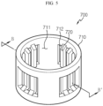
- a rubber ring 600 and a bushing member 700 may be provided to prevent damage to the ceramic insulating heat dissipation member 330.
- the rubber ring 600 is interposed between the fastening member 500 or the bolt and the insulating heat dissipation member 330.
- the rubber ring 600 protects the insulating heat dissipation member 330 from vertical impacts or vibrations.
- the bushing member 700 protects the insulating heat dissipation member 330 from horizontal impacts or vibrations.
- the bushing member 700 may include a body 710 and protrusions 720.
- the body 710 has a hollow 711, and the bolt is inserted into the hollow 711 of the body 710.
- the body 710 may have a plurality of through-hole shaped cut portions 712 between the protrusions 720.
- the protrusions 720 are formed in the body 710, and protrude from the body 710 toward the bolt and come into contact with the bolt as shown in FIG. 7 . As described above, it is possible to mitigate horizontal impacts or vibrations by the contact between the protrusions 720 and the bolt.
- a buffer space 800 may be formed between the bushing member 700 and the fastening member 500 or the bolt.
- the buffer space 800 prevents the direct transfer of vibration generated from the bolt to the insulating heat dissipation member 330 to protect the insulating heat dissipation member 330.
- the body 710 has the protrusions 720, and as opposed to FIGS. 5 and 6 , does not have the plurality of cut portions 712.0
- the battery pack 10 includes the first busbar member 310 and the second busbar member 320 to transfer electrical energy.
- heat generated during the transfer of electrical energy through any one busbar member moves the other busbar member through the insulating heat dissipation member 330 and into the outside atmosphere.
- the insulating heat dissipation member 330 may be made of a brittle ceramic material, and the rubber ring 600 and the bushing member 700 may be provided to prevent damage from vibration of the bolt.
- a vehicle may include the battery pack 10 described above.
- the battery pack 10 may be used in various types of machine or devices using electricity, and for example, may be disposed in an electric vehicle, in particular, the under floor of the electric vehicle.
- the electric vehicle may include an electric vehicle that drives using only electricity but also a hybrid vehicle using electrical energy together with other energy sources.
- the present disclosure relates to a battery pack and a vehicle comprising the same, and in particular, can be used in the industrial applications related to secondary batteries.
Abstract
Disclosed are a battery pack and a vehicle comprising the same. The battery pack according to an embodiment of the present disclosure includes a battery module including a plurality of battery cells; a case in which the battery module is received; and a busbar unit connected to the battery module, wherein the busbar unit is used for electrical connection and heat dissipation.
Description
- The present application claims the benefit of
Korean Patent Application No. 10-2021-0093113 filed on July 15, 2021 - The present disclosure relates to a battery pack and a vehicle comprising the same, and more particularly, to a battery pack including a busbar unit capable of heat dissipation and a vehicle comprising the same.
- With the technology development and growing demand for mobile devices, the demand for secondary batteries as an energy source is sharply increasing, and among secondary batteries, nickel-cadmium batteries or hydrogen ion batteries have been used, but recently, compared to nickel-based secondary batteries, lithium secondary batteries are being widely used since they have little or no memory effect so recharging can be done whenever it is convenient, the self-discharge rate is very low and the energy density is high.
- A lithium secondary battery usually uses a lithium-based oxide and a carbon material for a positive electrode active material and a negative electrode active material, respectively. The lithium secondary battery includes an electrode assembly including a positive electrode plate and a negative electrode plate coated with the positive electrode active material and the negative electrode active material, respectively, with a separator interposed between the positive electrode plate and the negative electrode plate, and a packaging or a battery case in which the electrode assembly is hermetically received together with an electrolyte solution.
- The lithium secondary battery includes positive and negative electrodes and the separator and the electrolyte interposed between them, and is classified into a Lithium Ion Battery (LIB) and a Polymer Lithium Ion Battery (PLIB) according to the types of the positive and negative electrode active materials. In general, the electrode of the lithium secondary battery may be formed by applying the positive or negative electrode active material to a current collector of an aluminum or copper sheet, mesh, film, foil and drying.
- A battery pack may include a busbar connected to a battery module to operate an object such as a vehicle, and another busbar connected to the battery module to charge the battery module.
- However, as higher current is used, a larger amount of heat is generated from the busbar, which increases the cross-sectional area of the busbar, resulting in increased weight and cost of the battery pack.
- The present disclosure is directed to providing a battery pack including a busbar unit capable of heat dissipation to reduce the cross-sectional area of the busbar and reduce the size and cost of the battery pack and a vehicle comprising the same.
- According to an aspect of the present disclosure, there is provided a battery pack including a battery module including a plurality of battery cells; a case in which the battery module is received; and a busbar unit connected to the battery module, wherein the busbar unit is used for electrical connection and heat dissipation.
- Additionally, the busbar unit may include a first busbar member to connect an object to the battery module to operate the object; a second busbar member to connect the battery module to a charging member for charging the battery module; and an insulating heat dissipation member to connect the first busbar member to the second busbar member, and used for electrical insulation and heat transfer.
- Additionally, the battery pack may further include a relay member coupled to the busbar unit; and a fastening member to fasten the busbar unit to the relay member, the first busbar member and the second busbar member may be disposed on the relay member, and the insulating heat dissipation member may be disposed above the first busbar member and the second busbar member.
- Additionally, the relay member may include a first relay member coupled to the first busbar member and a second relay member coupled to the second busbar member, the fastening member may include a first fastening member coupled to the first busbar member and a second fastening mmeber coupled to the second busbar member, the first busbar member and the first relay member may be fastened to a first end of the insulating heat dissipation member by the first fastening member, and the second busbar member and the second relay member may be fastened to a second end of the insulating heat dissipation member by the second fastening member.
- Additionally, the insulating heat dissipation member may be H-shaped.
- Additionally, the insulating heat dissipation member may be made of a ceramic material.
- Additionally, the fastening member may be a bolt, and a rubber ring may be interposed between the bolt and the insulating heat dissipation member.
- Additionally, the fastening member may be a bolt, and the battery pack may include a bushing member into which the bolt is inserted.
- Additionally, the bushing member may include a body having a hollow into which the bolt is inserted; and protrusions which protrude from the body toward the bolt and come into contact with the bolt.
- Additionally, the body may have a plurality of through-hole shaped cut portions between the protrusions.
- Additionally, a buffer space may be formed between the bushing member and the bolt.
- According to another aspect of the present disclosure, there is provided a vehicle including the battery pack.
- According to the embodiments of the present disclosure, the busbar unit is capable of heat dissipation, thereby reducing the cross-sectional area of the busbar and reducing the size and cost of the battery pack.
-
-
FIG. 1 is a plan view showing the inner parts of a battery pack according to an embodiment of the present disclosure. -
FIG. 2 is a perspective view of a busbar unit in a battery pack according to an embodiment of the present disclosure. -
FIG. 3 is a plan view of the busbar unit ofFIG. 2 . -
FIG. 4 is a cross-sectional view ofFIG. 3 taken along the line A-A'. -
FIG. 5 is a perspective view of a bushing member ofFIG. 4 . -
FIG. 6 is a cross-sectional view ofFIG. 5 taken along the line B-B'. -
FIG. 7 is an enlarged view of section X inFIG. 4 . -
FIG. 8 is a perspective view of another embodiment of the bushing member ofFIG. 5 . -
FIG. 9 is a cross-sectional view ofFIG. 8 taken along the line C-C'. - Hereinafter, exemplary embodiments of the present disclosure will be described in detail with reference to the accompanying drawings. Prior to the description, it should be understood that the terms or words used in the specification and the appended claims should not be construed as being limited to general and dictionary meanings, but rather interpreted based on the meanings and concepts corresponding to the technical aspects of the present disclosure on the basis of the principle that the inventor is allowed to define the terms appropriately for the best explanation. Therefore, the embodiments described herein and illustrations shown in the drawings are just an exemplary embodiment of the present disclosure, but not intended to fully describe the technical aspects of the present disclosure, so it should be understood that a variety of other equivalents and modifications could have been made thereto at the time that the application was filed.
- The size of each element or particular parts of the element in the drawings is exaggerated or omitted or schematically illustrated for convenience and clarity of description. Accordingly, the size of each element does not necessarily reflect the actual size. When it is determined that a certain detailed description of relevant known functions or components may unnecessarily obscure the subject matter of the present disclosure, the description is omitted.
- The term 'couple' or 'connect' as used herein includes not only a direct coupling or connection of an element to another element but also an indirect coupling or connection of an element to another element through a connection member.
-
FIG. 1 is a plan view showing the inner parts of a battery pack according to an embodiment of the present disclosure,FIG. 2 is a perspective view of a busbar unit in the battery pack according to an embodiment of the present disclosure,FIG. 3 is a plan view of the busbar unit ofFIG. 2 ,FIG. 4 is a cross-sectional view ofFIG. 3 taken along the line A-A',FIG. 5 is a perspective view of a bushing member ofFIG. 4 ,FIG. 6 is a cross-sectional view ofFIG. 5 taken along the line B-B',FIG. 7 is an enlarged view of section X inFIG. 4 ,FIG. 8 is a perspective view of another embodiment of the bushing member ofFIG. 5 , andFIG. 9 is a cross-sectional view ofFIG. 8 taken along the line C-C'. - Referring to the drawings, the
battery pack 10 according to an embodiment of the present disclosure includes abattery module 100, acase 200 and thebusbar unit 300. - Referring to
FIG. 1 , thebattery module 100 includes a plurality ofbattery cells 110. Thebattery cell 110 may have a stack of unit cells, each unit cell including a positive electrode plate, a separator and a negative electrode plate arranged in that order, or a stack of bi-cells, each bi-cell including a positive electrode plate, a separator, a negative electrode plate, a separator, a positive electrode plate, a separator and a negative electrode plate arranged in that order, according to the battery capacity. - Additionally, the
battery cells 110 may include electrode leads. The electrode leads may be terminals that are exposed to the outside and connected to an external device, and may be made of a conductive material. - The electrode leads may include positive and negative electrode leads. The positive and negative electrode leads may be disposed in the same direction or opposite directions along the lengthwise direction of the
battery cells 110. - The
battery module 100 may include a plurality of cartridges in which thebattery cells 110 are received. Each cartridge may be made by plastic injection molding, and the plurality of cartridges having a receiving portion for receiving thebattery cells 110 may be stacked. - A cartridge assembly including the stack of cartridges may include a connector element or a terminal element.
- The connector element may include, for example, various types of electrical connection components or connection members to connect to a Battery Management System (BMS) (not shown) that provides data associated with the voltage or temperature of the
battery cells 110. - Additionally, the terminal element may be a main terminal connected to the
battery cells 110 and may include a positive terminal and a negative terminal. The terminal element may include a terminal bolt to electrically connect to an external device. - The
case 200 accommodates at least onebattery module 100. The plurality ofbattery modules 100 may be stacked in thecase 200 or may be arranged in various patterns in thecase 200. - The
case 200 accommodates the plurality ofbattery modules 100 to protect them. That is, thecase 200 covers all thebattery modules 100 to protect them from external vibrations or impacts. - The
case 200 may have a shape that conforms to the shape of thebattery module 100. For example, when the stackedbattery modules 100 have a hexahedral shape as a whole, thecase 200 may have a hexahedral shape that conforms to it. However, the present disclosure is not limited thereto. - For example, the
case 200 may be made by bending a metal plate, and thus thecase 200 may be integrally formed. Here, when thecase 200 is integrally formed, the coupling process is simple and straightforward. - Alternatively, the
split type case 200 may be coupled using a variety of methods, for example, weld, rivet, bolt, pin, bracket or moment joining. Additionally, thebattery pack 10 may include different types of devices for controlling the charge/discharge of thebattery module 100, for example, a BMS, a current sensor and a fuse. - The
busbar unit 300 is connected to thebattery module 100. Thebusbar unit 300 is electrically connected to thebattery module 100 and is capable of heat dissipation. - Referring to
FIGS. 2 and3 , thebusbar unit 300 may include afirst busbar member 310, asecond busbar member 320 and an insulatingheat dissipation member 330. - The
first busbar member 310 is configured to connect anobject 910 to thebattery module 100 to operate the object 910 (seeFIG. 1 ). Thefirst busbar member 310 may be connected to theobject 910 through aconnection terminal 210. Here, various types ofobjects 910 may be connected to thebattery module 100. - For example, the
object 910 may be an electric vehicle, and when theobject 910 is an electric vehicle, thefirst busbar member 310 is configured to move electrical energy used to operate the electric vehicle from thebattery module 100 to the electric vehicle. - However, the
object 910 is not limited to the electric vehicle, and for convenience of description, the following description is made by taking the electric vehicle as an example of theobject 910. - The
second busbar member 320 is configured to connect thebattery module 100 to a charging member 920 (seeFIG. 1 ) for charging thebattery module 100. Thesecond busbar member 320 may be connected to the chargingmember 920 through a chargingterminal 220. - That is, electrical energy for operating the
object 910 or the electric vehicle moves from thebattery module 100 to the electric vehicle through thefirst busbar member 310, and when thebattery module 100 is charged after the end of the operation of the electric vehicle, electrical energy for charging moves from the chargingmember 920 to thebattery module 100 through thesecond busbar member 320. - The insulating
heat dissipation member 330 is used for electrical insulation and heat transfer, and connects thefirst busbar member 310 to thesecond busbar member 320. To this end, the insulatingheat dissipation member 330 may be made of a ceramic material. - However, the material of the insulating
heat dissipation member 330 is not limited to the ceramic material, and the material of the insulatingheat dissipation member 330 may include various types of materials having the insulation and heat dissipation properties. - As described above, during the operation of the electric vehicle, electrical energy moves from the
battery module 100 to the electric vehicle through thefirst busbar member 310, so heat is generated from thefirst busbar member 310. In particular, since the electric vehicle uses high current, there is an increase in the amount of heat generated. - Here, since the
second busbar member 320 is not used while electrical energy is moving through thefirst busbar member 310, heat generated from thefirst busbar member 310 may move to thesecond busbar member 320 through the insulatingheat dissipation member 330 and into the outside atmosphere. - In this instance, since the insulating
heat dissipation member 330 is electrically insulated, heat is transferred from thefirst busbar member 310 to thesecond busbar member 320, but electricity does not move. Hereinafter, when heat is transferred from thesecond busbar member 320 to thefirst busbar member 310, likewise, electricity does not move. - Additionally, during the charging of the electric vehicle, electrical energy moves from the charging
member 920 to thebattery module 100 through thesecond busbar member 320, and heat is generated from thesecond busbar member 320. - Here, since the
first busbar member 310 is not used while electrical energy moves through thesecond busbar member 320, heat generated from thesecond busbar member 320 may move to thefirst busbar member 310 through the insulatingheat dissipation member 330 and into the outside atmosphere. - That is, when any one of the
first busbar member 310 and thesecond busbar member 320 is used, the other is not used, and heat generated from the busbar member being used may move to the busbar member not in use through the insulatingheat dissipation member 330 and into the outside atmosphere. - Referring to
FIGS. 2 and4 , arelay member 400 may be coupled to thebusbar unit 300. Thefirst busbar member 310 and thesecond busbar member 320 may be disposed on therelay member 400. Additionally, the insulatingheat dissipation member 330 may be disposed above thefirst busbar member 310 and thesecond busbar member 320. - The
relay member 400 may include afirst relay member 410 coupled to thefirst busbar member 310 and asecond relay member 420 coupled to thesecond busbar member 320. - A
fastening member 500 fastens thebusbar unit 300 to therelay member 400. Thefastening member 500 may come in various types, and for example, may include a bolt and nut. The nut may be coupled to therelay member 400, or the nut may be integrally formed in therelay member 400 itself. - However, the
fastening member 500 is not limited to the bolt and nut, and thefastening member 500 may include a variety of known structures. However, for convenience of description, the following description is made by taking the bolt and the nut integrally formed in therelay member 400 as an example of thefastening member 500. - The
fastening member 500 may include afirst fastening member 510 coupled to thefirst busbar member 310 and asecond fastening member 520 coupled to thesecond busbar member 320. - The
first busbar member 310 and thefirst relay member 410 may be fastened to afirst end 331 of the insulatingheat dissipation member 330 by thefirst fastening member 510. Additionally, thesecond busbar member 320 and thesecond relay member 420 may be fastened to asecond end 332 of the insulatingheat dissipation member 330 by thesecond fastening member 520. - Here, referring to
FIGS. 2 and3 , the insulatingheat dissipation member 330 may be H-shaped. However, the shape of the insulatingheat dissipation member 330 is not limited to the H shape. - As described above, the insulating
heat dissipation member 330 may be made of a ceramic material for good electrical insulation and heat transfer. However, the ceramic material may be vulnerable to damage due to its brittleness. - Here, a
rubber ring 600 and abushing member 700 may be provided to prevent damage to the ceramic insulatingheat dissipation member 330. - Referring to
FIG. 4 , therubber ring 600 is interposed between the fasteningmember 500 or the bolt and the insulatingheat dissipation member 330. Therubber ring 600 protects the insulatingheat dissipation member 330 from vertical impacts or vibrations. - Additionally, the
fastening member 500 or the bolt is inserted into thebushing member 700. Thebushing member 700 protects the insulatingheat dissipation member 330 from horizontal impacts or vibrations. - Referring to
FIGS. 5 to 7 , thebushing member 700 may include abody 710 andprotrusions 720. - The
body 710 has a hollow 711, and the bolt is inserted into the hollow 711 of thebody 710. Thebody 710 may have a plurality of through-hole shaped cutportions 712 between theprotrusions 720. - The
protrusions 720 are formed in thebody 710, and protrude from thebody 710 toward the bolt and come into contact with the bolt as shown inFIG. 7 . As described above, it is possible to mitigate horizontal impacts or vibrations by the contact between theprotrusions 720 and the bolt. - Referring to
FIG. 7 , abuffer space 800 may be formed between thebushing member 700 and thefastening member 500 or the bolt. Here, thebuffer space 800 prevents the direct transfer of vibration generated from the bolt to the insulatingheat dissipation member 330 to protect the insulatingheat dissipation member 330. - Referring to
FIGS. 8 and9 according to another embodiment ofFIGS. 5 and6 , thebody 710 has theprotrusions 720, and as opposed toFIGS. 5 and6 , does not have the plurality of cut portions 712.0 - The foregoing description replaces the common description to the embodiment of
FIGS. 5 and6 and the embodiment ofFIGS. 8 and9 . - Hereinafter, the operation and effect of the
battery pack 10 according to an embodiment of the present disclosure will be described with reference to the accompanying drawings. - The
battery pack 10 includes thefirst busbar member 310 and thesecond busbar member 320 to transfer electrical energy. Here, heat generated during the transfer of electrical energy through any one busbar member moves the other busbar member through the insulatingheat dissipation member 330 and into the outside atmosphere. - Additionally, the insulating
heat dissipation member 330 may be made of a brittle ceramic material, and therubber ring 600 and thebushing member 700 may be provided to prevent damage from vibration of the bolt. - Accordingly, it is possible to reduce the cross-sectional area of the busbar through heat dissipation structure, and reduce the size and cost of the
battery pack 10. - A vehicle (not shown) according to an embodiment of the present disclosure may include the
battery pack 10 described above. Thebattery pack 10 may be used in various types of machine or devices using electricity, and for example, may be disposed in an electric vehicle, in particular, the under floor of the electric vehicle. Here, the electric vehicle may include an electric vehicle that drives using only electricity but also a hybrid vehicle using electrical energy together with other energy sources. - While the present disclosure has been hereinabove described with regard to a limited number of embodiments and drawings, the present disclosure is not limited thereto and it is obvious to those skilled in the art that various modifications and changes may be made in the technical aspects of the present disclosure and the scope of the appended claims and equivalents thereof.
- The present disclosure relates to a battery pack and a vehicle comprising the same, and in particular, can be used in the industrial applications related to secondary batteries.
Claims (12)
- A battery pack, comprising:a battery module including a plurality of battery cells;a case in which the battery module is received; anda busbar unit connected to the battery module,wherein the busbar unit is used for electrical connection and heat dissipation.
- The battery pack according to claim 1, wherein the busbar unit includes:a first busbar member to connect an object to the battery module to operate the obj ect;a second busbar member to connect the battery module to a charging member for charging the battery module; andan insulating heat dissipation member to connect the first busbar member to the second busbar member, and used for electrical insulation and heat transfer.
- The battery pack according to claim 2, further comprising:a relay member coupled to the busbar unit; anda fastening member to fasten the busbar unit to the relay member,wherein the first busbar member and the second busbar member is disposed on the relay member, andwherein the insulating heat dissipation member is disposed above the first busbar member and the second busbar member.
- The battery pack according to claim 3, wherein the relay member includes a first relay member coupled to the first busbar member and a second relay member coupled to the second busbar member,wherein the fastening member includes a first fastening member coupled to the first busbar member and a second fastening mmeber coupled to the second busbar member,wherein the first busbar member and the first relay member are fastened to a first end of the insulating heat dissipation member by the first fastening member, andwherein the second busbar member and the second relay member are fastened to a second end of the insulating heat dissipation member by the second fastening member.
- The battery pack according to claim 4, wherein the insulating heat dissipation member is H-shaped.
- The battery pack according to claim 3, wherein the insulating heat dissipation member is made of a ceramic material.
- The battery pack according to claim 6, wherein the fastening member is a bolt, and
wherein a rubber ring is interposed between the bolt and the insulating heat dissipation member. - The battery pack according to claim 6, wherein the fastening member is a bolt, and
wherein the battery pack includes a bushing member into which the bolt is inserted. - The battery pack according to claim 8, wherein the bushing member includes:a body having a hollow into which the bolt is inserted; andprotrusions which protrude from the body toward the bolt and come into contact with the bolt.
- The battery pack according to claim 9, wherein the body has a plurality of through-hole shaped cut portions between the protrusions.
- The battery pack according to claim 9, wherein a buffer space is formed between the bushing member and the bolt.
- A vehicle comprising the battery pack according to any one of claims 1 to 11.
Applications Claiming Priority (2)
| Application Number | Priority Date | Filing Date | Title |
|---|---|---|---|
| KR1020210093113A KR20230012355A (en) | 2021-07-15 | 2021-07-15 | Battery pack and vehicle including the same |
| PCT/KR2022/010070 WO2023287143A1 (en) | 2021-07-15 | 2022-07-11 | Battery pack and vehicle including same |
Publications (1)
| Publication Number | Publication Date |
|---|---|
| EP4283775A1 true EP4283775A1 (en) | 2023-11-29 |
Family
ID=84920154
Family Applications (1)
| Application Number | Title | Priority Date | Filing Date |
|---|---|---|---|
| EP22842405.7A Pending EP4283775A1 (en) | 2021-07-15 | 2022-07-11 | Battery pack and vehicle including same |
Country Status (5)
| Country | Link |
|---|---|
| EP (1) | EP4283775A1 (en) |
| JP (1) | JP2024510563A (en) |
| KR (1) | KR20230012355A (en) |
| CN (1) | CN117044029A (en) |
| WO (1) | WO2023287143A1 (en) |
Family Cites Families (7)
| Publication number | Priority date | Publication date | Assignee | Title |
|---|---|---|---|---|
| JP2006158120A (en) | 2004-11-30 | 2006-06-15 | Yazaki Corp | Electric connection box and its heat dissipation method |
| US8288031B1 (en) * | 2011-03-28 | 2012-10-16 | Lg Chem, Ltd. | Battery disconnect unit and method of assembling the battery disconnect unit |
| KR20180013460A (en) * | 2016-07-29 | 2018-02-07 | 박동식 | Battery apparatus |
| JP6988399B2 (en) * | 2016-12-05 | 2022-01-05 | トヨタ自動車株式会社 | In-vehicle battery relay connection structure |
| KR102204302B1 (en) * | 2018-09-13 | 2021-01-15 | 주식회사 엘지화학 | Battery module, battery pack comprising the battery module and vehicle comprising the battery pack |
| KR20210066528A (en) * | 2019-11-28 | 2021-06-07 | 주식회사 엘지에너지솔루션 | Battery module and battery pack including the same |
| KR20210093113A (en) | 2020-01-17 | 2021-07-27 | 주식회사 파인씨엔이 | F.r.p flange pipe |
-
2021
- 2021-07-15 KR KR1020210093113A patent/KR20230012355A/en unknown
-
2022
- 2022-07-11 WO PCT/KR2022/010070 patent/WO2023287143A1/en active Application Filing
- 2022-07-11 JP JP2023553100A patent/JP2024510563A/en active Pending
- 2022-07-11 CN CN202280023325.4A patent/CN117044029A/en active Pending
- 2022-07-11 EP EP22842405.7A patent/EP4283775A1/en active Pending
Also Published As
| Publication number | Publication date |
|---|---|
| JP2024510563A (en) | 2024-03-08 |
| CN117044029A (en) | 2023-11-10 |
| WO2023287143A1 (en) | 2023-01-19 |
| KR20230012355A (en) | 2023-01-26 |
Similar Documents
| Publication | Publication Date | Title |
|---|---|---|
| CN110603662B (en) | Bus bar assembly for bonding electrode leads and battery module including the same | |
| EP3614453A1 (en) | Battery module and battery pack including same | |
| CN108463901B (en) | Battery module and battery pack including the same | |
| US11031650B2 (en) | Battery module and battery pack comprising same | |
| EP3582286A1 (en) | Battery cell frame and battery module comprising same | |
| CN110050361B (en) | Battery module, battery pack including the same, and method for manufacturing the same | |
| EP3297061A1 (en) | Battery pack | |
| US20200028216A1 (en) | Battery Module and Battery Module Manufacturing Method | |
| KR20190007745A (en) | Battery pack | |
| EP4012823A1 (en) | Battery module, and battery rack and power storage device, each comprising same battery module | |
| US20230031678A1 (en) | Battery Module, and Battery Pack and Vehicle Comprising Battery Module | |
| EP4283775A1 (en) | Battery pack and vehicle including same | |
| US20240136613A1 (en) | Battery pack and vehicle comprising the same | |
| CN115699428A (en) | Battery pack and vehicle including the same | |
| KR20210060239A (en) | Battery module, battery pack and vehicle comprising the same | |
| EP4075573A1 (en) | Battery module, and battery pack and vehicle comprising same | |
| KR20200099392A (en) | The Secondary Battery And The Battery Module | |
| US20230420770A1 (en) | Battery Module, and Battery Pack and Vehicle Including the Same | |
| EP4138190A1 (en) | Battery module, and battery pack and automobile including same | |
| EP4087012A1 (en) | Battery module, and battery pack and vehicle which comprise same | |
| CN212874708U (en) | Secondary battery, battery module, battery pack, and device | |
| EP4336639A1 (en) | Battery module, and battery pack and vehicle comprising same | |
| JP7462764B2 (en) | Secondary battery and battery module | |
| CN117480671A (en) | Battery module, battery pack including the same, and vehicle | |
| CN117712509A (en) | Secondary battery cell |
Legal Events
| Date | Code | Title | Description |
|---|---|---|---|
| STAA | Information on the status of an ep patent application or granted ep patent |
Free format text: STATUS: THE INTERNATIONAL PUBLICATION HAS BEEN MADE |
|
| PUAI | Public reference made under article 153(3) epc to a published international application that has entered the european phase |
Free format text: ORIGINAL CODE: 0009012 |
|
| STAA | Information on the status of an ep patent application or granted ep patent |
Free format text: STATUS: REQUEST FOR EXAMINATION WAS MADE |
|
| 17P | Request for examination filed |
Effective date: 20230823 |
|
| AK | Designated contracting states |
Kind code of ref document: A1 Designated state(s): AL AT BE BG CH CY CZ DE DK EE ES FI FR GB GR HR HU IE IS IT LI LT LU LV MC MK MT NL NO PL PT RO RS SE SI SK SM TR |