EP3581428B1 - Kurzschlussbremsung eines llm - Google Patents
Kurzschlussbremsung eines llm Download PDFInfo
- Publication number
- EP3581428B1 EP3581428B1 EP18177762.4A EP18177762A EP3581428B1 EP 3581428 B1 EP3581428 B1 EP 3581428B1 EP 18177762 A EP18177762 A EP 18177762A EP 3581428 B1 EP3581428 B1 EP 3581428B1
- Authority
- EP
- European Patent Office
- Prior art keywords
- short
- circuit
- drive coils
- circuit current
- transport unit
- Prior art date
- Legal status (The legal status is an assumption and is not a legal conclusion. Google has not performed a legal analysis and makes no representation as to the accuracy of the status listed.)
- Active
Links
Images


Classifications
-
- H—ELECTRICITY
- H02—GENERATION; CONVERSION OR DISTRIBUTION OF ELECTRIC POWER
- H02P—CONTROL OR REGULATION OF ELECTRIC MOTORS, ELECTRIC GENERATORS OR DYNAMO-ELECTRIC CONVERTERS; CONTROLLING TRANSFORMERS, REACTORS OR CHOKE COILS
- H02P3/00—Arrangements for stopping or slowing electric motors, generators, or dynamo-electric converters
- H02P3/06—Arrangements for stopping or slowing electric motors, generators, or dynamo-electric converters for stopping or slowing an individual dynamo-electric motor or dynamo-electric converter
-
- H—ELECTRICITY
- H02—GENERATION; CONVERSION OR DISTRIBUTION OF ELECTRIC POWER
- H02P—CONTROL OR REGULATION OF ELECTRIC MOTORS, ELECTRIC GENERATORS OR DYNAMO-ELECTRIC CONVERTERS; CONTROLLING TRANSFORMERS, REACTORS OR CHOKE COILS
- H02P25/00—Arrangements or methods for the control of AC motors characterised by the kind of AC motor or by structural details
- H02P25/02—Arrangements or methods for the control of AC motors characterised by the kind of AC motor or by structural details characterised by the kind of motor
- H02P25/06—Linear motors
-
- B—PERFORMING OPERATIONS; TRANSPORTING
- B60—VEHICLES IN GENERAL
- B60L—PROPULSION OF ELECTRICALLY-PROPELLED VEHICLES; SUPPLYING ELECTRIC POWER FOR AUXILIARY EQUIPMENT OF ELECTRICALLY-PROPELLED VEHICLES; ELECTRODYNAMIC BRAKE SYSTEMS FOR VEHICLES IN GENERAL; MAGNETIC SUSPENSION OR LEVITATION FOR VEHICLES; MONITORING OPERATING VARIABLES OF ELECTRICALLY-PROPELLED VEHICLES; ELECTRIC SAFETY DEVICES FOR ELECTRICALLY-PROPELLED VEHICLES
- B60L13/00—Electric propulsion for monorail vehicles, suspension vehicles or rack railways; Magnetic suspension or levitation for vehicles
- B60L13/10—Combination of electric propulsion and magnetic suspension or levitation
-
- B—PERFORMING OPERATIONS; TRANSPORTING
- B60—VEHICLES IN GENERAL
- B60L—PROPULSION OF ELECTRICALLY-PROPELLED VEHICLES; SUPPLYING ELECTRIC POWER FOR AUXILIARY EQUIPMENT OF ELECTRICALLY-PROPELLED VEHICLES; ELECTRODYNAMIC BRAKE SYSTEMS FOR VEHICLES IN GENERAL; MAGNETIC SUSPENSION OR LEVITATION FOR VEHICLES; MONITORING OPERATING VARIABLES OF ELECTRICALLY-PROPELLED VEHICLES; ELECTRIC SAFETY DEVICES FOR ELECTRICALLY-PROPELLED VEHICLES
- B60L7/00—Electrodynamic brake systems for vehicles in general
- B60L7/003—Dynamic electric braking by short circuiting the motor
-
- B—PERFORMING OPERATIONS; TRANSPORTING
- B60—VEHICLES IN GENERAL
- B60L—PROPULSION OF ELECTRICALLY-PROPELLED VEHICLES; SUPPLYING ELECTRIC POWER FOR AUXILIARY EQUIPMENT OF ELECTRICALLY-PROPELLED VEHICLES; ELECTRODYNAMIC BRAKE SYSTEMS FOR VEHICLES IN GENERAL; MAGNETIC SUSPENSION OR LEVITATION FOR VEHICLES; MONITORING OPERATING VARIABLES OF ELECTRICALLY-PROPELLED VEHICLES; ELECTRIC SAFETY DEVICES FOR ELECTRICALLY-PROPELLED VEHICLES
- B60L7/00—Electrodynamic brake systems for vehicles in general
- B60L7/02—Dynamic electric resistor braking
- B60L7/08—Controlling the braking effect
-
- H—ELECTRICITY
- H02—GENERATION; CONVERSION OR DISTRIBUTION OF ELECTRIC POWER
- H02K—DYNAMO-ELECTRIC MACHINES
- H02K11/00—Structural association of dynamo-electric machines with electric components or with devices for shielding, monitoring or protection
- H02K11/20—Structural association of dynamo-electric machines with electric components or with devices for shielding, monitoring or protection for measuring, monitoring, testing, protecting or switching
- H02K11/21—Devices for sensing speed or position, or actuated thereby
-
- H—ELECTRICITY
- H02—GENERATION; CONVERSION OR DISTRIBUTION OF ELECTRIC POWER
- H02K—DYNAMO-ELECTRIC MACHINES
- H02K11/00—Structural association of dynamo-electric machines with electric components or with devices for shielding, monitoring or protection
- H02K11/30—Structural association with control circuits or drive circuits
- H02K11/33—Drive circuits, e.g. power electronics
-
- H—ELECTRICITY
- H02—GENERATION; CONVERSION OR DISTRIBUTION OF ELECTRIC POWER
- H02K—DYNAMO-ELECTRIC MACHINES
- H02K41/00—Propulsion systems in which a rigid body is moved along a path due to dynamo-electric interaction between the body and a magnetic field travelling along the path
- H02K41/02—Linear motors; Sectional motors
-
- H—ELECTRICITY
- H02—GENERATION; CONVERSION OR DISTRIBUTION OF ELECTRIC POWER
- H02K—DYNAMO-ELECTRIC MACHINES
- H02K41/00—Propulsion systems in which a rigid body is moved along a path due to dynamo-electric interaction between the body and a magnetic field travelling along the path
- H02K41/02—Linear motors; Sectional motors
- H02K41/03—Synchronous motors; Motors moving step by step; Reluctance motors
- H02K41/031—Synchronous motors; Motors moving step by step; Reluctance motors of the permanent magnet type
-
- H—ELECTRICITY
- H02—GENERATION; CONVERSION OR DISTRIBUTION OF ELECTRIC POWER
- H02P—CONTROL OR REGULATION OF ELECTRIC MOTORS, ELECTRIC GENERATORS OR DYNAMO-ELECTRIC CONVERTERS; CONTROLLING TRANSFORMERS, REACTORS OR CHOKE COILS
- H02P3/00—Arrangements for stopping or slowing electric motors, generators, or dynamo-electric converters
- H02P3/06—Arrangements for stopping or slowing electric motors, generators, or dynamo-electric converters for stopping or slowing an individual dynamo-electric motor or dynamo-electric converter
- H02P3/08—Arrangements for stopping or slowing electric motors, generators, or dynamo-electric converters for stopping or slowing an individual dynamo-electric motor or dynamo-electric converter for stopping or slowing a DC motor
- H02P3/12—Arrangements for stopping or slowing electric motors, generators, or dynamo-electric converters for stopping or slowing an individual dynamo-electric motor or dynamo-electric converter for stopping or slowing a DC motor by short-circuit or resistive braking
-
- H—ELECTRICITY
- H02—GENERATION; CONVERSION OR DISTRIBUTION OF ELECTRIC POWER
- H02P—CONTROL OR REGULATION OF ELECTRIC MOTORS, ELECTRIC GENERATORS OR DYNAMO-ELECTRIC CONVERTERS; CONTROLLING TRANSFORMERS, REACTORS OR CHOKE COILS
- H02P3/00—Arrangements for stopping or slowing electric motors, generators, or dynamo-electric converters
- H02P3/06—Arrangements for stopping or slowing electric motors, generators, or dynamo-electric converters for stopping or slowing an individual dynamo-electric motor or dynamo-electric converter
- H02P3/18—Arrangements for stopping or slowing electric motors, generators, or dynamo-electric converters for stopping or slowing an individual dynamo-electric motor or dynamo-electric converter for stopping or slowing an AC motor
- H02P3/22—Arrangements for stopping or slowing electric motors, generators, or dynamo-electric converters for stopping or slowing an individual dynamo-electric motor or dynamo-electric converter for stopping or slowing an AC motor by short-circuit or resistive braking
-
- H—ELECTRICITY
- H02—GENERATION; CONVERSION OR DISTRIBUTION OF ELECTRIC POWER
- H02P—CONTROL OR REGULATION OF ELECTRIC MOTORS, ELECTRIC GENERATORS OR DYNAMO-ELECTRIC CONVERTERS; CONTROLLING TRANSFORMERS, REACTORS OR CHOKE COILS
- H02P7/00—Arrangements for regulating or controlling the speed or torque of electric DC motors
- H02P7/02—Arrangements for regulating or controlling the speed or torque of electric DC motors the DC motors being of the linear type
-
- B—PERFORMING OPERATIONS; TRANSPORTING
- B65—CONVEYING; PACKING; STORING; HANDLING THIN OR FILAMENTARY MATERIAL
- B65G—TRANSPORT OR STORAGE DEVICES, e.g. CONVEYORS FOR LOADING OR TIPPING, SHOP CONVEYOR SYSTEMS OR PNEUMATIC TUBE CONVEYORS
- B65G54/00—Non-mechanical conveyors not otherwise provided for
- B65G54/02—Non-mechanical conveyors not otherwise provided for electrostatic, electric, or magnetic
Definitions
- the present invention relates to a method for controlling a plurality of drive coils of a long-stator linear motor, the drive coils being energized in normal operation in such a way that a magnetic field coupled to a transport unit is moved along a direction of movement in order to move the transport unit along the direction of movement, with a braking process the transport unit is switched to a regulated short-circuit mode, in which at least some of the drive coils are operated in a short-circuit for at least a first period of time.
- the present invention also relates to a long-stator linear motor with a plurality of drive coils and at least one transport unit, with an LLM controller controlled by a coil regulator being provided, which is designed to energize the drive coils in such a way that a magnetic field coupled to the transport unit is moved along a direction of movement to move the transport unit along the direction of movement.
- LLM long-stator linear motors
- rotary-to-linear transmission units such as rotary motors on a conveyor belt.
- Long stator linear motors are characterized by better and more flexible utilization over the entire working range. In this way, the speed and acceleration ranges from zero to the maximum can be used.
- individual regulation or control of the movable transport units shuttles
- improved energy utilization the reduction of maintenance costs due to the lower number of wearing parts
- simple replacement of the transport units efficient monitoring and simpler error detection
- optimization of the current consumed List elimination of power gaps as advantages.
- a stator of a long stator linear motor consists of a multiplicity of drive coils arranged next to one another in the direction of movement of the transport units, which together form the stator of the long stator linear motor.
- These drive coils are controlled individually or in groups, and it is often also desirable or necessary to change the polarity, ie the direction of current, of the drive coils during operation of the long-stator linear motor.
- a moving magnetic field is generated, which interacts with excitation magnets (usually permanent magnets) on a transport unit of the LLM in order to generate a propulsive force on the transport unit and thus to move the transport unit along the stator.
- an operating voltage between a first operating potential and a second operating potential is generally made available.
- Such long-stator linear motors are sufficiently known in various configurations, for example from the WO 2013/143783 A1 , the US 6,876,107 B2 , the US 2013/0074724 A1 or the WO 2004/103792 A1 , to name just a few.
- the AT 518 721 A1 discloses the use of half bridges instead of full bridges, a center point of the half bridges being connected to a first terminal of drive coils.
- the second connections of the drive coils are connected to a control point and an actual potential at the control point is regulated to a predetermined potential by a control unit.
- a positive and a negative coil voltage can be applied to the drive coils.
- the EP 0294 541 A1 describes a linear motor which has short-circuit braking, ie a braking process by short-circuiting coils.
- the EP 0 289 686 A2 describes a short-circuiting of coils, but no associated braking process.
- the DE 22 35 705 A1 discloses a transport unit which has short-circuit braking.
- This object is achieved according to the invention in that in the regulated short-circuit mode the at least one part of the drive coils is operated at least for a second period of time in an idle state.
- the object is also achieved by a short-circuit controller which is designed when the transport unit brakes at least a part of the drive coils short-circuit at least over a first period of time and operate in an idle state at least over a second period of time.
- the relevant drive coils are usually switched to a currentless state (which basically corresponds to idling) in order not to actively move the transport unit any further.
- the transport unit moves along the stator of the long-stator linear motor to a standstill with little delay (due to the desired low-friction storage or guidance of the transport units on the transport route) without suitable actions, which is undesirable because the transport units usually come to a standstill very quickly should be brought.
- a moving magnetic field is generated by the excitation magnets themselves. This magnetic field moves with the transport unit along the stator and thus also has the speed of the transport unit.
- This magnetic field also interacts with the drive coils of the stator, which would have no effect if the drive coils were open.
- the drive coils which are magnetically coupled to the transport unit, induce a coil short-circuit current via an electro-magnetic force (EMF) when the terminals are short-circuited.
- EMF electro-magnetic force
- this coil short-circuit current counteracts the magnetic field caused by the transport unit, whereby the transport unit is braked relatively quickly.
- the short circuit of the at least some of the drive coils is preferably maintained during the entire braking process, ie until the transport unit comes to a standstill.
- the transport unit can be braked at least to an uncritical speed from which the transport unit can then, for example, "roll out".
- the short-circuit current (as the sum of the respective flowing coil short-circuit currents) can be regulated in such a way that a larger current component in the direction of force (i.e. in a Cartesian field-oriented dq coordinate system in the q direction) is achieved. This increases the proportion of the short-circuit current that counteracts the field direction serving the propulsion movement, which results in a greater braking effect than in the case of a permanent short-circuit and with which the transport unit comes to a standstill even more quickly.
- a total short-circuit current flowing through the drive coils is determined and a setpoint short-circuit current with a maximum short-circuit current component icq that generates propulsive force is determined by means of a predetermined relationship.
- a short-circuit phase in which the short-circuit current is less than the target short-circuit current, at least some of the drive coils can be operated in a short-circuit.
- an idle phase in which the short-circuit current reaches or exceeds the target short-circuit current, the at least some of the drive coils can be operated in no-load mode.
- the short-circuit current in a short-circuit phase in which the short-circuit current is less than the target short-circuit current multiplied by a factor, at least some of the drive coils can be operated in a short-circuit.
- the at least some of the drive coils are operated alternately in short-circuit and idle.
- the at least some of the drive coils are operated in no-load operation.
- the at least some of the drive coils can be operated alternately over a short-circuit interval in short-circuit and over an idle interval in no-load, the duration of the short-circuit interval being determined by the duration of the idle interval and advantageously calculated using a third-order polynomial with an error deviation becomes.
- a factor of 0.85 can also be selected, which has a particularly good braking effect, as has also been confirmed in practice.
- the drive coils that are magnetically coupled to the transport unit can be determined by means of a position sensor. This can be advantageous if position sensors are already provided on the long stator linear motor anyway.
- the drive coils magnetically coupled to the transport unit can, however, also be recognized via a coil short-circuit current induced in the respective drive coil.
- This induced coil short-circuit current suggests a magnetic coupling with a transport unit.
- further drive coils can also be switched to the controlled short-circuit mode, for example a certain number of drive coils located in front of the transport unit in the direction of movement, etc.
- the duration of the braking process depends on the mass of the transport unit, as well as on additional masses bound to the transport unit (transported goods, workpiece, ...) and / or the speed of the transport unit.
- the energy that is released during the braking process is mainly converted into heat in the winding resistances (copper losses) and in the iron (mainly eddy current losses).
- a short circuit can mean different switch positions for different configurations of an LLM control unit. Does the LLM control unit have full bridges, as in the US 2006/0220623 A1 , with four switches per drive coil on, a full short circuit can be switched during the controlled short circuit in the short circuit phase or the short circuit interval. However, if the LLM control unit has half bridges, comprising an upper and a lower switch per drive coil (see AT 518 721 A1 ), the short circuit is modulated in the short circuit phase or the short circuit interval. This means that the upper switch of the half bridge is switched through alternately with the lower switch of the half bridge, preferably in a ratio of 50/50. However, the upper switch and the lower switch must not be switched through at the same time.
- Fig. 1 represents a simple example of a long stator linear motor 2.
- the long stator linear motor 2 is designed as a closed transport path 20.
- On the transport path 20 a plurality m of drive coils Sm are arranged one behind the other in the direction of movement x of a transport unit 1, which in normal operation under the control of a coil control R (only shown for some drive coils Sm) are each energized with a coil current i m in order to generate a moving magnetic field produce.
- An LLM control unit 4 is also provided, which is an integral part of the coil control R here.
- the arrows marked with i m can of course only be seen schematically.
- the drive coils Sm can also be connected to the control unit in some other way in order to energize the drive coils Sm with the coil current i m , as will be described further below with reference to FIG Figures 2a, 2b shown as an example.
- Both the coil control R and the LLM control unit 4 can be designed as suitable hardware (including the same) and / or as software running on suitable hardware.
- the LLM control unit 4 has full bridges VB (consisting of four switches) or half bridges HB (consisting of two switches) per drive coil Sm and can also consist of several sub-units which can also be arranged directly on the drive coils Sm. Through the switch positions of the switches of the full bridges VB or half bridges HB of the LLM control unit 4, the drive coils Sm are supplied with the coil current i m in normal operation or are separated from the coil current i m .
- the drive coils Sm which are arranged next to one another in the direction of movement x, are attached to a stationary holding structure 3 (in Fig. 1 only indicated) arranged on the transport path 20.
- the transport units 1 are moved along the transport path 20 in a direction of movement x, and for this purpose are each guided and held in a suitable manner on the stationary transport path 20.
- a transport unit 1 has first magnets M1 arranged laterally along the direction of movement x and, as in FIG Fig. 1 also have laterally arranged magnets M2, which can be located in a transverse direction transverse to the direction of movement x opposite the first magnets M1. If the transport unit 1 has first magnets M1 or second magnets M2 on two sides, then drive coils Sm can be provided on both sides of the transport path 20 (viewed in the direction of movement x), which cooperate with the respective magnets M1, M2 to cause the transport units 1 to move.
- the drive coils Sm in the area of the magnets M1, M2 are supplied with current by the coil control R, this area also being able to include drive coils Sm which are located before and / or after the transport unit 1.
- more than one transport unit 1 can also be moved along the transport route 20, each transport unit 1 being able to be moved independently of the other transport units 1 (in direction, position, speed and acceleration) by appropriately energizing the drive coils Sm in the area of the transport unit 1.
- the transport path 20 can be shaped as desired, depending on the application and requirement, and can comprise closed and / or open path sections.
- the transport path 20 does not have to lie in one plane, but can also be guided anywhere in space.
- a transport path 20 usually consists of several composite transport segments, each with a number of drive coils Sm.
- switches are also known in order to guide a transport unit 1 from a first transport path 20 to a second transport path 20.
- the propulsive force required for moving the transport unit 1 is known to be formed by the propulsive force-forming current component iq (q-component) of a stator current i A.
- the stator current i A is a current vector with a q- and a d-component (normal force-generating current component) and corresponds to the vectorial total current of all coil currents i m of the drive coils Sm acting on the transport unit 1.
- the propulsive-force-generating current component is sufficient for the normal forward movement of the transport unit 1 iq (q component).
- the normal force which is not used for forward movement, is formed by the normal force-forming current component id (d component) of the stator current i A.
- id normal force-forming current component
- the current component iq which forms the propulsive force corresponds to the vectorial total current of all coil currents i m of the drive coils Sm acting on the transport unit 1.
- the ones in the coil regulator The current component iq calculated for the propulsive force must therefore still be converted to the actually acting coil currents i m of the drive coils Sm, divided and applied to them, which is well known.
- the basic functional principle of a long stator linear motor 2 is well known, so that it will not be discussed further here.
- a transport unit 1 can be braked by short-circuiting corresponding drive coils Sm, e.g. those cooperating with the transport unit 1, or all drive coils Sm, or, for example, drive coils Sm, etc. arranged in the direction of movement.
- the switches of the full bridges VB / half bridges HB are brought into the appropriate position by the LLM control unit 4, which can be initiated by a short-circuit controller K.
- the short circuit can of course also be generated in another way, for example by a switch parallel to the drive coils Sm.
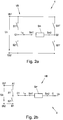
- Fig.2a shows a full bridge VB for energizing a drive coil Sm with a coil current i m .
- the drive coil Sm has a first coil connection Sm1 and a second coil connection Sm2.
- the full bridge VB consists of two main branches, the first main branch consisting of two switches S11, S21 which are connected in series to an operating voltage Ub, which is formed by the difference between a first operating potential Ub1 and a second operating potential Ub2 at the input connections of the full bridge VB becomes.
- the second main branch also consists of two switches S11 ', S21' which are connected in series to the operating voltage Ub.
- the first cross connection Q1 for a cross arm is located between the connection point of the first switch S11 and the second switch S21 of the first main branch. Equivalently, the second cross connection Q2 of the cross arm is located between the connection point of the first switch S11 'and the second switch S21' of the second main branch.
- the first coil connection Sm1 of the drive coil Sm is connected to the first cross connection Q1
- the second coil connection Sm2 of the drive coil Sm is connected to the second cross connection Q2.
- Half bridges HB can also be activated by the LLM controller 4 in order to energize the drive coils Sm with a coil current i m , for example as in FIG Figure 2b shown.
- the second main branch of the full bridge VB is dispensed with, which means that the Operating voltage Ub is only applied to the first main branch, between the first input connection A1 and the second input connection B1 and the first switch S11 and the second switch S21 connected in series therebetween.
- the connection point between the first S11 and the second switch S21 is referred to as the center point C1 and is connected to the first terminal Sm1 of the drive coil Sm.
- the second connection L12 of the drive coil Sm is at an electrical potential Ux, e.g.
- the second connections Sm2 of all drive coils Sm are usually connected to the control point C and are connected to the electrical potential Ux regulated, which usually corresponds to half the operating voltage Ub.
- a direct short circuit of the drive coil Sm through the two switches S11 and S12 is not possible when using a half bridge HB, since the switches S11 and S21 must never be closed at the same time.
- a “PWM short-circuit” is provided when using half-bridges HB.
- a PWM short circuit means that the upper switch S11 and the lower switch S21 of a half bridge HB are switched alternately, for example by means of 50/50 clocking over period T. This means that the same potential exists at both connections Sm1, Sm2 of the drive coil Sm Ux - analogous to the in Fig.
- a PWM short circuit does not correspond to a full short circuit at any point in time, but can be interpreted as a short circuit using a time integral of the coil voltage over a switching cycle.
- the drive coils Sm concerned are of course no longer supplied with the coil current i m by the control unit R.
- a coil short-circuit current icm is generated due to a voltage induced by an EMF (electro-magnetic force).
- the stator current i A corresponds to the vectorial total current of all coil currents i m
- the short-circuit current ic (in the dq coordinate system) also results as the vectorial total of the coil short-circuit currents icm.
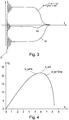
- Fig. 3 shows the time profile of a short-circuit current ic in the case of a permanent short-circuit during a braking process. It can be seen that the short-circuit current ic from the braking time O initially has a classic profile of a short-circuit current ic of a stator with oscillation behavior.
- Fig. 3 Also shown in Fig. 3 the course of the short-circuit current component icq that forms the propulsive force and the short-circuit current component icd that forms the field, that is to say pointing in the direction of the field, of the short-circuit current ic.
- the short-circuit current component icq generating propulsive force is responsible for braking the transport unit 1 in the same way as the propulsive force-generating current component iq is responsible for moving the transport unit 1 in the direction of movement x during normal operation. It is therefore desirable to additionally increase or maximize the short-circuit current component icq which forms the propulsive force during a regulated short-circuit mode M. This increase in the short-circuit current component icq, which forms the propulsive force, takes place through a suitable selection of the short-circuit and no-load phases.
- stator voltage equations formed for a multi-phase supply are assumed.
- the stator equations are solved for the speed and the stationary case (ie no changes over time, which in turn means a speed of zero) is assumed.
- the flux of the permanent magnet ⁇ can be assumed to be approximately constant.
- the relationship determined in this way is inserted into the force equation, whereupon the force equation is derived according to the short-circuit current ic.
- Setting the derived force equation to zero corresponds to an optimal relationship between the current component iq generating the propulsive force and the total short-circuit current ic, ie, maximizing the current component iq generating the propulsive force.
- the corresponding values for the inductance L and the flux ⁇ can be determined, for example, through experiments.
- Fig. 4 the approximated relationship of the braking force Fb as a function of the short-circuit current ic for a certain speed of the transport unit 1 is shown, with the short-circuit current ic plotted on the abscissa and the braking force Fb acting on the ordinate.
- the optimal target short-circuit current ic_soll is also drawn in and represents the short-circuit current ic, which results in a maximum braking force Fb, since the short-circuit current component icq, which forms the propulsive force, is maximized.
- all drive coils Sm, the drive coils Sm of a segment, or only the drive coils Sm coupled to the transport unit 1 (if known) can be used for short-circuited for a short period of time.
- the short-circuit current ic can be calculated as the vectorial sum of the coil short-circuit currents icm that are measured.
- Fig. 5 shows a typical period T in which the short-circuit interval tc_ks and idle interval tc_ll alternate.
- the period T is assumed to be constant here by way of example, but can of course also vary.
- the switches S11, S21, S11 ', S21' are open in the idle interval tc_ll and the switches S21 and S21 'or the switches S11 and S11' are switched through in the short-circuit interval tc_ks for a full short circuit.
- the idle interval tc_ll all four switches S11, S21 ', S11', S21 of the full bridge VB are open.
- the switches S11 and S21 are open in the idle interval tc_ll and alternately closed in the short-circuit interval tc_ks, for example in a 50/50 ratio.
- a short-circuit interval tc_ll of zero i.e. an idle interval tc_ll equal to period T
- a short-circuit interval tc_ll equal to period T and thus an idle interval tc_ll equal to zero
- the short-circuit interval tc_ll should, however, in particular in the case of a PWM short-circuit of a half-bridge HB, advantageously not be at zero, but rather just above it, preferably at the minimum protection time.
- the choice of the correct ratio of the short-circuit interval tc_ks to the idle interval tc_ll can be carried out by means of the short-circuit controller K, which can be connected upstream of the control unit R (as in Fig. 1 indicated), or can be an integral part of the control unit R.
- three phases A, B, C are provided in the regulated short-circuit mode M.
- a short-circuit phase A in which the short-circuit current ic is smaller than the target short-circuit current ic_soll multiplied by a factor a, ic ⁇ ic_ soll ⁇ a , the at least some of the drive coils Sm, which interact with a transport unit 1, Operated in short circuit over each period T, ie permanently, since the actual short-circuit current ic is smaller than the target short-circuit current ic_soll.
- this can mean a full short circuit, or when using half bridges HB in the LLM controller 4 it can mean a “PWM short circuit”.
- a minimum duration for the idle phase tc_ll (ie a maximum duration for the short-circuit phase tc_ks) can be provided for the short-circuit phase A, which can correspond to a predefined minimum protection time. For example, for a period T of 25 ⁇ s, the minimum duration of the idle phase tc_11 can correspond to a predefined minimum protection time, for example 500ns.
- a mixed phase B in which the short-circuit current ic equals or exceeds the target short-circuit current ic_soll multiplied by a factor a, ic ⁇ ic_soll ⁇ a , and advantageously less than the target short-circuit current ic_soll multiplied by (2-a): ic ⁇ ic_soll ⁇ (2 -a ) , the at least some of the drive coils Sm are operated alternately with a short circuit and with an open circuit. This means that in a period T short-circuit interval tc_ks and idle interval tc_ll alternate.
- the respective duration of the short-circuit interval tc_ks and idle interval tc_ll within a period T for the mixed phase B can be calculated using a third-order polynomial with an error deviation e_ic.
- the error deviation e_ic represents the deviation of the short-circuit current ic from the target short-circuit current ic_soll.
- the short-circuit controller K maximizes the idle interval tc_ll and minimizes the short-circuit interval tc_ks.
- the idle interval tc_ll can extend over the entire period T, so that the short-circuit interval tc_ks is zero. However, a minimum short-circuit interval tc_ks greater than zero or a maximum idle interval tc_ll less than the period T can also be provided. If, for example, a factor a of zero is selected, then only mixed phase B is used.
- the at least some of the drive coils Sm are operated alternately over a short circuit interval tc_ks in short circuit and over an idle interval tc_ll in idle mode, the duration of the short circuit interval tc_ks being determined by the duration of the idle interval tc_ll.
- a curve of the short-circuit current ic over the idle phase tc_ll is shown, with switching from the short-circuit phase A via the mixed phase B to the idle phase C.
- the idle interval tc_ll is not quite zero even in the short-circuit phase A, since a minimum duration is provided for the idle phase tc_ll.
- Fig.6b a curve of the error deviation e_ over the idle phase tc_ll from the idle phase C via the second phase B into the first short-circuit phase A is shown.
- Fig. 7 the time profile of a first short-circuit current ic1 for a permanent or 50/50 PWM short-circuit and a second short-circuit current ic2, which is generated according to the invention, is shown.
- a maximum short-circuit phase tc_ks is selected, ie a permanent phase A.
- a time profile of a first braking force Fb1 which results from the first short-circuit current ic1
- a time profile of a second braking force Fb2 which results from the second short-circuit current ic2.
- the second braking force Fb2 is higher than the first braking force Fb1, in particular immediately after the start of the braking process, although the second short-circuit current ic2 is less than the first short-circuit current ic1, which results from a short-circuit current component icq that increases the propulsive force according to the invention.
- the oscillation behavior of the second short-circuit current ic2 is improved.
- the selection of the drive coils Sm, which are controlled in accordance with the regulated short-circuit mode M, can basically be made freely. So all drive coils Sn or some of the drive coils Sn can be switched to the regulated short-circuit mode M.
- the drive coils Sm magnetically coupled to the transport unit T1 can advantageously be switched to the regulated short-circuit mode M.
- Which drive coils Sm are coupled to the transport unit 1 can be determined via the current position of the transport unit 1.
- This position detection can take place by means of suitable position sensors, which can already be provided on the long stator linear motor, for example as in FIG AT 519 238 A1 described.
- drive coils Sm carry a coil short-circuit current icm (which is measured) in the short-circuited state. From this it can be concluded which of the drive coils Sm are magnetically coupled to the transport unit 1.
- this drive coil Sm can also be used in the Short circuit mode M can be switched.
- this has the consequence that a drive coil Sm is no longer coupled to the transport unit 1 against the direction of movement x, which means that it no longer has to remain in short-circuit mode M.
- the fact that the drive coil Sm is no longer coupled to the transport unit 1 counter to the direction of movement x can, however, also be detected via position sensors or non-induction of a coil short-circuit current icm.
- the short-circuit controller K can limit the short-circuit current ic, for example to a threshold value icmax. This can be done by switching from the short circuit to the open circuit. It is thus possible to regulate the (average) short-circuit current ic - as long as there is enough kinetic energy in the transport unit 1.
Landscapes
- Engineering & Computer Science (AREA)
- Power Engineering (AREA)
- Physics & Mathematics (AREA)
- Electromagnetism (AREA)
- Transportation (AREA)
- Mechanical Engineering (AREA)
- Microelectronics & Electronic Packaging (AREA)
- Chemical & Material Sciences (AREA)
- Combustion & Propulsion (AREA)
- Control Of Linear Motors (AREA)
- Non-Mechanical Conveyors (AREA)
- Linear Motors (AREA)
Description
- Die gegenständliche Erfindung betrifft ein Verfahren zum Ansteuern einer Mehrzahl von Antriebspulen eines Langstatorlinearmotors, wobei die Antriebspulen in einem Normalbetrieb derart bestromt werden, dass ein mit einer Transporteinheit gekoppeltes Magnetfeld entlang einer Bewegungsrichtung bewegt wird um die Transporteinheit entlang der Bewegungsrichtung zu bewegen, wobei bei einem Bremsvorgang der Transporteinheit in einen geregelten Kurzschlussmodus geschaltet wird, in welchem zumindest ein Teil der Antriebspulen zumindest über einen ersten Zeitabschnitt in einem Kurzschluss betrieben wird. Die gegenständliche Erfindung betrifft ebenso einen Langstatorlinearmotor mit einer Mehrzahl Antriebspulen und zumindest einer Transporteinheit, wobei eine über einen Spulenregler gesteuerte LLM-Steuerung vorgesehen ist, die ausgestaltet ist die Antriebspulen derart zu bestromen, dass ein mit der Transporteinheit gekoppeltes Magnetfeld entlang einer Bewegungsrichtung bewegt wird um die Transporteinheit entlang der Bewegungsrichtung zu bewegen.
- Um den Anforderungen moderner, flexibler Logistikeinheiten gerecht zu werden, werden vermehrt Langstatorlinearmotoren (LLM) als Ersatz für konventionelle Stetigförderer, beispielsweise rotativ-zu-linear Übersetzeinheiten, wie beispielsweise rotative Motoren an einem Förderband, eingesetzt. Langstatorlinearmotoren zeichnen sich durch eine bessere und flexiblere Ausnützung über den gesamten Arbeitsbereich aus. So können die Bereiche der Geschwindigkeit und Beschleunigung von Null bis zum Maximum ausgenutzt werden. Zudem sind eine individuelle Regelung bzw. Steuerung der beweglichen Transporteinheiten (Shuttles), eine verbesserte Energieausnützung, die Reduktion der Wartungskosten aufgrund der geringeren Anzahl an Verschleißteilen, eine einfacher Austausch der Transporteinheiten, ein effizientes Monitoring und eine einfachere Fehlerdetektion, eine Optimierung des aufgenommen Stromes durch Eliminierung von Stromlücken als Vorteile aufzuzählen.
- Ein Stator eines Langstatorlinearmotors besteht aus einer Vielzahl von in Bewegungsrichtung der Transporteinheiten nebeneinander angeordneten Antriebspulen, die zusammen den Stator des Langstatorlinearmotors bilden. Diese Antriebspulen werden einzeln oder in Gruppen angesteuert, wobei es im Betrieb des Langstatorlinearmotors oftmals auch erwünscht oder notwendig ist die Polarität, d.h. die Stromrichtung der Antriebspulen zu ändern. Durch das Ansteuern der Antriebspulen wird ein bewegtes Magnetfeld erzeugt, das mit Erregungsmagneten (in der Regel Permanentmagnete) an einer Transporteinheit des LLM zusammenwirkt, um eine Vortriebskraft auf die Transporteinheit zu erzeugen und die Transporteinheit so entlang des Stators zu bewegen. Zum Bestromen der Antriebspulen zur Erzeugung des Magnetfeldes wird in der Regel eine Betriebsspannung zwischen einem ersten Betriebspotential und einem zweiten Betriebspotential zur Verfügung gestellt. Solche Langstatorlinearmotoren sind in verschiedenen Ausgestaltungen hinlänglich bekannt, beispielsweise aus der
WO 2013/143783 A1 , derUS 6,876,107 B2 , derUS 2013/0074724 A1 oder derWO 2004/103792 A1 , um nur einige zu nennen. - Eine Möglichkeit Antriebspulen anzusteuern und eine Änderung der Polarität der Spulenspannung zu ermöglichen wäre die Verwendung einer Vollbrücke, wie sie in der
US 2006/0220623 A1 offenbart ist. Die Betriebsspannung wird dabei jeweils an den ersten und zweiten Zweig der Vollbrücke angelegt, die Antriebspule wird in den Querzweig der Vollbrücke geschaltet. Durch geeignete Ansteuerung der vier Schalter (Bipolar-Transistoren, MOS-FETs, IGBTs, etc.) der Vollbrücke kann an die Antriebspulen eine gewünschte, bzw. durch eine Spulenregelung vorgegebene, Spulenspannung in gewünschter Polarität und Höhe an die Antriebspulen angelegt werden. Um die Antriebspulen einzeln ansteuern zu können, muss jede Antriebspule mit einer Vollbrücke versehen werden. Dies bedeutet jedoch, dass pro Antriebspule vier Schalter benötigt werden. Bei einer naturgemäß hohen Anzahl an Antriebspulen eines LLM-Stators entstehen somit hohe Kosten und ein hoher schaltungstechnischer Aufwand durch die hohe Anzahl an Schaltern. - Die
AT 518 721 A1 - Es kann erwünscht sein eine Transporteinheit schnell abzubremsen. In Ausnahmesituationen, wie bei Gefährdung der Sicherheit von Personen im Bereich des Langstatorlinearmotors, Überbelastungen des Systems, Spannungsüberhöhungen aber auch z.B. Verlust der Positions- bzw. Geschwindigkeitsinformation, kann es z.B. notwendig sein einen sofortigen Notstopp einzuleiten, womit alle oder ein Teil der Transporteinheiten (z.B. alle Transporteinheiten eines gewissen Sektors) zum Stillstand gebracht werden müssen. Die
US 2012/193172 offenbart beispielsweise spezielle an einem Linearmotor angebrachte Bremswindungen zum Erzeugen einer Bremswirkung. Solche zusätzlichen Bremswindungen erhöhen aber den konstruktiven Aufwand und die Kosten für den Langstatorlinearmotors und sind demnach unerwünscht. - Die
EP 0294 541 A1 beschreibt einen Linearmotor, welcher eine Kurzschlussbremsung, d.h. einen Bremsvorgang durch Kurzschließen von Spulen, aufweist. DieEP 0 289 686 A2 beschreibt zwar ein Kurzschließen von Spulen, jedoch keinen damit verbundenen Bremsvorgang. DieDE 22 35 705 A1 offenbart eine Transporteinheit, welche eine Kurzschlussbremsung aufweist. - Es ist eine Aufgabe der gegenständlichen Erfindung auf einfache Weise ein sicheres Abbremsen einer Transporteinheit eines Langstatorlinearmotors zu ermöglichen.
- Diese Aufgabe wird erfindungsgemäß gelöst, indem im geregelten Kurzschlussmodus der zumindest eine Teil der Antriebspulen zumindest über einen zweiten Zeitabschnitt in einem Leerlauf betrieben wird.. Die Aufgabe wird ebenso durch einen Kurzschlussregler gelöst, der ausgestaltet ist bei einem Bremsvorgang der Transporteinheit zumindest einen Teil der Antriebspulen zumindest über einen ersten Zeitabschnitt kurzschließen und zumindest über einen zweiten Zeitabschnitt in einem Leerlauf zu betreiben.
- Nachdem ein Bremsvorgang einer Transporteinheit eingeleitet wurde, werden üblicherweise die relevanten Antriebsspulen stromlos geschaltet (was im Grunde einem Leerlauf entspricht) um die Transporteinheit nicht mehr aktiv weiterzubewegen. Die Transporteinheit bewegt sich jedoch ohne geeignete Aktionen entlang des Stators des Langstatorlinearmotors bis zum Stillstand mit geringer Verzögerung (aufgrund der erwünschten reibungsarmen Lagerung bzw. Führung der Transporteinheiten an der Transportstrecke) weiter, was unerwünscht ist, da die Transporteinheiten in der Regel sehr rasch zum Stillstand gebracht werden sollen. Bei Weiterbewegung einer Transporteinheit wird über ein durch die Erregungsmagnete selbst ein bewegtes Magnetfeld erzeugt. Dieses Magnetfeld bewegt sich mit der Transporteinheit entlang des Stators und weist damit auch die Geschwindigkeit der Transporteinheit auf. Dabei wirkt dieses Magnetfeld auch mit den Antriebspulen des Stators zusammen, was bei offenen Klemmen der Antriebsspulen keinen Effekt hätte. Die Antriebspulen, die mit der Transporteinheit magnetisch gekoppelt sind, induzieren jedoch bei kurzgeschlossenen Klemmen über eine Elektro-Magnetische-Kraft (EMK) jeweils einen Spulenkurzschlussstrom. Dieser Spulenkurzschlussstrom wirkt nach der Lenz'schen Regel dem durch die Transporteinheit hervorgerufenen Magnetfeld entgegen, womit die Transporteinheit relativ rasch abgebremst wird. Somit wird der Kurzschluss des zumindest einen Teils der Antriebspulen vorzugsweise während des gesamten Bremsvorgangs, d.h. bis zum Stillstand der Transporteinheit aufrechterhalten. Das würde bedeuten, dass der erste Zeitabschnitt sich über den gesamten Bremsvorgang erstreckt, wobei der Kurzschluss nach dem Stillstand der Transporteinheit aufgehoben werden kann. Wenn der erste Zeitabschnitt kürzer gewählt wird, dann kann die Transporteinheit zumindest auf eine unkritische Geschwindigkeit abgebremst werden, aus der die Transporteinheit dann z.B. "ausrollen" kann.
- Bei einem Kurzschluss sind die betreffenden Spulenklemmen geschlossen, bei einem Leerlauf sind die betreffenden Spulenklemmen geöffnet. Bei geeigneter Wahl des ersten und zweiten Zeitabschnitts kann der Kurzschlussstrom (als Summe der jeweils fließenden Spulenkurzschlussströme) derart geregelt werden, dass eine größere Stromkomponente in Kraftrichtung (d.h. in einem kartesischen feldorientierten dq-Koordinatensystem in q-Richtung) erreicht wird. Damit wird der Anteil des Kurzschlussstroms, welcher der der Vortriebsbewegung dienenden Feldrichtung entgegenwirkt, erhöht, womit eine größere Bremswirkung als bei einem dauerhaften Kurzschluss erzielt wird und womit die Transporteinheit noch schneller zum Stillstand kommt. Somit kann selbst bei geringeren Kurschlussströmen eine höhere Bremskraft und damit eine bessere und raschere Abbremsung der Transporteinheit erzielt werden. Zudem werden eine geringere Strombelastung und eine geringere Feldschwächung erreicht. Eine geringere Feldschwächung bedingt zudem eine geringere Normalkraftabnahme, womit unter Umständen zusätzlich verhindert werden kann, dass die Transporteinheit bei einer bestimmten Geschwindigkeit z.B. in einem Kurvenbereich der Transportstrecke vom Stator abheben kann.
- Vorteilhafterweise wird ein gesamter durch die Antriebspulen fließender Kurzschlussstrom ermittelt und ein Soll-Kurzschlussstrom mit einer maximalen vortriebskraftbildende Kurzschlussstromkomponente icq mittels einer vorgegebenen Beziehung ermittelt. Im geregelten Kurzschlussmodus kann in einer Kurzschlussphase, in welcher der Kurzschlussstrom kleiner als der Soll-Kurzschlussstrom ist, der zumindest eine Teil der Antriebspulen im Kurzschluss betrieben werden. In einer Leerlaufphase, in welcher der Kurzschlussstrom dem Soll-Kurzschlussstrom erreicht oder überschreitet, kann der zumindest eine Teil der Antriebspulen im Leerlauf betrieben werden.
- Es kann aber im geregelten Kurzschlussmodus in einer Kurzschlussphase, in welcher der Kurzschlussstrom kleiner als der Soll-Kurzschlussstrom multipliziert mit einem Faktor ist, der zumindest eine Teil der Antriebspulen im Kurzschluss betrieben werden. In einer Mischphase, in welcher der Kurzschlussstrom dem Soll-Kurzschlussstrom multipliziert mit einem Faktor entspricht oder überschreitet, wird der zumindest eine Teil der Antriebspulen abwechselnd im Kurzschluss und im Leerlauf betrieben. In einer Leerlaufphase, in welcher der Kurzschlussstrom dem Soll-Kurzschlussstrom multipliziert mit dem Term 2 minus Faktor a entspricht oder überschreitet, wird der zumindest eine Teil der Antriebspulen im Leerlauf betrieben.
- Vorzugsweise entspricht die vorgegebene Beziehung f:

- Es kann in der Mischphase der zumindest eine Teil der Antriebspulen jeweils abwechselnd über ein Kurzschlussintervall im Kurzschluss betrieben werden und über ein Leerlaufintervall im Leerlauf betrieben wird, wobei die Dauer des Kurzschlussintervalls zur Dauer des Leerlaufintervalls bestimmt und vorteilhafterweise über ein Polynom dritter Ordnung mit einer Fehlerabweichung berechnet wird.
- Weiters kann ein Faktor von 0.85 gewählt werden, welcher eine besonders gute Bremswirkung bewirkt, wie sich auch in der Praxis bestätigt hat.
- Ganz besonders vorteilhaft ist es, wenn nur die mit der Transporteinheit magnetisch gekoppelten Antriebspulen in den geregelten Kurzschlussmodus geschaltet werden. Damit müssen nicht alle Antriebsspulen des gesamten Langstatorlinearmotors in den Kurzschlussmodus geschaltet werden. So kann beispielsweise nach Bedarf auch nur eine Transporteinheit abgebremst werden, wogegen die weiteren Transporteinheiten vom Bremsvorgang nicht betroffen sind.
- Hierzu können die mit der Transporteinheit magnetisch gekoppelten Antriebspulen mittels eines Positionssensors bestimmt werden. Dies kann vorteilhaft sein, wenn ohnehin bereits Positionssensoren am Langstatorlinearmotor vorgesehen sind.
- Die mit der Transporteinheit magnetisch gekoppelten Antriebspulen können aber auch über einen in der jeweiligen Antriebsspule induzierten Spulenkurzschlussstrom erkannt werden. Dieser induzierte Spulenkurzschlussstrom lässt auf eine magnetische Kopplung mit einer Transporteinheit schließen.
- Natürlich können je nach Wunsch auch weitere Antriebsspulen in den geregelten Kurzschlussmodus geschaltet werden, beispielsweise eine bestimmte Anzahl an Antriebsspulen, die sich in Bewegungsrichtung vor der Transporteinheit befinden, etc.
- Die Dauer des Bremsvorgangs ist, neben der Wahl des ersten bzw. zweiten Zeitabschnitts, von der Masse der Transporteinheit, wie auch von an die Transporteinheit gebundene zusätzliche Massen (Transportgut, Werkstück,...) und/oder der Geschwindigkeit der Transporteinheit abhängig. Die Energie, die während des Bremsvorgangs frei wird, wird vorwiegend in den Wicklungswiderständen (Kupferverluste) und im Eisen (vorwiegend Wirbelstromverluste) in Wärme umgesetzt.
- Ein Kurzschluss kann für unterschiedliche Ausgestaltung einer LLM-Steuereinheit unterschiedliche Schalterstellungen bedeuten. Weist die LLM-Steuereinheit Vollbrücken, wie in der
US 2006/0220623 A1 , mit jeweils vier Schaltern pro Antriebspule auf, so kann während des geregelten Kurzschlusses in der Kurzschlussphase, bzw. dem Kurzschlussintervall ein satter Kurzschluss geschaltet werden. Weist die LLM-Steuereinheit jedoch Halbbrücken, umfassend einen oberen und einen unteren Schalter pro Antriebsspule, auf (sieheAT 518 721 A1 - Die gegenständliche Erfindung wird nachfolgend unter Bezugnahme auf die
Figuren 1 bis 7 näher erläutert, die beispielhaft, schematisch und nicht einschränkend vorteilhafte Ausgestaltungen der Erfindung zeigen. Dabei zeigt -
Fig.1 einen Langstatorlinearmotoraufbau, -
Fig.2a eine Vollbrücke zur Ansteuerung einer Antriebsspule, -
Fig.2b eine Halbbrücke zur Ansteuerung einer Antriebsspule, -
Fig.3 einen zeitlichen Verlauf des momentbildenden Kurschlussstromes, des feldbildenden Kurzschlussstromes und des Kurzschlussstroms, von mehreren überdecken Spulen zusammengefasst. -
Fig.4 eine Approximation der Bremskraft als Funktion des Kurzschlussstroms, -
Fig.5 ein typisches Schaltmuster für das Kurzschlussintervall und das Leerlaufintervall, -
Fig.6a und b Verläufe des Kurzschlussintervalls über den Kurzschlussstrom und die Fehlerabweichung -
Fig.7 einen zeitlichen Verlauf eines ersten und zweiten Kurschlussstromes mehrerer Spulen und einer ersten und zweiten erzeugten Bremskraft. -
Fig.1 stellt ein einfaches Beispiel eines Langstatorlinearmotors 2 dar. Der Langstatorlinearmotor 2 ist dabei als geschlossene Transportstrecke 20 ausgeführt. Auf der Transportstrecke 20 sind eine Vielzahl m von Antriebsspulen Sm in Bewegungsrichtung x einer Transporteinheit 1 hintereinander angeordnet, die im Normalbetrieb unter Kontrolle einer Spulenregelung R (nur für einige Antriebsspulen Sm dargestellt) jeweils mit einem Spulenstrom im bestromt werden, um ein bewegtes Magnetfeld zu erzeugen. Es ist zudem eine LLM-Steuereinheit 4 vorgesehen, die hier integraler Bestandteil der Spulenregelung R ist. Die mit im gekennzeichneten Pfeile sind dabei natürlich nur schematisch zu sehen. Es können die Antriebsspulen Sm auch auf andere Weise mit der Steuereinheit verbunden sein um die Antriebsspulen Sm mit dem Spulenstrom im zu bestromen, wie weiter unten anhand derFig. 2a, 2b beispielhaft dargestellt. Sowohl die Spulenregelung R als auch die LLM-Steuereinheit 4 kann als geeignete Hardware (auch dieselbe) und/oder als auf einer geeigneten Hardware laufenden Software ausgeführt sein. Die LLM-Steuereinheit 4 weist pro Antriebsspule Sm Vollbrücken VB (bestehend aus vier Schaltern) oder Halbbrücken HB (bestehend aus zwei Schaltern) auf und kann auch aus mehreren Untereinheiten bestehen, die auch direkt an den Antriebsspulen Sm angeordnet sein können. Durch die Schalterstellungen der Schalter der Vollbrücken VB bzw. Halbbrücken HB der LLM-Steuereinheit 4 werden die Antriebsspulen Sm im Normalbetrieb mit dem Spulenstrom im versorgt oder vom Spulenstrom im getrennt. - Die in Bewegungsrichtung x nebeneinander angeordneten Antriebsspulen Sm sind an einer ortsfesten Haltekonstruktion 3 (in
Fig.1 nur angedeutet) an der Transportstrecke 20 angeordnet. Die Transporteinheiten 1 werden entlang der Transportstrecke 20 in einer Bewegungsrichtung x bewegt, und sind dazu jeweils auf geeignete Weise an der stationär angeordneten Transportstrecke 20 geführt und gehalten. - Eine Transporteinheit 1 weist entlang der Bewegungsrichtung x seitlich angeordnete erste Magnete M1 auf und kann wie in
Fig. 1 dargestellt zudem seitlich angeordnete Magnete M2 aufweisen, die sich in einer Querrichtung quer zur Bewegungsrichtung x gegenüber den ersten Magneten M1 befinden können. Weist die Transporteinheit 1 an zwei Seiten jeweils erste Magnete M1 bzw. zweite Magnete M2 auf, so können passend dazu an beiden Seiten der Transportstrecke 20 (in Bewegungsrichtung x gesehen) jeweils Antriebsspulen Sm vorgesehen sein, die mit den jeweiligen Magneten M1, M2 zusammenwirken um eine Bewegung der Transporteinheiten 1 zu verursachen. Zur Bewegung werden vorzugsweise nur die Antriebsspulen Sm im Bereich der Magnete M1, M2 von der Spulenregelung R mit Strom versorgt, wobei dieser Bereich auch Antriebspulen Sm umfassen kann, die sich vor und/oder nach der Transporteinheit 1 befinden. Selbstverständlich können entlang der Transportstrecke 20 auch mehr als eine Transporteinheit 1 bewegt werden, wobei jede Transporteinheit 1 durch entsprechendes Bestromen der Antriebsspulen Sm im Bereich der Transporteinheit 1 unabhängig von den anderen Transporteinheiten 1 (in Richtung, Position, Geschwindigkeit und Beschleunigung) bewegt werden kann. Um die Position der Transporteinheit 1 am Stator und damit die aktuell zu bestromenden Spulen Sm, die sich entlang der Transportstrecke bei der Transporteinheit 1 befinden. zu bestimmen, können beispielsweise Stromsensoren vorgesehen sein. - Die Transportstrecke 20 kann dabei, je nach Anwendung und Bedarf, beliebig geformt sein und kann geschlossene und/oder offene Streckenabschnitte umfassen. Die Transportstrecke 20 muss nicht in einer Ebene liegen, sondern kann auch beliebig im Raum geführt sein. Üblicherweise besteht eine Transportstrecke 20 aus mehreren zusammengesetzten Transportsegmenten mit jeweils einer Anzahl von Antriebsspulen Sm. Gleichfalls sind auch Weichen bekannt, um eine Transporteinheit 1 von einer ersten Transportstrecke 20 auf eine zweite Transportstrecke 20 zu führen. Die für die Bewegung der Transporteinheit 1 benötigte Vortriebskraft wird bekanntermaßen von der vortriebskraftbildenden Stromkomponente iq (q-Komponente) eines Statorstromes iA gebildet. Der Statorstrom iA ist ein Stromvektor mit einer q- und einer d-Komponente (normalkraftbildende Stromkomponente) und entspricht dem vektoriellen Summenstrom aller Spulenströme im der auf die Transporteinheit 1 wirkenden Antriebsspulen Sm. Für die normale Vorwärtsbewegung der Transporteinheit 1 reicht somit die vortriebskraftbildende Stromkomponente iq (q-Komponente) aus. Die nicht der Vorwärtsbewegung dienende Normalkraft wird von der normalkraftbildenden Stromkompente id (d-Komponente) des Statorstroms iA gebildet. In einem Langstatorlinearmotor wirken meist mehrere Antriebsspulen Sm gleichzeitig auf die Transporteinheit 1 um eine Bewegung in der Bewegungsrichtung x zu erzielen. Wenn keine d-Komponenten vorhanden sind, entspricht die vortriebskraftbildende Stromkomponente iq dem vektorieller Summenstrom aller Spulenströme im der auf die Transporteinheit 1 wirkenden Antriebsspulen Sm. Die im Spulenregler R berechnete vortriebskraftbildende Stromkomponente iq muss daher noch auf die tatsächlich wirkenden Spulenströme im der Antriebsspulen Sm umgerechnet und aufgeteilt und daran angelegt werden, was hinlänglich bekannt ist. Das grundlegende Funktionsprinzip eines Langstatorlinearmotors 2 ist hinlänglich bekannt, sodass hier nicht weiter darauf eingegangen wird.
- Im Rahmen eines Bremsvorgangs kann eine Transporteinheit 1 abgebremst werden, indem entsprechende Antriebsspulen Sm, z.B. die mit der Transporteinheit 1 zusammenwirkenden, oder alle Antriebsspulen Sm, oder beispielsweise in Bewegungsrichtung angeordnete Antriebsspulen Sm, etc., kurzgeschlossen werden. Hierzu werden beispielsweise die Schalter der Vollbrücken VB/Halbbrücken HB von der LLM-Steuereinheit 4 in die geeignete Stellung gebracht, was durch einen Kurzschlussregler K initiiert werden kann. Der Kurzschluss kann aber natürlich noch auf andere Weise erzeugt werden, beispielsweise durch einen Schalter parallel zu den Antriebsspulen Sm. "Kurzgeschlossen" kann bei Verwendung von Vollbrücken in der LLM-Steuerung 4 einen satten Kurzschluss bedeuten.
-
Fig.2a zeigt eine Vollbrücke VB zum Bestromen einer Antriebsspule Sm mit einem Spulenstrom im. Die Antriebsspule Sm weist einen ersten Spulenanschluss Sm1 und einen zweiten Spulenanschluss Sm2 auf. Die Vollbrücke VB besteht aus zwei Hauptzweigen, wobei der erste Hauptzweig aus zwei Schaltern S11, S21 besteht, die in Serie an einer Betriebsspannung Ub liegen, welche durch die Differenz aus einem ersten Betriebspotential Ub1 und einem zweiten Betriebspotential Ub2 an den Eingangsanschlüssen der Vollbrücke VB gebildet wird. Auch der zweite Hauptzweig besteht aus zwei Schaltern S11', S21', die in Serie an der Betriebsspannung Ub liegen. Zwischen dem Verbindungspunkt des ersten Schalters S11 und des zweiten Schalters S21 des ersten Hauptzweiges befindet sich der erste Queranschluss Q1 für einen Querzweig. Äquivalent befindet sich zwischen dem Verbindungspunkt des ersten Schalters S11' und des zweiten Schalters S21' des zweiten Hauptzweiges der zweite Queranschluss Q2 des Querzweigs. Der erste Spulenanschluss Sm1 der Antriebsspule Sm ist mit dem ersten Queranschluss Q1 verbunden, der zweite Spulenanschluss Sm2 der Antriebsspule Sm ist mit dem zweiten Queranschluss Q2 verbunden. Durch geeignetes Ansteuern der Schalter S11, S21, S11', S21' durch die LLM-Steuerung 4 (hier nicht eingezeichnet) kann zwischen erstem Spulenanschluss Sm1 und zweitem Spulenanschluss Sm2 das gleiche elektrische Potential anliegt, während der Spulenstrom im fließt. Bei einem satten Kurzschluss werden somit die Schalter S11 und S11' durchgeschaltet (bei offenen Schaltern S21 und S21') oder die Schalter S21, S21' durchgeschaltet (bei offenen Schaltern S11, S11'). - Es können von der LLM-Steuerung 4 auch Halbbrücken HB angesteuert werden um die Antriebsspulen Sm mit einem Spulenstrom im zu bestromen, beispielsweise wie in
Fig. 2b dargestellt. Es wird dabei auf den zweiten Hauptzweig der Vollbrücke VB verzichtet, womit die Betriebsspannung Ub nur am ersten Hauptzweig, zwischen dem ersten Eingangsanschluss A1 und zweitem Eingangsanschluss B1 und dem dazwischen in Serie geschalteten ersten Schaltern S11 und zweiten Schalter S21 anliegt. Der Verbindungspunkt zwischen erstem S11 und zweitem Schalter S21 wird als Mittelpunkt C1 bezeichnet und ist mit dem ersten Anschluss Sm1 der Antriebsspule Sm verbunden. Der zweite Anschluss L12 der Antriebsspule Sm liegt auf einem, z.B. von einer Potentialregelungseinheit vorgegebenen, elektrischen Potential Ux an einem Regelungspunkt C. Üblicherweise sind die zweiten Anschlüsse Sm2 aller (hier nicht eingezeichneten) Antriebsspulen Sm mit dem Regelungspunkt C verbunden und werden auf das elektrische Potential Ux geregelt, das üblicherweise der halben Betriebsspannung Ub entspricht. - Ein direkter Kurzschluss der Antriebsspule Sm durch die beiden Schalter S11 und S12 ist bei Verwendung einer Halbbrücke HB nicht möglich, da die Schalter S11 und S21 nie gleichzeitig geschlossen sein dürfen. Um die Betriebsspannung Ub nicht kurzzuschließen ist bei Verwendung von Halbbrücken HB somit ein "PWM-Kurzschluss" vorgesehen. Ein PWM-Kurzschluss bedeutet, dass jeweils der obere Schalter S11 und der unteren Schalter S21 einer Halbbrücke HB abwechselnd geschaltet werden, beispielsweise mittels einer 50/50-Taktung über Periodendauer T. Damit herrscht an beiden Anschlüssen Sm1, Sm2 der Antriebsspule Sm das gleiche Potential Ux - analog zur in
Fig. 2a dargestellten Vollbrücke VB, bei welcher sich bei einem satten Kurzschluss beide Spulenanschlüsse Sm1, Sm2 entweder auf dem ersten Betriebspotential Ub1 oder dem zweiten Betriebspotential Ub2 befinden. Beim Wechsel der geschlossenen/geöffneten Schalter einer Halbbrücke HB kann eine minimale Schutzzeit eingehalten werden um eventuell vorhandene Restladungen auszuräumen. - Ein PWM-Kurzschluss entspricht zu keinem Zeitpunkt einem satten Kurzschluss, kann jedoch über ein zeitliches Integral der Spulenspannung über einen Schaltzyklus als Kurzschluss interpretiert werden. Dabei werden die betreffenden Antriebsspulen Sm natürlich nicht mehr von der Regelungseinheit R mit dem Spulenstrom im versorgt. Es entsteht in den mit der Transporteinheit 1 gekoppelten Antriebsspulen Sm jedoch aufgrund der weiteren Bewegung in Bewegungsrichtung x jeweils ein Spulenkurzschlussstrom icm aufgrund einer durch eine EMK (Elektro-Magnetischen-Kraft) induzierten Spannung.
- Da der Statorstrom iA (im dq-Koordinatensystem) dem vektoriellen Summenstrom aller Spulenströme im entspricht, ergibt sich auch der Kurzschlussstrom ic (im dq-Koordinatensystem) als vektorielle Summe der Spulenkurzschlussströme icm.
Fig. 3 zeigt den zeitlichen Verlauf eines Kurzschlussstromes ic bei einem dauerhaften Kurzschluss während eines Bremsvorgangs. Es ist ersichtlich, dass der Kurzschlussstrom ic ab dem Bremszeitpunkt O anfangs einen klassischen Verlauf eines Kurzschlussstroms ic eines Stators mit Schwingverhalten aufweist. So tritt nach einem subtransienten Verlauf ein transienter Verlauf ein, woraufhin schließlich ein annähernd konstanter Verlauf folgt, welcher wiederum schlussendlich abfällt und gegen Null strebt. Dieser Abfall wird dadurch hervorgerufen, dass die treibende Elektro-Magnetische-Kraft (EMK) verringert wird, da die Geschwindigkeit der Transporteinheit 1 zu diesem Zeitpunkt bereits gering ist. - Ebenso abgebildet sind in
Fig. 3 der Verlauf der vortriebskraftbildenden Kurzschlussstromkomponente icq und der feldbildende, d.h. in Feldrichtung zeigende, Kurzschlussstromkomponente icd, des Kurzschlussstroms ic. Die vortriebskraftbildende Kurzschlussstromkomponente icq ist dabei in gleicher Weise für die Bremsung der Transporteinheit 1 verantwortlich, wie es die vortriebskraftbildende Stromkomponente iq im Normalbetrieb für die Bewegung der Transporteinheit 1 in Bewegungsrichtung x ist. Daher ist es wünschenswert die vortriebskraftbildende Kurzschlussstromkomponente icq während eines geregelten Kurzschlussmodus M zusätzlich zu vergrößern, bzw. zu maximieren. Diese Vergrößerung der vortriebskraftbildenden Kurzschlussstromkomponente icq erfolgt durch geeignete Wahl der Kurzschluss- und Leerlaufphasen. - Es kann eine Abschätzung des Zusammenhangs zwischen vortriebskraftbildender Stromkomponente iq als Funktion des gesamten Kurzschlussstromes ic gebildet werden, ohne eine zusätzliche Information bezüglich der Position bzw. Winkel zu benötigen. Hierzu wird von für eine mehrphasige Anspeisung gebildeten Ständerspannungsgleichungen ausgegangen. Es werden die Ständergleichungen nach der Geschwindigkeit aufgelöst und der stationäre Fall (d.h. keine Änderungen über die Zeit, was wiederum eine Geschwindigkeit von Null bedeutet) angenommen. Unter Berücksichtigung des Zusammenhangs


- Der optimale Soll-Kurzschlussstrom ic_soll mit einer maximalen vortriebskraftbildenden Kurzschlussstromkomponente icq kann somit ausgehend von den Ständerspannungsgleichungen nach der Beziehung f:

- Die entsprechenden Werte für die Induktivität L und den Fluss Ψ, können beispielsweise durch Versuche bestimmt werden.
- In
Fig. 4 ist der approximierte Zusammenhang der Bremskraft Fb als Funktion des Kurschlussstromes ic für eine gewisse Geschwindigkeit der Transporteinheit 1 dargestellt, wobei auf der Abszisse der Kurzschlussstrom ic aufgetragen ist und auf der Ordinate die wirkende Bremskraft Fb. Der optimale Soll-Kurzschlussstrom ic_soll ist ebenso eingezeichnet und stellt den Kurzschlussstrom ic dar, der eine maximale Bremskraft Fb ergibt, da die vortriebskraftbildende Kurzschlussstromkomponente icq maximiert ist. - Um zu Beginn eines Bremsvorgangs, aber auch in jedem Zyklus nach dem Start des Bremsvorgangs den Ist-Kurzschlussstrom ic zu bestimmen, können alle Antriebspulen Sm, die Antriebspulen Sm eines Segments, oder nur die mit der Transporteinheit 1 gekoppelten Antriebsspulen Sm (sofern bekannt) für einen kurzen Zeitraum kurzgeschlossen werden. Der Kurzschlussstrom ic kann als vektorielle Summe der Spulenkurzschussströme icm, die gemessen werden, berechnet werden.
-
Fig. 5 zeigt eine typische Periode T, in welcher sich Kurzschlussintervall tc_ks und Leerlaufintervall tc_ll abwechseln. Die Periode T ist hier beispielhaft als konstant angenommen, kann aber natürlich auch variieren. - Bei Verwendung einer Vollbrücke VB (vgl.
Fig 2a ) sind die Schalter S11, S21, S11', S21' im Leerlaufintervall tc_ll geöffnet und im Kurzschlussintervall tc_ks für einen satten Kurzschluss die Schalter S21 und S21' oder die Schalter S11 und S11' durchgeschaltet. Im Leerlaufintervall tc_ll sind alle vier Schalter S11, S21', S11', S21 der Vollbrücke VB geöffnet. Bei Verwendung einer Halbbrücke HB (vgl.Fig. 2b ) sind die Schalter S11 und S21 im Leerlaufintervall tc_ll geöffnet und im Kurzschlussintervall tc_ks jeweils abwechselnd, z.B. in einem 50/50-Verhältnis, geschlossen. - Als Grenzfälle wäre ein Kurzschlussintervall tc_ll von Null (d.h. ein Leerlaufintervall tc_ll in der Höhe der Periode T) oder ein Kurzschlussintervall tc_ll in der Höhe der Periode T (und damit ein Leerlaufintervall tc_ll von Null) vorstellbar. Das Kurzschlussintervall tc_ll sollte jedoch insbesondere bei einem PWM-Kurzschluss einer Halbbrücke HB vorteilhafterweise nicht bei Null liegen, sondern knapp darüber, vorzugsweise bei der minimalen Schutzzeit.
- Die Wahl des richtigen Verhältnisses von Kurzschlussintervall tc_ks zu Leerlaufintervall tc_ll kann mittels des Kurzschlussreglers K durchgeführt werden, welcher der Regelungseinheit R vorgeschaltet sein kann (wie in
Fig.1 angedeutet), oder integraler Bestandteil der Reglungseinheit R sein kann. - Vorteilhafterweise werden im geregelten Kurzschlussmodus M drei Phasen A, B, C vorgesehen. In einer Kurzschlussphase A, in welcher der Kurzschlussstrom ic kleiner als der Soll-Kurzschlussstrom ic_soll multipliziert mit einem Faktor a ist, ic < ic_soll · a, wird der zumindest eine Teil der Antriebspulen Sm, die mit einer Transporteinheit 1 zusammenwirken, über jede Periodendauer T, d.h. dauerhaft, im Kurzschluss betrieben, da der Ist-Kurzschlussstrom ic kleiner dem Soll-Kurzschlussstrom ic_soll ist. Dies kann bei Verwendung von Vollbrücken VB in der LLM-Steuerung 4 einen satten Kurzschluss, oder bei Verwendung von Halbbrücken HB in der LLM-Steuerung 4 einen "PWM-Kurzschluss" bedeuten. Das bedeutet, dass in der Kurzschlussphase A innerhalb jeder Periodendauer T das Kurzschlussintervall tc_ks maximiert wird und das Leerlaufintervall ic_ll minimiert wird. Dabei kann sich das Kurzschlussintervall tc_ks über die gesamte Periodendauer T erstrecken, womit das Leerlaufintervall tc_ll Null ist. Es kann grundlegend für die Kurzschlussphase A eine minimale Dauer für die Leerlaufphase tc_ll (d.h. eine maximale Dauer für die Kurzschlussphase tc_ks) vorgesehen sein, welche einer vordefinierten minimalen Schutzzeit entsprechen kann. Beispielsweise kann für den eine Periodendauer T von 25µs die minimale Dauer der Leerlaufphase tc_ll einer vordefinierten minimalen Schutzzeit, beispielsweise 500ns, entsprechen.
- In einer Mischphase B, in welcher der Kurzschlussstrom ic dem Soll-Kurzschlussstrom ic_soll multipliziert mit einem Faktor a entspricht oder überschreitet, ic ≥ ic_soll · a, und vorteilhafterweise kleiner dem Soll-Kurzschlussstrom ic_soll multipliziert mit (2-a) ist: ic < ic_soll·(2-a), wird der zumindest eine Teil der Antriebspulen Sm abwechselnd im Kurzschluss und im Leerlauf betrieben. Das bedeutet, dass sich in einer Periode T Kurzschlussintervall tc_ks und Leerlaufintervall tc_ll abwechseln. Insbesondere kann die jeweilige Dauer von Kurzschlussintervall tc_ks und Leerlaufintervall tc_ll innerhalb einer Periode T für die Mischphase B über ein Polynom dritter Ordnung mit einer Fehlerabweichung e_ic berechnet werden. Die Fehlerabweichung e_ic stellt die Abweichung des Kurzschlussstroms ic vom Soll-Kurzschlussstrom ic_soll dar.
- In einer Leerlaufphase C, in welcher der Kurzschlussstrom ic dem Soll-Kurzschlussstrom ic_soll multipliziert mit dem Term (2 - a) entspricht oder überschreitet ic ≥ ic-soll·(2 - a) wird der zumindest eine Teil der Antriebspulen Sm im Leerlauf betrieben. Es wird durch den Kurzschlussregler K das Leerlaufintervall tc_ll maximiert und das Kurzschlussintervall tc_ks minimiert. Dabei kann sich das Leerlaufintervall tc_ll über die gesamte Periodendauer T erstrecken, womit das Kurzschlussintervall tc_ks Null ist. Es kann jedoch auch ein minimales Kurzschlussintervall tc_ks größer Null bzw. ein maximales Leerlaufintervall tc_ll kleiner der Periodendauer T vorgesehen sein. Wird beispielsweise ein Faktor a von Null gewählt, so findet ausschließlich die Mischphase B Anwendung.
- Wird beispielsweise ein Faktor a von Eins gewählt, so erfolgt der Betrieb in der Kurzschlussphase A, wenn der Kurzschlussstrom ic kleiner als der Soll-Kurzschlussstrom ic_soll und die Leerlaufphase C, wenn der Kurzschlussstrom ic gleich oder größer als der Soll-Kurzschlussstrom ic_soll ist. In diesem Spezialfall gibt es dementsprechend keine Mischphase B.
- Der Faktor a kann vorab bestimmt oder vorgegeben werden, wobei sich ein Faktor von a=0,85 für eine Kurzschlussstromregelung eines Langstatorlinearmotors als besonders vorteilhaft erwiesen hat. Die Grenze von Leerlaufphase A zu Mischphase B ist für einen Faktor a=0,85 strichliert in
Fig. 4 eingezeichnet, ebenso die Grenze von Mischphase B zu Kurzschlussphase C. - Vorteilhafterweise wird in der Mischphase B der zumindest eine Teil der Antriebspulen Sm jeweils abwechselnd über ein Kurzschlussintervall tc_ks im Kurzschluss betrieben und über ein Leerlaufintervall tc_ll im Leerlauf betrieben, wobei die Dauer des Kurzschlussintervalls tc_ks zur Dauer des Leerlaufintervalls tc_ll bestimmt wird.
- In
Fig. 6a ist ein Verlauf des Kurzschlussstroms ic über die Leerlaufphase tc_ll dargestellt, wobei von der Kurzschlussphase A über die Mischphase B in die Leerlaufphase C geschaltet wird. Hier ist das Leerlaufintervall tc_ll selbst in der Kurzschlussphase A nicht ganz Null, da eine minimale Dauer für die Leerlaufphase tc_ll vorgesehen ist. InFig.6b ist ein Verlauf der Fehlerabweichung e_ über die Leerlaufphase tc_ll von der Leerlaufphase C über die zweite Phase B in die erste Kurzschlussphase A dargestellt. Da für die Berechnung des Leerlaufintervalls tc_ll und des Kurzschlussintervalls tc_ks in der Mischphase B für die Fehlerabweichung e_ic ein Polynom dritter Ordnung verwendet wird, können für den Kurzschlussstrom ic weiche Übergänge in die und aus der Mischphase B erreicht werden, womit ein Rauschen des Kurzschlussstromes ic gering gehalten werden kann. Es wäre alternativ auch möglich keine Mischphase B vorzusehen und hart von der Kurzschlussphase A in die Leerlaufphase C oder umgekehrt zu schalten. - In
Fig. 7 ist der zeitliche Verlauf eines ersten Kurschlussstromes ic1 für einen permanenten, bzw. 50/50-PWM-Kurzschluss und einem zweiten Kurzschlussstrom ic2, welcher erfindungsgemäß erzeugt wird, dargestellt. Für den ersten Kurzschlussstrom ic1 eine maximale Kurzschlussphase tc_ks gewählt, d.h. eine dauerhafte Phase A. Im unteren Teil derFig. 7 ist ein zeitlicher Verlauf einer ersten Bremskraft Fb1, welche aus dem ersten Kurzschlussstrom ic1 resultiert und ein zeitlichen Verlauf einer zweiten Bremskraft Fb2, welche aus dem zweiten Kurzschlussstrom ic2 resultiert. Es ist ersichtlich, dass die zweite Bremskraft Fb2 insbesondere direkt nach Start des Bremsvorgangs höher als die erste Bremskraft Fb1 ist, obwohl der zweite Kurzschlussstrom ic2 geringer als der erste Kurzschlussstrom ic1 ist, was aus einer erfindungsgemäß erhöhten vortriebskraftbildenden Kurzschlussstromkomponente icq resultiert. Zudem ist das Schwingungsverhalten des zweiten Kurzschlussstroms ic2 verbessert. - Die Auswahl der Antriebspulen Sm, welche gemäß des geregelten Kurzschlussmodus M angesteuert werden, kann grundlegend frei erfolgen. So können alle Antriebsspulen Sn oder ein Teil der Antriebsspulen Sn in den geregelten Kurzschlussmodus M geschaltet werden. Es können vorteilhafterweise die mit der Transporteinheit T1 magnetisch gekoppelten Antriebspulen Sm in den geregelten Kurzschlussmodus M geschaltet werden.
- Welche Antriebsspulen Sm mit der Transporteinheit 1 gekoppelt sind, kann über die aktuelle Position der Transporteinheit 1 bestimmt werden. Diese Positionserkennung kann mittels geeigneter Positionssensoren erfolgen, welche bereits am Langstatorlinearmotor vorgesehen sein können, beispielsweise wie in der
AT 519 238 A1 - Es kann aber auch erkannt werden, welche Antriebsspulen Sm im kurzgeschlossenen Zustand einen Spulenkurzschlussstrom icm (der gemessen wird) führen. Daraus kann darauf geschlossen werden, welche der Antriebspulen Sm mit der Transporteinheit 1 magnetisch gekoppelt sind.
- Wird erkannt, dass sich während des Bremsvorgangs die Transporteinheit 1 derart weiter bewegt, dass eine weitere, in Bewegungsrichtung x liegende, Antriebspule Sm mit der Transporteinheit 1 gekoppelt ist (z.B. da ein Spulenkurzschlussstrom icm induziert wird), so kann diese Antriebspule Sm ebenso in den Kurzschlussmodus M geschaltet werden. Das hat in der Regel zur Folge, dass eine Antriebspule Sm entgegen der Bewegungsrichtung x nicht mehr mit der Transporteinheit 1 gekoppelt ist, womit diese nicht mehr in Kurzschlussmodus M verbleiben muss. Dass die Antriebspule Sm entgegen der Bewegungsrichtung x nicht mehr mit der Transporteinheit 1 gekoppelt ist, kann jedoch ebenso über Positionssensoren oder Nicht-Induzierung eines Spulenkurzschlussstroms icm erkannt werden. Es kann erkannt werden, dass die letzte entgegen der Bewegungsrichtung x gekoppelte Antriebspule Sm nicht mehr mit der Transporteinheit 1 gekoppelt ist, womit darauf geschlossen werden kann, dass die nächste in Bewegungsrichtung x befindliche Spule Sm statt erstgenannter Antriebsspule Sm im Kurzschlussmodus M betrieben wird.
- Vorteilhafterweise kann durch den Kurzschlussregler K der Kurzschlussstrom ic, beispielsweise auf einen Schwellwert icmax, begrenzt werden. Dies kann erfolgen, indem vom Kurzschluss in den Leerlauf geschaltet wird. So ist es möglich den (mittleren) Kurzschlussstrom ic zu regeln - solange genug kinetische Energie in der Transporteinheit 1 vorhanden ist.
Claims (12)
- Verfahren zum Ansteuern einer Mehrzahl (m) Antriebspulen (Sm) eines Langstatorlinearmotors (1), wobei die Antriebspulen (Sm) in einem Normalbetrieb derart bestromt werden, dass ein mit einer Transporteinheit (2) gekoppeltes Magnetfeld entlang einer Bewegungsrichtung (x) bewegt wird um die Transporteinheit (2) entlang der Bewegungsrichtung (x) zu bewegen, wobei bei einem Bremsvorgang der Transporteinheit (2) in einen geregelten Kurzschlussmodus (M) geschaltet wird, in welchem zumindest ein Teil der Antriebspulen (Sm) zumindest über einen ersten Zeitabschnitt in einem Kurzschluss betrieben wird dadurch gekennzeichnet, dass im geregelten Kurzschlussmodus (M) der zumindest eine Teil der Antriebspulen (Sm) zumindest über einen zweiten Zeitabschnitt in einem Leerlauf betrieben wird.
- Verfahren nach Anspruch 1, dadurch gekennzeichnet, dass ein gesamter durch die Antriebspulen (Sm) fließender Kurzschlussstrom (ic) ermittelt wird, dass ein Soll-Kurzschlussstrom (ic_soll) mit einer maximalen vortriebskraftbildende Kurzschlussstromkomponente (icq) mittels einer vorgegebenen Beziehung (f) ermittelt wird, dass im geregelten Kurzschlussmodus (M)- in einer Kurzschlussphase (A), in welcher der Kurzschlussstrom (ic) kleiner als der Soll-Kurzschlussstrom (ic_soll) ist, der zumindest eine Teil der Antriebspulen (Sm) im Kurzschluss betrieben wird,- in einer Leerlaufphase (C), in welcher der Kurzschlussstrom (ic) den Soll-Kurzschlussstrom (ic_soll) erreicht oder überschreitet, der zumindest eine Teil der Antriebspulen (Sm) im Leerlauf betrieben wird.
- Verfahren nach Anspruch 1, dadurch gekennzeichnet, dass ein gesamter durch die Antriebspulen (Sm) fließender Kurzschlussstrom (ic) ermittelt wird, dass ein Soll-Kurzschlussstrom (ic_soll) mit einer maximalen vortriebskraftbildende Kurzschlussstromkomponente (icq) mittels einer vorgegebenen Beziehung (f) ermittelt wird, dass im geregelten Kurzschlussmodus (M)- in einer Kurzschlussphase (A), in welcher der Kurzschlussstrom (ic) kleiner als der Soll-Kurzschlussstrom (ic_soll) multipliziert mit einem Faktor a ist, der zumindest eine Teil der Antriebspulen (Sm) im Kurzschluss betrieben wird,- in einer Zwischenphase (B), in welcher der Kurzschlussstrom (ic) dem Soll-Kurzschlussstrom (ic_soll) multipliziert mit einem Faktor a entspricht oder überschreitet und kleiner dem Soll-Kurzschlussstrom (ic_soll) multipliziert mit einem Term 2-a ist, der zumindest eine Teil der Antriebspulen (Sm) abwechselnd im Kurzschluss und im Leerlauf betrieben wird, und- in einer Leerlaufphase (C), in welcher der Kurzschlussstrom (ic) dem Soll-Kurzschlussstrom (ic_soll) multipliziert mit dem Term 2-a entspricht oder überschreitet, der zumindest eine Teil der Antriebspulen (Sm) im Leerlauf betrieben wird.
- Verfahren nach Anspruch 3, dadurch gekennzeichnet, dass in der Mischphase (B) der zumindest Teil der Antriebspulen (Sm) jeweils abwechselnd über ein Kurzschlussintervall (tc_ks) im Kurzschluss betrieben wird und über ein Leerlaufintervall (tc_ll) im Leerlauf betrieben wird, wobei die Dauer des Kurzschlussintervalls (tc_ks) und die Dauer des Leerlaufintervalls (tc_ll) bestimmt wird.
- Verfahren nach Anspruch 4, dadurch gekennzeichnet, dass in der Mischphase (B) die Dauer des Kurzschlussintervalls (tc_ks) zur Dauer des Leerlaufintervalls (tc_ll) über ein Polynom dritter Ordnung mit einer Fehlerabweichung (e_ic) berechnet wird.
- Verfahren nach einem der Ansprüche 3 bis 5, dadurch gekennzeichnet, dass ein Faktor a von 0,85 gewählt wird.
- Verfahren nach einem der Ansprüche 2 bis 6, dadurch gekennzeichnet, dass die vorgegebene Beziehung wie folgt lautet:

- Verfahren nach einem der Ansprüche 1 bis 6, dadurch gekennzeichnet, dass nur die mit der Transporteinheit (1) magnetisch gekoppelten Antriebspulen (Sm) in den geregelten Kurzschlussmodus (M) geschaltet werden.
- Verfahren nach Anspruch 8, dadurch gekennzeichnet, dass die mit der Transporteinheit (1) magnetisch gekoppelten Antriebspulen (Sm) mittels eines Positionssensors bestimmt werden.
- Verfahren nach Anspruch 8, dadurch gekennzeichnet, dass die mit der Transporteinheit (1) magnetisch gekoppelten Antriebspulen (Sm) über einen in der jeweiligen Antriebspule (Sm) induzierten Spulenkurzschlussstrom (icm) erkannt werden.
- Langstatorlinearmotor (2) mit einer Mehrzahl (m) Antriebspulen (Sm) und zumindest einer Transporteinheit (1), wobei eine über einen Spulenregler (R) gesteuerte LLM-Steuerung (4) vorgesehen ist, die ausgestaltet ist die Antriebspulen (Sm) derart zu bestromen, dass ein mit der Transporteinheit (1) gekoppeltes Magnetfeld entlang einer Bewegungsrichtung (x) bewegt wird um die Transporteinheit (1) entlang der Bewegungsrichtung (x) zu bewegen, dadurch gekennzeichnet, dass ein Kurzschlussregler (K) vorgesehen ist, der ausgestaltet ist bei einem Bremsvorgang der Transporteinheit (1) zumindest einen Teil der Antriebspulen (Sm) zumindest über einen ersten Zeitabschnitt kurzschließen und zumindest über einen zweiten Zeitabschnitt in einem Leerlauf zu betreiben.
- Langstatorlinearmotor (2) nach Anspruch 11 , dadurch gekennzeichnet, dass der Kurzschlussregler (K) dem Spulenregler (R) vorgeschaltet ist und ausgestaltet ist bei einem Bremsvorgang den Spulenregler (R) anzuweisen den zumindest einen Teil der Antriebspulen (Sm) zumindest über einen Zeitabschnitt kurzzuschließen.
Priority Applications (6)
| Application Number | Priority Date | Filing Date | Title |
|---|---|---|---|
| EP18177762.4A EP3581428B1 (de) | 2018-06-14 | 2018-06-14 | Kurzschlussbremsung eines llm |
| JP2019098191A JP7464357B2 (ja) | 2018-06-14 | 2019-05-27 | 長固定子リニアモータの短絡ブレーキ |
| KR1020190068325A KR20190141586A (ko) | 2018-06-14 | 2019-06-11 | Llm 컨트롤 시스템의 단락 제동 |
| CA3045839A CA3045839A1 (en) | 2018-06-14 | 2019-06-11 | Short-circuit braking of an llm |
| US16/440,154 US10978969B2 (en) | 2018-06-14 | 2019-06-13 | Short-circuit braking of an LLM |
| CN201910513135.0A CN110611458B (zh) | 2018-06-14 | 2019-06-14 | 长定子直线电机的短路制动 |
Applications Claiming Priority (1)
| Application Number | Priority Date | Filing Date | Title |
|---|---|---|---|
| EP18177762.4A EP3581428B1 (de) | 2018-06-14 | 2018-06-14 | Kurzschlussbremsung eines llm |
Publications (2)
| Publication Number | Publication Date |
|---|---|
| EP3581428A1 EP3581428A1 (de) | 2019-12-18 |
| EP3581428B1 true EP3581428B1 (de) | 2021-06-09 |
Family
ID=62636106
Family Applications (1)
| Application Number | Title | Priority Date | Filing Date |
|---|---|---|---|
| EP18177762.4A Active EP3581428B1 (de) | 2018-06-14 | 2018-06-14 | Kurzschlussbremsung eines llm |
Country Status (6)
| Country | Link |
|---|---|
| US (1) | US10978969B2 (de) |
| EP (1) | EP3581428B1 (de) |
| JP (1) | JP7464357B2 (de) |
| KR (1) | KR20190141586A (de) |
| CN (1) | CN110611458B (de) |
| CA (1) | CA3045839A1 (de) |
Families Citing this family (14)
| Publication number | Priority date | Publication date | Assignee | Title |
|---|---|---|---|---|
| WO2020107128A1 (en) * | 2018-11-30 | 2020-06-04 | Ats Automation Tooling Systems Inc. | System and method for electric motor control in a manufacturing environment |
| JP2021090343A (ja) * | 2019-12-03 | 2021-06-10 | ベーウントエル・インダストリアル・オートメイション・ゲゼルシャフト・ミト・ベシュレンクテル・ハフツング | 安全機能 |
| CN115004539A (zh) * | 2020-01-30 | 2022-09-02 | 松下知识产权经营株式会社 | 直线电动机系统 |
| DE102020125396A1 (de) * | 2020-09-29 | 2022-03-31 | Beckhoff Automation Gmbh | Statormodul für ein lineares Transportsystem |
| JP7505956B2 (ja) * | 2020-10-02 | 2024-06-25 | 川崎重工業株式会社 | 駆動装置及び搬送装置 |
| CN112172530B (zh) * | 2020-10-13 | 2021-10-15 | 中车青岛四方机车车辆股份有限公司 | 一种高速磁浮列车制动系统及方法 |
| AT524925A1 (de) | 2021-03-25 | 2022-10-15 | B & R Ind Automation Gmbh | Verfahren zum Betreiben einer Transportanlage in Form eines Langstatorlinearmotors |
| JP7204053B1 (ja) | 2022-02-02 | 2023-01-13 | 三菱電機株式会社 | 搬送システム及び搬送モジュール |
| WO2023195069A1 (ja) | 2022-04-05 | 2023-10-12 | 三菱電機株式会社 | リニアモータの駆動装置およびリニアモータ |
| CA3248182A1 (en) | 2022-04-13 | 2023-10-19 | Aprecia Pharmaceuticals LLC | SYSTEM AND METHOD FOR ADDITIVE MANUFACTURING USING AN OMNIDIRECTIONAL MAGNETIC DISPLACEMENT DEVICE |
| WO2024029047A1 (ja) | 2022-08-04 | 2024-02-08 | 三菱電機株式会社 | 搬送システム |
| US12362694B2 (en) | 2022-08-18 | 2025-07-15 | Mitsubishi Electric Corporation | Conveyance system |
| US12121936B1 (en) | 2023-05-31 | 2024-10-22 | General Mills, Inc. | Processing system for handling pieces of product |
| CN120057598B (zh) * | 2025-04-28 | 2025-07-15 | 深圳市大寰机器人科技有限公司 | 传输系统及其控制方法 |
Citations (2)
| Publication number | Priority date | Publication date | Assignee | Title |
|---|---|---|---|---|
| US20120193172A1 (en) * | 2009-10-09 | 2012-08-02 | Siemens Aktiengesellschaft | Conveyor system comprising an electromagnetic brake |
| EP3424769A1 (de) * | 2016-04-01 | 2019-01-09 | Ninebot (Beijing) Tech Co., Ltd. | Steuerungsverfahren, mobile vorrichtung, bremshebelvorrichtung und bremsvorrichtung |
Family Cites Families (20)
| Publication number | Priority date | Publication date | Assignee | Title |
|---|---|---|---|---|
| JPS4820215B1 (de) * | 1969-09-11 | 1973-06-19 | ||
| JPS55131203A (en) * | 1979-03-28 | 1980-10-11 | Hitachi Ltd | Power feeding system for linear motor type conveyance system |
| EP0294541A1 (de) * | 1980-11-11 | 1988-12-14 | Magnetbahn GmbH | Elektrischer Antrieb oder Generator |
| US4836344A (en) | 1987-05-08 | 1989-06-06 | Inductran Corporation | Roadway power and control system for inductively coupled transportation system |
| US5125347A (en) * | 1989-10-30 | 1992-06-30 | Hitachi, Ltd. | Power supply system for a linear motor type transportation system |
| JPH06197512A (ja) * | 1992-12-22 | 1994-07-15 | Sofutoronikusu Kk | リニアモータ及びその制動装置 |
| JP2003235291A (ja) * | 2002-02-06 | 2003-08-22 | Canon Inc | ムービングマグネット型多相リニアモータの駆動装置および駆動方法、並びに露光装置 |
| EP1547230B1 (de) | 2002-06-05 | 2017-03-22 | Jacobs Automation, Inc. | Gesteuertes bewegungssystem |
| JP2004208454A (ja) * | 2002-12-26 | 2004-07-22 | Nikon Corp | モータのブレーキ回路、モータ駆動装置、ステージ装置、露光装置、及び半導体デバイスの製造方法 |
| CN1791527A (zh) | 2003-05-21 | 2006-06-21 | 希尔霍尔茨传送电梯瑞士股份公司 | 导轨装置、道岔和具有磁致伸缩的传感器的输送装置 |
| DE102004012287B4 (de) * | 2004-03-12 | 2016-07-28 | Siemens Aktiengesellschaft | Vorrichtung zum Abbremsen einer Magnetschwebebahn |
| US7855864B2 (en) | 2005-03-31 | 2010-12-21 | Semtech Corporation | Switched mode power supply method and apparatus |
| US9032880B2 (en) | 2009-01-23 | 2015-05-19 | Magnemotion, Inc. | Transport system powered by short block linear synchronous motors and switching mechanism |
| DE112010000975A5 (de) * | 2009-03-03 | 2013-01-10 | Hans Hermann Rottmerhusen | Elektrodynamische Bremseinrichtung für einen Universalmotor |
| DE102011006516B4 (de) * | 2011-03-31 | 2024-07-04 | Robert Bosch Gmbh | Verfahren und Vorrichtung zum Betreiben einer elektrischen Maschine in einem Kurzschlussbetrieb und Fahrzeug |
| DE102012204919A1 (de) | 2012-03-27 | 2013-10-02 | Beckhoff Automation Gmbh | Statorvorrichtung für einen linearmotor und lineares transportsystem |
| US8810177B2 (en) * | 2012-09-12 | 2014-08-19 | GM Global Technology Operations LLC | System and method for implementing a remedial electrical short |
| DE102013016216A1 (de) * | 2013-09-28 | 2015-04-02 | Andreas Stihl Ag & Co. Kg | "Verfahren zum Bremsen eines elektrischen Antriebsmotors" |
| AT518721B1 (de) | 2016-05-25 | 2021-11-15 | B & R Ind Automation Gmbh | Steuerung von Langstatorlinearmotor-Spulen eines Langstatorlinearmotor-Stators |
| AT519238B1 (de) | 2017-03-13 | 2018-05-15 | B & R Ind Automation Gmbh | Verfahren zur Bestimmung der Absolutposition eines Läufers |
-
2018
- 2018-06-14 EP EP18177762.4A patent/EP3581428B1/de active Active
-
2019
- 2019-05-27 JP JP2019098191A patent/JP7464357B2/ja active Active
- 2019-06-11 CA CA3045839A patent/CA3045839A1/en not_active Abandoned
- 2019-06-11 KR KR1020190068325A patent/KR20190141586A/ko not_active Withdrawn
- 2019-06-13 US US16/440,154 patent/US10978969B2/en active Active
- 2019-06-14 CN CN201910513135.0A patent/CN110611458B/zh active Active
Patent Citations (2)
| Publication number | Priority date | Publication date | Assignee | Title |
|---|---|---|---|---|
| US20120193172A1 (en) * | 2009-10-09 | 2012-08-02 | Siemens Aktiengesellschaft | Conveyor system comprising an electromagnetic brake |
| EP3424769A1 (de) * | 2016-04-01 | 2019-01-09 | Ninebot (Beijing) Tech Co., Ltd. | Steuerungsverfahren, mobile vorrichtung, bremshebelvorrichtung und bremsvorrichtung |
Also Published As
| Publication number | Publication date |
|---|---|
| KR20190141586A (ko) | 2019-12-24 |
| JP7464357B2 (ja) | 2024-04-09 |
| US20190386588A1 (en) | 2019-12-19 |
| JP2019221131A (ja) | 2019-12-26 |
| CN110611458A (zh) | 2019-12-24 |
| CN110611458B (zh) | 2024-02-20 |
| EP3581428A1 (de) | 2019-12-18 |
| US10978969B2 (en) | 2021-04-13 |
| CA3045839A1 (en) | 2019-12-14 |
Similar Documents
| Publication | Publication Date | Title |
|---|---|---|
| EP3581428B1 (de) | Kurzschlussbremsung eines llm | |
| EP0399268B1 (de) | Vorrichtung zum Betreiben eines Magnetfahrzeugs | |
| DE69935372T2 (de) | Reduzierter Betrieb eines vielfach gewundenen Induktionsmotors nach einem Umrichterversagen | |
| EP3109998B1 (de) | Verfahren und langstatorlinearmotor zur übergabe einer transporteinheit an einer übergabeposition | |
| DE10336068B4 (de) | Verfahren zur gesteuerten Einprägung eines Ständerstrom- und eines Drehmoment-Sollwertes für eine stromrichtergespeiste Drehfeldmaschine | |
| EP1050427B1 (de) | Verfahren und Vorrichtung zum Betreiben eines Magnetfahrzeugs | |
| EP0179356B1 (de) | Verfahren und Einrichtung zur Regelung einer Drehfeldmaschine | |
| EP3363751B1 (de) | Verfahren zur übergabe einer transporteinheit eines langstatorlinearmotors an einer übergabeposition | |
| EP3203337B1 (de) | Verfahren zum steuern der bewegung einer antriebsachse einer antriebseinheit | |
| EP2649722B1 (de) | Ansteuerverfahren und -vorrichtung für eine elektrische maschine | |
| EP1352778B1 (de) | Vorrichtung zum Betreiben eines Magnetfahrzeugs | |
| EP3831639A1 (de) | Sicherheitsfunktion für ein transportsystem | |
| DE102008034543A1 (de) | Lineargerät für Feldschwächung in einer Maschine mit internen Permanentmagneten | |
| EP3201034B1 (de) | Sichere elektrische bremse für einen synchronmotor | |
| EP2027646B1 (de) | Ansteuerung mit wechselrichtern bei geringen schaltverlusten | |
| EP3679383B1 (de) | Energiespeicheremulator und verfahren zur emulation eines energiespeichers | |
| EP2730021B1 (de) | Verfahren zur ansteuerung einer mehrphasigen maschine | |
| EP2705977A2 (de) | Regelungsverfahren für Elektrofahrzeuge | |
| WO2005092661A1 (de) | Verfahren bei einem magnetschwebefahrzeug zur regelung von tragspalten und magnetschwebefahrzeug mit nach diesem verfahren arbeitenden regelkreisen | |
| EP1651464A1 (de) | Berührungslose energieversorgung für bewegte verbraucher | |
| DE3131361C2 (de) | ||
| DE69420673T2 (de) | Bürstenloser elektrischer Motor und Verfahren zur Regelung des Motors | |
| DE102016203262A1 (de) | Verfahren zur iterativen Ermittlung eines d- und q-Stromes zum Betreiben einer Synchronmaschine, Verfahren zum Betreiben einer Synchronmaschine und Steuergerät | |
| DE4442151A1 (de) | Schaltungsanordnung zum Steuern eines elektronisch kommutierten Motors | |
| DE102022202956B4 (de) | Hysterese basierte Ansteuerung eines Fahrzeugantriebs mit abwechselndem Freilauf- und Kurzschlusszustand im Fehlerfall |
Legal Events
| Date | Code | Title | Description |
|---|---|---|---|
| PUAI | Public reference made under article 153(3) epc to a published international application that has entered the european phase |
Free format text: ORIGINAL CODE: 0009012 |
|
| STAA | Information on the status of an ep patent application or granted ep patent |
Free format text: STATUS: THE APPLICATION HAS BEEN PUBLISHED |
|
| AK | Designated contracting states |
Kind code of ref document: A1 Designated state(s): AL AT BE BG CH CY CZ DE DK EE ES FI FR GB GR HR HU IE IS IT LI LT LU LV MC MK MT NL NO PL PT RO RS SE SI SK SM TR |
|
| AX | Request for extension of the european patent |
Extension state: BA ME |
|
| STAA | Information on the status of an ep patent application or granted ep patent |
Free format text: STATUS: REQUEST FOR EXAMINATION WAS MADE |
|
| 17P | Request for examination filed |
Effective date: 20200602 |
|
| RBV | Designated contracting states (corrected) |
Designated state(s): AL AT BE BG CH CY CZ DE DK EE ES FI FR GB GR HR HU IE IS IT LI LT LU LV MC MK MT NL NO PL PT RO RS SE SI SK SM TR |
|
| GRAP | Despatch of communication of intention to grant a patent |
Free format text: ORIGINAL CODE: EPIDOSNIGR1 |
|
| STAA | Information on the status of an ep patent application or granted ep patent |
Free format text: STATUS: GRANT OF PATENT IS INTENDED |
|
| RIC1 | Information provided on ipc code assigned before grant |
Ipc: B60L 7/08 20060101ALI20201013BHEP Ipc: B65G 54/02 20060101ALI20201013BHEP Ipc: B60L 13/10 20060101ALI20201013BHEP Ipc: H02K 41/02 20060101ALI20201013BHEP Ipc: B60L 7/00 20060101AFI20201013BHEP |
|
| GRAJ | Information related to disapproval of communication of intention to grant by the applicant or resumption of examination proceedings by the epo deleted |
Free format text: ORIGINAL CODE: EPIDOSDIGR1 |
|
| STAA | Information on the status of an ep patent application or granted ep patent |
Free format text: STATUS: REQUEST FOR EXAMINATION WAS MADE |
|
| INTG | Intention to grant announced |
Effective date: 20201104 |
|
| INTC | Intention to grant announced (deleted) | ||
| GRAP | Despatch of communication of intention to grant a patent |
Free format text: ORIGINAL CODE: EPIDOSNIGR1 |
|
| STAA | Information on the status of an ep patent application or granted ep patent |
Free format text: STATUS: GRANT OF PATENT IS INTENDED |
|
| INTG | Intention to grant announced |
Effective date: 20210122 |
|
| GRAS | Grant fee paid |
Free format text: ORIGINAL CODE: EPIDOSNIGR3 |
|
| GRAA | (expected) grant |
Free format text: ORIGINAL CODE: 0009210 |
|
| STAA | Information on the status of an ep patent application or granted ep patent |
Free format text: STATUS: THE PATENT HAS BEEN GRANTED |
|
| AK | Designated contracting states |
Kind code of ref document: B1 Designated state(s): AL AT BE BG CH CY CZ DE DK EE ES FI FR GB GR HR HU IE IS IT LI LT LU LV MC MK MT NL NO PL PT RO RS SE SI SK SM TR |
|
| REG | Reference to a national code |
Ref country code: GB Ref legal event code: FG4D Free format text: NOT ENGLISH |
|
| REG | Reference to a national code |
Ref country code: CH Ref legal event code: EP Ref country code: AT Ref legal event code: REF Ref document number: 1400190 Country of ref document: AT Kind code of ref document: T Effective date: 20210615 |
|
| REG | Reference to a national code |
Ref country code: DE Ref legal event code: R096 Ref document number: 502018005586 Country of ref document: DE |
|
| REG | Reference to a national code |
Ref country code: IE Ref legal event code: FG4D Free format text: LANGUAGE OF EP DOCUMENT: GERMAN |
|
| PGFP | Annual fee paid to national office [announced via postgrant information from national office to epo] |
Ref country code: CH Payment date: 20210621 Year of fee payment: 4 |
|
| REG | Reference to a national code |
Ref country code: SE Ref legal event code: TRGR |
|
| REG | Reference to a national code |
Ref country code: LT Ref legal event code: MG9D |
|
| PG25 | Lapsed in a contracting state [announced via postgrant information from national office to epo] |
Ref country code: LT Free format text: LAPSE BECAUSE OF FAILURE TO SUBMIT A TRANSLATION OF THE DESCRIPTION OR TO PAY THE FEE WITHIN THE PRESCRIBED TIME-LIMIT Effective date: 20210609 Ref country code: HR Free format text: LAPSE BECAUSE OF FAILURE TO SUBMIT A TRANSLATION OF THE DESCRIPTION OR TO PAY THE FEE WITHIN THE PRESCRIBED TIME-LIMIT Effective date: 20210609 Ref country code: FI Free format text: LAPSE BECAUSE OF FAILURE TO SUBMIT A TRANSLATION OF THE DESCRIPTION OR TO PAY THE FEE WITHIN THE PRESCRIBED TIME-LIMIT Effective date: 20210609 Ref country code: BG Free format text: LAPSE BECAUSE OF FAILURE TO SUBMIT A TRANSLATION OF THE DESCRIPTION OR TO PAY THE FEE WITHIN THE PRESCRIBED TIME-LIMIT Effective date: 20210909 |
|
| REG | Reference to a national code |
Ref country code: NL Ref legal event code: MP Effective date: 20210609 |
|
| PG25 | Lapsed in a contracting state [announced via postgrant information from national office to epo] |
Ref country code: RS Free format text: LAPSE BECAUSE OF FAILURE TO SUBMIT A TRANSLATION OF THE DESCRIPTION OR TO PAY THE FEE WITHIN THE PRESCRIBED TIME-LIMIT Effective date: 20210609 Ref country code: LV Free format text: LAPSE BECAUSE OF FAILURE TO SUBMIT A TRANSLATION OF THE DESCRIPTION OR TO PAY THE FEE WITHIN THE PRESCRIBED TIME-LIMIT Effective date: 20210609 Ref country code: NO Free format text: LAPSE BECAUSE OF FAILURE TO SUBMIT A TRANSLATION OF THE DESCRIPTION OR TO PAY THE FEE WITHIN THE PRESCRIBED TIME-LIMIT Effective date: 20210909 Ref country code: GR Free format text: LAPSE BECAUSE OF FAILURE TO SUBMIT A TRANSLATION OF THE DESCRIPTION OR TO PAY THE FEE WITHIN THE PRESCRIBED TIME-LIMIT Effective date: 20210910 |
|
| PG25 | Lapsed in a contracting state [announced via postgrant information from national office to epo] |
Ref country code: CZ Free format text: LAPSE BECAUSE OF FAILURE TO SUBMIT A TRANSLATION OF THE DESCRIPTION OR TO PAY THE FEE WITHIN THE PRESCRIBED TIME-LIMIT Effective date: 20210609 Ref country code: NL Free format text: LAPSE BECAUSE OF FAILURE TO SUBMIT A TRANSLATION OF THE DESCRIPTION OR TO PAY THE FEE WITHIN THE PRESCRIBED TIME-LIMIT Effective date: 20210609 Ref country code: PT Free format text: LAPSE BECAUSE OF FAILURE TO SUBMIT A TRANSLATION OF THE DESCRIPTION OR TO PAY THE FEE WITHIN THE PRESCRIBED TIME-LIMIT Effective date: 20211011 Ref country code: RO Free format text: LAPSE BECAUSE OF FAILURE TO SUBMIT A TRANSLATION OF THE DESCRIPTION OR TO PAY THE FEE WITHIN THE PRESCRIBED TIME-LIMIT Effective date: 20210609 Ref country code: ES Free format text: LAPSE BECAUSE OF FAILURE TO SUBMIT A TRANSLATION OF THE DESCRIPTION OR TO PAY THE FEE WITHIN THE PRESCRIBED TIME-LIMIT Effective date: 20210609 Ref country code: EE Free format text: LAPSE BECAUSE OF FAILURE TO SUBMIT A TRANSLATION OF THE DESCRIPTION OR TO PAY THE FEE WITHIN THE PRESCRIBED TIME-LIMIT Effective date: 20210609 Ref country code: SK Free format text: LAPSE BECAUSE OF FAILURE TO SUBMIT A TRANSLATION OF THE DESCRIPTION OR TO PAY THE FEE WITHIN THE PRESCRIBED TIME-LIMIT Effective date: 20210609 Ref country code: SM Free format text: LAPSE BECAUSE OF FAILURE TO SUBMIT A TRANSLATION OF THE DESCRIPTION OR TO PAY THE FEE WITHIN THE PRESCRIBED TIME-LIMIT Effective date: 20210609 |
|
| PGFP | Annual fee paid to national office [announced via postgrant information from national office to epo] |
Ref country code: SE Payment date: 20210618 Year of fee payment: 4 |
|
| PG25 | Lapsed in a contracting state [announced via postgrant information from national office to epo] |
Ref country code: PL Free format text: LAPSE BECAUSE OF FAILURE TO SUBMIT A TRANSLATION OF THE DESCRIPTION OR TO PAY THE FEE WITHIN THE PRESCRIBED TIME-LIMIT Effective date: 20210609 |
|
| REG | Reference to a national code |
Ref country code: BE Ref legal event code: MM Effective date: 20210630 |
|
| REG | Reference to a national code |
Ref country code: DE Ref legal event code: R097 Ref document number: 502018005586 Country of ref document: DE |
|
| PG25 | Lapsed in a contracting state [announced via postgrant information from national office to epo] |
Ref country code: MC Free format text: LAPSE BECAUSE OF FAILURE TO SUBMIT A TRANSLATION OF THE DESCRIPTION OR TO PAY THE FEE WITHIN THE PRESCRIBED TIME-LIMIT Effective date: 20210609 Ref country code: LU Free format text: LAPSE BECAUSE OF NON-PAYMENT OF DUE FEES Effective date: 20210614 |
|
| PLBE | No opposition filed within time limit |
Free format text: ORIGINAL CODE: 0009261 |
|
| STAA | Information on the status of an ep patent application or granted ep patent |
Free format text: STATUS: NO OPPOSITION FILED WITHIN TIME LIMIT |
|
| PG25 | Lapsed in a contracting state [announced via postgrant information from national office to epo] |
Ref country code: IE Free format text: LAPSE BECAUSE OF NON-PAYMENT OF DUE FEES Effective date: 20210614 Ref country code: DK Free format text: LAPSE BECAUSE OF FAILURE TO SUBMIT A TRANSLATION OF THE DESCRIPTION OR TO PAY THE FEE WITHIN THE PRESCRIBED TIME-LIMIT Effective date: 20210609 |
|
| 26N | No opposition filed |
Effective date: 20220310 |
|
| PG25 | Lapsed in a contracting state [announced via postgrant information from national office to epo] |
Ref country code: AL Free format text: LAPSE BECAUSE OF FAILURE TO SUBMIT A TRANSLATION OF THE DESCRIPTION OR TO PAY THE FEE WITHIN THE PRESCRIBED TIME-LIMIT Effective date: 20210609 |
|
| PG25 | Lapsed in a contracting state [announced via postgrant information from national office to epo] |
Ref country code: BE Free format text: LAPSE BECAUSE OF NON-PAYMENT OF DUE FEES Effective date: 20210630 |
|
| REG | Reference to a national code |
Ref country code: CH Ref legal event code: PL Ref country code: SE Ref legal event code: EUG |
|
| GBPC | Gb: european patent ceased through non-payment of renewal fee |
Effective date: 20220614 |
|
| PG25 | Lapsed in a contracting state [announced via postgrant information from national office to epo] |
Ref country code: SE Free format text: LAPSE BECAUSE OF NON-PAYMENT OF DUE FEES Effective date: 20220615 Ref country code: LI Free format text: LAPSE BECAUSE OF NON-PAYMENT OF DUE FEES Effective date: 20220630 Ref country code: CH Free format text: LAPSE BECAUSE OF NON-PAYMENT OF DUE FEES Effective date: 20220630 |
|
| PG25 | Lapsed in a contracting state [announced via postgrant information from national office to epo] |
Ref country code: GB Free format text: LAPSE BECAUSE OF NON-PAYMENT OF DUE FEES Effective date: 20220614 |
|
| PG25 | Lapsed in a contracting state [announced via postgrant information from national office to epo] |
Ref country code: CY Free format text: LAPSE BECAUSE OF FAILURE TO SUBMIT A TRANSLATION OF THE DESCRIPTION OR TO PAY THE FEE WITHIN THE PRESCRIBED TIME-LIMIT Effective date: 20210609 |
|
| P01 | Opt-out of the competence of the unified patent court (upc) registered |
Effective date: 20230615 |
|
| PG25 | Lapsed in a contracting state [announced via postgrant information from national office to epo] |
Ref country code: HU Free format text: LAPSE BECAUSE OF FAILURE TO SUBMIT A TRANSLATION OF THE DESCRIPTION OR TO PAY THE FEE WITHIN THE PRESCRIBED TIME-LIMIT; INVALID AB INITIO Effective date: 20180614 |
|
| PG25 | Lapsed in a contracting state [announced via postgrant information from national office to epo] |
Ref country code: MK Free format text: LAPSE BECAUSE OF FAILURE TO SUBMIT A TRANSLATION OF THE DESCRIPTION OR TO PAY THE FEE WITHIN THE PRESCRIBED TIME-LIMIT Effective date: 20210609 |
|
| REG | Reference to a national code |
Ref country code: AT Ref legal event code: MM01 Ref document number: 1400190 Country of ref document: AT Kind code of ref document: T Effective date: 20230614 |
|
| PG25 | Lapsed in a contracting state [announced via postgrant information from national office to epo] |
Ref country code: MT Free format text: LAPSE BECAUSE OF FAILURE TO SUBMIT A TRANSLATION OF THE DESCRIPTION OR TO PAY THE FEE WITHIN THE PRESCRIBED TIME-LIMIT Effective date: 20210609 |
|
| PG25 | Lapsed in a contracting state [announced via postgrant information from national office to epo] |
Ref country code: AT Free format text: LAPSE BECAUSE OF NON-PAYMENT OF DUE FEES Effective date: 20230614 |
|
| PG25 | Lapsed in a contracting state [announced via postgrant information from national office to epo] |
Ref country code: AT Free format text: LAPSE BECAUSE OF NON-PAYMENT OF DUE FEES Effective date: 20230614 |
|
| REG | Reference to a national code |
Ref country code: DE Ref legal event code: R081 Ref document number: 502018005586 Country of ref document: DE Owner name: ABB SCHWEIZ AG, CH Free format text: FORMER OWNER: B&R INDUSTRIAL AUTOMATION GMBH, EGGELSBERG, AT |
|
| PGFP | Annual fee paid to national office [announced via postgrant information from national office to epo] |
Ref country code: DE Payment date: 20250618 Year of fee payment: 8 |
|
| PGFP | Annual fee paid to national office [announced via postgrant information from national office to epo] |
Ref country code: FR Payment date: 20250625 Year of fee payment: 8 |
|
| PGFP | Annual fee paid to national office [announced via postgrant information from national office to epo] |
Ref country code: IT Payment date: 20250624 Year of fee payment: 8 |
|
| PG25 | Lapsed in a contracting state [announced via postgrant information from national office to epo] |
Ref country code: TR Free format text: LAPSE BECAUSE OF FAILURE TO SUBMIT A TRANSLATION OF THE DESCRIPTION OR TO PAY THE FEE WITHIN THE PRESCRIBED TIME-LIMIT Effective date: 20210609 |
|
| PGFP | Annual fee paid to national office [announced via postgrant information from national office to epo] |
Ref country code: AT Payment date: 20260410 Year of fee payment: 5 |