EP3581395B1 - Mehrschichtkörper - Google Patents
Mehrschichtkörper Download PDFInfo
- Publication number
- EP3581395B1 EP3581395B1 EP19182346.7A EP19182346A EP3581395B1 EP 3581395 B1 EP3581395 B1 EP 3581395B1 EP 19182346 A EP19182346 A EP 19182346A EP 3581395 B1 EP3581395 B1 EP 3581395B1
- Authority
- EP
- European Patent Office
- Prior art keywords
- layer
- area
- microlenses
- array
- grid
- Prior art date
- Legal status (The legal status is an assumption and is not a legal conclusion. Google has not performed a legal analysis and makes no representation as to the accuracy of the status listed.)
- Active
Links
Images


Classifications
-
- B—PERFORMING OPERATIONS; TRANSPORTING
- B42—BOOKBINDING; ALBUMS; FILES; SPECIAL PRINTED MATTER
- B42D—BOOKS; BOOK COVERS; LOOSE LEAVES; PRINTED MATTER CHARACTERISED BY IDENTIFICATION OR SECURITY FEATURES; PRINTED MATTER OF SPECIAL FORMAT OR STYLE NOT OTHERWISE PROVIDED FOR; DEVICES FOR USE THEREWITH AND NOT OTHERWISE PROVIDED FOR; MOVABLE-STRIP WRITING OR READING APPARATUS
- B42D25/00—Information-bearing cards or sheet-like structures characterised by identification or security features; Manufacture thereof
- B42D25/40—Manufacture
- B42D25/45—Associating two or more layers
-
- B—PERFORMING OPERATIONS; TRANSPORTING
- B42—BOOKBINDING; ALBUMS; FILES; SPECIAL PRINTED MATTER
- B42D—BOOKS; BOOK COVERS; LOOSE LEAVES; PRINTED MATTER CHARACTERISED BY IDENTIFICATION OR SECURITY FEATURES; PRINTED MATTER OF SPECIAL FORMAT OR STYLE NOT OTHERWISE PROVIDED FOR; DEVICES FOR USE THEREWITH AND NOT OTHERWISE PROVIDED FOR; MOVABLE-STRIP WRITING OR READING APPARATUS
- B42D25/00—Information-bearing cards or sheet-like structures characterised by identification or security features; Manufacture thereof
- B42D25/20—Information-bearing cards or sheet-like structures characterised by identification or security features; Manufacture thereof characterised by a particular use or purpose
- B42D25/21—Information-bearing cards or sheet-like structures characterised by identification or security features; Manufacture thereof characterised by a particular use or purpose for multiple purposes
-
- B—PERFORMING OPERATIONS; TRANSPORTING
- B42—BOOKBINDING; ALBUMS; FILES; SPECIAL PRINTED MATTER
- B42D—BOOKS; BOOK COVERS; LOOSE LEAVES; PRINTED MATTER CHARACTERISED BY IDENTIFICATION OR SECURITY FEATURES; PRINTED MATTER OF SPECIAL FORMAT OR STYLE NOT OTHERWISE PROVIDED FOR; DEVICES FOR USE THEREWITH AND NOT OTHERWISE PROVIDED FOR; MOVABLE-STRIP WRITING OR READING APPARATUS
- B42D25/00—Information-bearing cards or sheet-like structures characterised by identification or security features; Manufacture thereof
- B42D25/20—Information-bearing cards or sheet-like structures characterised by identification or security features; Manufacture thereof characterised by a particular use or purpose
- B42D25/29—Securities; Bank notes
-
- B—PERFORMING OPERATIONS; TRANSPORTING
- B42—BOOKBINDING; ALBUMS; FILES; SPECIAL PRINTED MATTER
- B42D—BOOKS; BOOK COVERS; LOOSE LEAVES; PRINTED MATTER CHARACTERISED BY IDENTIFICATION OR SECURITY FEATURES; PRINTED MATTER OF SPECIAL FORMAT OR STYLE NOT OTHERWISE PROVIDED FOR; DEVICES FOR USE THEREWITH AND NOT OTHERWISE PROVIDED FOR; MOVABLE-STRIP WRITING OR READING APPARATUS
- B42D25/00—Information-bearing cards or sheet-like structures characterised by identification or security features; Manufacture thereof
- B42D25/30—Identification or security features, e.g. for preventing forgery
- B42D25/324—Reliefs
-
- B—PERFORMING OPERATIONS; TRANSPORTING
- B42—BOOKBINDING; ALBUMS; FILES; SPECIAL PRINTED MATTER
- B42D—BOOKS; BOOK COVERS; LOOSE LEAVES; PRINTED MATTER CHARACTERISED BY IDENTIFICATION OR SECURITY FEATURES; PRINTED MATTER OF SPECIAL FORMAT OR STYLE NOT OTHERWISE PROVIDED FOR; DEVICES FOR USE THEREWITH AND NOT OTHERWISE PROVIDED FOR; MOVABLE-STRIP WRITING OR READING APPARATUS
- B42D25/00—Information-bearing cards or sheet-like structures characterised by identification or security features; Manufacture thereof
- B42D25/30—Identification or security features, e.g. for preventing forgery
- B42D25/328—Diffraction gratings; Holograms
-
- B—PERFORMING OPERATIONS; TRANSPORTING
- B42—BOOKBINDING; ALBUMS; FILES; SPECIAL PRINTED MATTER
- B42D—BOOKS; BOOK COVERS; LOOSE LEAVES; PRINTED MATTER CHARACTERISED BY IDENTIFICATION OR SECURITY FEATURES; PRINTED MATTER OF SPECIAL FORMAT OR STYLE NOT OTHERWISE PROVIDED FOR; DEVICES FOR USE THEREWITH AND NOT OTHERWISE PROVIDED FOR; MOVABLE-STRIP WRITING OR READING APPARATUS
- B42D25/00—Information-bearing cards or sheet-like structures characterised by identification or security features; Manufacture thereof
- B42D25/30—Identification or security features, e.g. for preventing forgery
- B42D25/342—Moiré effects
-
- B—PERFORMING OPERATIONS; TRANSPORTING
- B42—BOOKBINDING; ALBUMS; FILES; SPECIAL PRINTED MATTER
- B42D—BOOKS; BOOK COVERS; LOOSE LEAVES; PRINTED MATTER CHARACTERISED BY IDENTIFICATION OR SECURITY FEATURES; PRINTED MATTER OF SPECIAL FORMAT OR STYLE NOT OTHERWISE PROVIDED FOR; DEVICES FOR USE THEREWITH AND NOT OTHERWISE PROVIDED FOR; MOVABLE-STRIP WRITING OR READING APPARATUS
- B42D25/00—Information-bearing cards or sheet-like structures characterised by identification or security features; Manufacture thereof
- B42D25/30—Identification or security features, e.g. for preventing forgery
- B42D25/351—Translucent or partly translucent parts, e.g. windows
-
- B—PERFORMING OPERATIONS; TRANSPORTING
- B42—BOOKBINDING; ALBUMS; FILES; SPECIAL PRINTED MATTER
- B42D—BOOKS; BOOK COVERS; LOOSE LEAVES; PRINTED MATTER CHARACTERISED BY IDENTIFICATION OR SECURITY FEATURES; PRINTED MATTER OF SPECIAL FORMAT OR STYLE NOT OTHERWISE PROVIDED FOR; DEVICES FOR USE THEREWITH AND NOT OTHERWISE PROVIDED FOR; MOVABLE-STRIP WRITING OR READING APPARATUS
- B42D25/00—Information-bearing cards or sheet-like structures characterised by identification or security features; Manufacture thereof
- B42D25/30—Identification or security features, e.g. for preventing forgery
- B42D25/36—Identification or security features, e.g. for preventing forgery comprising special materials
-
- G—PHYSICS
- G02—OPTICS
- G02B—OPTICAL ELEMENTS, SYSTEMS OR APPARATUS
- G02B3/00—Simple or compound lenses
- G02B3/0006—Arrays
- G02B3/0037—Arrays characterized by the distribution or form of lenses
- G02B3/005—Arrays characterized by the distribution or form of lenses arranged along a single direction only, e.g. lenticular sheets
-
- G—PHYSICS
- G02—OPTICS
- G02B—OPTICAL ELEMENTS, SYSTEMS OR APPARATUS
- G02B3/00—Simple or compound lenses
- G02B3/0006—Arrays
- G02B3/0037—Arrays characterized by the distribution or form of lenses
- G02B3/0056—Arrays characterized by the distribution or form of lenses arranged along two different directions in a plane, e.g. honeycomb arrangement of lenses
-
- B42D2033/04—
-
- B42D2033/10—
-
- B42D2033/14—
-
- B42D2033/18—
-
- B42D2035/44—
Definitions
- the invention relates to a multilayer body which can be used in particular as a security element for securing security documents, in particular banknotes, as a security document, e.g. banknotes, value documents or ID documents, for product security or for packaging applications.
- moiré effects can be used as security features to secure security documents.
- the EP 1 238 373 B1 a process in which a characteristic moiré intensity profile can be achieved by superimposing a main grid and a basic grid.
- the "hidden information" created by superimposing the main and basic grid is encoded in the design of the individual grid elements of the basic and main grid. By moving the basic and main grid against each other, this creates a visually varying impression for the human observer.
- WO 2005/106601 A2 relates to a security device comprising a substrate having an array of microlenses on one side and a corresponding array of microimages on the other side.
- DE 10 2007 049 512 A1 relates to a multilayer body with a transparent first layer into which a plurality of microlenses are molded, and with a second layer arranged below the first layer in a fixed position to the first layer, which second layer has a plurality of microscopic structures.
- DE 10 2006 005 000 A1 relates to a multilayer body with a microlens arrangement, which can preferably be used as an optical security element.
- the invention is based on the object of providing an improved multi-layer body which conveys an optically variable impression.
- the respective grid width of the microlens grid in a first spatial direction is at least 50%, in particular more than 100%, larger than the respective dimension of the respective microlens in the first spatial direction.
- the grid width of the microlens grid is understood here to mean the respective microlens distance of the respective microlens from its neighboring microlens, determined by the spacing of the centroids of the microlenses.
- the microlens grid thus spans a coordinate system with a first coordinate axis and a second coordinate axis that is preferably at right angles to it.
- the microlenses of the microlens grid now follow one another in the direction of the first coordinate axis and/or in the direction of the second coordinate axis, with the centroids of the microlenses preferably lying on a line that is oriented parallel to one of these coordinate axes and preferably parallel to the first spatial direction.
- the dimensions of the respective microlens in the first spatial direction are the distance between the base points of the respective microlens, which result from the intersection of a straight line oriented in the direction of the first spatial direction and passing through the centroid of the respective microlens with the outer boundary line of the respective microlens.
- the layer thickness of the multilayer body required to generate the optically variable effect can be significantly reduced.
- the focal length of the microlens influences the layer thickness of the first layer required for the molding of the microlenses and also the spacing of the second layer from the surface of the first layer facing away from the second layer. If the focal length is increased, the layer thickness of the first layer required for the molding is reduced, but the distance between the base points of the microlenses and the second layer, which is preferably in the range of the focal length of the microlenses, increases accordingly.
- microlenses whose maximum structural height is at least 35%, in particular at least 50% of the dimension of the respective microlens in the first spatial direction.
- the maximum structural height of the respective microlens is understood to mean the maximum elevation of the microlens above the base plane of the microlens spanned by the base points of the microlens.
- the respective dimension of the microimages in the first spatial direction is selected such that it is more than 50%, in particular more than 100% of the dimension of the respective adjacent microlenses in the first spatial direction.
- the microimages preferably have a smallest dimension of less than 300 ⁇ m, preferably less than 100 ⁇ m.
- Smallest dimension means that this smallest dimension refers to the compressed, smallest dimension of the microimages, which in the non-compressed dimension can be considerably larger than the smallest dimension.
- the smallest dimension of a zone, an image or a microimage is therefore understood to be the dimension selected from the length and width which is the smaller.
- a corresponding virtual rectangle is determined to determine the width and length, which is selected so that the complex shape is arranged within the rectangle and as many of the boundary lines of the more complex shape as possible touch the edges of the rectangle.
- the microimages are not applied to a flat surface, but rather to a curved surface.
- This has the advantage that the respective microimage is arranged over a fairly large angular range approximately in the area of the focal length of the microlens and thus the optical appearance of the multilayer body is improved, in particular the contrast sharpness at larger tilt angles is significantly improved.
- the curvature is molded into the layer of the multilayer body arranged above or below the microimage layer. Viewed from the direction of the microlens grid, the curvature in the central area of the respective microimage has its lowest point.
- the curvature preferably extends over the entire area of the microimage. However, it is also possible that not the entire microimage is arranged in the area of the curvature.
- the lowest point of the curvature has a height difference to this highest point (edge area of the curvature), which is preferably in the range between 5 and 25% of the width of the respective microimage.
- a surface structure is preferably molded into a layer arranged above or below the microimage layer, onto which the microimage layer is then applied.
- This surface structure preferably has a shape similar to the respective microlens, i.e. a shape which is possibly mirrored compared to the shape of the respective microlens 21 on the plane spanned by the longitudinal and transverse directions of the multilayer body and is distorted in this plane by a distortion factor f.
- a mirroring on the plane is to be provided in particular if the surface structure is molded into a layer arranged below the microimage layer, so that the above-mentioned condition is met.
- the curvature has a spherical surface-shaped shape. If the microlenses are spherical cylindrical lenses, the curvature has the shape of a cylindrical surface.
- the distortion factor f is preferably chosen so that the height differences between the edge and the lowest point of the curvature specified above are maintained in relation to the size of the microimage.
- the multilayer body has a carrier substrate with a layer thickness of more than 6 ⁇ m, in particular more than 12 ⁇ m.
- the carrier substrate is now transparent in a second region or has a window-shaped opening in the second region, wherein the second region preferably completely covers the first region.
- the first layer is now arranged on the front side of the carrier substrate and the second layer is arranged on the back side of the carrier substrate.
- the feel of a value document is only insignificantly influenced by the implementation of the layers generating the first optically variable information and the resistance of the value document to the mechanical stresses that occur during use is also increased. loads.
- the multilayer body is a value document and the carrier substrate represents the carrier substrate of the value document, for example the banknote substrate.
- the carrier substrate thus represents, for example, the carrier substrate of a banknote consisting of paper, plastic, or a sequence, e.g. a laminate of paper and plastic layers, which preferably has a layer thickness of 30 to 200 ⁇ m.
- the multilayer body preferably has a third layer in the first region, which is arranged below the second layer and which, when the multilayer body is viewed from the rear, generates a second optically variable information which is not visible to the human observer when the front of the multilayer body is viewed and which differs from the first optically variable information.
- print layers applied to the front or back of the carrier substrate also contain security elements which, when viewed through transmitted light, complement the security elements provided in the first, second or third layer to form information that can be recognized when viewed through transmitted light. This further increases the security against forgery.
- the multilayer body has a translucent layer arranged between the first layer and the second layer.
- This measure can achieve further interesting optically variable effects. This makes it possible for the first optically variable effect to be visible as a watermark only when viewed in transmitted light. However, the first optically variable effect is not visible in reflected light.
- the microimages are preferably each formed by one or more image areas arranged in front of a background area, with the one or more image areas being opaque and the background area being transparent, or vice versa.
- the opaque image areas or opaque background areas can be formed, for example, from opaque lacquer layers, opaque metal layers.
- the opaque areas and/or the transparent areas can contain UV-active, IR-active materials or magnetic materials, which can then have additional optical and/or machine-readable functions.
- the multilayer body preferably has a carrier substrate which is transparent in the first area or has a window-shaped opening in the first area.
- the multilayer body preferably consists in the background areas of the translucent layer, of at least one opaque layer and optionally of one or more transparent layers and in the image areas from the translucent layer and one or more transparent layers, or vice versa.
- the translucent layer preferably has scattering properties.
- the translucent layer preferably has a transmissivity of between 1% and 50%, more preferably between 5% and 30% averaged over the wavelength range visible to the human observer.
- the translucent layer also preferably has the following volume scattering properties: scattering of a proportion of between 5% and 50% of the incident light at scattering angles > 5° on average over the wavelength range visible to the human observer.
- the second layer in the first region has at least one first zone in which the microimages are provided, and at least one second zone in which optically active surface structures are provided for generating a third optically variable information that differs from the first optically variable information.
- the microlenses prefferably be provided in both the first and second zones, and thus the microlens grid covers both the first and second zones.
- the first layer in the at least one second zone is provided with a layer of varnish, in particular is overprinted with a layer of varnish whose refractive index differs from the refractive index of the first layer by less than 0.3.
- This additional layer of varnish cancels out the optical effect of the microlenses in the at least one second zone, so that the microlenses can no longer influence the optical appearance of the optically active surface structure arranged in the at least one second zone. This procedure further improves the security of the multilayer body against forgery and imitation.
- the at least one second zone has a smallest dimension of more than 300 ⁇ m and is shaped in a pattern to generate a fourth piece of information.
- the at least one second zone is shaped in the form of a letter, a number, a symbol or a pictorial representation which represents the fourth piece of information.
- the first region is divided into a plurality of first and second zones and the first and second zones are arranged according to a regular grid with a grid width of less than 300 ⁇ m in at least one spatial direction.
- This makes it possible to display the first and third optically variable information for the human observer in one and the same surface area of the multilayer body visible and thus to achieve clearly recognizable, abrupt changes in the optical appearance in this area.
- both the first and the third optically variable information are very clearly disturbed even by small register fluctuations, so that even the smallest register fluctuations are immediately recognizable even to the untrained observer, thus making forgery or imitation of the multilayer body significantly more difficult.
- the microimages are each formed by one or more image areas that are arranged or surrounded by a background area.
- the microimages each consist, for example, of a motif, for example in the form of a letter, a number, a text, a symbol or an image, which forms the one or more image areas and which is visible against a background area, i.e. is visible due to the contrast against the background area.
- the motif can be surrounded by a background area adjacent to the boundary line of the motif or can also comprise partial motifs or recesses that are separated by the background area or are filled by it. It is also possible for the color, the reflection properties and/or the absorption properties of the second layer to vary within the image area.
- the one or more image areas of the microimages are opaque and the background area or areas are transparent, or vice versa. Furthermore, it is also possible that the one or more image areas and the background area have different transmission or reflection properties. It is also advantageous if the image areas and the background area have different polarization properties, e.g. different linear polarization or different circular polarization or even different elliptical polarization states.
- the second layer can consist of a single layer or of several partial layers, in particular a metallic layer, a colored lacquer layer and/or a photoresist layer, which is provided in the first area in the image areas and is not provided in the background area, or vice versa.
- the photoresist layer preferably consists of a positive or negative photoresist, which can also preferably be colored with a dye or pigment.
- optically variable elements could be formed, for example, by optically active surface reliefs, in particular by diffraction structures, for example diffraction structures such as holograms or Kinegram ® , anisotropic or isotropic matt structures, moth-eye structures, asymmetric or symmetrical grating structures, linear grating structures, cross grating structures, hexagonal grating structures, zero-order diffraction structures or combinations of such diffraction structures.
- diffraction structures for example diffraction structures such as holograms or Kinegram ® , anisotropic or isotropic matt structures, moth-eye structures, asymmetric or symmetrical grating structures, linear grating structures, cross grating structures, hexagonal grating structures, zero-order diffraction structures or combinations of such diffraction structures.
- diffraction structures that are covered with a preferably metallic reflection layer and absorb a large part of the incident light, in particular Linear grating structures, cross grating structures, or hexagonal grating structures with grating periods in the range from 100 nm to 500 nm, particularly preferably in the range from 200 nm to 400 nm and structure depths in the range from 50 nm to 2000 nm, particularly preferably in the range from 200 nm to 1000 nm.
- the optically variable elements are formed by thin-film layer elements which have an optical layer thickness of ⁇ /2 or ⁇ /4, for ⁇ in the wavelength range of visible light, and show viewing angle-dependent color shift effects, or are formed by a liquid crystal layer which shows different polarization properties in different areas or also shows a viewing angle-dependent color shift effect. It is further advantageous if the optically variable elements have UV-active, IR-active materials, in particular pigments or dyes, or magnetic materials, in particular particles or platelets.
- the second layer also has a replication lacquer layer with a surface relief molded into the surface of the replication lacquer layer, wherein - as explained above - the surface relief molded in the image areas on the one hand and in the background areas on the other hand is different.
- the microlens grid is arranged at a 45° angle to the longitudinal axis of the multilayer body. It has been shown that this allows particularly interesting optical effects to be generated, particularly when using a one-dimensional microlens grid.
- a one-dimensional microlens grid is used in which the focal points of the microlenses - preferably oriented parallel to one another - are arranged at a 45° angle to the longitudinal axis of the multilayer body, this is shown both when the multilayer body is tilted
- a predetermined movement effect occurs around an approximately horizontal axis as well as around an approximately vertical axis, which can run at any angle from 0 to 360°, i.e. in any direction.
- a movement can also take place along a non-linear path, for example along a curved curve.
- the longitudinal axis of the multilayer body is understood to be the coordinate axis oriented in the direction of the length of the multilayer body.
- the multilayer body has a rectangular, in particular strip- or band-shaped shape.
- the first area in which the microlenses are provided can cover the entire multilayer body or to cover an area over the entire length of the multilayer body or to cover only a partial area of the multilayer body.
- the first area in which the microlenses are provided can cover the entire multilayer body or to cover an area over the entire length of the multilayer body or to cover only a partial area of the multilayer body.
- these other, preferably optically variable security elements can also be provided entirely or only in regions in the first area and can be completely or only in regions covered by the microlenses.
- other security elements can preferably be optically and/or machine-readably sufficiently perceptible and/or readable for their effect or functionality.
- the microlens grid and/or the microimage grid is a two-dimensional microlens grid or microimage grid.
- the microlens grid or microimage grid spans a coordinate system with two coordinate axes that are preferably at right angles to one another, with the microlenses or microimages following one another in a first spatial direction, in particular in the direction of one coordinate axis, and in a second spatial direction, in particular in the direction of the other coordinate axis, with a respective grid width of between 5 ⁇ m and 150 ⁇ m.
- the spacing of adjacent microimages or microlenses is preferably determined by the spacing of the area centers of gravity of the microlenses or microimages and preferably corresponds to the respective grid width.
- the microlens grid and/or the microimage grid is a one-dimensional microlens grid or microimage grid in which two or more microlenses or microimages follow one another in one spatial direction with a respective grid width between 5 ⁇ m and 300 ⁇ m.
- the microimage grid and/or the microlens grid can be a regular grid with constant grid widths, but can also be an irregular grid with varying grid widths. It is also possible that the coordinate systems spanned by the microlens grid and/or the microimage grid are geometrically transformed and thus the coordinate axes do not have the shape of a straight line, but are, for example, serpentine or circular.
- the grid widths of the microimage grid and the microlens grid for adjacent microimages and microlenses differ by less than 10% from each other, in particular between 0.5 and 5% from each other.
- a moiré magnification effect is achieved when identical microimages are used, ie the first optically variable information visible at a certain viewing angle corresponds to an enlarged representation of the (identical) microimages.
- this measure has also proven to be advantageous when using different microimages, which leads to the generation of more complex movement and transformation effects when the multilayer body is tilted.
- microimage grid and the microlens grid are arranged at an angle of between 0.05° and 5° relative to one another, i.e. the axes of the coordinate axes of the coordinate system spanned by the microimage grid and the microlens grid that are assigned to one another enclose such an angle.
- the grid width of the microlens grid, the grid width of the microimage grid and/or the rotation of the microimage grid and the microlens grid relative to one another are continuously varied according to a parameter variation function at least in one spatial direction. This allows the magnification, reduction and transformation effects already mentioned above to be achieved when tilting.
- the microimage grid in the first area has at least two microimages that differ from each other. It is particularly advantageous if the shape and/or the color of the microimages in the first area change continuously according to a transformation function changes and thus, when the multilayer body is tilted, for example, movement effects combined with enlargement, reduction and transformation effects can be achieved.
- the grid width of the microlens grid, the grid width of the microimage grid and/or the rotation of the microlens grid relative to the microimage grid are selected such that these parameters differ from the corresponding parameters in a second sub-area of the first area. This causes the optically variable appearance in the first and second sub-areas to differ from one another, thus further improving the security against counterfeiting.
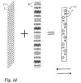
- Fig. 1a shows a multilayer body 1 with a carrier substrate 10 and a film element applied to the carrier substrate comprising an adhesive layer 11, a decorative layer 12 and a transparent layer 13.
- the carrier substrate 10 is preferably a paper substrate with a layer thickness of between 10 ⁇ m and 200 ⁇ m. If the multilayer body 1 is a package, the carrier substrate can also be a (thick) cardboard or plastic substrate. However, it is also possible for the carrier substrate 10 to be a substrate comprising one or more layers.
- the carrier substrate 10 preferably forms the carrier substrate of a value document, preferably a banknote, and is thus optionally also printed with one or more layers on the front and/or back.
- the film element comprising layers 11, 12 and 13 is applied to the carrier substrate 10 in the form of a patch or a strip.
- This film element is, for example, a security thread or security strip, in particular a window security thread or window security strip.
- the film element it is also possible for the film element to completely cover the entire area of the carrier substrate 10.
- the film element comprising layers 11, 12 and 13 is preferably applied to the substrate 10 as a transfer layer of a transfer film, in particular a hot stamping film.
- the film element it is also possible for the film element to be designed as a laminating film or as a security thread and to be applied as such to the carrier substrate 10 or introduced into the carrier substrate 10.
- Layer 11 is an adhesive layer with a layer thickness between 0.5 and 10 ⁇ m, preferably between 1 and 5 ⁇ m.
- the decorative layer 12 is a layer which has a large number of microimages 22 which are arranged according to a microimage grid.
- the decorative layer 12 consists, for example, of a structured, partially provided metal layer, in particular a metal layer with a layer thickness of 10 nm to 5000 nm, which is shaped in a pattern in some areas to form the microimages 22.
- the microimages 22 each show a motif which is formed by the contrast between one or more image areas and one or more background areas 23 which have a different optical appearance.
- the metal of the metal layer is provided as a partial metal layer in the image areas and is not provided in the background areas 23, so that the microimages 22 are shown by the contrast between image areas and background areas 23.
- the adhesive layer 11 is visible through the background areas 23, which thereby serves as a contrasting background layer to the image areas. It has proven advantageous to color the adhesive layer 11 with colored pigments and/or dyes in order to be able to color the background areas 23 as well. This makes it possible to achieve strongly contrasting motifs from, for example, metallic image areas and colored background areas. It is also possible to color the adhesive layer 11 alternatively or additionally with UV-active or IR-active pigments and/or dyes in order to be able to vary the contrast effect between image areas and background areas 23 depending on the lighting conditions.
- the microimages 22 can be formed not only by the decorative layer 12, but by a decorative layer printed directly on the carrier substrate 10 and/or by overlaying the decorative layer 12 with such a layer applied directly to the carrier substrate 10.
- a decorative layer printed directly on the carrier substrate 10 and/or by overlaying the decorative layer 12 with such a layer applied directly to the carrier substrate 10.
- an offset print can have a grid of background colors and image colors that has a frequency spread, whereas the lens grid has a constant frequency.
- offset printing instead of offset printing, another printing process can be used, such as gravure printing, screen printing, pad printing, intaglio printing or even inkjet printing.
- the layer 12 is also possible for the layer 12 to be formed by a colored lacquer layer or a colored photoresist layer or to consist of several (colored) lacquer layers, photoresist layers and/or metal layers, which cause a different optical appearance of the decorative layer 12 in the image areas and background areas and thus form the microimages 22 in the decorative layer 12.
- the decorative layer it is also possible for the decorative layer to have a replication lacquer layer in which an optically active surface relief is molded. The optical contrast between image areas and background areas can be brought about by the surface reliefs being molded either in the image areas or in the background areas or in the image areas and in the Background areas have different surface reliefs molded into the replication lacquer layer.
- the replication lacquer layers and in particular the surfaces of the replication lacquer layers into which the respective surface relief is molded are provided with a reflection-enhancing layer, for example an HRI layer or a metallic layer, preferably made of aluminum, silver, copper, gold, chromium or an alloy with such metals.
- the decorative layer 12 thus has a replication lacquer layer with a molded surface relief and a reflection layer, which is preferably arranged below the replication lacquer layer.
- a diffractive relief structure with a spatial frequency of more than 300 lines/mm, preferably from 500 to 4500 lines/mm, is preferably used as the optically active surface relief.
- the diffractive relief structure is preferably a computer-generated diffraction grating, for example a dot matrix or e-beam hologram, whereby this diffraction grating differs in the image areas and background areas, for example in the azimuth angle, the spatial frequency, the profile shape or the relief depth. It is also possible that an anisotropic or isotropic matt structure, moth-eye structures, asymmetric or symmetrical grating structures, linear grating structures, cross grating structures, hexagonal grating structures, zero-order diffraction structures or combinations of such diffraction structures are used as the surface relief.
- the decorative layer 11 comprises, in addition to or instead of the aforementioned layer, a thin film layer system for producing viewing angle-dependent color shift effects, a liquid crystal layer or a layer comprising optically active pigments, for example UV pigments, liquid crystal pigments or interference layer pigments.
- This layer is preferably structured in such a way that it is provided either in the background areas or in the image areas and thus creates a contrast between image areas and background areas.
- the microimages to have a color gradient or different brightness values in the area of an image area and for the corresponding layers of the decorative layer to be designed accordingly in order to realize this brightness or color gradient accordingly.
- the microimages 22 are - as already mentioned above - arranged according to a one- or two-dimensional microimage grid, whereby the grid width of the microimage grid, ie the respective spacing of adjacent microimages 22, can be constant or can also vary.
- a grid width of 42 of the microimage grid is shown, which is determined by the microimage spacing of the Fig. 1a shown adjacent microimages 22, ie the spacing of their centroids from each other.
- the layer 13 consists of a material that is transparent to the human observer and preferably has a layer thickness of between 5 and 150 ⁇ m.
- Microlenses 21 are molded into the surface of the layer 13 facing away from the layer 12, as shown in Fig. 1a is indicated.
- the microlenses can be spherical microlenses, but also any other lens shape, in particular cylindrical lenses.
- the cylindrical lenses can be spherical, aspherical or diffractive lenses with any phase functions.
- the focal length of the lenses is determined by their radius of curvature.
- the focal length of the microlenses is preferably selected such that the spacing 46 of the microimages 22 from the microlenses 21 is approximately in the range of the focal length of the microlenses 21.
- the relief depth i.e. the distance between the highest and the lowest point of the microlenses, is preferably between 2 and 50 ⁇ m.
- the microlenses 21 can be introduced into the surface of the layer 13, for example, by means of an embossing tool, for example by means of a mechanically acting embossing roller or an embossing stamp, or by means of laser ablation.
- the transparent layer 13 consists, for example, of a lacquer layer, of a plastic film, for example a film made of PET (polyethylene terephthalate), PEN (polyethylene naphthalate) or BOPP (biaxially oriented polypropylene), or of several layers, for example a replication lacquer layer and a transparent carrier film arranged underneath this, for example a PET film.
- the microlenses are preferably molded into the transparent layer 13 by means of UV replication, i.e. by molding the microlens structure into a soft, not yet or only slightly cured replication lacquer layer and then curing the replication lacquer layer with high-energy radiation, preferably UV radiation.
- a lacquer is applied to a transparent layer to produce the microlenses 21 and is provided with a surface corresponding to the microlens grid, for example by a shaping tool or a physical process. It is also possible that the microlenses 21 are diffractive lenses.
- the microlenses 21 are - as already explained above - arranged according to a one- or two-dimensional lens grid, whereby the grid width of the lens grid can be constant or can also vary locally.
- Fig. 1 For example, a grid width of 41, which corresponds to the microlens spacing of the Fig. 1 shown neighboring microlenses, ie the spacing from their centroid.
- the spacing 46 of the microlenses 21 from the microimages 22 is preferably approximately in the range of the focal length of the microlenses 21 and preferably deviates from the focal length of the microlenses 21 by no more than 10%.
- the grid width of the microlens grid along the cutting line of the Fig. 1 The width of the section shown is preferably between 5 and 300 ⁇ m and the grid width of the microimage grid in the direction of the cutting line is preferably between 5 and 300 ⁇ m.
- the design of the grid width of the microimage grid and microlens grid and the mutual alignment of the microlens grid and microimage grid reference is made to the preceding explanations.
- the microlenses 21 are arranged according to a one-dimensional lens grid, as is shown below by way of example with reference to the figures Fig. 1b to Fig. 1e is explained.
- FIG. 1b a plan view of a section of layer 13, in which Fig. 1b the focal point lines of the microlenses 21 formed in the form of cylindrical lenses are indicated by lines.
- the microlenses 21 are arranged according to a one-dimensional microlens grid, which is a Coordinate system with the axes 50 and 51.
- the axis 50 of the coordinate system is oriented parallel to the transverse axis of the multilayer body 1 and parallel to the focal lines of the microlenses 21 and the coordinate axis 51 is oriented perpendicular to the coordinate axis 50.
- the microlenses 21 preferably have a length of more than 1 mm and the distance between adjacent microlenses 21, the grid width 41, is less than 300 ⁇ m, preferably between 10 and 200 ⁇ m.
- the centroid lines of the microimages 22 are preferably oriented substantially parallel or parallel to the coordinate axis 50 and the grid widths of the microimage grid and the microlens grid differ from one another, in particular between 0.5 and 5%.
- Fig. 1c shows a top view of layer 3, where - as in Fig. 1b - the focal point lines of the microlenses 21 are marked by corresponding lines.
- the microlenses 21 are formed by cylindrical lenses which are arranged according to a one-dimensional microlens grid with a grid width 41 between 10 ⁇ m and 300 ⁇ m, here 35 ⁇ m.
- the focal length or the focus length of the microlenses is between 10 ⁇ m and 500 ⁇ m.
- the focal point lines of the microlenses 21 are rotated at an angle of 45° relative to the longitudinal axis of the multilayer body 1 and are arranged essentially parallel to one another.
- the coordinate axis 51 illustrates the longitudinal direction of the multilayer body 1 and the coordinate axis 50 illustrates the transverse direction of the multilayer body 1, which is preferably a strip-shaped or thread-shaped security element.
- the microimages 22 are arranged according to a microimage grid which - as described above - is arranged rotated relative to the microlens grid (in particular rotated by 45°) or, as described above, differs from it in the grid width.
- Fig. 1d illustrated optical appearance 60 in which foreground elements 61 describe a left-right movement when tilting the multilayer body 1 in the horizontal axis and a left-right movement when tilting the multilayer body 1 about the vertical axis.
- FIG. 1e Another embodiment is Fig. 1e clarified.
- Fig. 1e also shows a top view of the layer 13, whereby the focal point lines of the microlenses 21 are also indicated by lines.
- the microlenses 21 are formed by concentrically arranged cylindrical lenses, each of which has a circular shape and is spaced apart from one another by a grid width 41 - as in Fig. 1d indicated - are arranged.
- the microlenses 21 are arranged according to a geometrically transformed one-dimensional microlens grid and thus, for example, the focal lines of the microlenses in the plane spanned by the coordinate axes 50 and 51 each have a serpentine shape.
- FIG. 1f shows a section of the multilayer body 1 with a microlens 21 and an associated microimage 22.
- the microlens 21 is a cylindrical lens with a radius 47 and a maximum structure height 44.
- the micrographs 22 are not - as in Fig. 1a shown - arranged in a flat plane, but rather arranged on a curved surface of the layer 13 in the area of the respective microimage 22.
- a surface structure is replicated in the layer 13 both in the top and in the bottom, whereby the surface structures provided in the area of the microimages 22 preferably have a lens-shaped shape - as shown in Figure 1f
- the microstructure molded into the layer 13 in the area of the microimages 22 has a similar shape to the microlens 21 and thus forms a curvature in the form of a section of a cylinder surface, as shown in Fig. 1f is shown.
- r is the radius of the microlens 21 and x i is the position of the image with respect to the surface normal of the layer 13, i.e. the dimension 46.
- x i is the position of the image with respect to the surface normal of the layer 13, i.e. the dimension 46.
- the curvature for the microimage 22 is therefore to be selected such that the deepest point of the microimage 22 is 150 ⁇ m away from the top side facing away from the microimage, i.e. the dimension 46 is 150 ⁇ m. and that in the edge region of the image the microimage is arranged 122.75 ⁇ m away from the top layer 13.
- Fig. 2 shows a multilayer body 2, which is improved and modified compared to the multilayer body 1 as described below:
- the multilayer body 2 comprises the carrier substrate 10 and the film element with the layers 11, 12 and 13.
- the layer 13 is like the layer 13 according to Fig. 1a to Fig. 1f formed with the difference that the microlenses 21 in the area 31 are not, as in the embodiment according to Fig. 1 , follow one another immediately, but that between the microlenses 21 "flat" areas are provided, which are not part of a microlens and do not contribute anything to the deflection function of the microlenses 21.
- the lenses point in the direction of the cutting line of the Fig.
- the 2 illustrated section has a dimension 43 which is at least 30%, in particular more than 50%, smaller than the respective grid width of the microlens grid along the cutting line, ie the dimension 43 is ⁇ 0.5 grid width 41.
- the microlenses 21 have a maximum structure height, ie dimension 44, which is at least 25%, in particular at least 50% of the dimension 43 of the microlenses.
- the distance between the base plane of the microlenses 21 and the decorative layer 12 is selected approximately (deviation ⁇ 10 %) so that it corresponds to the focal length of the microlenses 21.
- the maximum structure height of the microlenses 21 also decreases accordingly when the focal length of the microlenses 21 is reduced, so that a particularly thin design of the multilayer body 2 can be achieved by these two effects.
- the decorative layer 12 is like the decorative layer 12 according to Fig. 1a to Fig. 1f trained, whereby in Fig. 2 an embodiment of the decorative layer 12 is shown, in which the decorative layer consists of a transparent replication lacquer layer 122 and a full-surface metal layer 121, wherein in the areas forming the image areas of the microimages 22 a diffractive relief structure 123 is molded into the surface of the replication lacquer layer 122 and in the background areas 23 such a relief structure is not molded, ie these areas are designed as mirror areas. It is also worth mentioning here that in the embodiment according to Fig. 2 the dimension 45 of the microimages 21 in a first spatial direction, here in the direction of the cutting line of the Fig. 2 shown section, more than 50%, in particular more than 100%, of the dimension 43 of adjacent microlenses 21 in the first spatial direction. This achieves the advantages already set out above.
- the dimension 43 is preferably between 5 ⁇ m and 100 ⁇ m
- the maximum structure height 44 of the microlenses 21 is between 3 ⁇ m and 50 ⁇ m
- the dimension 45 of the microimages 22 is preferably between 3 ⁇ m and 50 ⁇ m.
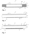
- Fig. 3 shows a multilayer body 3, which represents a banknote.
- the multilayer body 3 has in the area 31 the carrier layer 10, the adhesive layer 11, the decorative layer 12 with the microimages 22 and the transparent layer 13 with the microlenses 21.
- the transparent layer 13 can be integrally linked to the carrier layer 10, which means that the microlenses 21 can also be introduced directly as a surface relief into the carrier layer 10 without using a separate layer 13, preferably embossed. If a separate layer 13 is applied to the carrier layer 10, this can advantageously be a radiation-curing lacquer, into which the microlenses 21 are embossed by means of an embossing roller and the lacquer is then cured, for example with UV radiation.
- the carrier substrate 10 is the carrier substrate of the banknote.
- the carrier substrate 10 is transparent. If the carrier substrate 10 consists, for example, of a plastic film or of a multilayer laminate of several plastic layers, these plastic layers are transparent to the human observer in the area 32. If it is a paper substrate, the carrier substrate 10 preferably has a window-shaped opening in the area 32, which is then covered on both sides by the Fig. 3 shown layers. Outside the area 32, the carrier substrate 10 is preferably opaque, ie printed with corresponding opaque layers or provided with a correspondingly colored layer.
- a film element with the layers 11 and 13 is now applied to the front of the carrier substrate 10 and a film element with the layers 11, 12 and a layer 15 is applied to the back.
- the layer 15 is an optional protective lacquer layer.
- the application of these film elements to the carrier substrate 10 can be carried out by means of one of the methods described above, for example by transferring the transfer layer of a transfer film or laminating a laminating film onto the carrier substrate 10.
- the film elements applied to the carrier substrate 10 are particularly thin, since the carrier substrate is advantageously used here as an additional spacer layer for the formation of the first optically variable effect and thus the layer thickness of the layer 13 can be chosen to be particularly thin.
- the decorative layer 12 is not part of a film element applied to the carrier substrate 10, but that the decorative layer 12 is applied directly to the carrier substrate 10 by means of a printing process.
- the multilayer body 3 achieves the advantages already described above.
- Fig. 4 shows a multilayer body 4, which is a modification of the multilayer body 3 according to Fig. 3
- the multilayer body 4 comprises the carrier substrate 10, the adhesive layers 11, the decorative layer 12 with the microimages 22, the transparent layer 13 with the microlenses 21 and the protective lacquer layer 15.
- the multilayer body 4 is like the multilayer body 3 according to Fig. 3 designed with the difference that the carrier substrate 10 is completely transparent and that above the transparent layer 13 a replication lacquer layer 14 is arranged, the refractive index of which differs from the refractive index of the material of the layer 13
- the film element applied to the front side of the carrier substrate 10 is preferably produced as follows:
- the replication lacquer layer 14 is applied to an optional carrier layer and release layer (in the case of a transfer film) and a surface relief corresponding to the microlens grid with the microlenses 21 is embossed into the replication lacquer layer 14. This surface relief is then filled with another lacquer layer, layer 13, and then the other layers, in particular the adhesive layer 11, are applied.
- the film element is then applied to the carrier substrate 10.
- the design according to Fig. 4 has the further advantage that the surface structure of the microlenses 21 is not molded into the front side, ie the upper surface of the multilayer body, and thus cannot be reproduced by means of a contact copy. Furthermore, the microlenses are protected by the layer 14 from mechanical wear, for example scratches, so that the durability of the multilayer body is improved.
- Fig. 5 shows a multilayer body 5, which is a further variation of the multilayer body 3 and the multilayer body 4 according to Fig. 3 or Fig. 4
- the multilayer body 5 comprises the carrier substrate 10, the layer 11, the decorative layer 12 with the microimages 22, the layer 13 with the microlenses 21 and the layer 14.
- the multilayer body 5 is like the multilayer body 4 according to Fig. 4 formed with the difference that the film element applied to the front side of the carrier substrate 10 further comprises a security element 16, the film element applied to the underside of the film body comprises a security element 18 and a cover layer 17, and the underside of the carrier substrate 10 is provided with an imprint 9.
- the cover layer 17 is formed by an opaque layer which decouples the optical effect of the decorative layer 12 and the optical effect of the security element 18 from one another. This layer could also be omitted.
- the security elements 16 and 18 each consist of one or more layers selected from the group of replication lacquer layer with molded optically active surface relief, reflection layer, metal layer, colored lacquer layer, layer with optically active pigments, liquid crystal layer, volume hologram layer and thin film layer system.
- the security element 18 preferably forms a second optically variable information which differs from the first optically variable information generated in the area 31 by the layers 13, 15 and 12. When viewed from the front, the optically variable effect generated by the layers 12 and 13 is visible in the area 31 and when viewed from the back, the optically variable effect generated by the security element 18 is visible.
- the security element 16 can be designed like the security element 18. When viewed from the front, the security element 16 generates a corresponding, preferably optically variable impression in an area 33 in which it is provided in the film element applied to the front of the carrier substrate 10. Furthermore, the security feature 16 is arranged in precise registration with the security element 18. When viewed in transmitted light, the security elements 16 and 18 complement each other to form a further security element, for example forming complementary representations which, when viewed in transmitted light, combine to form an overall motif, for example. Part of this overall motif is also the print 19, which is also arranged in precise registration with the security elements 16 and 18.
- the optically variable effect generated by the security element 16 is preferably visible in the area 33 and, when viewed in transmitted light, the "watermark effect" provided by the print 19, the security element 16 and the security element 18 is visible in the areas 31, 33 and 34, which is determined by the precise arrangement of the layers of the security elements 16 and 18 and the print 19 in relation to one another.
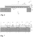
- Fig. 6 shows a multilayer body 6 with the carrier substrate 10, the adhesive layer 11, the decorative layer 12 with the microimages 22 arranged in the area 31 and the transparent layer 13 with the microlenses 21 arranged in the area 31.
- the aforementioned layers are like the layers of the same name of the multilayer body 1 and 2 according to Fig. 1a to Fig. 2 formed with the difference that in the area 31 a window-shaped opening is additionally provided in the carrier substrate 10.
- a translucent layer 20 is arranged between the decorative layer 12 and the transparent layer 13.
- the translucent layer 20 preferably consists of a colored lacquer layer and preferably has a layer thickness between 1 ⁇ m and 30 ⁇ m.
- the decorative layer is designed in such a way that the transparency of the decorative layer differs in the image areas and the background areas, for example the background areas are completely transparent and the image areas are opaque.
- the above-described design of the multilayer body 6 ensures that the optically variable effect generated in the region 31 by the layers 12 and 13 only comes into effect when viewed in transmitted light and is cancelled out when viewed in incident light by the translucent layer 20 and the scattering effect caused by it.
- Fig. 7 shows a multilayer body 7 with the carrier substrate 10, the adhesive layer 11, the decorative layer 12 and the transparent layer 13.
- the decorative layer 12 has zones 34 and 33 in the area 31.
- the decorative layer 12 is as described above with respect to Fig. 1 or Fig. 2 described.
- the decorative layer 12 has a replication lacquer layer with an optically active surface structure 24, which is intended to generate further optically variable information that differs from the first optically variable information generated in the zones 34.
- a lacquer layer 30 is printed on the surface of the transparent layer 13.
- the lacquer layer 30 is a lacquer layer made of a material whose refractive index differs by no more than 0.3 from the refractive index of the material of the transparent layer. This has the effect that the optical effect of the microlenses 21 in the zones 33 is cancelled out for the human observer and thus only the optically variable effect generated by the optically active surface structure 24 is visible to the human observer in the zones 33.
- Fig. 8 shows a multilayer body 8, with the carrier substrate 10, the adhesive layer 11, the decorative layer 12 and the transparent layer 13. These layers are, except for the following differences, like the layers of the same name according to Fig. 7 constructed: Instead of extinguishing the optical effect of the microlenses 21 in the zones 33, the variant shown here is that the layer 13 is not provided in the area of the zones 33. The layer 13 is thus partially designed so that the layer 13 with the microlenses 21 is not provided in the zones 33 or in part of the zones 33. As a result, the optically variable effect of the optically active surface structures 24 is particularly brilliant in these areas 33 because there is no or only a partial covering of the optically variable effect by other layers.
- microlenses it is possible to only partially mold the microlenses into the layer 13. As in Fig. 8 As shown, in zones 33 the microlenses are not molded and, for example, as in Fig. 8 shown, replaced by a flat surface profile or a largely smooth or flat surface profile without optical distortion function.
- zones 34 are areas with differently formed and/or oriented microimage grids and microstructure grids, as previously described in Fig. 1b, 1c , 1d , 1e and zones 33 for generating further optically variable information are arranged adjacent to one another.
- adjacent means that adjacent zones have a common boundary line or boundary zone.
- adjacent zones In order to compensate for existing manufacturing tolerances in the positions of the respective zones, it is possible for adjacent zones to overlap slightly with one another in an overlapping area designed as a boundary zone, with the boundary zone preferably being slightly wider than the maximum manufacturing tolerance, for example between 10 ⁇ m and 5 mm wide.
- Boundary zones can be provided on the entire circumference of a zone or only on part of the circumference, for example only in the area of a boundary line to an adjacent zone.
- Such manufacturing tolerances can occur, for example, when applying the individual layers in different production steps, preferably in a roll-to-roll process for the microimage grids and/or the microstructure grids, which can result in a slight offset in the relative arrangement of the layers to one another.
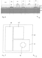
- Fig. 9 shows a multilayer body 9 with the areas 35, 36 and areas 37 and 38.
- the microimage grid and the microstructure grid differ from each other, in particular in one of the parameters selected from the group of microimage spacing, microstructure spacing and alignment of the coordinate axis, which are spanned by the microstructure grid and the microimage grid.
- the microimage grid or the microstructure grid can also be identical in individual areas 35 to 38, but out of phase with the other areas.
- zones 21, 22 and 23 are arranged according to a microstructure grid and a microimage grid in which the difference between the microimage distance and the microstructure distance is positive in area 134 and negative in area 135. This causes, for example, an opposite movement of the motif that appears when tilting in areas 37 and 38.
- zones 34 with optically variable information with adjacent zones 33 with contrasting optically variable information is possible, for example as individual motifs within an overall motif, so that the zones 33 can serve as a contrasting optical reference for the optically variable information in the zones 34.
- these can be movement effects in the areas 35 to 38 and a surrounding area 39 without a movement effect or a movement effect in the area 38 with a surrounding or adjacent area 37 without a movement effect, for example with a hologram and/or with optically variable pigments or opposing movement effects in the areas 35 to 38.
- Contrasting optically variable information can also be generated, for example, by providing a microstructure grid over a microimage grid or other optically variable motifs in one or more areas 35 to 38 and in other areas 35 to 38 that are directly or indirectly adjacent to it, the microstructure grid is either erased, for example with a lacquer layer with a similar refractive index, or is not provided. It is also possible to provide optically variable information in the areas 35 to 38 adjacent to optically static information, for example single-colored areas or multi-coloured, non-optically variable motifs, adjacent to each other.
Landscapes
- Physics & Mathematics (AREA)
- Optics & Photonics (AREA)
- General Physics & Mathematics (AREA)
- Engineering & Computer Science (AREA)
- Manufacturing & Machinery (AREA)
- Business, Economics & Management (AREA)
- Finance (AREA)
- Accounting & Taxation (AREA)
- Credit Cards Or The Like (AREA)
- Printing Methods (AREA)
- Laminated Bodies (AREA)
- Diffracting Gratings Or Hologram Optical Elements (AREA)
- Optical Elements Other Than Lenses (AREA)
Applications Claiming Priority (3)
| Application Number | Priority Date | Filing Date | Title |
|---|---|---|---|
| DE102009040975A DE102009040975A1 (de) | 2009-09-11 | 2009-09-11 | Mehrschichtkörper |
| PCT/EP2010/005552 WO2011029602A2 (de) | 2009-09-11 | 2010-09-09 | Mehrschichtkörper |
| EP10757030.1A EP2475529B8 (de) | 2009-09-11 | 2010-09-09 | Mehrschichtkörper |
Related Parent Applications (2)
| Application Number | Title | Priority Date | Filing Date |
|---|---|---|---|
| EP10757030.1A Division EP2475529B8 (de) | 2009-09-11 | 2010-09-09 | Mehrschichtkörper |
| EP10757030.1A Division-Into EP2475529B8 (de) | 2009-09-11 | 2010-09-09 | Mehrschichtkörper |
Publications (3)
| Publication Number | Publication Date |
|---|---|
| EP3581395A2 EP3581395A2 (de) | 2019-12-18 |
| EP3581395A3 EP3581395A3 (de) | 2020-05-20 |
| EP3581395B1 true EP3581395B1 (de) | 2024-10-23 |
Family
ID=43125496
Family Applications (2)
| Application Number | Title | Priority Date | Filing Date |
|---|---|---|---|
| EP19182346.7A Active EP3581395B1 (de) | 2009-09-11 | 2010-09-09 | Mehrschichtkörper |
| EP10757030.1A Active EP2475529B8 (de) | 2009-09-11 | 2010-09-09 | Mehrschichtkörper |
Family Applications After (1)
| Application Number | Title | Priority Date | Filing Date |
|---|---|---|---|
| EP10757030.1A Active EP2475529B8 (de) | 2009-09-11 | 2010-09-09 | Mehrschichtkörper |
Country Status (11)
Families Citing this family (41)
| Publication number | Priority date | Publication date | Assignee | Title |
|---|---|---|---|---|
| GB201003397D0 (en) * | 2010-03-01 | 2010-04-14 | Rue De Int Ltd | Moire magnification security device |
| EP2703887A4 (en) * | 2011-04-22 | 2014-12-03 | Grapac Japan Co Inc | PICTURE DISPLAY AND PICTURE BODIES |
| FR2979735B1 (fr) * | 2011-09-02 | 2014-05-23 | Arjowiggins Security | Structure de securite comportant un vernis transparent, et procede associe. |
| RU2605372C9 (ru) | 2011-09-26 | 2017-05-24 | Крейн Секьюрити Текнолоджис, Инк. | Способ изготовления композитной ленты и защитные средства, выполненные из композитной ленты |
| JP5906653B2 (ja) * | 2011-10-11 | 2016-04-20 | 凸版印刷株式会社 | 表示体および物品 |
| DE102011121588A1 (de) | 2011-12-20 | 2013-06-20 | Giesecke & Devrient Gmbh | Sicherheitselement für Sicherheitspapiere, Wertdokumente oder dergleichen |
| GB201208137D0 (en) * | 2012-05-10 | 2012-06-20 | Rue De Int Ltd | Security devices and methods of manufacture therefor |
| DE102012014414A1 (de) | 2012-07-20 | 2014-01-23 | Giesecke & Devrient Gmbh | Sicherheitselement für Sicherheitspapiere, Wertdokumente oder dergleichen |
| KR101960402B1 (ko) * | 2012-08-03 | 2019-03-20 | 쑤저우 에스브이쥐 옵트로닉스 테크놀러지 컴퍼니 리미티드 | 컬러 다이나믹 증폭 보안 필름 |
| KR102219805B1 (ko) | 2013-03-12 | 2021-02-24 | 도판 인사츠 가부시키가이샤 | 표시체 |
| RU2516474C1 (ru) * | 2013-04-09 | 2014-05-20 | Федеральное Государственное Унитарное Предприятие "Гознак" (Фгуп "Гознак") | Слоистое изделие на бумажной или полимерной основе (варианты) и способ его изготовления |
| KR101341072B1 (ko) * | 2013-09-04 | 2013-12-19 | 안재광 | 복수의 나노 구조물 및 입체 렌즈를 이용한 진품 확인용 라벨 |
| GB2520321A (en) * | 2013-11-18 | 2015-05-20 | Melexis Technologies Nv | Infrared sensor with limitation aperture |
| WO2015085438A1 (en) * | 2013-12-09 | 2015-06-18 | Orell Füssli Sicherheitsdruck Ag | Security document with stress compensated foil element |
| DE102014004941A1 (de) | 2014-04-04 | 2015-10-08 | Giesecke & Devrient Gmbh | Sicherheitselement für Sicherheitspapiere, Wertdokumente oder dergleichen |
| DE102015210982A1 (de) * | 2015-06-15 | 2016-12-15 | Tesa Scribos Gmbh | Sicherheitsetikett mit Kippeffekt |
| MA42904A (fr) | 2015-07-10 | 2018-05-16 | De La Rue Int Ltd | Procédés de fabrication de documents de sécurité et de dispositifs de sécurité |
| CN105479974B (zh) * | 2015-12-01 | 2018-07-13 | 中钞特种防伪科技有限公司 | 一种光学防伪元件及使用该光学防伪元件的光学防伪产品 |
| DE102015016751A1 (de) | 2015-12-23 | 2017-06-29 | Giesecke & Devrient Gmbh | Sicherheitselement für Sicherheitspapiere, Wertdokumente oder dergleichen |
| GB2549779B (en) * | 2016-04-29 | 2020-05-20 | De La Rue Int Ltd | Security elements and methods of manufacture thereof |
| GB2549780B (en) * | 2016-04-29 | 2019-11-27 | De La Rue Int Ltd | Methods of manufacturing lens transfer structures |
| CN106018343B (zh) * | 2016-06-15 | 2019-02-12 | 暨南大学 | 一种微透镜或微透镜阵列成像检测板 |
| DE102016109193A1 (de) * | 2016-05-19 | 2017-11-23 | Ovd Kinegram Ag | Verfahren zur Herstellung von Sicherheitselementen mit einem Lenticular Flip |
| GB201612290D0 (en) * | 2016-07-15 | 2016-08-31 | La Rue Int De Ltd | Methods of manufacturing a secuirty device |
| WO2018025775A1 (ja) | 2016-08-01 | 2018-02-08 | 凸版印刷株式会社 | 印刷物及び印刷物の製造方法 |
| GB2562198B (en) * | 2017-02-03 | 2021-05-05 | De La Rue Int Ltd | Method of forming a security document |
| GB2562699B (en) * | 2017-02-03 | 2020-07-22 | De La Rue Int Ltd | Method of forming a security device |
| GB2563187B (en) | 2017-02-03 | 2020-07-22 | De La Rue Int Ltd | Method of forming a security sheet substrate |
| DE102017003281A1 (de) * | 2017-04-04 | 2018-10-04 | Giesecke+Devrient Currency Technology Gmbh | Sicherheitselement mit Reliefstruktur und Herstellungsverfahren hierfür |
| EP3401114A1 (en) * | 2017-05-12 | 2018-11-14 | KBA-NotaSys SA | Security element or document and process of producing the same |
| DE102017130588A1 (de) * | 2017-12-19 | 2019-06-19 | Giesecke+Devrient Currency Technology Gmbh | Wertdokument |
| DE102018103236A1 (de) | 2018-02-14 | 2019-08-14 | Leonhard Kurz Stiftung & Co. Kg | Sicherheitselement und Verfahren zur Herstellung eines Sicherheitselements |
| DE102018005697A1 (de) * | 2018-07-19 | 2020-01-23 | Giesecke+Devrient Currency Technology Gmbh | Sicherheitselement mit Linsenrasterbild |
| EP3869274A4 (en) * | 2018-10-16 | 2021-11-24 | Toppan Printing Co., Ltd. | INTEGRATED THREE-DIMENSIONAL DISPLAY BODY AND IDENTIFICATION INFORMATION RECORDING PROCESS |
| WO2020085332A1 (ja) * | 2018-10-22 | 2020-04-30 | 凸版印刷株式会社 | 光学表示体、ページ対、製品、印刷製品、パスポート、カード、紙幣、ラベル、タグ、およびチケット |
| GB2580069B (en) * | 2018-12-20 | 2022-06-15 | De La Rue Int Ltd | Security documents and methods of manufacture thereof |
| GB201913913D0 (en) * | 2019-09-26 | 2019-11-13 | Optrical Ltd | Improvements in and relating to security devices |
| US11392810B2 (en) * | 2019-12-12 | 2022-07-19 | Thales Dis France Sa | Covert floating image |
| DE102020113144A1 (de) * | 2020-05-14 | 2021-11-18 | Leonhard Kurz Stiftung & Co. Kg | Verfahren zum Herstellen eines Mehrschichtkörpers sowie ein Mehrschichtkörper |
| DE102020114967A1 (de) | 2020-06-05 | 2021-12-09 | Leonhard Kurz Stiftung & Co. Kg | Verfahren zum Herstellen eines Mehrschichtkörpers sowie einen Mehrschichtkörper |
| DE102022131373A1 (de) * | 2022-11-28 | 2024-05-29 | Leonhard Kurz Stiftung & Co. Kg | Verfahren zur Herstellung eines Mehrschichtkörpers sowie Mehrschichtkörper |
Family Cites Families (23)
| Publication number | Priority date | Publication date | Assignee | Title |
|---|---|---|---|---|
| GB236249A (en) | 1924-02-29 | 1925-06-29 | Edward Lynton Vicars | Improvements in or relating to wafer & like baking plates |
| DE3609090A1 (de) | 1986-03-18 | 1987-09-24 | Gao Ges Automation Org | Wertpapier mit darin eingelagertem sicherheitsfaden und verfahren zur herstellung derselben |
| US5323384A (en) | 1992-12-23 | 1994-06-21 | Motorola, Inc. | Method for establishing communication between tasks of a limited number of repeaters in a communication system |
| GB9309673D0 (en) | 1993-05-11 | 1993-06-23 | De La Rue Holographics Ltd | Security device |
| ES2223197T3 (es) | 1999-11-29 | 2005-02-16 | Ecole Polytechnique Federale De Lausanne (Epfl) | Nuevos metodos y aparatos para la autenticacion de documentos que emplean el perfil de intensidad de patrones muare. |
| US7336422B2 (en) * | 2000-02-22 | 2008-02-26 | 3M Innovative Properties Company | Sheeting with composite image that floats |
| FR2808478B1 (fr) * | 2000-05-03 | 2002-07-19 | Hologram Ind | Moyen de securisation d'un substrat |
| EP2258560A3 (en) * | 2003-11-21 | 2011-04-13 | Visual Physics, LLC | Micro-optic security and image presentation system |
| WO2005106601A2 (en) * | 2004-04-30 | 2005-11-10 | De La Rue International Limited | Arrays of microlenses and arrays of microimages on transparent security substrates |
| RU2381907C2 (ru) * | 2004-08-12 | 2010-02-20 | Гизеке Унд Девриент Гмбх | Элемент защиты, имеющий основу |
| DE102005007749A1 (de) | 2005-02-18 | 2006-08-31 | Giesecke & Devrient Gmbh | Sicherheitselement und Verfahren zu seiner Herstellung |
| DE102005028162A1 (de) * | 2005-02-18 | 2006-12-28 | Giesecke & Devrient Gmbh | Sicherheitselement und Verfahren zu seiner Herstellung |
| EP2365376B1 (en) * | 2005-05-18 | 2015-10-07 | Visual Physics, LLC | Image presentation and micro-optic security system |
| DE102005062132A1 (de) * | 2005-12-23 | 2007-07-05 | Giesecke & Devrient Gmbh | Sicherheitselement |
| DE102006005000B4 (de) | 2006-02-01 | 2016-05-04 | Ovd Kinegram Ag | Mehrschichtkörper mit Mikrolinsen-Anordnung |
| DE102006029536B4 (de) * | 2006-06-26 | 2011-05-05 | Ovd Kinegram Ag | Mehrschichtkörper mit Mikrolinsen sowie Verfahren zu seiner Herstellung |
| DE102006032660A1 (de) * | 2006-07-13 | 2008-01-17 | Ovd Kinegram Ag | Mehrschichtkörper mit Mikrooptik |
| JP2008052202A (ja) * | 2006-08-28 | 2008-03-06 | Tanaka Sangyo Kk | レンズ状シート |
| GB2482077B (en) | 2006-09-15 | 2012-02-29 | Securency Int Pty Ltd | Improvements in security documents |
| DE102007005414A1 (de) * | 2007-01-30 | 2008-08-07 | Ovd Kinegram Ag | Sicherheitselement zur Sicherung von Wertdokumenten |
| DE102007007914A1 (de) * | 2007-02-14 | 2008-08-21 | Giesecke & Devrient Gmbh | Prägelack für mikrooptische Sicherheitselemente |
| DE102007029203A1 (de) * | 2007-06-25 | 2009-01-08 | Giesecke & Devrient Gmbh | Sicherheitselement |
| DE102007049512B4 (de) * | 2007-10-15 | 2010-09-30 | Ovd Kinegram Ag | Mehrschichtkörper sowie Verfahren zur Herstellung eines Mehrschichtkörpers |
-
2009
- 2009-09-11 DE DE102009040975A patent/DE102009040975A1/de active Pending
-
2010
- 2010-09-09 CA CA2772149A patent/CA2772149C/en active Active
- 2010-09-09 RU RU2012114125/12A patent/RU2549069C2/ru active
- 2010-09-09 CN CN201080040873.5A patent/CN102497995B/zh active Active
- 2010-09-09 WO PCT/EP2010/005552 patent/WO2011029602A2/de active Application Filing
- 2010-09-09 AU AU2010294467A patent/AU2010294467C1/en active Active
- 2010-09-09 JP JP2012528274A patent/JP5700580B2/ja active Active
- 2010-09-09 MX MX2012002897A patent/MX2012002897A/es active IP Right Grant
- 2010-09-09 EP EP19182346.7A patent/EP3581395B1/de active Active
- 2010-09-09 US US13/395,251 patent/US9994062B2/en active Active
- 2010-09-09 EP EP10757030.1A patent/EP2475529B8/de active Active
- 2010-09-10 TW TW099130573A patent/TWI535579B/zh active
-
2018
- 2018-05-11 US US15/977,621 patent/US11077700B2/en active Active
Also Published As
| Publication number | Publication date |
|---|---|
| CN102497995B (zh) | 2015-09-09 |
| EP2475529B1 (de) | 2019-06-26 |
| RU2549069C2 (ru) | 2015-04-20 |
| DE102009040975A1 (de) | 2011-03-24 |
| CN102497995A (zh) | 2012-06-13 |
| CA2772149C (en) | 2017-09-05 |
| AU2010294467B2 (en) | 2014-09-04 |
| MX2012002897A (es) | 2012-04-02 |
| EP2475529A2 (de) | 2012-07-18 |
| AU2010294467C1 (en) | 2017-03-09 |
| US9994062B2 (en) | 2018-06-12 |
| EP3581395A3 (de) | 2020-05-20 |
| EP3581395A2 (de) | 2019-12-18 |
| WO2011029602A2 (de) | 2011-03-17 |
| AU2010294467A1 (en) | 2012-03-22 |
| CA2772149A1 (en) | 2011-03-17 |
| US11077700B2 (en) | 2021-08-03 |
| US20120193905A1 (en) | 2012-08-02 |
| JP2013504451A (ja) | 2013-02-07 |
| WO2011029602A3 (de) | 2011-05-05 |
| RU2012114125A (ru) | 2013-10-20 |
| EP2475529B8 (de) | 2019-09-11 |
| TWI535579B (zh) | 2016-06-01 |
| US20180264869A1 (en) | 2018-09-20 |
| JP5700580B2 (ja) | 2015-04-15 |
| TW201109193A (en) | 2011-03-16 |
Similar Documents
| Publication | Publication Date | Title |
|---|---|---|
| EP3581395B1 (de) | Mehrschichtkörper | |
| EP2451650B2 (de) | Mehrschichtkörper | |
| EP1853763B1 (de) | Sicherheitselement und verfahren zu seiner herstellung | |
| EP1800271B1 (de) | Sicherheitsdokument | |
| EP2635444B1 (de) | Sicherheitselement und verfahren zur herstellung eines sicherheitselements | |
| EP1747100B1 (de) | Sicherheitselement in form eines mehrschichtigen folienkörpers | |
| EP2091756B1 (de) | Durchsichtssicherheitselement mit mikrostrukturen | |
| EP2040934B2 (de) | Sicherheitselement | |
| EP3216620B1 (de) | Sicherheitselement, wertdokument mit einem solchen sicherheitselement sowie herstellungsverfahren eines sicherheitselementes | |
| EP2200841B1 (de) | Mehrschichtkörper sowie verfahren zur herstellung eines mehrschichtkörpers | |
| EP2853411B1 (de) | Sicherheitselement mit Linsenrasterbild | |
| EP2897812B1 (de) | Sicherheitselement mit darstellungsanordnung | |
| EP2889152B1 (de) | Sicherheitselement zur Darstellung zumindest einer optisch variablen Information | |
| EP2385902B1 (de) | Sicherheitselement und sicherheitspapier | |
| WO2017097430A1 (de) | Sicherheitselement mit linsenrasterbild | |
| WO2017028954A1 (de) | Wertdokument | |
| EP2768660B1 (de) | Verfahren zum herstellen von mikrohohlspiegeln | |
| AT526897A2 (de) | Mikrooptische Vorrichtung zum Erzeugen eines vergrößerten Bildes | |
| EP4384401A1 (de) | Verfahren zur herstellung eines sicherheitsmerkmals, sicherheitsmerkmal für einen datenträger, datenträger und laminierblech |
Legal Events
| Date | Code | Title | Description |
|---|---|---|---|
| PUAI | Public reference made under article 153(3) epc to a published international application that has entered the european phase |
Free format text: ORIGINAL CODE: 0009012 |
|
| STAA | Information on the status of an ep patent application or granted ep patent |
Free format text: STATUS: REQUEST FOR EXAMINATION WAS MADE |
|
| 17P | Request for examination filed |
Effective date: 20190625 |
|
| AC | Divisional application: reference to earlier application |
Ref document number: 2475529 Country of ref document: EP Kind code of ref document: P |
|
| AK | Designated contracting states |
Kind code of ref document: A2 Designated state(s): AL AT BE BG CH CY CZ DE DK EE ES FI FR GB GR HR HU IE IS IT LI LT LU LV MC MK MT NL NO PL PT RO SE SI SK SM TR |
|
| PUAL | Search report despatched |
Free format text: ORIGINAL CODE: 0009013 |
|
| AK | Designated contracting states |
Kind code of ref document: A3 Designated state(s): AL AT BE BG CH CY CZ DE DK EE ES FI FR GB GR HR HU IE IS IT LI LT LU LV MC MK MT NL NO PL PT RO SE SI SK SM TR |
|
| RIC1 | Information provided on ipc code assigned before grant |
Ipc: B42D 25/45 20140101ALI20200415BHEP Ipc: B42D 25/36 20140101ALI20200415BHEP Ipc: G07D 7/00 20160101ALI20200415BHEP Ipc: B42D 15/00 20060101AFI20200415BHEP Ipc: B42D 25/328 20140101ALI20200415BHEP Ipc: B42D 25/324 20140101ALI20200415BHEP Ipc: G02B 3/00 20060101ALI20200415BHEP Ipc: B42D 25/29 20140101ALI20200415BHEP Ipc: G02B 27/60 20060101ALI20200415BHEP Ipc: B42D 25/351 20140101ALI20200415BHEP |
|
| STAA | Information on the status of an ep patent application or granted ep patent |
Free format text: STATUS: EXAMINATION IS IN PROGRESS |
|
| 17Q | First examination report despatched |
Effective date: 20220527 |
|
| REG | Reference to a national code |
Ref country code: DE Ref legal event code: R079 Ref document number: 502010017101 Country of ref document: DE Free format text: PREVIOUS MAIN CLASS: B42D0015000000 Ipc: B42D0025290000 Ref country code: DE Ref legal event code: R079 Free format text: PREVIOUS MAIN CLASS: B42D0015000000 Ipc: B42D0025290000 |
|
| GRAP | Despatch of communication of intention to grant a patent |
Free format text: ORIGINAL CODE: EPIDOSNIGR1 |
|
| STAA | Information on the status of an ep patent application or granted ep patent |
Free format text: STATUS: GRANT OF PATENT IS INTENDED |
|
| RIC1 | Information provided on ipc code assigned before grant |
Ipc: G02B 3/00 20060101ALI20240725BHEP Ipc: B42D 25/45 20140101ALI20240725BHEP Ipc: B42D 25/36 20140101ALI20240725BHEP Ipc: B42D 25/351 20140101ALI20240725BHEP Ipc: B42D 25/328 20140101ALI20240725BHEP Ipc: B42D 25/324 20140101ALI20240725BHEP Ipc: B42D 25/29 20140101AFI20240725BHEP |
|
| INTG | Intention to grant announced |
Effective date: 20240802 |
|
| GRAS | Grant fee paid |
Free format text: ORIGINAL CODE: EPIDOSNIGR3 |
|
| GRAA | (expected) grant |
Free format text: ORIGINAL CODE: 0009210 |
|
| STAA | Information on the status of an ep patent application or granted ep patent |
Free format text: STATUS: THE PATENT HAS BEEN GRANTED |
|
| AC | Divisional application: reference to earlier application |
Ref document number: 2475529 Country of ref document: EP Kind code of ref document: P |
|
| AK | Designated contracting states |
Kind code of ref document: B1 Designated state(s): AL AT BE BG CH CY CZ DE DK EE ES FI FR GB GR HR HU IE IS IT LI LT LU LV MC MK MT NL NO PL PT RO SE SI SK SM TR |
|
| REG | Reference to a national code |
Ref country code: GB Ref legal event code: FG4D Free format text: NOT ENGLISH |
|
| REG | Reference to a national code |
Ref country code: CH Ref legal event code: EP |
|
| REG | Reference to a national code |
Ref country code: DE Ref legal event code: R096 Ref document number: 502010017101 Country of ref document: DE |
|
| REG | Reference to a national code |
Ref country code: IE Ref legal event code: FG4D Free format text: LANGUAGE OF EP DOCUMENT: GERMAN |
|
| REG | Reference to a national code |
Ref country code: SE Ref legal event code: TRGR |
|
| REG | Reference to a national code |
Ref country code: LT Ref legal event code: MG9D |
|
| REG | Reference to a national code |
Ref country code: NL Ref legal event code: MP Effective date: 20241023 |
|
| PG25 | Lapsed in a contracting state [announced via postgrant information from national office to epo] |
Ref country code: NL Free format text: LAPSE BECAUSE OF FAILURE TO SUBMIT A TRANSLATION OF THE DESCRIPTION OR TO PAY THE FEE WITHIN THE PRESCRIBED TIME-LIMIT Effective date: 20241023 |
|
| PG25 | Lapsed in a contracting state [announced via postgrant information from national office to epo] |
Ref country code: NL Free format text: LAPSE BECAUSE OF FAILURE TO SUBMIT A TRANSLATION OF THE DESCRIPTION OR TO PAY THE FEE WITHIN THE PRESCRIBED TIME-LIMIT Effective date: 20241023 |
|
| PG25 | Lapsed in a contracting state [announced via postgrant information from national office to epo] |
Ref country code: IS Free format text: LAPSE BECAUSE OF FAILURE TO SUBMIT A TRANSLATION OF THE DESCRIPTION OR TO PAY THE FEE WITHIN THE PRESCRIBED TIME-LIMIT Effective date: 20250223 Ref country code: PT Free format text: LAPSE BECAUSE OF FAILURE TO SUBMIT A TRANSLATION OF THE DESCRIPTION OR TO PAY THE FEE WITHIN THE PRESCRIBED TIME-LIMIT Effective date: 20250224 Ref country code: HR Free format text: LAPSE BECAUSE OF FAILURE TO SUBMIT A TRANSLATION OF THE DESCRIPTION OR TO PAY THE FEE WITHIN THE PRESCRIBED TIME-LIMIT Effective date: 20241023 |
|
| PG25 | Lapsed in a contracting state [announced via postgrant information from national office to epo] |
Ref country code: FI Free format text: LAPSE BECAUSE OF FAILURE TO SUBMIT A TRANSLATION OF THE DESCRIPTION OR TO PAY THE FEE WITHIN THE PRESCRIBED TIME-LIMIT Effective date: 20241023 |
|
| PG25 | Lapsed in a contracting state [announced via postgrant information from national office to epo] |
Ref country code: BG Free format text: LAPSE BECAUSE OF FAILURE TO SUBMIT A TRANSLATION OF THE DESCRIPTION OR TO PAY THE FEE WITHIN THE PRESCRIBED TIME-LIMIT Effective date: 20241023 |
|
| PG25 | Lapsed in a contracting state [announced via postgrant information from national office to epo] |
Ref country code: ES Free format text: LAPSE BECAUSE OF FAILURE TO SUBMIT A TRANSLATION OF THE DESCRIPTION OR TO PAY THE FEE WITHIN THE PRESCRIBED TIME-LIMIT Effective date: 20241023 |
|
| PG25 | Lapsed in a contracting state [announced via postgrant information from national office to epo] |
Ref country code: NO Free format text: LAPSE BECAUSE OF FAILURE TO SUBMIT A TRANSLATION OF THE DESCRIPTION OR TO PAY THE FEE WITHIN THE PRESCRIBED TIME-LIMIT Effective date: 20250123 |
|
| PG25 | Lapsed in a contracting state [announced via postgrant information from national office to epo] |
Ref country code: LV Free format text: LAPSE BECAUSE OF FAILURE TO SUBMIT A TRANSLATION OF THE DESCRIPTION OR TO PAY THE FEE WITHIN THE PRESCRIBED TIME-LIMIT Effective date: 20241023 Ref country code: GR Free format text: LAPSE BECAUSE OF FAILURE TO SUBMIT A TRANSLATION OF THE DESCRIPTION OR TO PAY THE FEE WITHIN THE PRESCRIBED TIME-LIMIT Effective date: 20250124 |
|
| PG25 | Lapsed in a contracting state [announced via postgrant information from national office to epo] |
Ref country code: PL Free format text: LAPSE BECAUSE OF FAILURE TO SUBMIT A TRANSLATION OF THE DESCRIPTION OR TO PAY THE FEE WITHIN THE PRESCRIBED TIME-LIMIT Effective date: 20241023 |
|
| PG25 | Lapsed in a contracting state [announced via postgrant information from national office to epo] |
Ref country code: SM Free format text: LAPSE BECAUSE OF FAILURE TO SUBMIT A TRANSLATION OF THE DESCRIPTION OR TO PAY THE FEE WITHIN THE PRESCRIBED TIME-LIMIT Effective date: 20241023 |
|
| PG25 | Lapsed in a contracting state [announced via postgrant information from national office to epo] |
Ref country code: DK Free format text: LAPSE BECAUSE OF FAILURE TO SUBMIT A TRANSLATION OF THE DESCRIPTION OR TO PAY THE FEE WITHIN THE PRESCRIBED TIME-LIMIT Effective date: 20241023 |
|
| PG25 | Lapsed in a contracting state [announced via postgrant information from national office to epo] |
Ref country code: EE Free format text: LAPSE BECAUSE OF FAILURE TO SUBMIT A TRANSLATION OF THE DESCRIPTION OR TO PAY THE FEE WITHIN THE PRESCRIBED TIME-LIMIT Effective date: 20241023 |
|
| PG25 | Lapsed in a contracting state [announced via postgrant information from national office to epo] |
Ref country code: RO Free format text: LAPSE BECAUSE OF FAILURE TO SUBMIT A TRANSLATION OF THE DESCRIPTION OR TO PAY THE FEE WITHIN THE PRESCRIBED TIME-LIMIT Effective date: 20241023 |
|
| PG25 | Lapsed in a contracting state [announced via postgrant information from national office to epo] |
Ref country code: SK Free format text: LAPSE BECAUSE OF FAILURE TO SUBMIT A TRANSLATION OF THE DESCRIPTION OR TO PAY THE FEE WITHIN THE PRESCRIBED TIME-LIMIT Effective date: 20241023 |
|
| PG25 | Lapsed in a contracting state [announced via postgrant information from national office to epo] |
Ref country code: CZ Free format text: LAPSE BECAUSE OF FAILURE TO SUBMIT A TRANSLATION OF THE DESCRIPTION OR TO PAY THE FEE WITHIN THE PRESCRIBED TIME-LIMIT Effective date: 20241023 |
|
| PG25 | Lapsed in a contracting state [announced via postgrant information from national office to epo] |
Ref country code: IT Free format text: LAPSE BECAUSE OF FAILURE TO SUBMIT A TRANSLATION OF THE DESCRIPTION OR TO PAY THE FEE WITHIN THE PRESCRIBED TIME-LIMIT Effective date: 20241023 |
|
| PLBE | No opposition filed within time limit |
Free format text: ORIGINAL CODE: 0009261 |
|
| STAA | Information on the status of an ep patent application or granted ep patent |
Free format text: STATUS: NO OPPOSITION FILED WITHIN TIME LIMIT |