EP3581276B1 - Hydraulischer dichteabscheider - Google Patents
Hydraulischer dichteabscheider Download PDFInfo
- Publication number
- EP3581276B1 EP3581276B1 EP19179588.9A EP19179588A EP3581276B1 EP 3581276 B1 EP3581276 B1 EP 3581276B1 EP 19179588 A EP19179588 A EP 19179588A EP 3581276 B1 EP3581276 B1 EP 3581276B1
- Authority
- EP
- European Patent Office
- Prior art keywords
- compartment
- elements
- water
- flow
- density
- Prior art date
- Legal status (The legal status is an assumption and is not a legal conclusion. Google has not performed a legal analysis and makes no representation as to the accuracy of the status listed.)
- Active
Links
- XLYOFNOQVPJJNP-UHFFFAOYSA-N water Substances O XLYOFNOQVPJJNP-UHFFFAOYSA-N 0.000 claims description 108
- 239000000463 material Substances 0.000 claims description 25
- 238000000926 separation method Methods 0.000 claims description 16
- 238000000034 method Methods 0.000 claims description 15
- 239000000203 mixture Substances 0.000 claims description 12
- 239000002699 waste material Substances 0.000 claims description 10
- 229920006395 saturated elastomer Polymers 0.000 claims description 6
- 239000007787 solid Substances 0.000 claims description 6
- 239000002023 wood Substances 0.000 claims description 6
- 238000010276 construction Methods 0.000 claims description 2
- 238000000151 deposition Methods 0.000 claims description 2
- 239000010812 mixed waste Substances 0.000 claims description 2
- 239000004033 plastic Substances 0.000 claims description 2
- 229920003023 plastic Polymers 0.000 claims description 2
- 239000002689 soil Substances 0.000 claims description 2
- 235000002595 Solanum tuberosum Nutrition 0.000 description 5
- 244000061456 Solanum tuberosum Species 0.000 description 5
- 230000003247 decreasing effect Effects 0.000 description 5
- 235000012015 potatoes Nutrition 0.000 description 5
- 239000010813 municipal solid waste Substances 0.000 description 2
- 239000002351 wastewater Substances 0.000 description 2
- 229910000831 Steel Inorganic materials 0.000 description 1
- 230000002411 adverse Effects 0.000 description 1
- 230000004075 alteration Effects 0.000 description 1
- 238000002485 combustion reaction Methods 0.000 description 1
- 238000007872 degassing Methods 0.000 description 1
- 230000001419 dependent effect Effects 0.000 description 1
- 230000007613 environmental effect Effects 0.000 description 1
- 238000011010 flushing procedure Methods 0.000 description 1
- 239000013505 freshwater Substances 0.000 description 1
- 230000005484 gravity Effects 0.000 description 1
- 239000012535 impurity Substances 0.000 description 1
- 230000010354 integration Effects 0.000 description 1
- 239000007788 liquid Substances 0.000 description 1
- 229920002635 polyurethane Polymers 0.000 description 1
- 239000004814 polyurethane Substances 0.000 description 1
- 230000003134 recirculating effect Effects 0.000 description 1
- 230000000717 retained effect Effects 0.000 description 1
- 239000010959 steel Substances 0.000 description 1
- 238000010408 sweeping Methods 0.000 description 1
- 238000011144 upstream manufacturing Methods 0.000 description 1
Images


Classifications
-
- B—PERFORMING OPERATIONS; TRANSPORTING
- B03—SEPARATION OF SOLID MATERIALS USING LIQUIDS OR USING PNEUMATIC TABLES OR JIGS; MAGNETIC OR ELECTROSTATIC SEPARATION OF SOLID MATERIALS FROM SOLID MATERIALS OR FLUIDS; SEPARATION BY HIGH-VOLTAGE ELECTRIC FIELDS
- B03B—SEPARATING SOLID MATERIALS USING LIQUIDS OR USING PNEUMATIC TABLES OR JIGS
- B03B5/00—Washing granular, powdered or lumpy materials; Wet separating
- B03B5/62—Washing granular, powdered or lumpy materials; Wet separating by hydraulic classifiers, e.g. of launder, tank, spiral or helical chute concentrator type
-
- B—PERFORMING OPERATIONS; TRANSPORTING
- B03—SEPARATION OF SOLID MATERIALS USING LIQUIDS OR USING PNEUMATIC TABLES OR JIGS; MAGNETIC OR ELECTROSTATIC SEPARATION OF SOLID MATERIALS FROM SOLID MATERIALS OR FLUIDS; SEPARATION BY HIGH-VOLTAGE ELECTRIC FIELDS
- B03B—SEPARATING SOLID MATERIALS USING LIQUIDS OR USING PNEUMATIC TABLES OR JIGS
- B03B5/00—Washing granular, powdered or lumpy materials; Wet separating
- B03B5/28—Washing granular, powdered or lumpy materials; Wet separating by sink-float separation
- B03B5/30—Washing granular, powdered or lumpy materials; Wet separating by sink-float separation using heavy liquids or suspensions
- B03B5/36—Devices therefor, other than using centrifugal force
-
- B—PERFORMING OPERATIONS; TRANSPORTING
- B03—SEPARATION OF SOLID MATERIALS USING LIQUIDS OR USING PNEUMATIC TABLES OR JIGS; MAGNETIC OR ELECTROSTATIC SEPARATION OF SOLID MATERIALS FROM SOLID MATERIALS OR FLUIDS; SEPARATION BY HIGH-VOLTAGE ELECTRIC FIELDS
- B03B—SEPARATING SOLID MATERIALS USING LIQUIDS OR USING PNEUMATIC TABLES OR JIGS
- B03B11/00—Feed or discharge devices integral with washing or wet-separating equipment
-
- B—PERFORMING OPERATIONS; TRANSPORTING
- B03—SEPARATION OF SOLID MATERIALS USING LIQUIDS OR USING PNEUMATIC TABLES OR JIGS; MAGNETIC OR ELECTROSTATIC SEPARATION OF SOLID MATERIALS FROM SOLID MATERIALS OR FLUIDS; SEPARATION BY HIGH-VOLTAGE ELECTRIC FIELDS
- B03B—SEPARATING SOLID MATERIALS USING LIQUIDS OR USING PNEUMATIC TABLES OR JIGS
- B03B5/00—Washing granular, powdered or lumpy materials; Wet separating
- B03B5/28—Washing granular, powdered or lumpy materials; Wet separating by sink-float separation
- B03B5/30—Washing granular, powdered or lumpy materials; Wet separating by sink-float separation using heavy liquids or suspensions
- B03B5/44—Application of particular media therefor
-
- B—PERFORMING OPERATIONS; TRANSPORTING
- B03—SEPARATION OF SOLID MATERIALS USING LIQUIDS OR USING PNEUMATIC TABLES OR JIGS; MAGNETIC OR ELECTROSTATIC SEPARATION OF SOLID MATERIALS FROM SOLID MATERIALS OR FLUIDS; SEPARATION BY HIGH-VOLTAGE ELECTRIC FIELDS
- B03B—SEPARATING SOLID MATERIALS USING LIQUIDS OR USING PNEUMATIC TABLES OR JIGS
- B03B5/00—Washing granular, powdered or lumpy materials; Wet separating
- B03B5/62—Washing granular, powdered or lumpy materials; Wet separating by hydraulic classifiers, e.g. of launder, tank, spiral or helical chute concentrator type
- B03B5/623—Upward current classifiers
-
- B—PERFORMING OPERATIONS; TRANSPORTING
- B03—SEPARATION OF SOLID MATERIALS USING LIQUIDS OR USING PNEUMATIC TABLES OR JIGS; MAGNETIC OR ELECTROSTATIC SEPARATION OF SOLID MATERIALS FROM SOLID MATERIALS OR FLUIDS; SEPARATION BY HIGH-VOLTAGE ELECTRIC FIELDS
- B03B—SEPARATING SOLID MATERIALS USING LIQUIDS OR USING PNEUMATIC TABLES OR JIGS
- B03B5/00—Washing granular, powdered or lumpy materials; Wet separating
- B03B5/62—Washing granular, powdered or lumpy materials; Wet separating by hydraulic classifiers, e.g. of launder, tank, spiral or helical chute concentrator type
- B03B5/626—Helical separators
-
- B—PERFORMING OPERATIONS; TRANSPORTING
- B03—SEPARATION OF SOLID MATERIALS USING LIQUIDS OR USING PNEUMATIC TABLES OR JIGS; MAGNETIC OR ELECTROSTATIC SEPARATION OF SOLID MATERIALS FROM SOLID MATERIALS OR FLUIDS; SEPARATION BY HIGH-VOLTAGE ELECTRIC FIELDS
- B03B—SEPARATING SOLID MATERIALS USING LIQUIDS OR USING PNEUMATIC TABLES OR JIGS
- B03B9/00—General arrangement of separating plant, e.g. flow sheets
- B03B9/06—General arrangement of separating plant, e.g. flow sheets specially adapted for refuse
-
- B—PERFORMING OPERATIONS; TRANSPORTING
- B03—SEPARATION OF SOLID MATERIALS USING LIQUIDS OR USING PNEUMATIC TABLES OR JIGS; MAGNETIC OR ELECTROSTATIC SEPARATION OF SOLID MATERIALS FROM SOLID MATERIALS OR FLUIDS; SEPARATION BY HIGH-VOLTAGE ELECTRIC FIELDS
- B03B—SEPARATING SOLID MATERIALS USING LIQUIDS OR USING PNEUMATIC TABLES OR JIGS
- B03B5/00—Washing granular, powdered or lumpy materials; Wet separating
- B03B5/28—Washing granular, powdered or lumpy materials; Wet separating by sink-float separation
- B03B5/30—Washing granular, powdered or lumpy materials; Wet separating by sink-float separation using heavy liquids or suspensions
- B03B5/36—Devices therefor, other than using centrifugal force
- B03B5/40—Devices therefor, other than using centrifugal force of trough type
- B03B2005/405—Devices therefor, other than using centrifugal force of trough type using horizontal currents
-
- B—PERFORMING OPERATIONS; TRANSPORTING
- B03—SEPARATION OF SOLID MATERIALS USING LIQUIDS OR USING PNEUMATIC TABLES OR JIGS; MAGNETIC OR ELECTROSTATIC SEPARATION OF SOLID MATERIALS FROM SOLID MATERIALS OR FLUIDS; SEPARATION BY HIGH-VOLTAGE ELECTRIC FIELDS
- B03B—SEPARATING SOLID MATERIALS USING LIQUIDS OR USING PNEUMATIC TABLES OR JIGS
- B03B11/00—Feed or discharge devices integral with washing or wet-separating equipment
- B03B2011/008—Screw dischargers
Definitions
- the present invention concerns a hydraulic density separator and a method of effecting hydraulic density separation.
- the invention is particularly, but not exclusively concerned with the separation of materials, such as roadside sweepings, containing wooden elements such as twigs.
- the materials are introduced into water. Stones and other high density materials sink and low density materials such as leaves and dry twigs float. That enables much of the low density material to be separated from the high density material.
- the separation process does, however, have various drawbacks.
- One particular problem arises with twigs and other wooden debris which, although less dense than water when dry, can become denser than water when wet; in the latter case, the debris sinks along with stones and other high density debris and is not separated therefrom.
- a further problem arises in the handling of the debris which floats: it proves difficult to separate the floating debris, which may contain rotting leaves and twigs, from the water in which it is floating. If the water is not removed effectively from the debris then the subsequent collection and treatment of the debris is made more difficult and the amount of water that can be recycled in the separation process is reduced. On the other hand, if extra efforts are made to remove more water an increased amount of the lighter debris is likely to be left with that water.
- the prior art document US 2 698 087 A relates to the separation of potatoes from the stones and detritus attached to them.
- Potatoes are thrown into a first compartment of a water tank where they are initially deposited at the bottom of the tank, where a first conveyor belt is located.
- the conveyor belt carries the load inside of the first compartment across an upward current of water, where only the potatoes are just light enough to be drawn upwards. Further upstream, said upward current is then directed towards a second compartment flushing the potatoes (light fraction) onto a second conveyor. Meanwhile, the stones and detritus (heavy fraction) remain on the first conveyor.
- the potatoes as well as the stones/detritus are lifted continuously and separately out of the tank.
- US 3 682 299 A discloses a gravel washer and trash separator for separating light/floatable trash from gravel.
- a first compartment of a water tank receives the gravel.
- the bottom half of an inclined first conveyor belt is submerged across the entire first compartment in order to remove the sinking parts of the gravel as the heavy fraction.
- the first compartment is flushed by a liquid current of which the inlet is located beneath the conveyor belt and the outlet is located at the water surface level adverse to the emerging end of the belt.
- the outlet comprises a weir so that only light/floatable materials drift across the weir towards a second compartment onto a second inclined conveyor, where the light fraction is then removed.
- the present invention seeks to mitigate one or more of the above-mentioned problems.
- a hydraulic density separator for separating higher density elements and lower density elements of solids material, the apparatus comprising:
- the hydraulic density separator Due to the hydraulic density separator it becomes possible to provide a buoyancy which lifts elements having a (slight) higher density than water up to an upper region in the first compartment and transfers those elements to the second compartment. Therefore, the buoyancy and/or the "created" uplift of the elements being denser than water enable(s) elements, in particular wet and/or saturated wood, to be transported to the second compartment and to be separated from the elements having a higher density.
- wet, saturated wood as a RDF waste and/or as burning material.
- Wet, saturated wood like twigs, can be used to generate energy based on the combustion of the separated, burning material.
- the separation of the elements being slightly denser than water, which become part of the group "lower density elements” enables to separate material which can subsequent to the separation be used as burning material. Otherwise, the elements being slightly denser than water would be disposed together with the "higher density elements".
- the upward flow of water creates a movement and a direction of movement of the elements being slightly denser than water which is in the direction of the uplift / buoyancy.
- the uplift / buoyancy is in particular directed towards the opposite direction to the gravitation force.
- the gravitation force drags in particular the higher density elements downwards in the first compartment.
- the inventive sink-method of the separated material enables the separation of RDF waste material, in particular burning material, like wet, saturated wood which can be separated from mixed waste and building rubble and/or construction waste which are part of the group "higher density elements".
- the elements being slightly denser than water preferably have a density of 1020 to 1300 kg/m 3 .
- the elements being slightly denser than water can have in particular a density that is up to 25 % higher than the density of the water, preferably between 2 % to 15 %, more preferably between 5 % to 10 %, higher than the density of water.
- the flow path may continue from a lower region of the second compartment to the first compartment.
- the water may flow from a lower region of the second compartment into a lower region of the first compartment. In that way water is recycled and therefore overall water consumption of the separator much reduced.
- the water may flow through the flow generator as it passes back into the first compartment or the flow generator may be provided in a separate water flow path.
- the separator may further comprise one or more vibrators for vibrating the mesh screen. By vibrating the screen the draining of water through the screen may be enhanced, with the result that less water remains with the debris on the screen.
- the mesh screen may act as a conveyor.
- the vibration of the screen provides the conveying function.
- the vibration may act to move elements on the screen from an end of the screen adjacent to the first compartment to an opposite end. At the opposite end the elements may be arranged to fall off the end into a collecting means.
- the mesh screen may be upwardly inclined towards said opposite end.
- the separator may further comprise an auger located partially within the first compartment for removing higher density elements that have settled from a lower region of the first compartment.
- the auger may be a screw auger.
- the auger may be upwardly inclined from an end located in the first compartment.
- the auger may have an outlet at its upper end. Higher density elements may fall from the outlet of the auger into a collecting device.
- a weir may be located between the first compartment and the second compartment, the flow path passing from the upper region of the first compartment to the second compartment over the weir.
- the weir has a border which separates the first compartment from the second compartment.
- the border can be configured in such a way that the upward flow of water can flow over the border of the weir.
- the border of the weir can be rounded so that the grade of turbulence of the flow of water can be decreased, in particular up to 50 %. Therefore, the weir can be configured in such a way that the grade of turbulence of the flow of water can be decreased between the first and second compartment and/or by passing and/or flowing from the first compartment to the second compartment.
- Apertures in the screen may be elongate.
- the apertures may have a width in the range of 0.5mm to 10mm and more preferably in the range of 1mm to 5mm.
- the apertures may have a length of about 20mm. Apertures of this kind reduce the risk of elongate objects such as twigs passing through the screen.
- the screen may be made of various materials.
- the screen may be made of polyurethane.
- the screen may be made of steel.
- the flow generator may comprise an axial flow pump.
- the flow rate of the flow produced by the generator may be adjustable.
- the density threshold at which the higher and lower density elements are separated may be adjusted. For example, increasing the flow will allow denser elements to be entrained upwards by the flow. Decreasing the flow will reduce the maximum density of the elements that are carried upward by the flow. In this way the separation point of the separator can be adjusted to take account of the relative densities of the elements in any particular mixture. This enables the separator to be adapted to provide the most suitable separation for a variety of different materials.
- the axial flow pump is a waste water pump which provides the upward flow of water.
- the pump of the flow generator is preferably resistant against waste and/or dirt and/or impurities of the recirculating water. According to the invention there is in particular no need for throttles for the reason that the recirculation of the water and the operation and the control of the upward flow and the flow generator can be taken over from the pumps of the flow generator, in particular the waste water pump(s).
- the hydraulic density separator is a compact solution, wherein the flow of water can in particular be recirculated and/or transferred within the compartments. Water from the second compartment can be transferred to the first compartment and vice versa.
- At least one bypass is related to the first and/or second compartment, wherein the bypass can be constructed in such a way that water, in particular dirt water, can be removed from the first and/or second compartment.
- the removed water can be subsequent to the bypass be cleaned and be injected again in the first and/or second compartment, in particular via at least one second bypass.
- there is no need for a degassing station for the water for the reason that there is no integration of valves and/od throttles which can only operate with "clean" and/or pure water.
- the elements being slightly denser than water, which can be transported from the first compartment to the second compartment together with the lower density elements, can be carried out of the second compartment together with the lower density elements, in particular over the mesh screen.
- the lower density elements can also be indicated as buoyant and/or floatable elements, wherein the elements being slightly denser than water are almost buoyant and/or floatable. The elements being slightly denser than water nevertheless can carried by the upward flow of water.
- the elements being slightly denser than water can be "pulled" by the upward flow of water, in particular the upward drag flow, from the first compartment to the second compartment.
- the drag and/or the flow resistance of the elements being slightly denser than water is of such a size that the upward flow of water can carry these elements being slightly denser than water.
- the flow resistance and/or drag will increase as well, in particular disproportionately and/or overproportionately.
- the invention relates to a method for separating higher density elements and lower density elements according to claim 10.
- a method of separating higher density elements and lower density elements comprising the following steps:
- the mixture may comprise waste including one or more of stones, soil, twigs, plastic objects, and/or leaves. More particularly: the higher density elements may include stones; the lower density elements may include twigs.
- the method may comprise the following further step:
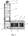
- Fig. 1 is a plan view of a hydraulic density separator 1 in accordance with a first example embodiment of the invention.
- the separator 1 comprises a first compartment 2, a second compartment 4 adjacent to a first side of the first compartment 2, and a third compartment 6 adjacent to a second side of the first compartment 2.
- the first and second sides of the first compartment 2 are at right angles to each other.
- a weir 18 divides the first compartment 2 from the second compartment 4.
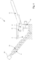
- a mesh screen 8 extends along the length of the second compartment 4 and has a first end 8a adjacent to the weir 18 and a second end 8b at the distal end of the second compartment. As is apparent from the isometric view of Fig. 2 , the mesh screen 8 is inclined such that the first end 8a is lower than the second end 8b.
- a screw auger 12 extends through the first compartment 2 (where it is located at the bottom of the first compartment) and into the third compartment 6. As is apparent from Fig. 2 , the auger 12 and the third compartment 6 are inclined such that the end of the auger 12 located in the first compartment 2 is lower than the end of the auger 12 located in the third compartment 6.
- a motor 14 is located at the distal end of the third compartment 6 and turns the auger 12.
- a slot 18 is located in the bottom of the third compartment 6 beneath the end of the auger 12.
- an axial pump 16 can be seen mounted on the separator 1 beneath the second compartment 4. It will be appreciated that other elements, for example the control system and electronics required to operate the separator 1 have not been included in Figs. 1 to 3 for the sake of clarity.
- the first compartment 2 Prior to operation, the first compartment 2 is filled with water.
- the material to be separated is introduced from above (for example, via an upwardly inclined conveyor - not shown) to the first compartment 2.
- the flow generator 16 generates an upflow of water in the first compartment 2.
- Lower density elements of the solids material to be separated will be entrained upwards by the flow of water, and carried over the weir 18 into the second compartment 4.
- the flow rate of the upflow may be increased or decreased by varying the power supplied to the pump 16 thereby enabling adjustment and/or alteration of the density threshold wherein elements of solids having a density greater than the threshold sink to the bottom of the compartment over time.
- separators in accordance with the present example embodiment may be more versatile than those of the prior art and may be able to separate a wider range of mixtures of materials, including mixtures where the difference in density between the higher and lower density elements in different mixture varies over a wide range.
- Separators in accordance with the present example embodiment may also offer improved separation of higher and lower density elements as the flow rate can be adjusted during the sorting process.
- separators in accordance with the present invention may reduce the volume of water required for the separation operation (because the water is recirculated) thereby avoiding the amount of contaminated water that must be safely disposed of after completion of the separation process.
- the mesh panel 8 has a grid-like structure defining a plurality of apertures 24.
- the apertures are elongate and have a width of about 2 mm and a length of about 20mm.
- water carrying lower density elements passes over the screen, and the elements on top of the screen while the water passes through the apertures 24.
- Separators in accordance with the present embodiment may offer an improved separation rate.
- Fig. 4 shows a schematic view of the hydraulic density separator.
- the arrow in the first compartment 2 indicate the upward flow of the water provided by the flow generator 16.
- the flow generator 16 creates an upward flow of water which is configured in such away that elements being slightly denser than water are carried to the second compartment 4.
- the elements being slightly denser than water may have a density between 1020 to 1300 kg/m 3 and/or have a density that is up to 25 % higher than the density of water, preferably between 2 % to 17 % higher than the density of water.
- the arrow in the second compartment 4 is directed to the ground which indicates that the lower density elements and the elements being slightly denser than water are transferred to the mesh panel 8.
- the mesh panel 8 can be a conveyer and/or can comprise one or more vibrators for vibrating the mesh screen.
- the height of the weir 18 can be adjusted according to the separation process.
- Fig. 4 shows that the weir 18 has a border which separates the first compartment 2 from the second compartment 4.
- the border of the weir 18 is rounded so that the grade of turbulence of the upward flow of water can be decreased, in particular between 10 % to 70 %.
- the pump 16 shown in Fig. 4 can be an axial water pump, in particular a dirt water pump.
- the hydraulic density separator 1 in the embodiment of Fig. 4 does not have throttles and/or valves.
- the pump 16 can be driven via a motor.
- the higher density elements can be lift up in the embodiment of Fig. 4 via an auger 12 which moves the higher density elements from the bottom of the first compartment 2 to third compartment 6.
- the motor of the pump 16 can be controlled, in particular to create the uplift and/or buoyancy for the upward flow of water in the first compartment 2.
- the higher density elements can be non-floatable elements, wherein the lower density elements are floatable elements and/or the elements being slightly denser than water are almost floatable elements which can be transported by the upward flow of water.
- the elements being slightly denser than water can be later used as RDF waste and/or burning material.
Landscapes
- Separation Of Solids By Using Liquids Or Pneumatic Power (AREA)
Claims (15)
- Hydraulischer Dichteabscheider zum Trennen von Elementen höherer Dichte und Elementen niedrigerer Dichte aus Feststoffmaterial, wobei die Vorrichtung umfasst:- eine erste Kammer (2) zur Aufnahme eines Gemisches, das Elemente höherer Dichte und Elemente niedrigerer Dichte sowie Wasser enthält;- einen Strömungsgenerator (16), der so konfiguriert ist, dass er eine aufwärts gerichtete Wasserströmung innerhalb der ersten Kammer (2) bereitstellt, wobei die Vorrichtung so konfiguriert ist, dass die Rate der Strömung eingestellt werden kann, um zu ermöglichen, dass die maximale Dichte von Elementen, die von der Strömung mitgerissen werden und aufwärts steigen, variiert werden kann;- Mittel in der ersten Kammer (2) zum Entfernen von Elementen höherer Dichte, die sich aus einem unteren Bereich der ersten Kammer (2) abgesetzt haben,- eine zweite Kammer (4) zum Aufnehmen einer Mischung, die Wasser und Elemente mit geringerer Dichte umfasst, aus der ersten Kammer (2), wobei die zweite Kammer (4) ein Maschensieb (8) umfasst, das so konfiguriert ist, dass es Elemente mit geringerer Dichte von einer ersten Position (8a) zu einer zweiten Position (8b) bewegt, die von der ersten Position (8a) beabstandet ist;- wobei ein Wasserströmungsweg von einem oberen Bereich der ersten Kammer in die zweite Kammer (4) und über einen Teil des Maschensiebs (8) vorgesehen ist, so dass Elemente mit geringerer Dichte, die von der Wasserströmung mitgerissen werden, auf dem Maschensieb abgelagert werden; und- wobei die Aufwärtsströmung des Wassers innerhalb der ersten Kammer (2), die durch den Strömungsgenerator bereitgestellt wird, so gestaltet ist, dass Elemente, die etwas dichter als Wasser sind, zur zweiten Kammer (4) getragen werden.
- Abscheider nach Anspruch 1, wobei sich der Strömungsweg nach dem Passieren eines Teils des Maschensiebs (8) von einem unteren Bereich der zweiten Kammer (4) zur ersten Kammer (2) fortsetzt.
- Abscheider nach einem der vorhergehenden Ansprüche, der außerdem einen oder mehrere Rüttler (10) zum Rütteln des Maschensiebs (8) umfasst.
- Abscheider nach einem der vorhergehenden Ansprüche, wobei das Maschensieb (8) als Förderer wirkt.
- Abscheider nach einem der vorhergehenden Ansprüche, ferner mit einer Schnecke (12), die teilweise innerhalb der ersten Kammer (2) angeordnet ist, um Elemente mit höherer Dichte zu entfernen, die sich aus einem unteren Bereich der ersten Kammer (2) abgesetzt haben.
- Abscheider nach einem der vorhergehenden Ansprüche, umfassend ein Wehr (18), das zwischen der ersten Kammer (2) und der zweiten Kammer (4) angeordnet ist, wobei der Strömungsweg vom oberen Bereich der ersten Kammer (2) zur zweiten Kammer (4) über das Wehr (18) verläuft.
- Abscheider nach einem der vorhergehenden Ansprüche, wobei die Öffnungen (24) im Sieb (8) länglich sind.
- Abscheider nach einem der vorhergehenden Ansprüche, wobei die Öffnungen (24) im Sieb (8) eine Breite im Bereich von 1 bis 5 mm aufweisen.
- Abscheider nach einem der vorhergehenden Ansprüche, wobei der Strömungsgenerator (16) eine Axialströmungspumpe umfasst.
- Verfahren zum Trennen von Elementen höherer Dichte und Elementen niedrigerer Dichte, wobei das Verfahren die folgenden Schritte umfasst:- Bereitstellung eines Separators (1) nach einem der vorhergehenden Ansprüche,- Einleiten von Wasser in die erste Kammer (2);- Einbringen einer Mischung aus Elementen unterschiedlicher Dichte in die erste Kammer (2);- Wasser von einem unteren Bereich der ersten Kammer (2) zu einem oberen Bereich der ersten Kammer (2) und von dem oberen Bereich der ersten Kammer (2) in eine zweite Kammer (4) und über das Maschensieb (8), das sich in der zweiten Kammer (4) befindet, zum Fließen bringen, wodurch Elemente mit einer Dichte, die kleiner als ein Schwellenwert ist, von der ersten Kammer (4) zu der zweiten Kammer (4) transportiert werden und die Elemente auf dem Sieb (8) abgelagert werden;- Transportieren der Elemente unter Verwendung des Siebes (8);- Entfernen von Elementen höherer Dichte aus einem unteren Bereich der ersten Kammer (2); und- Transportieren von Elementen, die geringfügig dichter als Wasser sind, insbesondere eine Dichte von 1020 bis 1300 kg/m3, vorzugsweise von 1100 bis 1250 kg/m3, aufweisen, innerhalb eines aufwärts gerichteten Wasserstroms, der durch einen Strömungsgenerator (16) des Abscheiders (1) von der ersten Kammer (2) zu der zweiten Kammer (4) bereitgestellt wird.
- Verfahren nach Anspruch 10, wobei das Gemisch Abfall umfasst, der einen oder mehrere der folgenden Bestandteile enthält: Steine, Erde, Zweige, Kunststoffgegenstände und/oder Blätter.
- Verfahren nach Anspruch 11, wobei die Elemente mit höherer Dichte Steine enthalten.
- Verfahren nach Anspruch 11 oder 12, wobei die Elemente mit geringerer Dichte Zweige umfassen.
- Verfahren nach einem der Ansprüche 10 bis 13, wobei das Verfahren den folgenden weiteren Schritt umfasst:- Wasser mit einer zweiten, unterschiedlichen Rate von einem unteren Bereich der ersten Kammer (2) zu einem oberen Bereich der ersten Kammer (2) und in eine zweite Kammer (4) zum Fließen bringen, wodurch Elemente mit einer Dichte, die geringer als ein zweiter, unterschiedlicher Schwellenwert ist, von der ersten Kammer (2) zu der zweiten Kammer (4) transportiert werden.
- Verwendung des Abscheiders (1) nach einem der Ansprüche 1 bis 9, dadurch gekennzeichnet, dass der Abscheider (1) zur Abtrennung von RDF-Abfallmaterial, Brennmaterial und nassem, gesättigtem Holz verwendet wird, das von Mischabfall und Bauschutt und/oder Bauabfall abgetrennt werden kann, die Teil der Gruppe "Elemente mit höherer Dichte" sind, wobei Elemente, die etwas dichter als Wasser sind, später als RDF-Abfall und/oder Brennmaterial verwendet werden können.
Priority Applications (1)
| Application Number | Priority Date | Filing Date | Title |
|---|---|---|---|
| PL19179588T PL3581276T3 (pl) | 2018-06-14 | 2019-06-12 | Hydrauliczny rozdzielacz gęstości |
Applications Claiming Priority (1)
| Application Number | Priority Date | Filing Date | Title |
|---|---|---|---|
| GB1809739.4A GB2574646A (en) | 2018-06-14 | 2018-06-14 | Hydraulic density separator |
Publications (2)
| Publication Number | Publication Date |
|---|---|
| EP3581276A1 EP3581276A1 (de) | 2019-12-18 |
| EP3581276B1 true EP3581276B1 (de) | 2021-05-05 |
Family
ID=63042428
Family Applications (1)
| Application Number | Title | Priority Date | Filing Date |
|---|---|---|---|
| EP19179588.9A Active EP3581276B1 (de) | 2018-06-14 | 2019-06-12 | Hydraulischer dichteabscheider |
Country Status (4)
| Country | Link |
|---|---|
| EP (1) | EP3581276B1 (de) |
| ES (1) | ES2874998T3 (de) |
| GB (1) | GB2574646A (de) |
| PL (1) | PL3581276T3 (de) |
Family Cites Families (9)
| Publication number | Priority date | Publication date | Assignee | Title |
|---|---|---|---|---|
| US2698087A (en) * | 1953-12-08 | 1954-12-28 | David L Call | Flotation separation tank |
| US3822015A (en) * | 1970-02-04 | 1974-07-02 | Battelle Development Corp | Separation of solids by varying the bulk density of a fluid separating medium |
| US3682299A (en) * | 1970-03-30 | 1972-08-08 | Vrain C Conley | Gravel washer and trash separator, process and apparatus |
| DD108906A1 (de) * | 1973-12-05 | 1974-10-12 | ||
| US4397424A (en) * | 1980-08-25 | 1983-08-09 | M.A. Industries, Inc. | Battery reclaiming method and apparatus |
| GB2407051A (en) * | 2003-09-19 | 2005-04-20 | Graham Andrew Sait | Object sorting apparatus by sink-float method |
| TWI404579B (zh) * | 2007-04-12 | 2013-08-11 | Small material waste disposal sorting device | |
| KR100804140B1 (ko) * | 2007-11-13 | 2008-02-19 | 주식회사 세창환경산업 | 순환골재의 이물질 선별장치 |
| ES2721783T3 (es) * | 2014-11-21 | 2019-08-05 | Wamgroup Spa | Un dispositivo de alimentación y una planta para la recuperación de residuos de hormigón |
-
2018
- 2018-06-14 GB GB1809739.4A patent/GB2574646A/en not_active Withdrawn
-
2019
- 2019-06-12 PL PL19179588T patent/PL3581276T3/pl unknown
- 2019-06-12 ES ES19179588T patent/ES2874998T3/es active Active
- 2019-06-12 EP EP19179588.9A patent/EP3581276B1/de active Active
Also Published As
| Publication number | Publication date |
|---|---|
| GB2574646A (en) | 2019-12-18 |
| ES2874998T3 (es) | 2021-11-08 |
| EP3581276A1 (de) | 2019-12-18 |
| PL3581276T3 (pl) | 2021-11-15 |
| GB201809739D0 (en) | 2018-08-01 |
Similar Documents
| Publication | Publication Date | Title |
|---|---|---|
| JP4829744B2 (ja) | 選別装置 | |
| AU2010214045B2 (en) | Hindered-settling fluid classifier | |
| US5110454A (en) | Apparatus for reclaiming gravel, soil particles and wood pieces from a mixture of the same | |
| CA2608239A1 (en) | Process and device for separating plastics of different chemical composition by flotation | |
| JP5292483B2 (ja) | 湿式選別装置 | |
| JP4678627B2 (ja) | 洗浄処理方法ならびに洗浄処理装置 | |
| KR100534680B1 (ko) | 건설폐기물의 이물질 선별 제거장치 및 이에 사용되는보충수의 재사용 방법 | |
| US20080135461A1 (en) | Dense medium separator | |
| US20080121574A1 (en) | Device for the separation of waste materials in accordance with their densities | |
| US5240114A (en) | Process for reclaiming gravel, soil particles, and wood pieces from a mixture of the same | |
| US20200147651A1 (en) | Density separator for waste material | |
| EP3581276B1 (de) | Hydraulischer dichteabscheider | |
| NL1022854C2 (nl) | Werkwijze en inrichting voor het reinigen van stranden. | |
| KR101632166B1 (ko) | 건설폐기물 습식 분류장치의 저류-정수조 | |
| KR102395318B1 (ko) | 회수된 폐어망의 세척분리장치 | |
| JP3973716B2 (ja) | 骨材に混入した軽質物質を除去する方法及び装置 | |
| JP2016125277A (ja) | 浚渫システム | |
| JP4931841B2 (ja) | 湿式選別装置 | |
| KR101531236B1 (ko) | 협잡물 종합처리장치 | |
| KR20020023875A (ko) | 건축폐기물 습식 분류장치 | |
| EP0469360B1 (de) | Verfahren und Vorrichtung zum nassen Trennen von heterogenen Mischungen aus Feststoffen unterschiedlicher Dichte | |
| JP2001129426A (ja) | 洗浄処理装置 | |
| EP0647483A1 (de) | Verfahren und Anlage zur Reinigung von verunreinigtem Sedimentmaterial | |
| US3420371A (en) | Heavy medium separator | |
| JPH09299825A (ja) | 骨材に混入した軽質物質の除去方法及び装置 |
Legal Events
| Date | Code | Title | Description |
|---|---|---|---|
| PUAI | Public reference made under article 153(3) epc to a published international application that has entered the european phase |
Free format text: ORIGINAL CODE: 0009012 |
|
| STAA | Information on the status of an ep patent application or granted ep patent |
Free format text: STATUS: THE APPLICATION HAS BEEN PUBLISHED |
|
| AK | Designated contracting states |
Kind code of ref document: A1 Designated state(s): AL AT BE BG CH CY CZ DE DK EE ES FI FR GB GR HR HU IE IS IT LI LT LU LV MC MK MT NL NO PL PT RO RS SE SI SK SM TR |
|
| AX | Request for extension of the european patent |
Extension state: BA ME |
|
| STAA | Information on the status of an ep patent application or granted ep patent |
Free format text: STATUS: REQUEST FOR EXAMINATION WAS MADE |
|
| 17P | Request for examination filed |
Effective date: 20200109 |
|
| RBV | Designated contracting states (corrected) |
Designated state(s): AL AT BE BG CH CY CZ DE DK EE ES FI FR GB GR HR HU IE IS IT LI LT LU LV MC MK MT NL NO PL PT RO RS SE SI SK SM TR |
|
| RAP1 | Party data changed (applicant data changed or rights of an application transferred) |
Owner name: LIG GMBH |
|
| GRAP | Despatch of communication of intention to grant a patent |
Free format text: ORIGINAL CODE: EPIDOSNIGR1 |
|
| STAA | Information on the status of an ep patent application or granted ep patent |
Free format text: STATUS: GRANT OF PATENT IS INTENDED |
|
| INTG | Intention to grant announced |
Effective date: 20201217 |
|
| GRAS | Grant fee paid |
Free format text: ORIGINAL CODE: EPIDOSNIGR3 |
|
| GRAA | (expected) grant |
Free format text: ORIGINAL CODE: 0009210 |
|
| STAA | Information on the status of an ep patent application or granted ep patent |
Free format text: STATUS: THE PATENT HAS BEEN GRANTED |
|
| AK | Designated contracting states |
Kind code of ref document: B1 Designated state(s): AL AT BE BG CH CY CZ DE DK EE ES FI FR GB GR HR HU IE IS IT LI LT LU LV MC MK MT NL NO PL PT RO RS SE SI SK SM TR |
|
| REG | Reference to a national code |
Ref country code: GB Ref legal event code: FG4D |
|
| REG | Reference to a national code |
Ref country code: CH Ref legal event code: EP |
|
| REG | Reference to a national code |
Ref country code: AT Ref legal event code: REF Ref document number: 1389129 Country of ref document: AT Kind code of ref document: T Effective date: 20210515 |
|
| REG | Reference to a national code |
Ref country code: IE Ref legal event code: FG4D |
|
| REG | Reference to a national code |
Ref country code: DE Ref legal event code: R096 Ref document number: 602019004396 Country of ref document: DE |
|
| REG | Reference to a national code |
Ref country code: NL Ref legal event code: FP |
|
| REG | Reference to a national code |
Ref country code: DE Ref legal event code: R081 Ref document number: 602019004396 Country of ref document: DE Owner name: LIG GMBH, DE Free format text: FORMER OWNER: LIG GMBH, 42555 VELBERT, DE |
|
| RAP4 | Party data changed (patent owner data changed or rights of a patent transferred) |
Owner name: LIG GMBH |
|
| REG | Reference to a national code |
Ref country code: LT Ref legal event code: MG9D |
|
| PG25 | Lapsed in a contracting state [announced via postgrant information from national office to epo] |
Ref country code: HR Free format text: LAPSE BECAUSE OF FAILURE TO SUBMIT A TRANSLATION OF THE DESCRIPTION OR TO PAY THE FEE WITHIN THE PRESCRIBED TIME-LIMIT Effective date: 20210505 Ref country code: LT Free format text: LAPSE BECAUSE OF FAILURE TO SUBMIT A TRANSLATION OF THE DESCRIPTION OR TO PAY THE FEE WITHIN THE PRESCRIBED TIME-LIMIT Effective date: 20210505 Ref country code: FI Free format text: LAPSE BECAUSE OF FAILURE TO SUBMIT A TRANSLATION OF THE DESCRIPTION OR TO PAY THE FEE WITHIN THE PRESCRIBED TIME-LIMIT Effective date: 20210505 Ref country code: BG Free format text: LAPSE BECAUSE OF FAILURE TO SUBMIT A TRANSLATION OF THE DESCRIPTION OR TO PAY THE FEE WITHIN THE PRESCRIBED TIME-LIMIT Effective date: 20210805 |
|
| REG | Reference to a national code |
Ref country code: ES Ref legal event code: FG2A Ref document number: 2874998 Country of ref document: ES Kind code of ref document: T3 Effective date: 20211108 |
|
| PG25 | Lapsed in a contracting state [announced via postgrant information from national office to epo] |
Ref country code: NO Free format text: LAPSE BECAUSE OF FAILURE TO SUBMIT A TRANSLATION OF THE DESCRIPTION OR TO PAY THE FEE WITHIN THE PRESCRIBED TIME-LIMIT Effective date: 20210805 Ref country code: LV Free format text: LAPSE BECAUSE OF FAILURE TO SUBMIT A TRANSLATION OF THE DESCRIPTION OR TO PAY THE FEE WITHIN THE PRESCRIBED TIME-LIMIT Effective date: 20210505 Ref country code: RS Free format text: LAPSE BECAUSE OF FAILURE TO SUBMIT A TRANSLATION OF THE DESCRIPTION OR TO PAY THE FEE WITHIN THE PRESCRIBED TIME-LIMIT Effective date: 20210505 Ref country code: SE Free format text: LAPSE BECAUSE OF FAILURE TO SUBMIT A TRANSLATION OF THE DESCRIPTION OR TO PAY THE FEE WITHIN THE PRESCRIBED TIME-LIMIT Effective date: 20210505 Ref country code: PT Free format text: LAPSE BECAUSE OF FAILURE TO SUBMIT A TRANSLATION OF THE DESCRIPTION OR TO PAY THE FEE WITHIN THE PRESCRIBED TIME-LIMIT Effective date: 20210906 Ref country code: GR Free format text: LAPSE BECAUSE OF FAILURE TO SUBMIT A TRANSLATION OF THE DESCRIPTION OR TO PAY THE FEE WITHIN THE PRESCRIBED TIME-LIMIT Effective date: 20210806 Ref country code: IS Free format text: LAPSE BECAUSE OF FAILURE TO SUBMIT A TRANSLATION OF THE DESCRIPTION OR TO PAY THE FEE WITHIN THE PRESCRIBED TIME-LIMIT Effective date: 20210905 |
|
| PG25 | Lapsed in a contracting state [announced via postgrant information from national office to epo] |
Ref country code: SM Free format text: LAPSE BECAUSE OF FAILURE TO SUBMIT A TRANSLATION OF THE DESCRIPTION OR TO PAY THE FEE WITHIN THE PRESCRIBED TIME-LIMIT Effective date: 20210505 Ref country code: RO Free format text: LAPSE BECAUSE OF FAILURE TO SUBMIT A TRANSLATION OF THE DESCRIPTION OR TO PAY THE FEE WITHIN THE PRESCRIBED TIME-LIMIT Effective date: 20210505 Ref country code: DK Free format text: LAPSE BECAUSE OF FAILURE TO SUBMIT A TRANSLATION OF THE DESCRIPTION OR TO PAY THE FEE WITHIN THE PRESCRIBED TIME-LIMIT Effective date: 20210505 Ref country code: CZ Free format text: LAPSE BECAUSE OF FAILURE TO SUBMIT A TRANSLATION OF THE DESCRIPTION OR TO PAY THE FEE WITHIN THE PRESCRIBED TIME-LIMIT Effective date: 20210505 Ref country code: SK Free format text: LAPSE BECAUSE OF FAILURE TO SUBMIT A TRANSLATION OF THE DESCRIPTION OR TO PAY THE FEE WITHIN THE PRESCRIBED TIME-LIMIT Effective date: 20210505 Ref country code: EE Free format text: LAPSE BECAUSE OF FAILURE TO SUBMIT A TRANSLATION OF THE DESCRIPTION OR TO PAY THE FEE WITHIN THE PRESCRIBED TIME-LIMIT Effective date: 20210505 |
|
| REG | Reference to a national code |
Ref country code: DE Ref legal event code: R097 Ref document number: 602019004396 Country of ref document: DE |
|
| PLBE | No opposition filed within time limit |
Free format text: ORIGINAL CODE: 0009261 |
|
| STAA | Information on the status of an ep patent application or granted ep patent |
Free format text: STATUS: NO OPPOSITION FILED WITHIN TIME LIMIT |
|
| PG25 | Lapsed in a contracting state [announced via postgrant information from national office to epo] |
Ref country code: MC Free format text: LAPSE BECAUSE OF FAILURE TO SUBMIT A TRANSLATION OF THE DESCRIPTION OR TO PAY THE FEE WITHIN THE PRESCRIBED TIME-LIMIT Effective date: 20210505 Ref country code: LU Free format text: LAPSE BECAUSE OF NON-PAYMENT OF DUE FEES Effective date: 20210612 |
|
| 26N | No opposition filed |
Effective date: 20220208 |
|
| PG25 | Lapsed in a contracting state [announced via postgrant information from national office to epo] |
Ref country code: IE Free format text: LAPSE BECAUSE OF NON-PAYMENT OF DUE FEES Effective date: 20210612 |
|
| PG25 | Lapsed in a contracting state [announced via postgrant information from national office to epo] |
Ref country code: IS Free format text: LAPSE BECAUSE OF FAILURE TO SUBMIT A TRANSLATION OF THE DESCRIPTION OR TO PAY THE FEE WITHIN THE PRESCRIBED TIME-LIMIT Effective date: 20210905 Ref country code: AL Free format text: LAPSE BECAUSE OF FAILURE TO SUBMIT A TRANSLATION OF THE DESCRIPTION OR TO PAY THE FEE WITHIN THE PRESCRIBED TIME-LIMIT Effective date: 20210505 |
|
| REG | Reference to a national code |
Ref country code: AT Ref legal event code: UEP Ref document number: 1389129 Country of ref document: AT Kind code of ref document: T Effective date: 20210505 |
|
| REG | Reference to a national code |
Ref country code: CH Ref legal event code: PL |
|
| PG25 | Lapsed in a contracting state [announced via postgrant information from national office to epo] |
Ref country code: LI Free format text: LAPSE BECAUSE OF NON-PAYMENT OF DUE FEES Effective date: 20220630 Ref country code: CH Free format text: LAPSE BECAUSE OF NON-PAYMENT OF DUE FEES Effective date: 20220630 |
|
| PG25 | Lapsed in a contracting state [announced via postgrant information from national office to epo] |
Ref country code: CY Free format text: LAPSE BECAUSE OF FAILURE TO SUBMIT A TRANSLATION OF THE DESCRIPTION OR TO PAY THE FEE WITHIN THE PRESCRIBED TIME-LIMIT Effective date: 20210505 |
|
| P01 | Opt-out of the competence of the unified patent court (upc) registered |
Effective date: 20230613 |
|
| PG25 | Lapsed in a contracting state [announced via postgrant information from national office to epo] |
Ref country code: HU Free format text: LAPSE BECAUSE OF FAILURE TO SUBMIT A TRANSLATION OF THE DESCRIPTION OR TO PAY THE FEE WITHIN THE PRESCRIBED TIME-LIMIT; INVALID AB INITIO Effective date: 20190612 |
|
| PGFP | Annual fee paid to national office [announced via postgrant information from national office to epo] |
Ref country code: NL Payment date: 20230620 Year of fee payment: 5 Ref country code: FR Payment date: 20230628 Year of fee payment: 5 Ref country code: DE Payment date: 20230615 Year of fee payment: 5 |
|
| PGFP | Annual fee paid to national office [announced via postgrant information from national office to epo] |
Ref country code: TR Payment date: 20230609 Year of fee payment: 5 Ref country code: PL Payment date: 20230602 Year of fee payment: 5 |
|
| PGFP | Annual fee paid to national office [announced via postgrant information from national office to epo] |
Ref country code: BE Payment date: 20230620 Year of fee payment: 5 |
|
| PGFP | Annual fee paid to national office [announced via postgrant information from national office to epo] |
Ref country code: IT Payment date: 20230623 Year of fee payment: 5 Ref country code: GB Payment date: 20230622 Year of fee payment: 5 Ref country code: ES Payment date: 20230830 Year of fee payment: 5 |
|
| PG25 | Lapsed in a contracting state [announced via postgrant information from national office to epo] |
Ref country code: MK Free format text: LAPSE BECAUSE OF FAILURE TO SUBMIT A TRANSLATION OF THE DESCRIPTION OR TO PAY THE FEE WITHIN THE PRESCRIBED TIME-LIMIT Effective date: 20210505 |