EP3580040B1 - Industrielle maschine zur senkrechten auftragung von vorübergehenden oder permanenten schutzfilmen auf ebene oberflächen - Google Patents
Industrielle maschine zur senkrechten auftragung von vorübergehenden oder permanenten schutzfilmen auf ebene oberflächen Download PDFInfo
- Publication number
- EP3580040B1 EP3580040B1 EP17729004.6A EP17729004A EP3580040B1 EP 3580040 B1 EP3580040 B1 EP 3580040B1 EP 17729004 A EP17729004 A EP 17729004A EP 3580040 B1 EP3580040 B1 EP 3580040B1
- Authority
- EP
- European Patent Office
- Prior art keywords
- film
- roller
- product
- protected
- coating
- Prior art date
- Legal status (The legal status is an assumption and is not a legal conclusion. Google has not performed a legal analysis and makes no representation as to the accuracy of the status listed.)
- Active
Links
- 230000004224 protection Effects 0.000 title claims description 13
- 239000011521 glass Substances 0.000 claims description 39
- 238000005520 cutting process Methods 0.000 claims description 22
- 238000000034 method Methods 0.000 claims description 11
- 230000001681 protective effect Effects 0.000 claims description 11
- 239000011248 coating agent Substances 0.000 claims description 5
- 238000000576 coating method Methods 0.000 claims description 5
- 229920001296 polysiloxane Polymers 0.000 claims description 4
- 239000007888 film coating Substances 0.000 claims 19
- 238000009501 film coating Methods 0.000 claims 19
- 230000000712 assembly Effects 0.000 claims 1
- 238000000429 assembly Methods 0.000 claims 1
- 238000005516 engineering process Methods 0.000 description 33
- 238000003475 lamination Methods 0.000 description 28
- 241001639412 Verres Species 0.000 description 13
- 239000000758 substrate Substances 0.000 description 10
- 230000000873 masking effect Effects 0.000 description 9
- 238000004519 manufacturing process Methods 0.000 description 8
- 239000000463 material Substances 0.000 description 7
- 238000000151 deposition Methods 0.000 description 4
- 238000001514 detection method Methods 0.000 description 3
- 238000010030 laminating Methods 0.000 description 3
- 230000004075 alteration Effects 0.000 description 2
- 238000010276 construction Methods 0.000 description 2
- 238000006073 displacement reaction Methods 0.000 description 2
- 230000000694 effects Effects 0.000 description 2
- KWGRBVOPPLSCSI-WPRPVWTQSA-N (-)-ephedrine Chemical compound CN[C@@H](C)[C@H](O)C1=CC=CC=C1 KWGRBVOPPLSCSI-WPRPVWTQSA-N 0.000 description 1
- RJFAYQIBOAGBLC-UHFFFAOYSA-N Selenomethionine Natural products C[Se]CCC(N)C(O)=O RJFAYQIBOAGBLC-UHFFFAOYSA-N 0.000 description 1
- 230000001609 comparable effect Effects 0.000 description 1
- 238000007786 electrostatic charging Methods 0.000 description 1
- 235000021183 entrée Nutrition 0.000 description 1
- 239000005357 flat glass Substances 0.000 description 1
- 238000010438 heat treatment Methods 0.000 description 1
- 238000009434 installation Methods 0.000 description 1
- 238000005259 measurement Methods 0.000 description 1
- 230000002093 peripheral effect Effects 0.000 description 1
- 238000007747 plating Methods 0.000 description 1
- 230000001869 rapid Effects 0.000 description 1
- 238000005096 rolling process Methods 0.000 description 1
- 238000006748 scratching Methods 0.000 description 1
- 230000002393 scratching effect Effects 0.000 description 1
- 239000002699 waste material Substances 0.000 description 1
Images

Classifications
-
- B—PERFORMING OPERATIONS; TRANSPORTING
- B29—WORKING OF PLASTICS; WORKING OF SUBSTANCES IN A PLASTIC STATE IN GENERAL
- B29C—SHAPING OR JOINING OF PLASTICS; SHAPING OF MATERIAL IN A PLASTIC STATE, NOT OTHERWISE PROVIDED FOR; AFTER-TREATMENT OF THE SHAPED PRODUCTS, e.g. REPAIRING
- B29C63/00—Lining or sheathing, i.e. applying preformed layers or sheathings of plastics; Apparatus therefor
- B29C63/02—Lining or sheathing, i.e. applying preformed layers or sheathings of plastics; Apparatus therefor using sheet or web-like material
- B29C63/024—Lining or sheathing, i.e. applying preformed layers or sheathings of plastics; Apparatus therefor using sheet or web-like material the sheet or web-like material being supported by a moving carriage
-
- B—PERFORMING OPERATIONS; TRANSPORTING
- B29—WORKING OF PLASTICS; WORKING OF SUBSTANCES IN A PLASTIC STATE IN GENERAL
- B29C—SHAPING OR JOINING OF PLASTICS; SHAPING OF MATERIAL IN A PLASTIC STATE, NOT OTHERWISE PROVIDED FOR; AFTER-TREATMENT OF THE SHAPED PRODUCTS, e.g. REPAIRING
- B29C63/00—Lining or sheathing, i.e. applying preformed layers or sheathings of plastics; Apparatus therefor
- B29C63/0043—Fixing the layers by electrostatic charges, by the use of structured surfaces or by mechanical means
-
- B—PERFORMING OPERATIONS; TRANSPORTING
- B29—WORKING OF PLASTICS; WORKING OF SUBSTANCES IN A PLASTIC STATE IN GENERAL
- B29C—SHAPING OR JOINING OF PLASTICS; SHAPING OF MATERIAL IN A PLASTIC STATE, NOT OTHERWISE PROVIDED FOR; AFTER-TREATMENT OF THE SHAPED PRODUCTS, e.g. REPAIRING
- B29C63/00—Lining or sheathing, i.e. applying preformed layers or sheathings of plastics; Apparatus therefor
- B29C63/0056—Provisional sheathings
-
- B—PERFORMING OPERATIONS; TRANSPORTING
- B32—LAYERED PRODUCTS
- B32B—LAYERED PRODUCTS, i.e. PRODUCTS BUILT-UP OF STRATA OF FLAT OR NON-FLAT, e.g. CELLULAR OR HONEYCOMB, FORM
- B32B17/00—Layered products essentially comprising sheet glass, or glass, slag, or like fibres
- B32B17/06—Layered products essentially comprising sheet glass, or glass, slag, or like fibres comprising glass as the main or only constituent of a layer, next to another layer of a specific material
- B32B17/10—Layered products essentially comprising sheet glass, or glass, slag, or like fibres comprising glass as the main or only constituent of a layer, next to another layer of a specific material of synthetic resin
-
- B—PERFORMING OPERATIONS; TRANSPORTING
- B32—LAYERED PRODUCTS
- B32B—LAYERED PRODUCTS, i.e. PRODUCTS BUILT-UP OF STRATA OF FLAT OR NON-FLAT, e.g. CELLULAR OR HONEYCOMB, FORM
- B32B37/00—Methods or apparatus for laminating, e.g. by curing or by ultrasonic bonding
- B32B37/02—Methods or apparatus for laminating, e.g. by curing or by ultrasonic bonding characterised by a sequence of laminating steps, e.g. by adding new layers at consecutive laminating stations
-
- B—PERFORMING OPERATIONS; TRANSPORTING
- B32—LAYERED PRODUCTS
- B32B—LAYERED PRODUCTS, i.e. PRODUCTS BUILT-UP OF STRATA OF FLAT OR NON-FLAT, e.g. CELLULAR OR HONEYCOMB, FORM
- B32B37/00—Methods or apparatus for laminating, e.g. by curing or by ultrasonic bonding
- B32B37/10—Methods or apparatus for laminating, e.g. by curing or by ultrasonic bonding characterised by the pressing technique, e.g. using action of vacuum or fluid pressure
-
- B—PERFORMING OPERATIONS; TRANSPORTING
- B32—LAYERED PRODUCTS
- B32B—LAYERED PRODUCTS, i.e. PRODUCTS BUILT-UP OF STRATA OF FLAT OR NON-FLAT, e.g. CELLULAR OR HONEYCOMB, FORM
- B32B37/00—Methods or apparatus for laminating, e.g. by curing or by ultrasonic bonding
- B32B37/14—Methods or apparatus for laminating, e.g. by curing or by ultrasonic bonding characterised by the properties of the layers
- B32B37/16—Methods or apparatus for laminating, e.g. by curing or by ultrasonic bonding characterised by the properties of the layers with all layers existing as coherent layers before laminating
- B32B37/22—Methods or apparatus for laminating, e.g. by curing or by ultrasonic bonding characterised by the properties of the layers with all layers existing as coherent layers before laminating involving the assembly of both discrete and continuous layers
- B32B37/223—One or more of the layers being plastic
-
- B—PERFORMING OPERATIONS; TRANSPORTING
- B32—LAYERED PRODUCTS
- B32B—LAYERED PRODUCTS, i.e. PRODUCTS BUILT-UP OF STRATA OF FLAT OR NON-FLAT, e.g. CELLULAR OR HONEYCOMB, FORM
- B32B38/00—Ancillary operations in connection with laminating processes
- B32B38/0004—Cutting, tearing or severing, e.g. bursting; Cutter details
-
- B—PERFORMING OPERATIONS; TRANSPORTING
- B32—LAYERED PRODUCTS
- B32B—LAYERED PRODUCTS, i.e. PRODUCTS BUILT-UP OF STRATA OF FLAT OR NON-FLAT, e.g. CELLULAR OR HONEYCOMB, FORM
- B32B41/00—Arrangements for controlling or monitoring lamination processes; Safety arrangements
-
- B—PERFORMING OPERATIONS; TRANSPORTING
- B29—WORKING OF PLASTICS; WORKING OF SUBSTANCES IN A PLASTIC STATE IN GENERAL
- B29L—INDEXING SCHEME ASSOCIATED WITH SUBCLASS B29C, RELATING TO PARTICULAR ARTICLES
- B29L2031/00—Other particular articles
- B29L2031/778—Windows
- B29L2031/7782—Glazing
-
- B—PERFORMING OPERATIONS; TRANSPORTING
- B32—LAYERED PRODUCTS
- B32B—LAYERED PRODUCTS, i.e. PRODUCTS BUILT-UP OF STRATA OF FLAT OR NON-FLAT, e.g. CELLULAR OR HONEYCOMB, FORM
- B32B2250/00—Layers arrangement
- B32B2250/03—3 layers
-
- B—PERFORMING OPERATIONS; TRANSPORTING
- B32—LAYERED PRODUCTS
- B32B—LAYERED PRODUCTS, i.e. PRODUCTS BUILT-UP OF STRATA OF FLAT OR NON-FLAT, e.g. CELLULAR OR HONEYCOMB, FORM
- B32B2250/00—Layers arrangement
- B32B2250/40—Symmetrical or sandwich layers, e.g. ABA, ABCBA, ABCCBA
-
- B—PERFORMING OPERATIONS; TRANSPORTING
- B32—LAYERED PRODUCTS
- B32B—LAYERED PRODUCTS, i.e. PRODUCTS BUILT-UP OF STRATA OF FLAT OR NON-FLAT, e.g. CELLULAR OR HONEYCOMB, FORM
- B32B2307/00—Properties of the layers or laminate
- B32B2307/50—Properties of the layers or laminate having particular mechanical properties
- B32B2307/584—Scratch resistance
Definitions
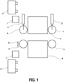
- the invention relates to an industrial machine for the vertical application of temporary or permanent protective films on flat surfaces having an automatic system for cutting the film, for positioning edge to edge or with a margin (in particular in the context of the lamination of panes, for the purpose of mounting the glazing on the frame of doors or windows without altering the temporary protection; the pane having received a reservation) acting simultaneously on both sides and automatically adapting to changes in the format of the parts to be treated, according to a electrostatic method of holding the film in position on the applicator roller.
- Glass manufacturers have another constraint in that the glass products manufactured are constantly of different sizes, and that manufacturing takes place continuously regardless of the dimensions requested, so that the panes come out of production one after the other whatever the dimensions (the assembly lines of glazing are designed for the manufacture of large quantities of products with different dimensions, and not for large series glazing of the same size; while they generally produce a glazing in less than a minute). It is therefore important that during the manufacturing cycle, the automated filming technology automatically detects the size of the pane and that it places the protection on both sides without any human intervention.
- glazing manufacturers generally manufacture, store and handle their products vertically; which indicates that the lamination process must be carried out in such a way as to transport, film and release the substrates vertically, generally inclined at 6°.
- the patent application EP 1 884 346 describes a machine for continuously applying protective films to both sides of glass parts to be coated. This machine comprises two lamination modules arranged on either side of the parts to be laminated. The glass pieces are then cut to the desired measurements.
- the patent application US 2016/176171 discloses a method and system for applying masking material to a planar substrate comprising a masking material application station where masking material is applied to an applicator roller and a transfer station where at least a portion of the Masking is transferred from the roller to a flat workpiece surface.
- the applicator roller may use electrostatic force to keep the masking material in contact with the roller.
- the patent application EP 0 316 224 describes a device for assembling laminated glazing using in particular a sheet manipulated by a gripping system using, for example, suction or electrostatic plating.
- the patent application US 20003/087592 describes a method for coating a part with the aid of a masking material consisting in precutting a mask in the sheet of masking material before ensuring the application of the part on the mask in order to ensure the detachment of the mask relative to the sheet of masking material.
- the patent application EP 3 034 275 also describes a masking machine for depositing a protective mask on glazing panels.
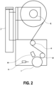
- the lamination module (r and s) differs in that it incorporates the detour roller (o) and the reel holder mandrel (q).
Landscapes
- Engineering & Computer Science (AREA)
- Manufacturing & Machinery (AREA)
- Physics & Mathematics (AREA)
- Fluid Mechanics (AREA)
- Application Of Or Painting With Fluid Materials (AREA)
- Lining Or Joining Of Plastics Or The Like (AREA)
- Laminated Bodies (AREA)
Claims (5)
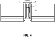
- Industrielle Maschine zur senkrechten Aufbringung von vorübergehenden oder permanenten Schutzfolien gleichzeitig auf die zwei ebenen Oberflächen der Vorder- und Rückseite zu schützender Produkte mit automatischem Zuschnitt der Folien und Kante-an-Kante-Positionierung oder mit Rand und automatischer Anpassung an Formatänderungen, wobei diese Maschine aufweist:▪ eine Gesamtstruktur, die mit einem Transport- und Positionierungssystem des zu schützenden Produkts versehen ist, aufweisend:· mindestens eine motorisierte Einführwalze (a) an fester Position und mindestens eine freie und horizontal bewegliche Einführwalze (b), die von Zylindern (c) betätigt wird, wobei die freie Einführwalze (b) im Verhältnis zur motorisierten Einführwalze (a) symmetrisch ist, um das zu schützende Produkte zu transportieren und am Eingang zu positionieren;· mindestens eine motorisierte Auswurfwalze an fester Position (e) und mindestens eine freie und bewegliche Auswurfwalze (f), die sich horizontal bewegt und von Zylindern (g) betätigt wird, wobei die freie und bewegliche Auswurfwalze (f) im Verhältnis zur motorisierten Auswurfwalze symmetrisch ist, um das zu schützende Produkt zu transportieren und am Ausgang zu positionieren,· eine Detektionszelle (d) nach der oder den Einführwalzen (a) und (b), um die Position des zu schützenden Produkts und der hinteren Kante des zu schützenden Produkts zu bestimmen;· zwei vertikale Balken mit linearen Führungen (h) und zwei Vertikalverlagerungseinheiten (i) für die Bewegung und die vertikale Positionierung von Laminiermodulen (r, s);▪ zwei Laminiermodule (r) und (s), die auf den vertikalen Balken mit linearen Führungen der Struktur platziert sind, um deren vertikale und horizontale Verlagerungen zu sichern, wobei ein Modul das Laminieren der Vorderseite des zu schützenden Produkts sichert, wohingegen das andere Modul das Laminieren der Rückseite desselben zu schützenden Produkts sichert, wobei jedes Laminiermodul aufweist:· eine Auftragswalze (I), die die Folie auf das zu schützende Produkt ab ihrer unteren Achse laminiert und die die Folie durch elektrostatische Ladung auf der Auftragswalze hält;· ein Schneidemodul (n) zum Zuschneiden der Folie im Kontakt mit der Auftragswalze (I) in einem Abstand von der unteren Achse der Auftragswalze, der äquivalent zum Abstand zwischen der unteren Achse der Auftragswalze und der hinteren Kante des zu schützenden Produkts plus Rand ist;▪ einen Automaten mit einem Programm zur Steuerung der verschiedenen Module der Maschine in Abhängigkeit von der Größe der zu schützenden Produkte, wobei für jedes zu schützende Produkt der Automat steuert:· die motorisierte Einführwalze (a) zur seitlichen Verlagerung des zu schützenden Produkts, um es zwischen den zwei Laminiermodulen (r) und (s) mit der Kante des zu schützenden Produkts in einem Abstand von der Achse der Auftragswalzen (I) zu positionieren, der äquivalent zu dem Rand ist, der frei bleiben muss, wobei die Kante der Folie in der Achse der Auftragswalzen (I) positioniert ist,· die zwei Laminiermodule (r) und (s), um das Laminieren der Vorder- und Rückseite des zu schützenden Produkts zu gestatten,· die motorisierte Einführwalze (a) zur seitlichen Verlagerung des zu schützenden Produkts, um das Laminieren seiner Vorder- und Rückseite zu sichern,· die Auswurfwalze (e), um die hintere Kante des zu schützenden Produkts in einem Abstand von der Achse der Auftragswalze (l) zu positionieren, der äquivalent zum Abstand zwischen der unteren Achse der Auftragswalze und der Trennstelle plus Rand ist,· das Schneidemodul zum Schneiden der Folie,· die Auswurfwalze (e) zum Positionieren der hinteren Kante in einem Abstand von der Achse der Auftragswalze (l), der äquivalent zum Rand ist,· und die zwei sich zur Freigabe des Produkts öffnenden Laminiermodule (r) und (s).
- Industrielle Maschine nach Anspruch 1, dadurch gekennzeichnet, dass jedes Laminiermodul (r) und (s) aufweist:▪ eine elektrostatische Ladungsstange (m), die mit einem Ladungsgenerator verbunden und in einem Abstand zwischen 5 und 25 mm von der Auftragswalze (I) positioniert ist, so dass die Folie an der Auftragswalze (I) bei genauer Beibehaltung ihrer Position anhaften kann;▪ eine Umleitungswalze (o), die erlaubt, einen genauen Winkel zwischen der Folienspule und der Auftragswalze (I) beizubehalten;▪ eine Gegenwalze aus Silikon (p), die die Kontaktfläche zwischen der Folie und der Auftragswalze (I) vergrößert, um die Folie unter der Ladungsstange zu positionieren und die Folie unter der Walze (I) zu halten;▪ einen Folienspulenträgerdorn (q), der mit einem Abrollbremssystem ausgestattet ist.
- Industrielle Maschine nach Anspruch 2, dadurch gekennzeichnet, dass das Vorderseiten-Laminiermodul (r) auf einem Zylinder mit einer linearen Führung (j) angebracht ist, um sich horizontal in dem Abstand zu positionieren, der in Abhängigkeit von der Dicke des zu schützenden Produkts notwendig ist und den adäquaten Laminierdruck auszuüben.
- Industrielle Maschine nach Anspruch 1, dadurch gekennzeichnet, dass das auf einem Schwingarmsystem (k) bewegliche Rückseiten-Laminiermodul (s) zwei Positionen aufweist: eingefahren, wenn das Modul mit dem zu laminierenden Produkt nicht im Kontakt ist, ausgefahren, wenn am Nullpunkt positioniert, wobei die Auftragswalze (I) parallel und in der Verlängerung der Einführ- (a) und Auswurfwalzen (e) zum Laminieren des zu schützenden Produkts ist.
- Verfahren zum Aufbringen von vorübergehenden oder permanenten Schutzfolien, das eine Maschine nach Anspruch 1 verwendet, dadurch gekennzeichnet, dass die automatisierte Steuerung der verschiedenen Module und Bauteile der Maschine in folgender Reihenfolge erfolgt:▪ der Bediener legt als zu schützendes Produkt eine Scheibe ab und startet den Zyklus;▪ das Glas verlagert sich zur Maschine, wobei diese von anderen Mitteln informiert wurde, die erlauben, die zur vollständigen Abdeckung der Scheibe notwendige Anzahl der Bahnen zu berechnen;▪ die zwei Laminiermodule (r) und (s) positionieren sich in einer bestimmten Höhe derart, dass sich der untere Teil der Folienspule in der Höhe der unteren Kante der Scheibe plus Höhe des Randes befindet;▪ das Glas verlagert sich seitlich, die Einführwalzen (a) und (b) schließen sich und positionieren die Scheibe zwischen den zwei Laminiermodulen (r) und (s) mit der Kante des Glases in einem Abstand von der Vertikalen der Achse der Auftragswalzen (I), der äquivalent zum Rand ist, der für die zukünftige Montage der Rahmen frei bleiben muss, wobei die Kante der Folie in der Achse der Auftragswalzen (I) positioniert ist;▪ das Rückseiten-Laminiermodul (s) bewegt sich vorwärts, um sich am Nullpunkt in der Flucht der Einführ-(a) und (b) und Auswurfwalzen (e) und (f) im Kontakt mit dem Glas zu positionieren;▪ das Vorderseiten-Laminiermodul (r) schleißt sich, wodurch die Auftragswalze (I) im Kontakt mit dem zu schützenden Glas positioniert wird;▪ die Einführwalzen (a) und (b) verlagern das Glas seitlich, das Aufbringen der Folie erfolgt beiderseits;▪ eine Zelle (d) ermittelt die hintere Kante des Glases, die Auswurfwalzen (e) und (f) übernehmen von den Einführwalzen (a) und (b) und positionieren das Glas mit der hinteren Kante in einem Abstand von der Achse der Auftragswalze (I), der äquivalent zum Abstand zwischen der unteren Achse der Auftragswalze und der Trennstelle plus Teil des Glases ist, das nicht laminiert bleiben muss;▪ das Schneidemodul (n) setzt sich in Gang und schneidet die Folie;▪ die Auswurfwalzen (e) und (f) positionieren das Glas mit der hinteren Kante in einem Abstand von der Achse der Auftragswalze (I), der äquivalent zu dem Rand ist, der nicht laminiert bleiben muss;▪ die Laminiermodule (r) und (s) öffnen sich, das Glas fährt zurück, währenddessen sich dieselben Module in der richtigen Höhe positionieren, um das folgende Band aufzubringen;▪ der Zyklus beginnt von vorn.
Priority Applications (1)
| Application Number | Priority Date | Filing Date | Title |
|---|---|---|---|
| PL17729004.6T PL3580040T3 (pl) | 2017-02-10 | 2017-02-10 | Maszyna przemysłowa do nakładania pionowego tymczasowych lub trwałych folii ochronnych na płaskie powierzchnie |
Applications Claiming Priority (1)
| Application Number | Priority Date | Filing Date | Title |
|---|---|---|---|
| PCT/EP2017/000208 WO2018145721A1 (fr) | 2017-02-10 | 2017-02-10 | Machine industrielle d'application de films de protection temporaire ou permanent sur surfaces planes agissant simultanement sur deux faces disposant d'un systeme de decoupe du film et de positionnement bord a bord ou avec marge, s'adaptant automatiquement aux changements des pieces a traiter, selon procede electrostatique |
Publications (3)
| Publication Number | Publication Date |
|---|---|
| EP3580040A1 EP3580040A1 (de) | 2019-12-18 |
| EP3580040B1 true EP3580040B1 (de) | 2023-06-07 |
| EP3580040C0 EP3580040C0 (de) | 2023-06-07 |
Family
ID=59034705
Family Applications (1)
| Application Number | Title | Priority Date | Filing Date |
|---|---|---|---|
| EP17729004.6A Active EP3580040B1 (de) | 2017-02-10 | 2017-02-10 | Industrielle maschine zur senkrechten auftragung von vorübergehenden oder permanenten schutzfilmen auf ebene oberflächen |
Country Status (6)
| Country | Link |
|---|---|
| US (1) | US11065856B2 (de) |
| EP (1) | EP3580040B1 (de) |
| JP (1) | JP7002567B2 (de) |
| ES (1) | ES2954627T3 (de) |
| PL (1) | PL3580040T3 (de) |
| WO (1) | WO2018145721A1 (de) |
Families Citing this family (2)
| Publication number | Priority date | Publication date | Assignee | Title |
|---|---|---|---|---|
| FR3083780B1 (fr) * | 2018-07-11 | 2020-09-25 | Asidium | Machine et procede de pelliculage des deux faces d'une piece |
| ES2807078B2 (es) * | 2019-08-19 | 2022-05-17 | Mecanicas Sercas S L | Sistema y procedimiento de aplicacion de film protector en piezas ceramicas |
Family Cites Families (7)
| Publication number | Priority date | Publication date | Assignee | Title |
|---|---|---|---|---|
| FR2623126B1 (fr) | 1987-11-12 | 1990-02-16 | Saint Gobain Vitrage | Dispositif pour l'assemblage des vitrages feuilletes |
| JPH01178433A (ja) * | 1988-01-11 | 1989-07-14 | Asahi Chem Ind Co Ltd | カッティングラミネータ |
| US7083699B2 (en) | 2001-11-02 | 2006-08-01 | Cardinal Ig Company | Masking glass shapes |
| FR2852553B1 (fr) | 2003-03-21 | 2005-06-17 | Saint Gobain | Procede pour deposer des films fonctionnels sur des substrats tels que des plaques de verres, et machine de pelliculage pour la mise en oeuvre de ce procede |
| JP4640946B2 (ja) * | 2005-04-27 | 2011-03-02 | コーニングジャパン株式会社 | フィルム貼付装置 |
| US9186876B1 (en) | 2014-12-12 | 2015-11-17 | Cardinal Ig Company | Masking technology |
| US10479063B2 (en) * | 2014-12-19 | 2019-11-19 | PDS IG Holding LLC | Roller masking system and method |
-
2017
- 2017-02-10 US US16/484,152 patent/US11065856B2/en active Active
- 2017-02-10 ES ES17729004T patent/ES2954627T3/es active Active
- 2017-02-10 PL PL17729004.6T patent/PL3580040T3/pl unknown
- 2017-02-10 JP JP2019564576A patent/JP7002567B2/ja active Active
- 2017-02-10 WO PCT/EP2017/000208 patent/WO2018145721A1/fr unknown
- 2017-02-10 EP EP17729004.6A patent/EP3580040B1/de active Active
Also Published As
| Publication number | Publication date |
|---|---|
| JP2020509955A (ja) | 2020-04-02 |
| US11065856B2 (en) | 2021-07-20 |
| PL3580040T3 (pl) | 2023-12-04 |
| EP3580040A1 (de) | 2019-12-18 |
| US20200001586A1 (en) | 2020-01-02 |
| WO2018145721A1 (fr) | 2018-08-16 |
| ES2954627T3 (es) | 2023-11-23 |
| EP3580040C0 (de) | 2023-06-07 |
| JP7002567B2 (ja) | 2022-01-20 |
Similar Documents
| Publication | Publication Date | Title |
|---|---|---|
| CN101809486B (zh) | 光学显示装置的制造系统及制造方法 | |
| EP3580040B1 (de) | Industrielle maschine zur senkrechten auftragung von vorübergehenden oder permanenten schutzfilmen auf ebene oberflächen | |
| EP3034274B1 (de) | Maskierungstechnologie | |
| EP1610940B1 (de) | Verfahren zur beschichtung funktioneller filme auf substraten wie glassplatten und beschichtungsvorrrichtung zur durchführung des verfahrens | |
| CN102472078B (zh) | 用于施加间隔保持带的设备 | |
| US10246936B2 (en) | Masking systems and methods | |
| EP3820673B1 (de) | Maschine und verfahren zum laminieren von zwei flächen eines teils | |
| US9849659B2 (en) | Masking removal system and method | |
| US20230008543A1 (en) | Automatic method for splicing preparation and system for carrying out same | |
| JP4373372B2 (ja) | ラミネート貼着装置およびその方法 | |
| JP2017507810A (ja) | エアダムを形成する方法 | |
| CA3169196A1 (en) | Masking removal machines, and methods of masking removal | |
| WO2003002442A1 (en) | A method of removing a cover sheet adhering to a plate, an apparatus for performing the method, and use of both the method and the apparatus | |
| EP2982623A1 (de) | Verfahren und anlage zur verlegung von unterlagsscheiben, die eine verstrebung auf einer oberfläche zur aufnahme eines paneels bilden |
Legal Events
| Date | Code | Title | Description |
|---|---|---|---|
| STAA | Information on the status of an ep patent application or granted ep patent |
Free format text: STATUS: UNKNOWN |
|
| STAA | Information on the status of an ep patent application or granted ep patent |
Free format text: STATUS: THE INTERNATIONAL PUBLICATION HAS BEEN MADE |
|
| PUAI | Public reference made under article 153(3) epc to a published international application that has entered the european phase |
Free format text: ORIGINAL CODE: 0009012 |
|
| STAA | Information on the status of an ep patent application or granted ep patent |
Free format text: STATUS: REQUEST FOR EXAMINATION WAS MADE |
|
| 17P | Request for examination filed |
Effective date: 20190812 |
|
| AK | Designated contracting states |
Kind code of ref document: A1 Designated state(s): AL AT BE BG CH CY CZ DE DK EE ES FI FR GB GR HR HU IE IS IT LI LT LU LV MC MK MT NL NO PL PT RO RS SE SI SK SM TR |
|
| AX | Request for extension of the european patent |
Extension state: BA ME |
|
| DAV | Request for validation of the european patent (deleted) | ||
| DAX | Request for extension of the european patent (deleted) | ||
| STAA | Information on the status of an ep patent application or granted ep patent |
Free format text: STATUS: EXAMINATION IS IN PROGRESS |
|
| STAA | Information on the status of an ep patent application or granted ep patent |
Free format text: STATUS: EXAMINATION IS IN PROGRESS |
|
| 17Q | First examination report despatched |
Effective date: 20201130 |
|
| STAA | Information on the status of an ep patent application or granted ep patent |
Free format text: STATUS: EXAMINATION IS IN PROGRESS |
|
| GRAP | Despatch of communication of intention to grant a patent |
Free format text: ORIGINAL CODE: EPIDOSNIGR1 |
|
| STAA | Information on the status of an ep patent application or granted ep patent |
Free format text: STATUS: GRANT OF PATENT IS INTENDED |
|
| INTG | Intention to grant announced |
Effective date: 20221007 |
|
| GRAS | Grant fee paid |
Free format text: ORIGINAL CODE: EPIDOSNIGR3 |
|
| RAP3 | Party data changed (applicant data changed or rights of an application transferred) |
Owner name: WALCO |
|
| GRAA | (expected) grant |
Free format text: ORIGINAL CODE: 0009210 |
|
| STAA | Information on the status of an ep patent application or granted ep patent |
Free format text: STATUS: THE PATENT HAS BEEN GRANTED |
|
| AK | Designated contracting states |
Kind code of ref document: B1 Designated state(s): AL AT BE BG CH CY CZ DE DK EE ES FI FR GB GR HR HU IE IS IT LI LT LU LV MC MK MT NL NO PL PT RO RS SE SI SK SM TR |
|
| REG | Reference to a national code |
Ref country code: GB Ref legal event code: FG4D Free format text: NOT ENGLISH |
|
| REG | Reference to a national code |
Ref country code: CH Ref legal event code: EP Ref country code: AT Ref legal event code: REF Ref document number: 1573745 Country of ref document: AT Kind code of ref document: T Effective date: 20230615 |
|
| REG | Reference to a national code |
Ref country code: DE Ref legal event code: R096 Ref document number: 602017069527 Country of ref document: DE |
|
| U01 | Request for unitary effect filed |
Effective date: 20230623 |
|
| U07 | Unitary effect registered |
Designated state(s): AT BE BG DE DK EE FI FR IT LT LU LV MT NL PT SE SI Effective date: 20230629 |
|
| REG | Reference to a national code |
Ref country code: LT Ref legal event code: MG9D |
|
| PG25 | Lapsed in a contracting state [announced via postgrant information from national office to epo] |
Ref country code: NO Free format text: LAPSE BECAUSE OF FAILURE TO SUBMIT A TRANSLATION OF THE DESCRIPTION OR TO PAY THE FEE WITHIN THE PRESCRIBED TIME-LIMIT Effective date: 20230907 |
|
| PG25 | Lapsed in a contracting state [announced via postgrant information from national office to epo] |
Ref country code: RS Free format text: LAPSE BECAUSE OF FAILURE TO SUBMIT A TRANSLATION OF THE DESCRIPTION OR TO PAY THE FEE WITHIN THE PRESCRIBED TIME-LIMIT Effective date: 20230607 Ref country code: HR Free format text: LAPSE BECAUSE OF FAILURE TO SUBMIT A TRANSLATION OF THE DESCRIPTION OR TO PAY THE FEE WITHIN THE PRESCRIBED TIME-LIMIT Effective date: 20230607 Ref country code: GR Free format text: LAPSE BECAUSE OF FAILURE TO SUBMIT A TRANSLATION OF THE DESCRIPTION OR TO PAY THE FEE WITHIN THE PRESCRIBED TIME-LIMIT Effective date: 20230908 |
|
| PG25 | Lapsed in a contracting state [announced via postgrant information from national office to epo] |
Ref country code: SK Free format text: LAPSE BECAUSE OF FAILURE TO SUBMIT A TRANSLATION OF THE DESCRIPTION OR TO PAY THE FEE WITHIN THE PRESCRIBED TIME-LIMIT Effective date: 20230607 |
|
| PG25 | Lapsed in a contracting state [announced via postgrant information from national office to epo] |
Ref country code: IS Free format text: LAPSE BECAUSE OF FAILURE TO SUBMIT A TRANSLATION OF THE DESCRIPTION OR TO PAY THE FEE WITHIN THE PRESCRIBED TIME-LIMIT Effective date: 20231007 |
|
| PG25 | Lapsed in a contracting state [announced via postgrant information from national office to epo] |
Ref country code: SM Free format text: LAPSE BECAUSE OF FAILURE TO SUBMIT A TRANSLATION OF THE DESCRIPTION OR TO PAY THE FEE WITHIN THE PRESCRIBED TIME-LIMIT Effective date: 20230607 Ref country code: SK Free format text: LAPSE BECAUSE OF FAILURE TO SUBMIT A TRANSLATION OF THE DESCRIPTION OR TO PAY THE FEE WITHIN THE PRESCRIBED TIME-LIMIT Effective date: 20230607 Ref country code: RO Free format text: LAPSE BECAUSE OF FAILURE TO SUBMIT A TRANSLATION OF THE DESCRIPTION OR TO PAY THE FEE WITHIN THE PRESCRIBED TIME-LIMIT Effective date: 20230607 Ref country code: IS Free format text: LAPSE BECAUSE OF FAILURE TO SUBMIT A TRANSLATION OF THE DESCRIPTION OR TO PAY THE FEE WITHIN THE PRESCRIBED TIME-LIMIT Effective date: 20231007 Ref country code: CZ Free format text: LAPSE BECAUSE OF FAILURE TO SUBMIT A TRANSLATION OF THE DESCRIPTION OR TO PAY THE FEE WITHIN THE PRESCRIBED TIME-LIMIT Effective date: 20230607 |
|
| U20 | Renewal fee paid [unitary effect] |
Year of fee payment: 8 Effective date: 20240201 |
|
| REG | Reference to a national code |
Ref country code: DE Ref legal event code: R097 Ref document number: 602017069527 Country of ref document: DE |
|
| PLBE | No opposition filed within time limit |
Free format text: ORIGINAL CODE: 0009261 |
|
| STAA | Information on the status of an ep patent application or granted ep patent |
Free format text: STATUS: NO OPPOSITION FILED WITHIN TIME LIMIT |
|
| PGFP | Annual fee paid to national office [announced via postgrant information from national office to epo] |
Ref country code: ES Payment date: 20240306 Year of fee payment: 8 |
|
| PGFP | Annual fee paid to national office [announced via postgrant information from national office to epo] |
Ref country code: GB Payment date: 20240221 Year of fee payment: 8 |
|
| 26N | No opposition filed |
Effective date: 20240308 |