EP3579781B1 - Position detection based on tissue discrimination - Google Patents
Position detection based on tissue discrimination Download PDFInfo
- Publication number
- EP3579781B1 EP3579781B1 EP18706662.6A EP18706662A EP3579781B1 EP 3579781 B1 EP3579781 B1 EP 3579781B1 EP 18706662 A EP18706662 A EP 18706662A EP 3579781 B1 EP3579781 B1 EP 3579781B1
- Authority
- EP
- European Patent Office
- Prior art keywords
- tissue
- interest
- region
- path
- optical
- Prior art date
- Legal status (The legal status is an assumption and is not a legal conclusion. Google has not performed a legal analysis and makes no representation as to the accuracy of the status listed.)
- Active
Links
- 238000001514 detection method Methods 0.000 title description 6
- 230000003287 optical effect Effects 0.000 claims description 63
- 238000000034 method Methods 0.000 claims description 31
- 238000012545 processing Methods 0.000 claims description 28
- 238000003384 imaging method Methods 0.000 claims description 25
- 238000012800 visualization Methods 0.000 claims description 10
- 238000004590 computer program Methods 0.000 claims description 8
- 238000013170 computed tomography imaging Methods 0.000 claims description 2
- 238000012285 ultrasound imaging Methods 0.000 claims description 2
- 238000002059 diagnostic imaging Methods 0.000 claims 1
- 210000001519 tissue Anatomy 0.000 description 101
- 210000000988 bone and bone Anatomy 0.000 description 29
- 238000003780 insertion Methods 0.000 description 23
- 230000037431 insertion Effects 0.000 description 23
- 239000000835 fiber Substances 0.000 description 15
- 238000001228 spectrum Methods 0.000 description 10
- 239000000523 sample Substances 0.000 description 8
- 230000003595 spectral effect Effects 0.000 description 8
- 230000008901 benefit Effects 0.000 description 4
- 238000005259 measurement Methods 0.000 description 4
- 239000000700 radioactive tracer Substances 0.000 description 4
- 210000003484 anatomy Anatomy 0.000 description 3
- 230000000149 penetrating effect Effects 0.000 description 3
- 230000006641 stabilisation Effects 0.000 description 3
- 238000011105 stabilization Methods 0.000 description 3
- 241001465754 Metazoa Species 0.000 description 2
- 238000001069 Raman spectroscopy Methods 0.000 description 2
- 238000004458 analytical method Methods 0.000 description 2
- 238000013459 approach Methods 0.000 description 2
- 230000001054 cortical effect Effects 0.000 description 2
- 230000001419 dependent effect Effects 0.000 description 2
- 238000006073 displacement reaction Methods 0.000 description 2
- 230000004927 fusion Effects 0.000 description 2
- 208000014674 injury Diseases 0.000 description 2
- 238000002595 magnetic resonance imaging Methods 0.000 description 2
- 239000003550 marker Substances 0.000 description 2
- 210000003205 muscle Anatomy 0.000 description 2
- 239000013307 optical fiber Substances 0.000 description 2
- 230000005855 radiation Effects 0.000 description 2
- 238000001055 reflectance spectroscopy Methods 0.000 description 2
- 230000008733 trauma Effects 0.000 description 2
- 238000001429 visible spectrum Methods 0.000 description 2
- 208000018650 Intervertebral disc disease Diseases 0.000 description 1
- 206010028980 Neoplasm Diseases 0.000 description 1
- 206010058907 Spinal deformity Diseases 0.000 description 1
- 238000002679 ablation Methods 0.000 description 1
- 238000011882 arthroplasty Methods 0.000 description 1
- 238000001574 biopsy Methods 0.000 description 1
- 210000004556 brain Anatomy 0.000 description 1
- 238000013500 data storage Methods 0.000 description 1
- 238000009543 diffuse optical tomography Methods 0.000 description 1
- 238000001506 fluorescence spectroscopy Methods 0.000 description 1
- 238000001727 in vivo Methods 0.000 description 1
- 230000010365 information processing Effects 0.000 description 1
- 238000007689 inspection Methods 0.000 description 1
- 208000021600 intervertebral disc degenerative disease Diseases 0.000 description 1
- 210000003127 knee Anatomy 0.000 description 1
- 210000004705 lumbosacral region Anatomy 0.000 description 1
- 238000010801 machine learning Methods 0.000 description 1
- 210000005036 nerve Anatomy 0.000 description 1
- 208000015122 neurodegenerative disease Diseases 0.000 description 1
- 238000012014 optical coherence tomography Methods 0.000 description 1
- 230000000704 physical effect Effects 0.000 description 1
- 238000004321 preservation Methods 0.000 description 1
- 238000003672 processing method Methods 0.000 description 1
- 238000011160 research Methods 0.000 description 1
- 230000011218 segmentation Effects 0.000 description 1
- 238000004611 spectroscopical analysis Methods 0.000 description 1
- 230000000638 stimulation Effects 0.000 description 1
- 238000001356 surgical procedure Methods 0.000 description 1
- 210000000115 thoracic cavity Anatomy 0.000 description 1
- 230000007704 transition Effects 0.000 description 1
Images

Classifications
-
- A—HUMAN NECESSITIES
- A61—MEDICAL OR VETERINARY SCIENCE; HYGIENE
- A61B—DIAGNOSIS; SURGERY; IDENTIFICATION
- A61B34/00—Computer-aided surgery; Manipulators or robots specially adapted for use in surgery
- A61B34/20—Surgical navigation systems; Devices for tracking or guiding surgical instruments, e.g. for frameless stereotaxis
-
- A—HUMAN NECESSITIES
- A61—MEDICAL OR VETERINARY SCIENCE; HYGIENE
- A61B—DIAGNOSIS; SURGERY; IDENTIFICATION
- A61B17/00—Surgical instruments, devices or methods, e.g. tourniquets
- A61B17/56—Surgical instruments or methods for treatment of bones or joints; Devices specially adapted therefor
- A61B17/58—Surgical instruments or methods for treatment of bones or joints; Devices specially adapted therefor for osteosynthesis, e.g. bone plates, screws, setting implements or the like
- A61B17/68—Internal fixation devices, including fasteners and spinal fixators, even if a part thereof projects from the skin
- A61B17/70—Spinal positioners or stabilisers ; Bone stabilisers comprising fluid filler in an implant
- A61B17/7001—Screws or hooks combined with longitudinal elements which do not contact vertebrae
- A61B17/7032—Screws or hooks with U-shaped head or back through which longitudinal rods pass
-
- A—HUMAN NECESSITIES
- A61—MEDICAL OR VETERINARY SCIENCE; HYGIENE
- A61B—DIAGNOSIS; SURGERY; IDENTIFICATION
- A61B17/00—Surgical instruments, devices or methods, e.g. tourniquets
- A61B17/56—Surgical instruments or methods for treatment of bones or joints; Devices specially adapted therefor
- A61B17/58—Surgical instruments or methods for treatment of bones or joints; Devices specially adapted therefor for osteosynthesis, e.g. bone plates, screws, setting implements or the like
- A61B17/68—Internal fixation devices, including fasteners and spinal fixators, even if a part thereof projects from the skin
- A61B17/84—Fasteners therefor or fasteners being internal fixation devices
- A61B17/86—Pins or screws or threaded wires; nuts therefor
- A61B17/864—Pins or screws or threaded wires; nuts therefor hollow, e.g. with socket or cannulated
-
- A—HUMAN NECESSITIES
- A61—MEDICAL OR VETERINARY SCIENCE; HYGIENE
- A61B—DIAGNOSIS; SURGERY; IDENTIFICATION
- A61B17/00—Surgical instruments, devices or methods, e.g. tourniquets
- A61B17/56—Surgical instruments or methods for treatment of bones or joints; Devices specially adapted therefor
- A61B17/58—Surgical instruments or methods for treatment of bones or joints; Devices specially adapted therefor for osteosynthesis, e.g. bone plates, screws, setting implements or the like
- A61B17/88—Osteosynthesis instruments; Methods or means for implanting or extracting internal or external fixation devices
- A61B17/8897—Guide wires or guide pins
-
- A—HUMAN NECESSITIES
- A61—MEDICAL OR VETERINARY SCIENCE; HYGIENE
- A61B—DIAGNOSIS; SURGERY; IDENTIFICATION
- A61B34/00—Computer-aided surgery; Manipulators or robots specially adapted for use in surgery
- A61B34/10—Computer-aided planning, simulation or modelling of surgical operations
-
- A—HUMAN NECESSITIES
- A61—MEDICAL OR VETERINARY SCIENCE; HYGIENE
- A61B—DIAGNOSIS; SURGERY; IDENTIFICATION
- A61B5/00—Measuring for diagnostic purposes; Identification of persons
- A61B5/0033—Features or image-related aspects of imaging apparatus classified in A61B5/00, e.g. for MRI, optical tomography or impedance tomography apparatus; arrangements of imaging apparatus in a room
- A61B5/0035—Features or image-related aspects of imaging apparatus classified in A61B5/00, e.g. for MRI, optical tomography or impedance tomography apparatus; arrangements of imaging apparatus in a room adapted for acquisition of images from more than one imaging mode, e.g. combining MRI and optical tomography
-
- A—HUMAN NECESSITIES
- A61—MEDICAL OR VETERINARY SCIENCE; HYGIENE
- A61B—DIAGNOSIS; SURGERY; IDENTIFICATION
- A61B90/00—Instruments, implements or accessories specially adapted for surgery or diagnosis and not covered by any of the groups A61B1/00 - A61B50/00, e.g. for luxation treatment or for protecting wound edges
- A61B90/36—Image-producing devices or illumination devices not otherwise provided for
- A61B90/37—Surgical systems with images on a monitor during operation
-
- A—HUMAN NECESSITIES
- A61—MEDICAL OR VETERINARY SCIENCE; HYGIENE
- A61B—DIAGNOSIS; SURGERY; IDENTIFICATION
- A61B17/00—Surgical instruments, devices or methods, e.g. tourniquets
- A61B2017/00017—Electrical control of surgical instruments
- A61B2017/00022—Sensing or detecting at the treatment site
- A61B2017/00057—Light
- A61B2017/00061—Light spectrum
-
- A—HUMAN NECESSITIES
- A61—MEDICAL OR VETERINARY SCIENCE; HYGIENE
- A61B—DIAGNOSIS; SURGERY; IDENTIFICATION
- A61B34/00—Computer-aided surgery; Manipulators or robots specially adapted for use in surgery
- A61B34/10—Computer-aided planning, simulation or modelling of surgical operations
- A61B2034/101—Computer-aided simulation of surgical operations
- A61B2034/102—Modelling of surgical devices, implants or prosthesis
-
- A—HUMAN NECESSITIES
- A61—MEDICAL OR VETERINARY SCIENCE; HYGIENE
- A61B—DIAGNOSIS; SURGERY; IDENTIFICATION
- A61B34/00—Computer-aided surgery; Manipulators or robots specially adapted for use in surgery
- A61B34/10—Computer-aided planning, simulation or modelling of surgical operations
- A61B2034/107—Visualisation of planned trajectories or target regions
-
- A—HUMAN NECESSITIES
- A61—MEDICAL OR VETERINARY SCIENCE; HYGIENE
- A61B—DIAGNOSIS; SURGERY; IDENTIFICATION
- A61B34/00—Computer-aided surgery; Manipulators or robots specially adapted for use in surgery
- A61B34/20—Surgical navigation systems; Devices for tracking or guiding surgical instruments, e.g. for frameless stereotaxis
- A61B2034/2046—Tracking techniques
- A61B2034/2051—Electromagnetic tracking systems
-
- A—HUMAN NECESSITIES
- A61—MEDICAL OR VETERINARY SCIENCE; HYGIENE
- A61B—DIAGNOSIS; SURGERY; IDENTIFICATION
- A61B34/00—Computer-aided surgery; Manipulators or robots specially adapted for use in surgery
- A61B34/20—Surgical navigation systems; Devices for tracking or guiding surgical instruments, e.g. for frameless stereotaxis
- A61B2034/2046—Tracking techniques
- A61B2034/2055—Optical tracking systems
-
- A—HUMAN NECESSITIES
- A61—MEDICAL OR VETERINARY SCIENCE; HYGIENE
- A61B—DIAGNOSIS; SURGERY; IDENTIFICATION
- A61B34/00—Computer-aided surgery; Manipulators or robots specially adapted for use in surgery
- A61B34/20—Surgical navigation systems; Devices for tracking or guiding surgical instruments, e.g. for frameless stereotaxis
- A61B2034/2046—Tracking techniques
- A61B2034/2061—Tracking techniques using shape-sensors, e.g. fiber shape sensors with Bragg gratings
-
- A—HUMAN NECESSITIES
- A61—MEDICAL OR VETERINARY SCIENCE; HYGIENE
- A61B—DIAGNOSIS; SURGERY; IDENTIFICATION
- A61B34/00—Computer-aided surgery; Manipulators or robots specially adapted for use in surgery
- A61B34/20—Surgical navigation systems; Devices for tracking or guiding surgical instruments, e.g. for frameless stereotaxis
- A61B2034/2046—Tracking techniques
- A61B2034/2065—Tracking using image or pattern recognition
-
- A—HUMAN NECESSITIES
- A61—MEDICAL OR VETERINARY SCIENCE; HYGIENE
- A61B—DIAGNOSIS; SURGERY; IDENTIFICATION
- A61B90/00—Instruments, implements or accessories specially adapted for surgery or diagnosis and not covered by any of the groups A61B1/00 - A61B50/00, e.g. for luxation treatment or for protecting wound edges
- A61B90/06—Measuring instruments not otherwise provided for
- A61B2090/062—Measuring instruments not otherwise provided for penetration depth
-
- A—HUMAN NECESSITIES
- A61—MEDICAL OR VETERINARY SCIENCE; HYGIENE
- A61B—DIAGNOSIS; SURGERY; IDENTIFICATION
- A61B90/00—Instruments, implements or accessories specially adapted for surgery or diagnosis and not covered by any of the groups A61B1/00 - A61B50/00, e.g. for luxation treatment or for protecting wound edges
- A61B90/36—Image-producing devices or illumination devices not otherwise provided for
- A61B2090/364—Correlation of different images or relation of image positions in respect to the body
-
- A—HUMAN NECESSITIES
- A61—MEDICAL OR VETERINARY SCIENCE; HYGIENE
- A61B—DIAGNOSIS; SURGERY; IDENTIFICATION
- A61B90/00—Instruments, implements or accessories specially adapted for surgery or diagnosis and not covered by any of the groups A61B1/00 - A61B50/00, e.g. for luxation treatment or for protecting wound edges
- A61B90/36—Image-producing devices or illumination devices not otherwise provided for
- A61B90/37—Surgical systems with images on a monitor during operation
- A61B2090/371—Surgical systems with images on a monitor during operation with simultaneous use of two cameras
-
- A—HUMAN NECESSITIES
- A61—MEDICAL OR VETERINARY SCIENCE; HYGIENE
- A61B—DIAGNOSIS; SURGERY; IDENTIFICATION
- A61B90/00—Instruments, implements or accessories specially adapted for surgery or diagnosis and not covered by any of the groups A61B1/00 - A61B50/00, e.g. for luxation treatment or for protecting wound edges
- A61B90/36—Image-producing devices or illumination devices not otherwise provided for
- A61B90/37—Surgical systems with images on a monitor during operation
- A61B2090/373—Surgical systems with images on a monitor during operation using light, e.g. by using optical scanners
- A61B2090/3735—Optical coherence tomography [OCT]
-
- A—HUMAN NECESSITIES
- A61—MEDICAL OR VETERINARY SCIENCE; HYGIENE
- A61B—DIAGNOSIS; SURGERY; IDENTIFICATION
- A61B90/00—Instruments, implements or accessories specially adapted for surgery or diagnosis and not covered by any of the groups A61B1/00 - A61B50/00, e.g. for luxation treatment or for protecting wound edges
- A61B90/36—Image-producing devices or illumination devices not otherwise provided for
- A61B90/37—Surgical systems with images on a monitor during operation
- A61B2090/374—NMR or MRI
-
- A—HUMAN NECESSITIES
- A61—MEDICAL OR VETERINARY SCIENCE; HYGIENE
- A61B—DIAGNOSIS; SURGERY; IDENTIFICATION
- A61B90/00—Instruments, implements or accessories specially adapted for surgery or diagnosis and not covered by any of the groups A61B1/00 - A61B50/00, e.g. for luxation treatment or for protecting wound edges
- A61B90/36—Image-producing devices or illumination devices not otherwise provided for
- A61B90/37—Surgical systems with images on a monitor during operation
- A61B2090/376—Surgical systems with images on a monitor during operation using X-rays, e.g. fluoroscopy
- A61B2090/3762—Surgical systems with images on a monitor during operation using X-rays, e.g. fluoroscopy using computed tomography systems [CT]
-
- A—HUMAN NECESSITIES
- A61—MEDICAL OR VETERINARY SCIENCE; HYGIENE
- A61B—DIAGNOSIS; SURGERY; IDENTIFICATION
- A61B90/00—Instruments, implements or accessories specially adapted for surgery or diagnosis and not covered by any of the groups A61B1/00 - A61B50/00, e.g. for luxation treatment or for protecting wound edges
- A61B90/36—Image-producing devices or illumination devices not otherwise provided for
- A61B90/37—Surgical systems with images on a monitor during operation
- A61B2090/378—Surgical systems with images on a monitor during operation using ultrasound
-
- A—HUMAN NECESSITIES
- A61—MEDICAL OR VETERINARY SCIENCE; HYGIENE
- A61B—DIAGNOSIS; SURGERY; IDENTIFICATION
- A61B5/00—Measuring for diagnostic purposes; Identification of persons
- A61B5/0033—Features or image-related aspects of imaging apparatus classified in A61B5/00, e.g. for MRI, optical tomography or impedance tomography apparatus; arrangements of imaging apparatus in a room
-
- A—HUMAN NECESSITIES
- A61—MEDICAL OR VETERINARY SCIENCE; HYGIENE
- A61B—DIAGNOSIS; SURGERY; IDENTIFICATION
- A61B5/00—Measuring for diagnostic purposes; Identification of persons
- A61B5/0059—Measuring for diagnostic purposes; Identification of persons using light, e.g. diagnosis by transillumination, diascopy, fluorescence
- A61B5/0075—Measuring for diagnostic purposes; Identification of persons using light, e.g. diagnosis by transillumination, diascopy, fluorescence by spectroscopy, i.e. measuring spectra, e.g. Raman spectroscopy, infrared absorption spectroscopy
-
- A—HUMAN NECESSITIES
- A61—MEDICAL OR VETERINARY SCIENCE; HYGIENE
- A61B—DIAGNOSIS; SURGERY; IDENTIFICATION
- A61B5/00—Measuring for diagnostic purposes; Identification of persons
- A61B5/0059—Measuring for diagnostic purposes; Identification of persons using light, e.g. diagnosis by transillumination, diascopy, fluorescence
- A61B5/0082—Measuring for diagnostic purposes; Identification of persons using light, e.g. diagnosis by transillumination, diascopy, fluorescence adapted for particular medical purposes
- A61B5/0084—Measuring for diagnostic purposes; Identification of persons using light, e.g. diagnosis by transillumination, diascopy, fluorescence adapted for particular medical purposes for introduction into the body, e.g. by catheters
-
- A—HUMAN NECESSITIES
- A61—MEDICAL OR VETERINARY SCIENCE; HYGIENE
- A61B—DIAGNOSIS; SURGERY; IDENTIFICATION
- A61B5/00—Measuring for diagnostic purposes; Identification of persons
- A61B5/06—Devices, other than using radiation, for detecting or locating foreign bodies ; determining position of probes within or on the body of the patient
- A61B5/065—Determining position of the probe employing exclusively positioning means located on or in the probe, e.g. using position sensors arranged on the probe
Definitions
- the invention generally relates to a system and a method for detection of biological tissue types.
- the invention further relates to a system and a method for detection of a position of a device in tissue based on a determination of different tissue types.
- the invention further relates to a computer program causing a system to perform steps of a method resulting in a detection of a position of a device within tissue based on a determination of tissue types.
- pedicle screw fixations are a mainstay in treatment of spinal degenerative disease, intervertebral disc disease, spinal traumas or spinal deformities.
- Pedicle screw fixation provides short, rigid segmental stabilization that allows preservation of motion segments and stabilization of the spine. Fusion rates and clinical outcome in the treatment of thoracolumbar fractures appear to be superior to that achieved using other forms of treatment. According to a report by the Agency for Healthcare Research and Quality (AHRQ), approximately 488,000 spinal fusions were performed during U.S. hospital stays in 2011 (a rate of 15.7 stays per 10,000 population), which accounted for 3.1% of all operating room procedures.
- AHRQ Agency for Healthcare Research and Quality
- pedicle-screw instrumentation in the spine have been questioned despite its use worldwide to enhance stabilization of the spine.
- a major concern related to the pedicle screw placement is the accurate positioning of the pedicle screws. In fact, pedicle screws are inserted either more or less blindly or under often-poor fluoroscopic guidance resulting in rather poor clinical outcomes so far.
- a bone navigation device includes a bone penetrating member configured to be implanted in bone and having at least one optical waveguide extending therethrough.
- the optical waveguide is adapted to illuminate tissue surrounding the device and to receive reflected/transmitted light from the tissue to determine the optical characteristics of the tissue.
- US 2009/163901 A1 discloses various methods and devices for navigating through bone.
- a bone navigation device is provided and includes a bone penetrating member configured to be implanted in bone and having at least one optical waveguide extending therethrough.
- the optical waveguide is adapted to illuminate tissue surrounding the device and to receive reflected/transmitted light from the tissue to determine the optical characteristics of the tissue, thus facilitating navigation through the tissue.
- At least one window can be formed in the bone penetrating member for allowing light from the at least one optical waveguide to illuminate the tissue, and for receiving the reflected light.
- a device placement system comprising an imaging system and a planning and navigation system.
- the imaging system may be capable of generating an image of a region of interest, for example of a spine
- the planning and navigation system may be adapted for a planning of an insertion of a device into the region of interest, for example of an insertion of a pedicle screw in one of the vertebra of the spine.
- the tissue types that may be encountered during a device placement are stored in a table.
- a navigation system which at least provides information assisting in guiding the device placement, may determine an actual position of the device based on a determination of the tissue at or in front of the device and based on the sequence of tissue types stored in the table. This may be done based on a real-time tissue sensing which may be performed by the device being inserted into the region of interest.
- a device may be a k-wire, an awl or a tap, or a screw.
- the system may thus compare a predicted tissue type determined by means of imaging and during planning with a real-time measured tissue type determined by means of sensing.
- a system comprises an optical sensing means and a processing unit.
- the optical sensing means includes an optical guide with a distal end, wherein the optical guide is configured to be arranged in a device to be inserted into tissue in a region of interest.
- the distal end of the optical guide may be arranged adjacent to a leading end of the device.
- the processing unit is configured (i) to receive information of a region of interest including different tissue types, (ii) to receive an input identifying a path through the region of interest, (iii) to determine a sequence of tissue types along the path, (iv) to receive optical information from the optical sensing means, (v) to determine a tissue type at the distal end of the optical guide based on the received optical information, (vi) to compare the determined tissue type with the tissue types on the path, (vii) to determine possible positions of the distal end of the optical guide on the path based on the comparison of tissue types, and (viii) to generate a signal indicative for the possible positions.
- the generated signal may be used by the user, for example a physician, to determine whether the device placement is still correct.
- An increased difference would mean that the tip of the device is not at the predicted position. In case of an insertion of a pedicle screw, this may be caused by local tissue deformation or by displacement of a vertebra with respect to the outside surface of the patient.
- the system may further comprise a tracking device for tracking a position of the distal end of an optical guide relative to the region of interest, wherein determination of the possible positions is further based on the tracked position.
- the distal end may be tracked by identifying a spatial position and orientation of a proximal end of a device and based on a known geometry of the device, i.e. based on a known distance between the identified proximal end and the distal end.
- the tracking device may comprise at least one tracking camera and for example a shaft marker and/or a tracer plate at the device, wherein a position and orientation of the shaft marker and/or the tracer plate is identifiable on the basis of images generated by the at least one camera.
- a position and orientation of the shaft marker and/or the tracer plate is identifiable on the basis of images generated by the at least one camera.
- EM electromagnetic
- the body of the patient may also be tracked to determine any changes of the patient' position on a table. A combination of both trackings may improve the results.
- Detailed information regarding tracking devices can be taken for example from pages 23 to 44 of T.Peters and K.Cleary, "Image-Guided Interventions" (2008, Springer-Science + Business Media, LLC ).
- an indication of an early detection of misplacement of a device may be provided, in particular before critical structures are reached.
- the system generates a signal indicative for a mismatch between a determined tissue type based on optical information received from an optical sensing means, and the possible tissue types along a path through the region of interest.
- the signal may be an optical signal like a flash light or just a text on a screen or may be an acoustic signal like an alarm.
- the processing unit of the system may further be configured to generate a visualization of the region of interest together with a virtual representation of an element to be inserted, in the region of interest, wherein the distal end of the virtual representation of the element is shown at the most probable position on the path.
- Such visualization may also be suitable for planning an insertion, as the virtual representation allows defining a path for an insertion and thus a sequence of tissues along that path.
- the system may further comprise a video camera for imaging an operation field including the region of interest, wherein the processing unit is further configured to generate a combined visualization of the operation field and of inner structures of the region of interest.
- the outer structure imaged by the video camera may be visualized with a degree of transparency allowing recognition of outer structures and at the same time of inner structures lying beneath these outer structures, i.e. inside the body.
- the system may further comprise an imaging system for generating information of a region of interest including different tissue types, wherein the imaging system is one out of the group consisting of an X-ray imaging system, an MR imaging system, a CT imaging system, and an ultrasound imaging system.
- the system may further comprise an input device, wherein for example an intended path for an insertion may be entered.
- the system may suggest a path automatically based on predefined criteria including for example requirements of enough stable tissue for a sufficient fixation of the device to be inserted, as well as of anatomical structures which must be avoided like nerves.
- the system comprises a video camera and an X-ray imaging system, for example a C-arm based X-ray system, wherein the video camera may be attached to the detector of an X-ray system.
- an X-ray imaging system for example a C-arm based X-ray system
- the video camera may be attached to the detector of an X-ray system.
- the system may further comprise an instrument for inserting the device into the region of interest, for example a bone, wherein a position and orientation of the instrument is traceable by a tracking device.
- a visualization may be generated including an indication of a relation of the instrument to the region of interest, without exposing the patient with x-ray radiation.
- the systems according to the mentioned embodiments is adapted to detect mismatches between the predicted tissue properties based on imaging and navigation and measured tissue properties based on tissue sensing.
- intra-operative imaging must only be used to update the planning and / or registration of the navigation system to ensure correct placement of for example a screw in an early stage. Consequently, the X-ray radiation may be reduced and the placement of a device in a tissue may be improved at the same time.
- a pedicle screw placement system comprises an imaging system capable of making an image of the interior of the body, a planning software capable of defining an insertion path based on the interior image, an algorithm generating a table of tissue properties that will be encountered during the planned insertion, a navigation system that assists in placing the screw according to the planned insertion, a real-time tissue sensor incorporated in the device to be inserted, for example a screw, k-wire, awl and/or tap, capable of determining real-time the tissue properties in front of the device, a processing unit capable of comparing the predicted tissue type based on the planned insertion path and the measured tissue type according to the real-time tissue sensor, wherein a signal may be generated indicative for the difference between the real-time measured tissue and the tissue type according to the predicted tissue type based on the planned device (screw) insertion.
- a system for detection of optical properties of tissue may comprise a light source, a light detector, a probe and a processing unit.
- the probe may have a shaft with a longitudinal axis and a front end, and at least one fiber, wherein an end of the fiber is arranged at the front end of the shaft.
- the fiber may be adapted to transmit light emitted from the light source to a tissue adjacent to the front end of the shaft and may be adapted to transmit light reflected from the tissue to the light detector. With more than one fiber a light path through the tissue may be defined.
- the processing unit may be configured (i) to control the light source to emit light, (ii) to receive a signal generated by the light detector based on the light reflected by the tissue, (iii) to determine a light spectrum of the reflected light, based on the received signal, and (iv) to compare at least two spectra.
- the reflected light may be transferred to a spectrometer.
- the end surface of an optical fiber at an opening in the front surface may have a circular shape or a more or less oval shape in case of a substantially circular cross section of the fiber in an inclined front surface.
- the shape of the end surface of the fiber will be effected and therefore also the direction of the emitted or received light.
- a pair of fiber ends may define a light path, with light emitted from a first fiber, reflected in tissue and received in a second fiber of the pair.
- the light path will have a spatial orientation relative to the shaft of the probe. The spatial orientation will differ as soon as different fibers form a pair or as soon as the probe is rotated.
- the system may further comprise a console including the light source, the light detector and the processing unit for processing the signals provided by the light detector, the console being adapted for in-vivo tissue inspection and discrimination.
- the light source may be one of a laser, a light-emitting diode or a filtered light source
- the console may further comprise one of a fiber switch, a beam splitter or a dichroic beam combiner.
- the device may be adapted to perform at least one out of the group consisting of diffuse reflectance spectroscopy, diffuse optical tomography, differential path length spectroscopy, and Raman spectroscopy.
- the console may comprise at least one spectrometer.
- a method of determining a position of a device in tissue comprising the steps of (i) determining a sequence of tissue types along a path identified in a region of interest, (ii) determining a tissue type at a distal end of an optical guide, (iii) comparing the determined tissue type with the tissue types on the path, and (iv) determining and indicating possible positions of the distal end of the optical guide on the path.
- the method may further comprise the step of tracing the distal end of the optical guide by means of a tracking device.
- a determination of a possible position of the inserted device may also be based on the tracked position.
- the method may further comprise the step of generating a visualization of the region of interest together with a virtual representation of an element to be inserted, in the region of interest, wherein the distal end of the virtual representation of the element is shown at the most probable position on the path.
- the method may be an information processing method, wherein different information is combined with the aim to provide new information which new information may help a physician to treat a patient. Consequently, the method according to an embodiment does not include a step of treatment of a human or animal body by surgery.
- the method may be implemented in form of sets of instruction of a computer program element which when executed on a processing unit of an above described system causes the system to perform the above mentioned method.
- a computer program element may preferably be loaded into a work memory of a data processor.
- the data processor is thus equipped to carry out the method.
- the invention relates to a computer readable medium, such as a CD-ROM, at which the computer program may be stored.
- the computer program may also be presented over a network like the World Wide Web and can be downloaded into the work memory of a data processor from such a network.
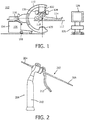
- FIG. 1 is a schematically illustration of a system 102 comprising an X ray device 104 for providing X ray images of a patient's interior.
- the X ray device 104 has a base frame 106 supported by wheels 108, a movable C arm 110 and a patient's table 112 for supporting a patient 114.
- the patient 114 is a human being, but may also be an animal.
- the C arm 110 is rotatable with regard to a first axis 116, which axis has a direction corresponding to a main orientation of the surgical table 112, and to a second axis 118, which second axis is perpendicular to the first axis and parallel to the patient's table 112.
- An X ray source 120 and an X ray detector 122 which is preferably a rectangular and flat detector, are mounted on the C arm 110 such that the X ray source and the X ray detector reside opposite one another along the axis 118.
- a camera 124 for providing a stream of video images of a patient's exterior is mounted on the C arm 110 aside the X ray detector 122, wherein the camera 124 may be responsive for example to a first range of wavelengths in the visible spectrum.
- a further camera 130 for providing a further stream of camera images of the patient's exterior may be additionally mounted on the C arm 110 aside the X ray detector 122, wherein the further camera 130 may be responsive to other wavelengths, for example to another range of wavelengths in the visible spectrum. Additionally and/or alternatively, the cameras 124 and 130 may be utilized for tracking a tracer plate at a device being in the field of view of the cameras.
- the system further comprises a processing unit 126 and a monitor 128 for visualizing information, wherein the processing unit may be connected, on the one hand, with the X-ray device so that the processing unit may control a generation of X-ray images, and on the other hand, with the cameras 124 and 130 for controlling and receiving images from the cameras and/or for tracking a device.
- the processing unit may further be connected to a data base, wherein the processing unit may receive from the data base previously generated X-ray data as well as spectral information of specific tissues for comparison with spectra sensed during an insertion of a device into tissue.
- Fig. 2 shows an embodiment of a device which may be inserted into tissue in a region of interest.
- the device is a K-wire 202 with a leading end portion 204 and a trailing end portion 206, wherein the leading end portion 204 may be provided with a sharp tip and/or a thread facilitating an inserting of the K-wire into hard tissue like bone.
- the K-wire 202 may be inserted by an instrument 208 having a grip portion 210 and a handle 212, wherein a movement of the handle 212 towards the grip portion may push the K-wire forwards, i.e. in a direction of the leading end portion.
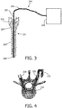
- Fig. 3 shows a pedicle screw 220 together with an optical sensing device 240.
- the pedicle screw 220 includes a body 222, a neck 224 and a head 226.
- the body 222 is provided with a thread having a pitch and an outer diameter and an inner diameter, such that the thread depth is the difference between the outer diameter and the inner diameter.
- the pedicle screw 220 has a hollow shaft, into which an optical probe or stylet 242 of the optical sensing device 240 may be inserted such that the optical probe or stylet 242 extends to the distal tip 228 of the screw 220.
- the stylet 242 and the whole optical sensing device 240 contain a waveguide such as an optical fiber 244 that is connected to an optical console 246 that is capable of sending and receiving light.
- the received light is spectrally analyzed allowing tissue discrimination at the tip of the screw 220. For instance techniques like diffuse reflectance spectroscopy, fluorescence spectroscopy, RAMAN spectroscopy, OCT can be applied.
- the received light is used for a determination of the parameter indicative for, for example, the fat content of tissue in front of the tip of the screw 220 and the optical stylet 242, which, in turn, is used for determining whether the tissue, in case of a bone, is that of the soft(er) part of the bone or that of the hard(er) part of the bone, thereby allowing for a navigation assistance in placing the screw 220 in a bone.
- the optical console 246 may be connected with the processing unit 126 of the system shown in fig. 1 , so that also the information provided by the optical console may be processed by the processing unit and may be combined with the information received from other parts of the system like the X-ray device or a tracking device.
- Fig. 4 shows two pedicle screws 220 placed in a vertebra 300 together with a tool 230 for screwing in the screws 220 into the bone.
- a screw insertion placement software and screw placement may show the vertebrae and a planned insertion line. Additionally and/or alternatively, the screw insertion placement may be shown guided by the cameras. The planned trajectory may be shown too and the position of the screw may be shown based on the navigation system. It is noted that an inside of a body may be shown based on an earlier taken image of the interior of the body, wherein the actual position of the vertebra may be different due to displacement of interior structures of the body compared to outer surface of the body.
- Fig. 5 an example of a model is illustrated, the model showing tissue structures that can be encountered during an insertion of a device.
- the device 250 should be in the vertebra 300 with the tip 252 in the cancellous bone 302.
- This cancellous bone has a higher fat content. Therefore for instance building a look up table based on the fat content of tissue can be used to guide the device placement.
- the fat content is a parameter that can be determined real-time with spectral tissue sensing 248. From the predicted fat content based on the device placement planning software and comparing this to the actual fat content based on the real-time determined fat content based on spectral tissue sensing is a way to determine the difference.
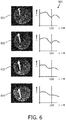
- Fig. 6 depicts four images 601, 602, 603, 604 from a sequence acquired during a screw insertion along with an example of acquired tissue measurements.
- images 601, 602 the screw tip can be observed to be positioned in cancellous bone have a higher fat content while in images 603, 604, the screw tip is positioned in cortial bone where the fat content is lower.
- the screw tip When according to the position determined by the imaging/navigation system the screw tip should be in cortical bone while the spectral tissue analysis carried out by the sensing system does not confirm this the screw is regarded as being off track and a corresponding signal may be generated.
- the spectral tissue analysis carried out by the sensing system does not confirm this the screw is regarded as being off track and a corresponding signal may be generated.
- Other parameters can be used as well for this. For instance, scattering may also reveal also a clear transition from cancellous to cortical bone that can be used as well.
- parts of the spectrum of received light reflected by tissue surrounding the screw tip are represented in the graphs 605 at the right-hand side of the images 601, 602, 603, 604.
- a wavelength (lambda) is represented in nanometer (nm)
- an intensity (I) is represented in arbitrary units.
- images 601 and 602 the relatively high fat content of the cancellous bone tissue in the vertebral body translates to a relatively pronounced minimum in the spectrum of the reflect light around a wavelength of 1200 nm.
- the processing unit 126 may transform the spectra measured by the light detector into physiological parameters that are indicative of the tissue state for the source-detector fiber combination. To determine whether a certain tissue is in front of the probe (or implantable device), the signal for the source-detector pair can be compared with a look-up-table. Another way is to translate the measured parameters into physiological parameters and define ranges for these parameters for each tissue type.
- Duck, F. A. “Physical properties of tissue: A 30 comprehensive reference book” (1990, Academic Press, Harcourt Brace Jovanovich, Publishers ), where methods based on classification and regression tree (CART) analyses are described for classifying tissue based on these physiological parameters.
- spectra from a given tissue type tend to look similar.
- the respective tissue "fingerprint" characteristic spectrum
- the fingerprint (for example by fitting the concentration of characteristic chromophores or by calculating principal components) is firstly extracted/enhanced and then these derived features are used to discriminate tissues based on typical machine learning methods such as SVM, CART, cut-off values, or k-nearest-neighbors.
- SVM SVM
- CART cut-off values
- k-nearest-neighbors k-nearest-neighbors.
- fat spectra have a different characteristic shape (or fingerprint) than the muscle or bone tissue. For example, a dip in the reflected light intensity near a wavelength of 1200 nm is nearly always more pronounced for tissue with a relatively high fat content than for muscle or cortial bone tissue (cf. right column graphs 605 in Fig. 6 ).
- An algorithm may be utilized to produce a table of tissue properties that may be encountered during the planned screw insertion.
- tissue properties two approaches can be used: First, the vertebra of the spine may be segmented using a segmentation algorithm. An anatomical model (for example a model as shown in fig. 5 ) may be applied to the segmented spine and may be used to calculate the expected spectral tissue measurements.
- an imaging technique may be used that can measure fat content or other tissue properties that can be detected with spectral tissue sensing. The imaging technique may be acquired before the procedure such as a pre-operative MRI which is consequently registered to the navigation system. Subsequently, one or more image series may be used as input for an algorithm that calculates the expected spectral tissue measurements. These image series can be multiple contrasts from MRI of the same anatomy or the combination of multiple imaging modalities. Also MR spectrographic imaging can be used as input. It will be understood that the two approaches could be combined.
- a method i.e. a software solution is described.
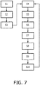
- the flowchart in fig. 7 illustrates the principles of position determination in accordance with an embodiment. It will be understood that the steps described with respect to the computer based method are major steps, wherein these major steps might be differentiated or divided into several sub steps. Furthermore, there might be also sub steps between these major steps. A sub step is only mentioned if that step is important for the understanding of the principles of the method according to the invention.
- step S1 information of a region of interest including different tissue types are received by the processing unit.
- Such information may be received from a data base storing previously generated images and/or from an imaging device generating the information/data immediately before the receiving.
- step S2 an input is received identifying a path through the region of interest.
- Such an input may be done by a user by means of a touch screen, a computer mouse or a keyboard, by an indication directly in an image and/or by defining coordinates. Additionally and/or alternatively, the input may be generated automatically by the processing unit based on comparable procedures, i.e. the processing unit may suggest a path through the tissue. The user may then just individually adjust the path as needed.
- step S3 a sequence of tissue types along the path is determined.
- the sequence of steps S1 to S3 may be considered as a planning method.
- step S4 optical information are received from the optical sensing means at the tip of the device, during an insertion of the device along the determined path into the region of interest.
- This step may comprise the sub-steps of emitting light, receiving light and determining a light spectrum.
- step S5 a tissue type at that distal end of the optical guide is determined based on the received optical information.
- step S6 the tissue type as determined in step S5 is compared with the predetermined tissue types on the path (as determined in step S3).
- the distal end of the optical guide may be traced by means of a tracking device in step S7.
- a spatial position and orientation of a proximal, i.e. trailling end of the optical guide may be traced, for example by a camera imaging a tracer plate.
- the known geometry of the optical guide together with the determined proximal position and orientation allows for a determination of the distal end, even if that end is currently not visible.
- step S8 possible positions of the distal end of the optical guide on its path through the tissues are determined based on a comparison of tissue types and/or on the tracked position. Based on that determination, a signal can be generated indicative for the possible positions in step S9.
- a visualization of the region of interest together with a virtual representation of an element to be inserted in the region of interest may be generated in step S10, wherein the distal end of the virtual representation of the element is shown at the most probable position on the path in an image which may be generated previously, i.e. during a planning phase of the procedure.
- steps S4 to S10 may be repeated, if necessary, for controlling an insertion of a device into a region of interest. It is noted that the advantage achieved by such a method can also be seen in a reduction of an X-ray exposure for a patient, as the controlling of the position of the inserted device is not primarily based on X-ray information.
- tissue sensing is not only relevant for screw insertions, but for many other clinical procedures as well.
- biopsies deep brain stimulation placement, tumor ablation etc.
- Tissue sensing hardware can be envisaged for typical devices used in these procedures.
- advanced imaging and/or anatomical modelling it is possible to calculate expected spectral tissue measurements for most anatomical regions.
- pedicle screw insertions in the cervical, thoracic and lumbar spine (ii) fracture fixations in various bone traumas, and (iii) plate positioning in hip and knee arthroplasties.
Landscapes
- Health & Medical Sciences (AREA)
- Life Sciences & Earth Sciences (AREA)
- Surgery (AREA)
- Engineering & Computer Science (AREA)
- Orthopedic Medicine & Surgery (AREA)
- Nuclear Medicine, Radiotherapy & Molecular Imaging (AREA)
- Public Health (AREA)
- Animal Behavior & Ethology (AREA)
- General Health & Medical Sciences (AREA)
- Biomedical Technology (AREA)
- Heart & Thoracic Surgery (AREA)
- Medical Informatics (AREA)
- Molecular Biology (AREA)
- Veterinary Medicine (AREA)
- Neurology (AREA)
- Robotics (AREA)
- Pathology (AREA)
- Radiology & Medical Imaging (AREA)
- Physics & Mathematics (AREA)
- Biophysics (AREA)
- Gynecology & Obstetrics (AREA)
- Oral & Maxillofacial Surgery (AREA)
- Apparatus For Radiation Diagnosis (AREA)
- Magnetic Resonance Imaging Apparatus (AREA)
- Investigating Or Analysing Materials By Optical Means (AREA)
- Surgical Instruments (AREA)
Applications Claiming Priority (2)
| Application Number | Priority Date | Filing Date | Title |
|---|---|---|---|
| EP17155320 | 2017-02-09 | ||
| PCT/EP2018/052989 WO2018146112A1 (en) | 2017-02-09 | 2018-02-07 | Position detection based on tissue discrimination |
Publications (2)
| Publication Number | Publication Date |
|---|---|
| EP3579781A1 EP3579781A1 (en) | 2019-12-18 |
| EP3579781B1 true EP3579781B1 (en) | 2020-07-15 |
Family
ID=58094176
Family Applications (1)
| Application Number | Title | Priority Date | Filing Date |
|---|---|---|---|
| EP18706662.6A Active EP3579781B1 (en) | 2017-02-09 | 2018-02-07 | Position detection based on tissue discrimination |
Country Status (5)
| Country | Link |
|---|---|
| US (2) | US11497562B2 (zh) |
| EP (1) | EP3579781B1 (zh) |
| JP (1) | JP7242537B2 (zh) |
| CN (1) | CN110381875B (zh) |
| WO (1) | WO2018146112A1 (zh) |
Families Citing this family (2)
| Publication number | Priority date | Publication date | Assignee | Title |
|---|---|---|---|---|
| CN117885097A (zh) * | 2017-03-07 | 2024-04-16 | 直观外科手术操作公司 | 用于控制具有可铰接远侧部分的工具的系统和方法 |
| EP3932357A1 (en) * | 2020-07-01 | 2022-01-05 | Koninklijke Philips N.V. | System for assisting a user in placing a penetrating device in tissue |
Family Cites Families (21)
| Publication number | Priority date | Publication date | Assignee | Title |
|---|---|---|---|---|
| US6470207B1 (en) * | 1999-03-23 | 2002-10-22 | Surgical Navigation Technologies, Inc. | Navigational guidance via computer-assisted fluoroscopic imaging |
| CA2404923A1 (en) * | 2000-03-31 | 2001-10-11 | Rita Medical Systems, Inc. | Tissue biopsy and treatment apparatus and method |
| WO2004051579A2 (en) * | 2002-12-04 | 2004-06-17 | Philips Intellectual Property & Standards Gmbh | Apparatus and method for assisting the navigation of a catheter in a vessel |
| US8092455B2 (en) | 2005-02-07 | 2012-01-10 | Warsaw Orthopedic, Inc. | Device and method for operating a tool relative to bone tissue and detecting neural elements |
| US9204830B2 (en) * | 2005-04-15 | 2015-12-08 | Surgisense Corporation | Surgical instruments with sensors for detecting tissue properties, and system using such instruments |
| US8249696B2 (en) | 2007-12-19 | 2012-08-21 | Depuy Spine, Inc. | Smart pedicle tool |
| WO2009111387A1 (en) * | 2008-03-03 | 2009-09-11 | Biospinex, Llc | Methods and devices for in situ tissue navigation |
| CN106943153B (zh) | 2008-12-11 | 2021-01-22 | 皇家飞利浦电子股份有限公司 | 用于产生患者内部和外部图像的系统和方法 |
| US8366719B2 (en) | 2009-03-18 | 2013-02-05 | Integrated Spinal Concepts, Inc. | Image-guided minimal-step placement of screw into bone |
| CN102448366B (zh) * | 2009-05-28 | 2014-06-25 | 皇家飞利浦电子股份有限公司 | 使用针设备在介入期间重新校准预先记录的图像 |
| KR101759534B1 (ko) * | 2009-10-30 | 2017-07-19 | 더 존스 홉킨스 유니버시티 | 외과 수술 시 임상적으로 중요한 해부상의 랜드마크에 대한 시각 추적 및 주석 달기 |
| US20110196376A1 (en) * | 2010-02-09 | 2011-08-11 | Burak Ozgur | Osteo-navigation |
| CN103917155B (zh) * | 2011-11-07 | 2017-02-15 | 皇家飞利浦有限公司 | 用于确定组织状态的检测装置 |
| RU2014142631A (ru) * | 2012-03-23 | 2016-05-20 | Конинклейке Филипс Н.В. | Фотонная система иглы с временами интеграции измерения, зависящими от скорости смещения иглы |
| RU2014143065A (ru) * | 2012-03-27 | 2016-05-20 | Конинклейке Филипс Н.В. | Оптическая обратная связь с задержкой на интеграцию при наведении изображения |
| JP2015516194A (ja) * | 2012-03-29 | 2015-06-11 | コーニンクレッカ フィリップス エヌ ヴェ | 個々のピクセルもしくはボクセルに組織固有のpet減衰値を割り当てるmri方法 |
| US9204841B2 (en) | 2012-12-31 | 2015-12-08 | Biosense Webster (Israel) Ltd. | Catheter with serially connected sensing structures and methods of calibration and detection |
| US20140276200A1 (en) * | 2013-03-15 | 2014-09-18 | Covidien Lp | Microwave energy-delivery device and system |
| US20160081712A1 (en) * | 2013-04-29 | 2016-03-24 | The Charltte-Mecklenburg Hospital Authority D/B/A Carolinas Healthcare System | Device, system, and method for insertion of a medical device into a subject |
| JP6533078B2 (ja) | 2015-03-20 | 2019-06-19 | テルモ株式会社 | 画像診断装置、その制御方法、プログラム及びコンピュータ可読記憶媒体 |
| US10973587B2 (en) * | 2015-08-19 | 2021-04-13 | Brainlab Ag | Reference array holder |
-
2018
- 2018-02-07 CN CN201880011150.9A patent/CN110381875B/zh active Active
- 2018-02-07 EP EP18706662.6A patent/EP3579781B1/en active Active
- 2018-02-07 WO PCT/EP2018/052989 patent/WO2018146112A1/en unknown
- 2018-02-07 JP JP2019542687A patent/JP7242537B2/ja active Active
- 2018-02-07 US US16/483,951 patent/US11497562B2/en active Active
-
2022
- 2022-06-24 US US17/848,490 patent/US11712310B2/en active Active
Non-Patent Citations (1)
| Title |
|---|
| None * |
Also Published As
| Publication number | Publication date |
|---|---|
| CN110381875A (zh) | 2019-10-25 |
| US11712310B2 (en) | 2023-08-01 |
| JP2020508097A (ja) | 2020-03-19 |
| JP7242537B2 (ja) | 2023-03-20 |
| EP3579781A1 (en) | 2019-12-18 |
| WO2018146112A1 (en) | 2018-08-16 |
| US20200085506A1 (en) | 2020-03-19 |
| US20220313368A1 (en) | 2022-10-06 |
| US11497562B2 (en) | 2022-11-15 |
| CN110381875B (zh) | 2023-03-21 |
Similar Documents
| Publication | Publication Date | Title |
|---|---|---|
| Helm et al. | Spinal navigation and imaging: history, trends, and future | |
| JP5121401B2 (ja) | 埋植物距離測定のシステム | |
| US11712310B2 (en) | Position detection based on tissue discrimination | |
| JP5328137B2 (ja) | 用具又は埋植物の表現を表示するユーザ・インタフェイス・システム | |
| US20230301726A1 (en) | Systems, instruments and methods for surgical navigation with verification feedback | |
| CN110769770A (zh) | 两自由度系统和用于脊部应用的方法 | |
| Bledsoe et al. | Accuracy of upper thoracic pedicle screw placement using three-dimensional image guidance | |
| US12004818B2 (en) | System and method for performing and evaluating a procedure | |
| CN114846517A (zh) | 确定2d医学图像中的对象之间的相对3d位置和取向 | |
| JP2007518521A (ja) | 低侵襲性の切開口のためのシステムおよび方法 | |
| Wallace et al. | Computer-assisted navigation in complex cervical spine surgery: tips and tricks | |
| Guevar et al. | Accuracy and safety of neuronavigation for minimally invasive stabilization in the thoracolumbar spine using polyaxial screws-rod: a canine cadaveric proof of concept | |
| US20110196376A1 (en) | Osteo-navigation | |
| TWM570117U (zh) | 用於椎弓根螺釘微創定位的擴增實境裝置 | |
| CN118436438A (zh) | 用于将切口标记投射到患者上的方法和系统 | |
| US7340291B2 (en) | Medical apparatus for tracking movement of a bone fragment in a displayed image | |
| Sklar et al. | First case report using optical topographic-guided navigation in revision spinal fusion for calcified thoracic disk | |
| TWI671763B (zh) | 用於椎弓根螺釘微創定位的擴增實境裝置 | |
| Sembrano et al. | Percutaneous pedicle screws | |
| Swartman et al. | Intraoperative 3D Imaging of the Pelvic Ring | |
| Li et al. | EM-based Navigation-Guided Percutaneous Endoscopic Lumbar Foraminoplasty | |
| WO2021213967A1 (en) | Orthopedic pin for optically analyzing a bone region | |
| CN112842528A (zh) | 两自由度系统和方法 | |
| Sembrano et al. | Percutaneous Lumbar Pedicle Screw Insertion | |
| Lefkowitz et al. | Computer-assisted image-guided fluoroscopy (virtual fluoroscopy) |
Legal Events
| Date | Code | Title | Description |
|---|---|---|---|
| STAA | Information on the status of an ep patent application or granted ep patent |
Free format text: STATUS: UNKNOWN |
|
| STAA | Information on the status of an ep patent application or granted ep patent |
Free format text: STATUS: THE INTERNATIONAL PUBLICATION HAS BEEN MADE |
|
| PUAI | Public reference made under article 153(3) epc to a published international application that has entered the european phase |
Free format text: ORIGINAL CODE: 0009012 |
|
| STAA | Information on the status of an ep patent application or granted ep patent |
Free format text: STATUS: REQUEST FOR EXAMINATION WAS MADE |
|
| 17P | Request for examination filed |
Effective date: 20190909 |
|
| AK | Designated contracting states |
Kind code of ref document: A1 Designated state(s): AL AT BE BG CH CY CZ DE DK EE ES FI FR GB GR HR HU IE IS IT LI LT LU LV MC MK MT NL NO PL PT RO RS SE SI SK SM TR |
|
| AX | Request for extension of the european patent |
Extension state: BA ME |
|
| GRAP | Despatch of communication of intention to grant a patent |
Free format text: ORIGINAL CODE: EPIDOSNIGR1 |
|
| STAA | Information on the status of an ep patent application or granted ep patent |
Free format text: STATUS: GRANT OF PATENT IS INTENDED |
|
| RAP1 | Party data changed (applicant data changed or rights of an application transferred) |
Owner name: KONINKLIJKE PHILIPS N.V. |
|
| DAV | Request for validation of the european patent (deleted) | ||
| DAX | Request for extension of the european patent (deleted) | ||
| INTG | Intention to grant announced |
Effective date: 20200226 |
|
| GRAS | Grant fee paid |
Free format text: ORIGINAL CODE: EPIDOSNIGR3 |
|
| GRAA | (expected) grant |
Free format text: ORIGINAL CODE: 0009210 |
|
| STAA | Information on the status of an ep patent application or granted ep patent |
Free format text: STATUS: THE PATENT HAS BEEN GRANTED |
|
| AK | Designated contracting states |
Kind code of ref document: B1 Designated state(s): AL AT BE BG CH CY CZ DE DK EE ES FI FR GB GR HR HU IE IS IT LI LT LU LV MC MK MT NL NO PL PT RO RS SE SI SK SM TR |
|
| REG | Reference to a national code |
Ref country code: GB Ref legal event code: FG4D Ref country code: CH Ref legal event code: EP |
|
| REG | Reference to a national code |
Ref country code: IE Ref legal event code: FG4D |
|
| REG | Reference to a national code |
Ref country code: DE Ref legal event code: R096 Ref document number: 602018006102 Country of ref document: DE |
|
| REG | Reference to a national code |
Ref country code: AT Ref legal event code: REF Ref document number: 1290116 Country of ref document: AT Kind code of ref document: T Effective date: 20200815 |
|
| REG | Reference to a national code |
Ref country code: LT Ref legal event code: MG4D |
|
| REG | Reference to a national code |
Ref country code: AT Ref legal event code: MK05 Ref document number: 1290116 Country of ref document: AT Kind code of ref document: T Effective date: 20200715 |
|
| REG | Reference to a national code |
Ref country code: NL Ref legal event code: MP Effective date: 20200715 |
|
| PG25 | Lapsed in a contracting state [announced via postgrant information from national office to epo] |
Ref country code: BG Free format text: LAPSE BECAUSE OF FAILURE TO SUBMIT A TRANSLATION OF THE DESCRIPTION OR TO PAY THE FEE WITHIN THE PRESCRIBED TIME-LIMIT Effective date: 20201015 Ref country code: PT Free format text: LAPSE BECAUSE OF FAILURE TO SUBMIT A TRANSLATION OF THE DESCRIPTION OR TO PAY THE FEE WITHIN THE PRESCRIBED TIME-LIMIT Effective date: 20201116 Ref country code: ES Free format text: LAPSE BECAUSE OF FAILURE TO SUBMIT A TRANSLATION OF THE DESCRIPTION OR TO PAY THE FEE WITHIN THE PRESCRIBED TIME-LIMIT Effective date: 20200715 Ref country code: AT Free format text: LAPSE BECAUSE OF FAILURE TO SUBMIT A TRANSLATION OF THE DESCRIPTION OR TO PAY THE FEE WITHIN THE PRESCRIBED TIME-LIMIT Effective date: 20200715 Ref country code: HR Free format text: LAPSE BECAUSE OF FAILURE TO SUBMIT A TRANSLATION OF THE DESCRIPTION OR TO PAY THE FEE WITHIN THE PRESCRIBED TIME-LIMIT Effective date: 20200715 Ref country code: LT Free format text: LAPSE BECAUSE OF FAILURE TO SUBMIT A TRANSLATION OF THE DESCRIPTION OR TO PAY THE FEE WITHIN THE PRESCRIBED TIME-LIMIT Effective date: 20200715 Ref country code: SE Free format text: LAPSE BECAUSE OF FAILURE TO SUBMIT A TRANSLATION OF THE DESCRIPTION OR TO PAY THE FEE WITHIN THE PRESCRIBED TIME-LIMIT Effective date: 20200715 Ref country code: FI Free format text: LAPSE BECAUSE OF FAILURE TO SUBMIT A TRANSLATION OF THE DESCRIPTION OR TO PAY THE FEE WITHIN THE PRESCRIBED TIME-LIMIT Effective date: 20200715 Ref country code: GR Free format text: LAPSE BECAUSE OF FAILURE TO SUBMIT A TRANSLATION OF THE DESCRIPTION OR TO PAY THE FEE WITHIN THE PRESCRIBED TIME-LIMIT Effective date: 20201016 Ref country code: NO Free format text: LAPSE BECAUSE OF FAILURE TO SUBMIT A TRANSLATION OF THE DESCRIPTION OR TO PAY THE FEE WITHIN THE PRESCRIBED TIME-LIMIT Effective date: 20201015 |
|
| PG25 | Lapsed in a contracting state [announced via postgrant information from national office to epo] |
Ref country code: IS Free format text: LAPSE BECAUSE OF FAILURE TO SUBMIT A TRANSLATION OF THE DESCRIPTION OR TO PAY THE FEE WITHIN THE PRESCRIBED TIME-LIMIT Effective date: 20201115 Ref country code: LV Free format text: LAPSE BECAUSE OF FAILURE TO SUBMIT A TRANSLATION OF THE DESCRIPTION OR TO PAY THE FEE WITHIN THE PRESCRIBED TIME-LIMIT Effective date: 20200715 Ref country code: PL Free format text: LAPSE BECAUSE OF FAILURE TO SUBMIT A TRANSLATION OF THE DESCRIPTION OR TO PAY THE FEE WITHIN THE PRESCRIBED TIME-LIMIT Effective date: 20200715 Ref country code: RS Free format text: LAPSE BECAUSE OF FAILURE TO SUBMIT A TRANSLATION OF THE DESCRIPTION OR TO PAY THE FEE WITHIN THE PRESCRIBED TIME-LIMIT Effective date: 20200715 |
|
| PG25 | Lapsed in a contracting state [announced via postgrant information from national office to epo] |
Ref country code: NL Free format text: LAPSE BECAUSE OF FAILURE TO SUBMIT A TRANSLATION OF THE DESCRIPTION OR TO PAY THE FEE WITHIN THE PRESCRIBED TIME-LIMIT Effective date: 20200715 |
|
| REG | Reference to a national code |
Ref country code: DE Ref legal event code: R097 Ref document number: 602018006102 Country of ref document: DE |
|
| PG25 | Lapsed in a contracting state [announced via postgrant information from national office to epo] |
Ref country code: EE Free format text: LAPSE BECAUSE OF FAILURE TO SUBMIT A TRANSLATION OF THE DESCRIPTION OR TO PAY THE FEE WITHIN THE PRESCRIBED TIME-LIMIT Effective date: 20200715 Ref country code: DK Free format text: LAPSE BECAUSE OF FAILURE TO SUBMIT A TRANSLATION OF THE DESCRIPTION OR TO PAY THE FEE WITHIN THE PRESCRIBED TIME-LIMIT Effective date: 20200715 Ref country code: CZ Free format text: LAPSE BECAUSE OF FAILURE TO SUBMIT A TRANSLATION OF THE DESCRIPTION OR TO PAY THE FEE WITHIN THE PRESCRIBED TIME-LIMIT Effective date: 20200715 Ref country code: RO Free format text: LAPSE BECAUSE OF FAILURE TO SUBMIT A TRANSLATION OF THE DESCRIPTION OR TO PAY THE FEE WITHIN THE PRESCRIBED TIME-LIMIT Effective date: 20200715 Ref country code: SM Free format text: LAPSE BECAUSE OF FAILURE TO SUBMIT A TRANSLATION OF THE DESCRIPTION OR TO PAY THE FEE WITHIN THE PRESCRIBED TIME-LIMIT Effective date: 20200715 Ref country code: IT Free format text: LAPSE BECAUSE OF FAILURE TO SUBMIT A TRANSLATION OF THE DESCRIPTION OR TO PAY THE FEE WITHIN THE PRESCRIBED TIME-LIMIT Effective date: 20200715 |
|
| PLBE | No opposition filed within time limit |
Free format text: ORIGINAL CODE: 0009261 |
|
| STAA | Information on the status of an ep patent application or granted ep patent |
Free format text: STATUS: NO OPPOSITION FILED WITHIN TIME LIMIT |
|
| PG25 | Lapsed in a contracting state [announced via postgrant information from national office to epo] |
Ref country code: AL Free format text: LAPSE BECAUSE OF FAILURE TO SUBMIT A TRANSLATION OF THE DESCRIPTION OR TO PAY THE FEE WITHIN THE PRESCRIBED TIME-LIMIT Effective date: 20200715 |
|
| 26N | No opposition filed |
Effective date: 20210416 |
|
| PG25 | Lapsed in a contracting state [announced via postgrant information from national office to epo] |
Ref country code: SK Free format text: LAPSE BECAUSE OF FAILURE TO SUBMIT A TRANSLATION OF THE DESCRIPTION OR TO PAY THE FEE WITHIN THE PRESCRIBED TIME-LIMIT Effective date: 20200715 |
|
| PG25 | Lapsed in a contracting state [announced via postgrant information from national office to epo] |
Ref country code: MC Free format text: LAPSE BECAUSE OF FAILURE TO SUBMIT A TRANSLATION OF THE DESCRIPTION OR TO PAY THE FEE WITHIN THE PRESCRIBED TIME-LIMIT Effective date: 20200715 |
|
| REG | Reference to a national code |
Ref country code: BE Ref legal event code: MM Effective date: 20210228 |
|
| PG25 | Lapsed in a contracting state [announced via postgrant information from national office to epo] |
Ref country code: LU Free format text: LAPSE BECAUSE OF NON-PAYMENT OF DUE FEES Effective date: 20210207 Ref country code: LI Free format text: LAPSE BECAUSE OF NON-PAYMENT OF DUE FEES Effective date: 20210228 Ref country code: CH Free format text: LAPSE BECAUSE OF NON-PAYMENT OF DUE FEES Effective date: 20210228 |
|
| PG25 | Lapsed in a contracting state [announced via postgrant information from national office to epo] |
Ref country code: IE Free format text: LAPSE BECAUSE OF NON-PAYMENT OF DUE FEES Effective date: 20210207 |
|
| PG25 | Lapsed in a contracting state [announced via postgrant information from national office to epo] |
Ref country code: BE Free format text: LAPSE BECAUSE OF NON-PAYMENT OF DUE FEES Effective date: 20210228 |
|
| PG25 | Lapsed in a contracting state [announced via postgrant information from national office to epo] |
Ref country code: CY Free format text: LAPSE BECAUSE OF FAILURE TO SUBMIT A TRANSLATION OF THE DESCRIPTION OR TO PAY THE FEE WITHIN THE PRESCRIBED TIME-LIMIT Effective date: 20200715 |
|
| PG25 | Lapsed in a contracting state [announced via postgrant information from national office to epo] |
Ref country code: HU Free format text: LAPSE BECAUSE OF FAILURE TO SUBMIT A TRANSLATION OF THE DESCRIPTION OR TO PAY THE FEE WITHIN THE PRESCRIBED TIME-LIMIT; INVALID AB INITIO Effective date: 20180207 |
|
| PG25 | Lapsed in a contracting state [announced via postgrant information from national office to epo] |
Ref country code: SI Free format text: LAPSE BECAUSE OF FAILURE TO SUBMIT A TRANSLATION OF THE DESCRIPTION OR TO PAY THE FEE WITHIN THE PRESCRIBED TIME-LIMIT Effective date: 20200715 |
|
| PG25 | Lapsed in a contracting state [announced via postgrant information from national office to epo] |
Ref country code: MK Free format text: LAPSE BECAUSE OF FAILURE TO SUBMIT A TRANSLATION OF THE DESCRIPTION OR TO PAY THE FEE WITHIN THE PRESCRIBED TIME-LIMIT Effective date: 20200715 |
|
| PGFP | Annual fee paid to national office [announced via postgrant information from national office to epo] |
Ref country code: DE Payment date: 20240228 Year of fee payment: 7 Ref country code: GB Payment date: 20240220 Year of fee payment: 7 |
|
| PGFP | Annual fee paid to national office [announced via postgrant information from national office to epo] |
Ref country code: FR Payment date: 20240226 Year of fee payment: 7 |
|
| PG25 | Lapsed in a contracting state [announced via postgrant information from national office to epo] |
Ref country code: MT Free format text: LAPSE BECAUSE OF FAILURE TO SUBMIT A TRANSLATION OF THE DESCRIPTION OR TO PAY THE FEE WITHIN THE PRESCRIBED TIME-LIMIT Effective date: 20200715 |