EP3579732B1 - Überwachungssystem für spender - Google Patents
Überwachungssystem für spender Download PDFInfo
- Publication number
- EP3579732B1 EP3579732B1 EP18766752.2A EP18766752A EP3579732B1 EP 3579732 B1 EP3579732 B1 EP 3579732B1 EP 18766752 A EP18766752 A EP 18766752A EP 3579732 B1 EP3579732 B1 EP 3579732B1
- Authority
- EP
- European Patent Office
- Prior art keywords
- sheet material
- supply
- dispenser
- feed roller
- rotation
- Prior art date
- Legal status (The legal status is an assumption and is not a legal conclusion. Google has not performed a legal analysis and makes no representation as to the accuracy of the status listed.)
- Active
Links
Images


Classifications
-
- A—HUMAN NECESSITIES
- A47—FURNITURE; DOMESTIC ARTICLES OR APPLIANCES; COFFEE MILLS; SPICE MILLS; SUCTION CLEANERS IN GENERAL
- A47K—SANITARY EQUIPMENT; ACCESSORIES THEREFOR, e.g. TOILET ACCESSORIES
- A47K10/00—Body-drying implements; Toilet paper; Holders therefor
- A47K10/24—Towel dispensers; Toilet paper dispensers
- A47K10/32—Dispensers for paper towels or toilet paper
- A47K10/34—Dispensers for paper towels or toilet paper dispensing from a web, e.g. with mechanical dispensing means
- A47K10/36—Dispensers for paper towels or toilet paper dispensing from a web, e.g. with mechanical dispensing means with mechanical dispensing, roll switching or cutting devices
- A47K10/3656—Dispensers for paper towels or toilet paper dispensing from a web, e.g. with mechanical dispensing means with mechanical dispensing, roll switching or cutting devices with paper jam preventing devices
-
- A—HUMAN NECESSITIES
- A47—FURNITURE; DOMESTIC ARTICLES OR APPLIANCES; COFFEE MILLS; SPICE MILLS; SUCTION CLEANERS IN GENERAL
- A47K—SANITARY EQUIPMENT; ACCESSORIES THEREFOR, e.g. TOILET ACCESSORIES
- A47K10/00—Body-drying implements; Toilet paper; Holders therefor
- A47K10/24—Towel dispensers; Toilet paper dispensers
- A47K10/32—Dispensers for paper towels or toilet paper
- A47K10/34—Dispensers for paper towels or toilet paper dispensing from a web, e.g. with mechanical dispensing means
- A47K10/38—Dispensers for paper towels or toilet paper dispensing from a web, e.g. with mechanical dispensing means the web being rolled-up
-
- B—PERFORMING OPERATIONS; TRANSPORTING
- B65—CONVEYING; PACKING; STORING; HANDLING THIN OR FILAMENTARY MATERIAL
- B65H—HANDLING THIN OR FILAMENTARY MATERIAL, e.g. SHEETS, WEBS, CABLES
- B65H16/00—Unwinding, paying-out webs
- B65H16/005—Dispensers, i.e. machines for unwinding only parts of web roll
-
- B—PERFORMING OPERATIONS; TRANSPORTING
- B65—CONVEYING; PACKING; STORING; HANDLING THIN OR FILAMENTARY MATERIAL
- B65H—HANDLING THIN OR FILAMENTARY MATERIAL, e.g. SHEETS, WEBS, CABLES
- B65H26/00—Warning or safety devices, e.g. automatic fault detectors, stop-motions, for web-advancing mechanisms
- B65H26/06—Warning or safety devices, e.g. automatic fault detectors, stop-motions, for web-advancing mechanisms responsive to predetermined lengths of webs
-
- B—PERFORMING OPERATIONS; TRANSPORTING
- B65—CONVEYING; PACKING; STORING; HANDLING THIN OR FILAMENTARY MATERIAL
- B65H—HANDLING THIN OR FILAMENTARY MATERIAL, e.g. SHEETS, WEBS, CABLES
- B65H35/00—Delivering articles from cutting or line-perforating machines; Article or web delivery apparatus incorporating cutting or line-perforating devices, e.g. adhesive tape dispensers
- B65H35/0006—Article or web delivery apparatus incorporating cutting or line-perforating devices
- B65H35/006—Article or web delivery apparatus incorporating cutting or line-perforating devices with means for delivering a predetermined length of tape
-
- A—HUMAN NECESSITIES
- A47—FURNITURE; DOMESTIC ARTICLES OR APPLIANCES; COFFEE MILLS; SPICE MILLS; SUCTION CLEANERS IN GENERAL
- A47K—SANITARY EQUIPMENT; ACCESSORIES THEREFOR, e.g. TOILET ACCESSORIES
- A47K10/00—Body-drying implements; Toilet paper; Holders therefor
- A47K10/24—Towel dispensers; Toilet paper dispensers
- A47K10/32—Dispensers for paper towels or toilet paper
- A47K10/34—Dispensers for paper towels or toilet paper dispensing from a web, e.g. with mechanical dispensing means
- A47K10/36—Dispensers for paper towels or toilet paper dispensing from a web, e.g. with mechanical dispensing means with mechanical dispensing, roll switching or cutting devices
- A47K10/3606—The cutting devices being motor driven
- A47K10/3612—The cutting devices being motor driven with drive and pinch rollers
-
- A—HUMAN NECESSITIES
- A47—FURNITURE; DOMESTIC ARTICLES OR APPLIANCES; COFFEE MILLS; SPICE MILLS; SUCTION CLEANERS IN GENERAL
- A47K—SANITARY EQUIPMENT; ACCESSORIES THEREFOR, e.g. TOILET ACCESSORIES
- A47K10/00—Body-drying implements; Toilet paper; Holders therefor
- A47K10/24—Towel dispensers; Toilet paper dispensers
- A47K10/32—Dispensers for paper towels or toilet paper
- A47K10/34—Dispensers for paper towels or toilet paper dispensing from a web, e.g. with mechanical dispensing means
- A47K10/36—Dispensers for paper towels or toilet paper dispensing from a web, e.g. with mechanical dispensing means with mechanical dispensing, roll switching or cutting devices
- A47K10/3606—The cutting devices being motor driven
- A47K10/3625—The cutting devices being motor driven with electronic control means
-
- A—HUMAN NECESSITIES
- A47—FURNITURE; DOMESTIC ARTICLES OR APPLIANCES; COFFEE MILLS; SPICE MILLS; SUCTION CLEANERS IN GENERAL
- A47K—SANITARY EQUIPMENT; ACCESSORIES THEREFOR, e.g. TOILET ACCESSORIES
- A47K10/00—Body-drying implements; Toilet paper; Holders therefor
- A47K10/24—Towel dispensers; Toilet paper dispensers
- A47K10/32—Dispensers for paper towels or toilet paper
- A47K10/34—Dispensers for paper towels or toilet paper dispensing from a web, e.g. with mechanical dispensing means
- A47K10/36—Dispensers for paper towels or toilet paper dispensing from a web, e.g. with mechanical dispensing means with mechanical dispensing, roll switching or cutting devices
- A47K10/3687—Dispensers for paper towels or toilet paper dispensing from a web, e.g. with mechanical dispensing means with mechanical dispensing, roll switching or cutting devices with one or more reserve rolls
-
- A—HUMAN NECESSITIES
- A47—FURNITURE; DOMESTIC ARTICLES OR APPLIANCES; COFFEE MILLS; SPICE MILLS; SUCTION CLEANERS IN GENERAL
- A47K—SANITARY EQUIPMENT; ACCESSORIES THEREFOR, e.g. TOILET ACCESSORIES
- A47K10/00—Body-drying implements; Toilet paper; Holders therefor
- A47K10/24—Towel dispensers; Toilet paper dispensers
- A47K10/32—Dispensers for paper towels or toilet paper
- A47K2010/3226—Dispensers for paper towels or toilet paper collecting data of usage
-
- A—HUMAN NECESSITIES
- A47—FURNITURE; DOMESTIC ARTICLES OR APPLIANCES; COFFEE MILLS; SPICE MILLS; SUCTION CLEANERS IN GENERAL
- A47K—SANITARY EQUIPMENT; ACCESSORIES THEREFOR, e.g. TOILET ACCESSORIES
- A47K10/00—Body-drying implements; Toilet paper; Holders therefor
- A47K10/24—Towel dispensers; Toilet paper dispensers
- A47K10/32—Dispensers for paper towels or toilet paper
- A47K10/34—Dispensers for paper towels or toilet paper dispensing from a web, e.g. with mechanical dispensing means
- A47K10/36—Dispensers for paper towels or toilet paper dispensing from a web, e.g. with mechanical dispensing means with mechanical dispensing, roll switching or cutting devices
- A47K2010/3668—Detection of the presence of a user
-
- B—PERFORMING OPERATIONS; TRANSPORTING
- B65—CONVEYING; PACKING; STORING; HANDLING THIN OR FILAMENTARY MATERIAL
- B65H—HANDLING THIN OR FILAMENTARY MATERIAL, e.g. SHEETS, WEBS, CABLES
- B65H2404/00—Parts for transporting or guiding the handled material
- B65H2404/10—Rollers
- B65H2404/14—Roller pairs
- B65H2404/143—Roller pairs driving roller and idler roller arrangement
-
- B—PERFORMING OPERATIONS; TRANSPORTING
- B65—CONVEYING; PACKING; STORING; HANDLING THIN OR FILAMENTARY MATERIAL
- B65H—HANDLING THIN OR FILAMENTARY MATERIAL, e.g. SHEETS, WEBS, CABLES
- B65H2511/00—Dimensions; Position; Numbers; Identification; Occurrences
- B65H2511/10—Size; Dimensions
- B65H2511/11—Length
- B65H2511/114—Remaining length of web roll
-
- B—PERFORMING OPERATIONS; TRANSPORTING
- B65—CONVEYING; PACKING; STORING; HANDLING THIN OR FILAMENTARY MATERIAL
- B65H—HANDLING THIN OR FILAMENTARY MATERIAL, e.g. SHEETS, WEBS, CABLES
- B65H2553/00—Sensing or detecting means
- B65H2553/51—Encoders, e.g. linear
-
- B—PERFORMING OPERATIONS; TRANSPORTING
- B65—CONVEYING; PACKING; STORING; HANDLING THIN OR FILAMENTARY MATERIAL
- B65H—HANDLING THIN OR FILAMENTARY MATERIAL, e.g. SHEETS, WEBS, CABLES
- B65H2701/00—Handled material; Storage means
- B65H2701/10—Handled articles or webs
- B65H2701/19—Specific article or web
- B65H2701/1924—Napkins or tissues, e.g. dressings, toweling, serviettes, kitchen paper and compresses
Definitions
- the present disclosure is directed to dispensers for flexible sheet materials, and in particular, to a dispenser with a monitoring or sensing system for detection and monitoring of the amounts of sheet material dispensed by the dispenser to enable dynamic measurement of a remaining supply of the sheet material within the dispenser.
- Dispensers for sheet materials are commonly used in hospitals, restrooms and other facilities. When the supply of sheet material in such dispensers is running low or has been fully dispensed, it generally is not apparent until the dispenser is out of and no longer dispenses sheet material. Paper, measuring or metering systems have been used, but generally do not provide precise and/or continuous monitoring of the remaining supply of sheet material. For example, available sheet material metering systems or gauges can include a mechanical lever arm that engages the supply of sheet material and is moved as the sheet material is dispensed and reduces in diameter.
- the lever arm After the lever arm has moved a specific distance/amount, i.e., due to a reduction in the diameter of the sheet material, the lever arm will activate a switch that in turn can activate a light or other notification mechanism to indicate a low paper condition. Accordingly, typical paper metering systems often simply provide an indication as to whether the sheet material supply is out or is about to run out, and generally do not provide substantially precise, real-time monitoring of the amount of remaining sheet material.
- the specific amount of sheet material remaining cannot be discerned, e.g ., whether the dispenser is completely out of paper or if it still has some amount of sheet material remaining; which may result in replacement of the sheet material before complete dispensing thereof, leading to waste of the sheet material and increasing costs, or the dispenser being rendered inoperable until an empty supply roll is discovered and replaced.
- WO 2007/068270 A1 discloses a dispenser with a quantity measuring device and method of determining quantity of sheet material remaining.
- the present invention is directed to a dispenser according to claim 1 for dispensing sheet materials, such as towels, tissues or other paper products.
- the dispenser includes a housing, with a roll support mounted within the housing and rotatably supporting at least one supply of sheet material at least partially within the dispenser housing.
- the dispenser can include, a plurality of supplies of sheet material including, for example, at least one initially full/new roll or primary supply and at least one secondary or "stub roll".
- the dispenser housing further includes a driven feed roller rotatably mounted therein for feeding the sheet material from each supply roll along a feed or discharge path toward and through a discharge throat arranged along the dispenser housing.
- the feed roller is automatically driven by a drive system including a motor.
- the dispenser housing also may include one or more pressing rollers and/or guide rollers arranged along the feed path and adjacent the feed roller to guide the sheet material therebetween and toward the discharge throat.
- the dispenser includes a material supply monitoring and measurement system operable to continuously monitor and substantially dynamically determine a remaining amount of the supply of sheet material in the dispenser.
- the monitoring system includes a plurality of magnets disposed about the supply which can include a primary supply roll and a secondary or "stub" roll of sheet material, for example, along, or substantially adjacent one end of a core or supporting roll thereof, with the plurality of magnets being rotatable therewith during dispensing thereof.
- the monitoring system includes a plurality of magnets arranged along, or substantially adjacent to, at least one end of the supply (or supplies) of sheet material (e.g., on a hub or along a portion of the core or support roll for the supply or supplies), defining a magnetic ring.
- the magnets are also arranged such that adjacent magnets have opposite polarities, such that the polarities of the magnets alternate north, south, north, south.
- At least one sensor will be arranged substantially proximal or adjacent the series of magnets, and can include a reed switch, a hall element, proximity sensor, or other suitable sensor operable to measure or otherwise detect variations, fluctuations or other changes in a magnetic field generated as the magnet, or series of magnets, is rotated with the supply of sheet material during dispensing thereof and passes by the sensor.
- the detected variations, fluctuations or changes of the magnetic field can be correlated to number of rotations of the supply of sheet material and/or a rotation angle of the supply of sheet material for dispensing a desired length of the sheet material during each dispensing operation.
- a diameter of the supply of sheet material can be substantially dynamically determined during or following each dispensing operation and, based on this determined/monitored diameter, an amount of sheet material remaining in the dispenser can be dynamically determined by the monitoring system with substantial accuracy.
- sensing devices or mechanisms such as encoders or other detectors that can monitor and provide a measurement of the number of rotations of the motor/feed roller and/or extent of rotation of the supply of sheet material can be used, without departing from the scope of the present disclosure.
- the dispenser further includes controller in communication with the at least one sensor of the monitoring system so as to require signals corresponding to the dynamic measurements or readings obtained by the at least one sensor of the monitoring system will be communicated to the controller of the material supply and the feed roller/drive motor, which signals can be indicative of or can be used to determine the number rotations of the supply of sheet material (or the core or support roll thereof) as well as a number of rotations of the feed roller and/or motor driving the feed roller for each rotation of the supply of sheet material, as the sheet material is dispensed.
- the determined number of rotations of the supply of sheet material and the feed roller/motor further can be used by the controller to calculate or otherwise determine a diameter of the supply of sheet material based, at least in part, on a selected length of sheet material being dispensed by each operation of the dispenser.
- the number of rotations of the supply of sheet material, or the angular distance of the supply during such rotation needed to dispense the selected length of sheet material during each dispensing operation can be counted and/or updated after each operation to dynamically determine the remaining diameter of the supply of sheet material.
- This determined remaining diameter of the supply of sheet material can be compared to an initial and/or a final diameter of the sheet material (i.e.
- the monitoring system can provide for a substantially continuous, accurate, and precise monitoring of the amount of sheet material remaining in the dispenser, which dynamic or updated measurement further can be reported or communicated to an attendant or to provide notifications of, not only a low paper detection, but also an indication of the amount of paper remaining and/or a projection of when such remaining paper supply might run out.
- the monitoring system also can include a means for automatically determining the length of sheet material dispensed during each distribution of sheet material by an operator.
- the length of the sheet material dispensed can be determined based, at least in part, on the number of rotations and/or angle of the driven feed roller or its motor.
- a fixed length of sheet material i.e. , 15.24 cm (6"), 20,32 cm (8"), 25,4 cm (10"), 30,48 cm (12"), etc.
- a fixed length of sheet material i.e. , 15.24 cm (6"), 20,32 cm (8"), 25,4 cm (10"), 30,48 cm (12"), etc.
- the controller of the dispenser can determine about how much sheet material is dispensed during a dispensing operation or cycle, as well as when a selected or pre-determined length of sheet material is dispensed during each dispensing operation.
- the monitoring system also can include one or more sensors that continuously monitor rotation of the motor or the drive shaft driving the feed roller, which sensors can be in communication with and send a signal indicative of the number of rotations of the motor and/or feed roller to the controller. The number of rotations of the motor for feeding a specific length of sheet material thus can be determined and recorded, and further correlated to a substantially precise length of sheet material dispensed which information further can be used for substantially continuously monitoring and updating of the remaining amount of sheet material in the dispenser.
- the present disclosure in another aspect, is directed to a method for substantially continuously monitoring the amount of sheet material remaining in a dispenser.
- the method may include monitoring rotations, angles, and/or an angular distance of the supply of sheet material as it is dispensed, at intervals or substantially continuously; for example, by measuring or otherwise detecting the presence, fluctuations or variations of a magnetic field due to the plurality of magnets rotating with the supply of sheet material during dispensing and passing by one or more sensors arranged substantially adjacent the supply in a position(s) or location to detect/sense the plurality of magnets as the supply is rotated.
- the rotation of the motor and/or feed roller also will be monitored for determining a number of rotations of the motor or feed roller per rotation of the supply of sheet material.
- the detected number of rotations of the feed roller and/or the motor driving the feed roller per rotation of the supply of sheet material during each dispensing cycle or operation can be correlated with a changing diameter of the supply of sheet material from the dispensing the specific or prescribed length of sheet material.
- the method further can include continuously monitoring when the selected or specified length of sheet material is dispensed, for example, by monitoring the number of rotations of the feed roller or the motor of the feed roll mechanism during each operation for a length of sheet material dispensed, to substantially continuously determine when the specific length of sheet material dispensed and/or how much material is dispensed.
- the diameter of the supply of sheet material thus can be substantially dynamically determined upon each dispensing operation by monitoring and detecting the number of rotations of the supply of sheet material required to dispense the determined or selected length of sheet material and the feed roller and/or motor driving the feed roller per rotation of the supply of sheet material during such a dispensing operation, and the changes in this detected number of rotations after each dispensing operation, or after a selected series of dispensing operations.
- This information farther can be compared to an initial and/or a final diameter of the sheet material to provide a running count or monitored amount of sheet material remaining in the supply of sheet material in the dispenser.
- the controller additionally can provide updates of this remaining diameter to notify personnel of a low supply condition and/or the remaining supply amount in the dispenser.
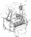
- Figs. 1A-D , 2A-B , and 3A-B show a dispenser 10 for a sheet material having a material supply monitoring and/or measurement system 100 for continuously, accurately, and precisely monitoring a remaining amount of sheet material in the dispenser 10.
- an example dispenser 10 for sheet material 12 such as tissue, paper products and/or other suitable materials, will inente a dispenser housing 14 having a cover 13, a from 16, rear 18, side 20/22, and bottom 24 sides or portions.
- the dispenser 10 further includes at least one supply 26 of sheet material, such as a roll of paper at least partially supported along the dispenser housing 14.
- the dispenser 10 includes one or more supports 28 that can engage a core or center support roll 58 of the supply so as to rotatably support the supply 26 of sheet material along, or at least partially within, the dispenser housing 14.
- the dispenser 10 further can include at least one additional supply 27 ( Figs. 1B , 1D , 2A ) of sheet material having a core or center support roll 58 that is rotatably mounted to one or more additional supports 29.
- the first supply of sheet material 26 can be a full or new roll of sheet material and the second supply 27 can be a "stub roll" that includes a roll and sheet material that has been at least partially dispensed, and can serve as a backup supply if the primary supply 26 runs out.
- a full/new roll could be loaded into supports 28 and when the full roll has been substantially dispensed, e.g., more than 50% of the supply has been dispensed, the partially dispensed roll (e.g., a "stub roll") can be moved to another position within the dispenser and can be supported by the additional supports 61 from which the "stub roll" can be fully dispensed.
- the partially dispensed roll e.g., a "stub roll”
- the supports 28 can include one or more arms 30 that are connected to the dispenser housing 14, such as at sides 20/22, and that can be biased into engagement with and/or rotatably coupled to the ends 26A/B of the supply 26 of sheet material or the core 58 thereof, so that the supply 26 of sheet material is enabled to substantially freely rotate with respect to the arms 30 as the sheet material is pulled from the supply during dispensing of the sheet material.
- the supply 26 of sheet material may be otherwise rotatably mounted to, or along, the dispenser housing 14, without departing from the present disclosure.
- the ends 26A/B of the supply 26 of sheet material may be at least partially received within grooves defined in a portion of the dispenser housing 14, e.g ., sides 20/22, or can be directly connected to at least a portion of the dispenser housing 14, such as by one or more bearings or other suitable connection mechanisms for rotatably mounting the supply 26 of sheet material.
- the additional supports 29 can include one or more arms 31 that are connected to the dispenser housing 14, such as at sides 20/22, and that can be biased into engagement with and/or rotatably coupled to the ends 27A/B of the supply 27 of sheet material or the core 58 thereof, so that the supply 27 of sheet material is enabled to substantially freely rotate with respect to the arms 31 as the sheet material is pulled from the supply during dispensing of the sheet material.
- the supply 27 of sheet material may be otherwise rotatably mounted to, or along, the dispenser housing 14, without departing from the present disclosure.
- the ends 27A/B of the supply 27 of sheet material can be directly connected to at least a portion of the dispenser housing 14, such as by one or more bearings, bushings, etc., or other suitable connection mechanisms for rotatably mounting the supply 27 of sheet material.
- the dispenser 10 further will include a feed roller 32 rotatably mounted therein.
- the feed roller 32 will be operable to rotate/pull and guide/feed the sheet material 12 along a feed or discharge path 28 towards a discharge chute 34 of the dispenser for dispensing or distribution of a length of the sheet material to a user.
- the discharge chute 34 can comprise an opening or slot 36 arranged along the bottom portion 24 of the dispenser housing 14.
- a portion of the sheet material 12 will be at least partially disposed about and in engagement or contact with the feed roller 32, such that, upon rotation of the feed roller the sheet material will be pulled, causing the supply 26 of sheet material to be rotated and an amount or length of sheet material 12 to thus be fed to and through the discharge chute 34.
- the feed roller 32 can have a diameter selected for feeding a prescribed or predetermined or known length or amount of sheet material.
- the feed roll 32 can have a diameter or size selected to feed an 20,32 cm (8"), 25,4 cm (10"), 30,48 cm (12") or other predetermined length of sheet material for each revolution or pre-set series of revolution per dispensing operation.
- the feed roller 32 is automatically driven by a drive mechanism 38 (shown in Fig. 4 ) that activates when one or more sensors detect a predetermined condition, for example, when a proximity sensor 33, such as an infrared sensor, detects the presence of a user's hand adjacent or below the dispenser housing 14, or detects the absence of sheet material extending from the discharge chute 34.
- the one or more sensors also can include a switch or lever, e.g., flapper or pawl member 70, arranged along a tear bar 47 or other cutting mechanism that is activated when a user tears away a select amount of sheet material.
- the feed roller 30 can be manually driven, e.g., when an operator actuates a knob or lever or pulls or tensions a portion of sheet material 12 extending from the discharge chute 36 (not shown).
- the drive mechanism 38 of the feed roller comprises a motor 40, such as a DC motor (e.g., brush or brushless DC motor), an AC motor, stepper motor, servo motor or other similar motor or actuator.
- the motor 40 can be powered by a battery pack 42 or other power source arranged at least partially within or along the dispenser housing 14,
- the drive mechanism 38 also can be integrated with the feed roller 32, or can be arranged separately from the feed roller 32 and can be in communication therewith and/or drive the feed roller through one or more gear assemblies 39, though other transmissions mechanisms, devices, assemblies, etc., such as one or more pulley assemblies, can be used without departing from the scope of the present disclosure. Any suitable arrangement or configuration for the drive mechanism can be employed, however, without departing from the scope of the present disclosure.
- Figs. 1 A-B , 1D and 3A further show that the dispenser 10 can include one or more guide or pressing rollers 44/46 rotatably mounted along the feed path 28 of the sheet material, adjacent the feed roller 32, in positions so as to contact and/or functionally engage and guide the sheet material 12 therebetween as the sheet material is fed along the discharge path 28 for dispensing thereof.
- the guide rollers 44/46 can be biased toward the feed roller 32, such as by one or more springs or other suitable biasing members to contact and engage the sheet material between each guide roller and the feed roller, however, one or more of the guide rollers can be fixed, i.e., unbiased, without departing from the present disclosure. Additionally, although a pair of pressing rollers 44/46 can be used as indicated in Figs.
- any number, arrangement, and/or configuration of biased or unbiased guide rollers such as one, three, or four guide rollers also can be employed without departing from the present disclosure, e.g. as indicated in Figs 2A and 3A the dispenser 10 further can include one or more cutting mechanisms as such as a blade or tear bar 47 ( Fig. 2A ), configured to cut, perforate, tear or otherwise sever the sheet material.
- a cutting mechanism can be disposed along the feed roller 32 and can be movable therewith to cut or perforate the sheet material 12 as it is dispensed.
- the cutting mechanism can include a tear bar 47, with a jagged or serrated edge, that is arranged along or adjacent the discharge chute 34 of the dispenser to allow a user to tear off a desired amount or length of sheet material 12 after it is dispensed.
- the supply/supplies 26 and 27 of sheet material will be rotatably coupled to the supports 30 and additional supports 31, respectively.
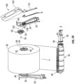
- the supports 30/31 generally include or are coupled to connecting members or to hubs 48/49 at each end of the supply or other suitable attachment mechanism operable and/or configured to be connected to the ends 26A/B or 27A/B of the supplies 26/27 of sheet material, such that the supplies 26/27 of sheet material are rotatable therewith.
- hubs 48 can include a hub body 50 that is rotatably engaged with or coupled to a corresponding support arm 30.
- each hub body 50 can have a substantially circular or disk-like shape, though any suitable shape, such as a semi-spherical or polygonal shape, can be employed without departing from the present disclosure.
- Each hub body 50 also can have a hole or opening 52 defined therethrough and configured to receive a pin 54 or other suitable mechanism that further can be received through a corresponding hole or opening 56 in an associated or adjacent arm 30 to rotatably couple each hub body 50 to its arm 30, as shown in Fig. 3A .
- the pin 54 can be secured in place by a clip or locking ring 57 or other suitable attachment mechanism ( Fig. 3A ).
- the secondary supply or stub roll 27 can be similarly rotatably supported from its support 59.
- each of the supplies 26/27 of sheet material can include a rigid supply roller or core 58 around which the sheet material 12 is rolled or otherwise disposed.
- Each supply roller 58 generally can include a cylindrical body 60 with a cavity 62 defined therein and an opening 64 at each of its ends 60A/B ( Figs. 1A , 2B , and 3A ). shaped, sized, dimensioned or otherwise configured such that at least a portion of the hub body 50 of each hub is at least partially received within a corresponding opening 64 at each end 60A/B of the supply roller body 60. For example, as shown in Figs. 1B and 2B .
- the hub body 50 can include a frustoconical, conical, or otherwise angled portion 66 that fits into an opening 60A/B and projects at least partially into the internal cavity 62 of the supply roller body 60. e.g., in frictional engagement therewith, such that the core 58 of the sheet material supply and thus the supply of sheet material are rotatable.
- Each hub body 50 further can include one or more stoppers, tabs or other suitable projecting portions 68 that are sized, dimensioned, or configured to engage at least a portion of the supply roller body 60 to prevent slippage between the hub bodies 50 and supply roller or core 58 during dispensing of the sheet material.
- the proximity sensor 33 for detecting the presence of a user's hand or other suitable portion of a user's body or object can be disposed along the dispenser housing 14.
- the sensor 33 will be positioned so as to detect the presence of a user's hand or other portion within an area or proximity below the dispenser housing 14, and will send a signal to a controller 110, in response to which operation of the dispenser can be activated to dispense a measured/select amount of sheet material.
- Fig. 2A additionally shows that the dispenser 10 can include a pivotally mounted lever, flapper or pawl member 70 generally located proximate to the tear bar 47.
- the flapper member 70 is positioned such that movement of sheet material into the tear bar 47 for severance thereof causes the sheet material to at least partially engage and pivot or otherwise move the flapper member 70 from a first position 72 to a second position 74.
- a signal means 76 can be in communication with the flapper member 70 such that movement of the flapper member 70 to its second position 74 can cause the signal means 76 to transmit or otherwise send a signal, e.g ., to notify or indicate to the controller 110 of the dispenser, that the sheet material 10 has been removed or at least pulled or otherwise engaged against the tear bar 47.
- the dispenser 10 can include a sheet material detection sensor 80 operable to detect sheet material 10 in and along the discharge chute 34.
- the sheet material detection sensor 80 can include at least one signal emitter and at least one signal detector 82/84 (e.g., at least one IR signal emitter and at least one IR detector) disposed along opposing portions of the discharge chute 34.
- the emitter and detector will be focused or directed across at least a portion of the discharge path, such that when sheet material is present in the discharge chute/path, the detector will not receive a signal from the emitter, i.e. , the signal will be blocked, indicating the presence of the sheet material in the discharge chute, while the location of the sensor 80 also substantially avoids inadvertent detection of a user's hand.
- the proximity sensor 33, the flapper or pawl member 70. and the sheet material detection sensor 80 can include any suitable components, have any suitable construction, and/or perform any suitable functions or operations, without departing from the scope of the present disclosure, for example, as detailed in U.S. Patent Application Nos. 13/155,528 and 15/173,970 .
- the dispenser 10 additionally includes a sheet material monitoring and/or monitoring system 100 generally shown in Figs. 2A-3B , and operable to substantially continuously measure the feeding of lengths of the sheet material during each operation of the dispenser for dynamically determining and tracking the amount of remaining sheet material 12 of the supplies 26/27 of sheet material with enhanced precision and accuracy as the sheet material continues to be dispensed from the dispenser.
- the monitoring system 100 includes a plurality of magnets (102, 104) disposed along the supply 26 and/or the supply 27. for example, attached along at least one end, e.g. , ends 26A or 26B, thereof, such that the plurality of magnets (102, 104) is rotatable with the supply 26 and/or 27 during a dispensing operation.
- the monitoring system 100 includes a plurality of magnets 104, e.g.. arranged about one of the ends of the supply 26 and/or the supply 27, and rotatable therewith, which plurality of magnets 104 is arranged to form a magnetic ring 106 with adjacent magnets having opposite and alternating polarities, the magnets arranged with alternating polarities, north, south, north, south and so on ( Fig. 3B ).
- the plurality of magnets 104 can include rare-earth magnets, electro magnets, and/or otherwise magnetized materials.
- the magnetic ring 1 06 of magnets 104 can be mounted to or arranged about a hub 48 or 49 of at least one of the support arms 30 or 31 and to which an end of the core of the supply 26 or 27 of sheet material is mounted so as to be rotatably supported by the support arms.
- the present disclosure is not limited to a specific configuration and/or arrangement of magnet(s), however, and the plurality of magnets can be mounted along or connected to the supply/supplies of sheet material, such as by being directly connected to or formed with the supply roller or core 58 for the supply/supplies of sheet material or otherwise connected thereto, such that the magnets rotate with the rotation of the supply of sheet material during a dispensing operation, as generally shown in Fig. 2B .
- the monitoring system 100 also will include at least one sensor 108, for example, a reed switch, a hall element, proximity sensor, or other suitable sensing mechanism or device operable to measure or detect the presence of a magnet and/or fluctuations or variations in a magnetic field.
- the at least one sensor 108 can be arranged or positioned within or along the dispenser housing typically being located substantially adjacent the plurality of magnets 104, in a position to detect the presence of the magnet(s) and/or measure or otherwise detect fluctuations or variations in the magnetic field created as the plurality of magnets is rotated or otherwise moves past the sensor with the rotation of the supply 26 of sheet material during a dispensing operation.
- the senor 108 can be arranged along an arm 30 substantially adjacent or proximal to the rotating hub 48 to which the magnet or ring of magnets is mounted, such as shown in Fig. 3A .
- the sensor 108 further can be received within a cavity or chamber 109 defined in the arm 30 and can be secured, such as by a snap fitting, fastener or other suitable connection mechanism.
- the chamber 109 may be at least partially enclosed by a cover 112 or other portion that can be removably attached to the arm 30.
- Other sensors, detecting mechanisms, etc., such as an encoder or other detector capable of monitoring and determining the rotation of the sheet material supply also can be used.
- a similar sensor 108 further can be arranged along the dispenser housing substantially proximate or adjacent to the supports 59 for the second ("stub") roll 27.
- This sensor 108 can be located and configured to function in a substantially similar manner as the sensor 108 monitoring rotation of the main or primary supply 26.
- the magnet 102 and sensor 108 for the second (stub) roll 27 do not have to be used as it is not necessary or required that the dispenser include a second or stub roll; that the monitoring system monitor the second (stub) roll or to do so in the same manner as the supply 26.
- the sheet material of the second supply roll 27 generally can be maintained out of engagement with the feed roller until the main or primary supply 26 has been substantially exhausted, or the supply is detected as having a selected minimum amount remaining sufficient to trigger feeding of sheet material from the second supply roll.
- the detection of the magnet passing by, or fluctuations, variations and/or changes in the magnetic field being detected by the sensor 108 can be correlated with an angle, an annular distance and/or a number of rotations (including partial rotations) of the supply 26 of sheet material as the sheet material is dispensed.
- the changes in polarities detected as the ring of magnets is rotated can be counted and empirically correlated to a specific number of rotations or an amount or distance of rotation of a supply 26/27 of the sheet material, e.g., during one dispensing operation, 2 rotations may be detected for feeding 10" of sheet material, while 2.1, 2.3 or 2.5 rotations may be detected during subsequent dispensing operations for feeding a 10" length of the sheet material.
- radian measurements can be used to determine a substantially precise diameter of the sheet material remaining on the supply roll based on the number of rotations of the supply roll detected/measured by the sensor 108.
- the monitoring system 100 may communicate signals indicative of the number of rotations of the supplies 26/27 of sheet material operating and being measured by the sensor 108 during a dispenser operation or cycle to a controller 110 ( Fig. 5 ) of the dispenser 10 such as by a wired or wireless connection.
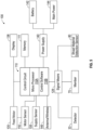
- Fig. 5 generally illustrates an example controller or control system 1 10 for the dispenser, which can comprise a processor 110A, programing or control software 110B, including programing, instructions, workflows, etc. for facilitating operation of the monitoring system.
- the controller 110 further can communicate with a signal means 128, including the hand or proximity detector 33, the pawl or flapper bar member 70, and the sheet material detection sensor 80; and in response to signals therefrom, control operation of the feed roller motor and/or provide output signals a display 136.
- a power supply 140 which can include a battery 142 or AC power connection 144 also generally will be connected to the controller for powering the operation of the dispenser. Further examples of control systems are shown in U.S. Patent Application Nos. 15/173,970 and 15/185,776 .
- the controller receives inputs from the supply roll sensor 108 as to the number of rotations thereof, and from a motor sensor or detector assembly 116 that monitors and detects rotations of the motor and/or the feed roller; and in response, the dispenser controller 110 can use this measured information to calculate a remaining diameter of the supply of the sheet material following completion of each dispensing operation or cycle, or at least selected ones of the dispensing cycles. This calculated/updated remaining diameter or amount further can be compared to an initial and/or a final diameter of the sheet material to determine a substantially precise percentage of sheet material remaining in the dispenser.
- the monitoring system 100 can provide for substantially precise, continuous, and updated monitoring of the amount of sheet material remaining in the dispenser.
- the controller further can receive inputs from the sensor 108 (or sensors) to verify that sheet material was actually dispensed from one of the supplies 26/27, For example, operators often may just dispose of (i.e., throw away) partially dispensed ("stub") rolls as opposed to moving the roils to the additional support 29 for fully dispensing the sheet material/paper therefrom, which can waste a considerable amount of sheet material. Accordingly, the sensor 108 dispensed adjacent to the support 29 can send a signal to verify that the second (“stub") roll has been loaded for dispensing, as well as the number of rotations thereof for determining an amount of sheet material remaining on this roll.
- the sensor 108 dispensed adjacent to the support 29 can send a signal to verify that the second (“stub") roll has been loaded for dispensing, as well as the number of rotations thereof for determining an amount of sheet material remaining on this roll.
- the monitoring system 100 additionally can include a means for automatically determining the length of sheet material dispensed during each distribution of sheet material by an operator.
- the length of the sheet material dispensed can be determined, based at least in part, on a programmed or known number of rotations of the motor 40 and/or the feed roller 32.
- the feed roller 32 can have a specific diameter selected for feeding a substantially fixed or known length of sheet material with each rotation thereof.
- monitoring the number of rotations of the feed roller 32 and/or its motor enables the controller to determine completion of each dispensing cycle and also can allow for a substantially more precise determination of the length of sheet material dispensed during each cycle including cycles or operations that may have been prematurely halted, such as by a user pulling/tearing the paper before the motor has fed a full sheet length.
- the number of rotations of the motor 40 or a drive shaft 41 thereof for each rotation of the feed roller 32 can be determined, for example, based on a specific pulley or gear ratio between the or a drive shaft 41 thereof for each rotation of the feed roller 32 can be determined, for example, based on a specific pulley or gear ratio between the motor 40 and the feed roller 32, and a unit length of sheet material dispensed can be determined based upon the number of rotations of the motor 40 or its drive shaft.
- the correlation of the number of rotations of the motor 40 and/or feed roller for each unit length of sheet material will be communicated to the controller 110 and be used to determine a specific length of sheet material that has been dispensed, and/or when a specified length of the sheet material (e.g ., 25,4 cm (10"), 30,48 cm (12"), etc....,) has been dispensed, and a dispensing operation completed, by monitoring the operation of the motor 40 and/or rotation of the feed roller 32.
- a specified length of the sheet material e.g ., 25,4 cm (10"), 30,48 cm (12"), etc....
- the monitoring system 100 further can include at least one sensor assembly 116 that is located/positioned to continuously monitor rotations of the motor.
- the sensor assembly 116 can be in communication with, e.g ., wired or wirelessly, and send a signal indicative of the number of motor rotations to the dispenser controller 110.
- the sensing assembly 116 can include at least one sensor 118, for example, a reed switch, a hall element, or other suitable sensing mechanism operable to measure or detect variations in magnetic field. As indicated in Fig.
- the sensor assembly 116 can be located adjacent the drive shaft 41 and further can include at least one magnet 120 arranged along the drive shaft 41 of the motor, with the sensor 118 being arranged or positioned on or adjacent the motor 40 substantially adjacent the drive shaft 41, such that the at least one sensor 118 can detect the presence of and/or fluctuations or variations in magnetic field as the at least one magnet 120 rotates or moves past the sensor 118 with the rotation of the drive shaft 41.
- a similar sensor assembly can be additionally arranged about the feed roller 32, to determine the movement, number of rotations, or rotation angle thereof. Based on the number of rotations of the motor or the feed roller, as detected-'determined by the sensor assembly, a substantially precise length of sheet material dispensed can be monitored and detected/determined.
- the dispenser controller 110 receives the information from the monitoring system 100 as to both the number of rotations of a supply of sheet material and the number of rotations of the feed roller 32, and/or its drive motor 40, detected during each dispensing cycle of operation.
- the feed roller 32 and its motor 40 can be operated for a predetermined number of rotations to feed the desired, predetermined or pre-selected length/amount of the sheet material (e.g. , 20,32 cm (8"), 25,4 cm (10"), 30,48 cm (12"), .).
- the controller 110 can then use the reported/monitored rotations of the supply of sheet material, compared with prior measurements of the supply, to determine a current or updated diameter of the supply of sheet material. This calculated, substantially dynamically updated diameter further will be compared to a base value (e.g. , the diameter of a full roll or an empty/near empty roll) to determine a remaining amount of sheet material. If this calculated remaining amount of sheet material is below a threshold amount, a notification can be provided to signal a need for a replacement change of the supply.
- a base value e.g. , the diameter of a full roll or an empty/near empty roll
- a number of motor rotations and/or rotations of the feed roller can be generally correlated or known. For example, based upon size of the feed roller and gearing of the motor with respect to the feed roller, and/or historical operation data, an amount of paper dispensed per motor rotation can be known or otherwise determined. Based upon such a known or calculated value of paper dispensed per motor rotation, and the detected or measured number of motor rotations required to complete one paper roll rotation, the diameter of the paper or sheet material supply roll can determined following a dispensing operation.
- the remaining diameter or supply of the sheet material can be dynamically calculated, e.g., after a selected number of dispensing cycles or operations, or after substantially each dispensing cycle or operation.
- This dynamically determined diameter or remaining amount of the supply of sheet material thereafter can be compared to a threshold value or a base value, such as a full or empty/near empty roll diameter, to determine a remaining amount of the supply of sheet material and/or if a low paper notification or signal should be provided such as via display or sent to maintenance personnel by the controller.
- the dispenser can be operated for a calibration cycle or start-up operation ( Fig. 6A ). For example, after a roll or supply of paper material has been loaded into the dispenser, upon closing of the cover and/or engagement of a control switch for the dispenser (Step 200), the dispenser can be operated to engage and run the feed roller for at least an initial cycle (Step 201). As indicated at Step 202, the motor and/or feed roller rotations will be monitored as will the rotations of the supply of sheet material during the dispensing cycle.
- Step 203 a number of motor and/or feed roller rotations for each rotation of the supply roll of the sheet material is calculated or determined; and based upon this calculated or determined value, the remaining diameter of the sheet material supply roll can be determined or calculated (Step 204). As indicated at Step 206, this process is repeated for a selected number of initial dispensing cycles (e.g., 5-10 cycles, although greater or fewer cycles also can be used).
- a selected number of initial dispensing cycles e.g., 5-10 cycles, although greater or fewer cycles also can be used.
- an average remaining diameter is calculated (Step 207).
- a next cycle/operation of the dispenser is then run (Step 208), and the calculated remaining diameter of the sheet material supply roll is compared to the average remaining diameter derived from the calibration cycles (Step 209). If this next remaining diameter value is greater than the average remaining diameter value developed by the calibration cycles, the system can generate an error signal (Step 211) and thereafter can alert maintenance staff to check the dispenser, and can reset and renin the calibration operation (at least for an abbreviated number of cycles) (Step 312). If the next calculated diameter of the sheet material supply is not greater than the average remaining diameter developed by the calibration cycles, the dispenser can be signaled as ready for operation (at Step 213).
- the monitoring system 100 will be operable during at least selected dispensing operations to calculate a remaining amount or diameter of the sheet material supply within the dispenser.
- the operation of the dispenser generally will start in response to the controller receiving a signal from a hand sensor or other detector 130 ( Fig. 5 ), which can indicate the presence of a user (e.g., their hand), or alternatively, the engagement and/or pulling of a hanging sheet of the sheet material can initiate a dispensing operation.
- the feed motor for the feed roller is engaged and operated to feed a selected length of the sheet material (Step 221). As the feed roller is operated to feed the selected length of sheet material, the supply of sheet material generally is rotated.
- the rotation of the supply of sheet material is monitored to detect the number of rotations thereof for feeding the selected length of material (Step 222A), while the motor and/or feed roller also are monitored (Step 222B). Based on this information, the system will determine the number of rotations of the motor per substantially complete rotation of the supply roll (Step 223). Using the determined or calculated number of motor rotations per rotation of the supply roll and number of motor/feed roller rotations detected, a remaining paper diameter of the supply roll is calculated, at Step 224.
- This calculated remaining paper diameter is then compared to a threshold value at Step 226 (and/or to values of a full and a deleted roll to calculate a remaining paper/supply percentage). If the calculated paper diameter is greater than the threshold value, the dispenser can be reset for a next dispensing operation, as indicated at Step 227. If the calculated paper diameter is less than a selected or determined threshold value, as indicated at Step 228, a signal or alert of a low paper supply can be generated and provided either via the display 136 ( Fig. 5 ) connected to the controller 110 of the dispenser, or can be otherwise transmitted or sent to maintenance staff, such as an antenna or wireless connection 146.
- the number of rotations of the feed roller preferably can be set to feed a known amount of sheet material to be dispensed for each cycle
- the rotations of the feed roller 32 and/or the motor 40 still generally can be monitored to determine the amount of sheet material fed. For example, during a manual operation, or if the operation of the dispenser is interfered with, a full length of sheet material may not be fed.
- the monitoring system can actively monitor the amount of sheet material fed per each cycle to provide a running total or substantially dynamically determined amount of remaining sheet material with as much precision or accuracy as possible during each operation of the dispenser 10.
- the controller 110 further may be in communication with a notification system operable to indicate the remaining amount of sheet material in the dispenser determined by the controller.
- the notification system can include a display, such as an LED or LCD display 136 ( Fig. 3 .), arranged along an external portion of the housing operable to numerically or graphically indicate the amount of sheet material remaining.
- the notification system can include a series of lights, such as LED lights, arranged on the housing that activate or deactivate based on the remaining amount of sheet material determined by the controller.
- the controller can be configured to communicate with a computer, server, or mobile device, e.g ., a tablet, smartphone, watch or other smart device.
- the controller 110 can include, or otherwise be in communication with, an antenna, such as a Bluetooth, RF, or WiFi antenna, such that signals indicative of the remaining amount of sheet material can be communicated to the computer, sensor, or mobile device, to facilitate continuous, remote monitoring of the remaining amount of sheet material.
- an antenna such as a Bluetooth, RF, or WiFi antenna
- the controller 110 also can include a memory 111 that can store historical data for a predetermined time period. For example, the recorded measurements of the supply of sheet material over the past hour, two hours, day, etc ..., can be stored and used by the controller (or a computer or server linked to the controller) to develop a projected end of supply based on historical uses/trends. This projected end of supply can be communicated to maintenance staff, such as wirelessly from the controller or through the display of the dispenser (e.g., displaying a remaining percentage or projected run-out of the supply), to allow them to prioritize servicing of the dispenser ( i.e., immediate attention is required or replacement may not be needed for several hours or until the next day.)
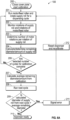
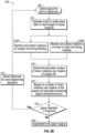
- Fig. 7 shows a flow diagram illustrating an exemplary process 300 of operation of the dispenser in various modes, e.g., in an automatic feeding mode.
- the motor 40 can start or otherwise be activated, for example, upon detection of a user's hand or an object by the proximity sensor 33, or by activation of the flapper member 70, such as due to a user pulling a hanging tail or paper length, etc.
- the controller 110 can determine whether the monitoring system 100 has detected rotation of the motor 40 (at Step 304). If motor rotation is signal is provided by the monitoring system, the controller 110 can activate the sheet material detection sensor 80, to cause the emitter of the sheet material detection sensor to emit at least one pulse (Step 306). Additional pulses can be sent after each motor rotation is detected by the measurement system.
- the operation of the sheet material detection sensor generally will be tied to the actual detected rotations of the motor ( i.e ., the motor driveshaft), with the number of pulses and timing thereof varying during each dispensing operation.
- Step 308 when a pulse is sent, a determination can be made as to whether the sheet material detection sensor 80 is obstructed or blocked by the sheet material. If the sensor 80 is not blocked or obstructed, rotation of the motor 40 can be stopped or otherwise deactivated (Step 318) because, for example, the sheet material has already been removed by a user.
- Step 310 If the sheet material detection sensor 80 is blocked or obstructed, however, a determination can be made as to whether a paper jam has been detected at Step 310. If a paper jam is detected, the motor 40 can be stopped or otherwise deactivated. If a paper jam is not detected, the controller 110 can determine whether a stop signal has been received from the flapper member 70 (at Step 312), e.g., if the flapper member 70 has been moved to its second position 74 due to engagement with the sheet material, such as for tearing or separating the sheet material.
- the motor 40 can be stopped or deactivated (at Step 318). If a stop signal has been received from the flapper member 70, the motor 40 can be stopped or deactivated (at Step 318). If a stop signal is not received from the flapper member 70, a determination can be made by the controller 110 as to whether the number of actual rotations of the motor detected by the measurement system corresponds to the number of expected motor rotations for dispensing the desired length of sheet material (at Step 314).
- sheet material is signaled as missing or tom, e.g., based upon activation of the flapper member 70 or detection of the paper being missing in the discharge chute by the sheet material sensor 80, before the motor completes the corresponding number of revolutions to feed a prescribed length of sheet material, this might be indicative of an early tear by a user and the motor can be stopped, for example, to avoid sheet material extending from the discharge chute (e.g., a tail) if not wanted or to avoid or otherwise prevent a paper jam.
- the motor can be stopped, for example, to avoid sheet material extending from the discharge chute (e.g., a tail) if not wanted or to avoid or otherwise prevent a paper jam.
- Step 314 it is determined that the motor 40 has completed the corresponding number of revolutions for feeding the prescribed length of sheet material, the motor 40 may be stopped or otherwise deactivated. However, if not, the process can return to step 304 to continue to detect further motor rotations. If no motor rotations are detected, the process 300 may continue again to Steps 310 through 314.
- Steps 302 to 316 can be arranged in any suitable sequence or can be omitted entirely, without departing from the scope of the present disclosure. Also, additional steps can be included, without departing from the scope of the present disclosure. For example, upon stoppage of the motor, the sheet material, detection sensor can be activated or pulsed to verify that the discharge chute is clear of sheet material and to reset the dispenser for subsequent operations.
- Activating, e.g., pulsing, the sheet material detection sensor to correspond to the rotations of the motor can substantially improve the efficiency of the dispenser.
- some dispensers may pulse a sheet material detection sensor continuously during running of the motor, and, as a result, often will have longer pulsing intervals with more pulses typically being generated as the motor runs slower, and thus the dispensing time becomes longer, due to a lower power condition.
- the sheet material detection sensor since the sheet material detection sensor pulses with each detected motor rotation, the sheet material detection sensor generally will be activated/pulsed the same number of times during each dispensing operation independently of motor speed (e.g., during low power conditions), preserving power.
Landscapes
- Health & Medical Sciences (AREA)
- Public Health (AREA)
- Controlling Sheets Or Webs (AREA)
Claims (14)
- Spender (10) zum Abgeben von Blattmaterial, umfassend:einen Rollenträger (28) zum Tragen eines Vorrats (26) von Blattmaterial;eine Zuführwalze (32), die entlang eines Zuführpfads (28) des Blattmaterials dem Vorrat (26) von Blattmaterial nachgeordnet angeordnet ist, wobei die Zuführwalze (32) das Blattmaterial bei der Drehung der Zuführwalze (32) ergreift und von dem Vorrat (26) von Blattmaterial abzieht, um es entlang des Zuführpfads (28) zuzuführen;eine Steuerung (110), die mit der Zuführwalze (32) in Verbindung steht und eine Programmierung zum Überwachen der Drehung der Zuführwalze (32) während eines Abgabezyklus aufweist, um eine ausgewählte Länge des Blattmaterials von dem Vorrat (26) von Blattmaterial zuzuführen;ein Materialvorrats-Überwachungssystem (100), das mit der Steuerung (110) in Verbindung steht und betreibbar ist, um eine Anzahl von Umdrehungen oder einen Drehwinkel des Vorratsblattmaterials während mindestens einer Reihe von Abgabezyklen zu erfassen, wobei das Materialvorrats-Überwachungssystem (100), eine Mehrzahl von Magneten (102, 104) aufweist, die mit dem Vorrat (26, 27) von Blattmaterial drehbar ist, und mindestens einen Sensor (108), der betreibbar ist, um Schwankungen oder Variationen eines Magnetfelds zu messen oder zu erfassen, wenn die Mehrzahl von Magneten (102, 104) gedreht wird oder sich mit der Drehung des Vorrats (26) von Blattmaterial auf andere Weise an dem mindestens einen Sensor (108) vorbeibewegt, wobei nach mindestens jedem aus der Reihe von Abgabezyklen basierend auf den Schwankungen oder Variationen des Magnetfelds ein verbleibender Durchmesser des Vorrats (26) von Blattmaterial im Wesentlichen dynamisch bestimmt wird; undeinen Antriebsmotor (40), der mit der Zuführwalze (32) gekoppelt ist und mit der Steuerung (110) in Verbindung steht, die den Betrieb des Antriebsmotors (40) steuert, um die Drehung der Zuführwalze (32) zum Zuführen der ausgewählten Länge des Blattmaterials anzutreiben;wobei die Mehrzahl von Magneten (104) so angeordnet ist, dass sie einen Magnetring (106) bildet, wobei benachbarte Magnete aus der Mehrzahl von Magneten (104) entgegengesetzte und alternierende Polaritäten aufweisen.
- Spender (10) nach Anspruch 1, wobei der Rollenträger wenigstens einen Tragarm (30, 31) aufweist, wobei der Magnetring (106) von Magneten (10) an einer Nabe (48, 49) des wenigstens einen Tragarms (30, 31) um diese herum angebracht oder angeordnet ist, an dem ein Ende (26A, 26B) des Kernabschnitts (58) des Vorrats (26, 27) von Blattmaterial so angebracht ist, dass es durch den Tragarm (30, 31) drehbar getragen wird.
- Spender (10) nach Anspruch 1 oder 2, der ferner mindestens eine Druckwalze (44, 46) aufweist, die entlang des Zuführpfads (28) angeordnet und mit der Zuführwalze (32) drehbar ist, sodass das Blattmaterial bei Drehung der Zuführwalze (32) zwischen der mindestens einen Druckwalze (44, 46) ergriffen und gezogen wird.
- Spender (10) nach Anspruch 1 oder 2, der ferner ein Paar beabstandeter Druckwalzen (44, 46) umfasst, die an die Zuführwalze (32) angrenzen und mit dieser in angetriebenem Kontakt stehen, um sich mit der Drehung der Zuführwalze (32) zu drehen, und wobei das Blattmaterial zwischen den Druckwalzen (44, 46) und der Zuführwalze (32) bei deren Drehung ergriffen und gezogen wird.
- Spender (10) nach einem der vorhergehenden Ansprüche, wobei der mindestens eine Sensor (108) einen Schalter, ein Hall-Element oder einen Näherungssensor umfasst, der angrenzend zu dem Kernabschnitt (58) des Vorrats (26) von Blattmaterial in einer Position angeordnet ist, um Schwankungen oder Änderungen des Magnetfelds zu erfassen, die erzeugt werden, wenn die Magnete (102, 104) den mindestens einen Sensor (108) passieren, wenn der Kernabschnitt (58) des Vorrats (26) von Blattmaterial gedreht wird.
- Spender (10) nach einem der vorhergehenden Ansprüche, der ferner einen oder mehrere Sensoren (33) umfasst, die betreibbar sind, um das Vorhandensein eines Gegenstands zu erfassen, und bei Erfassung des Gegenstands den Antriebsmotor (40) zum Zuführen der ausgewählten Länge des Blattmaterials zu aktivieren.
- Spender (10) nach einem der vorhergehenden Ansprüche, der ferner einen Blattmaterial-Erfassungssensor (80) umfasst, der entlang des Zuführpfads (28) angeordnet und dazu eingerichtet ist, das Entfernen ausgewählter Längen von Blattmaterial zu erfassen.
- Spender (10) nach Anspruch 7, wobei der Blattmaterial-Erfassungssensor (80) bei einer erfassten Drehung des Vorratsblattmaterials (26) aktiviert wird.
- Spender (10) nach einem der vorhergehenden Ansprüche, der ferner eine Mehrzahl von Vorräten (26, 27) von Blattmaterial umfasst, wobei das Materialvorrats-Überwachungssystem (100) so betreibbar ist, dass es Umdrehungen oder einen Drehwinkel von jedem aus der Mehrzahl von Vorräten (26, 27) von Blattmaterial erfasst.
- Spender (10) nach Anspruch 9, wobei das Materialvorrats-Überwachungssystem (100) so betreibbar ist, dass es verifiziert, dass einer oder mehrere aus der Vielzahl von Vorräten von Blattmaterial (26, 27) in den Spender (10) geladen wurden.
- Verfahren zum Betreiben eines Spenders (10) nach Anspruch 1, wobei das Blattmaterial Papier ist, wobei das Verfahren Folgendes umfasst:Drehen der Zuführwalze (32), um eine Papierlänge von der Vorratsrolle (26) zuzuführen;Erfassen einer Anzahl von Umdrehungen der Vorratsrolle (26) zum Zuführen der Papierlänge unter Verwendung des Materialvorrats-Überwachungssystems (100), das mit der Steuerung (110) in Verbindung steht;Bestimmen einer Anzahl von Umdrehungen des Motors (40), der die Drehung der Zuführwalze (32) antreibt, pro Umdrehung der Vorratsrolle (26) während des Zuführens der Papierlänge; undBestimmen eines Durchmessers des verbleibenden Papiers der Vorratsrolle (26) basierend auf der Anzahl von Umdrehungen des Motors (40) pro Umdrehung der Vorratsrolle (26) und einer pro Umdrehung des Motors (40) ausgegebenen Papiermenge.
- Verfahren nach Anspruch 11, wobei das Drehen der Zuführwalze (32) das Betreiben des Motors (40) umfasst, um die Zuführwalze (32) für eine Anzahl von Umdrehungen anzutreiben, die ausreicht, um eine ausgewählte Papierlänge zuzuführen, oder bis ein Stoppsignal von einer Steuerung (110) des Spenders empfangen wird.
- Verfahren nach Anspruch 11 oder 12, das ferner das Vergleichen des Durchmessers des verbleibenden Papiers mit einem Schwellenwert und das Anweisen eines Zustands mit wenig verbleibendem Papier umfasst, wenn der Schwellenwert den Durchmesser des verbleibenden Papiers überschreitet.
- Verfahren nach Anspruch 11, 12 oder 13, das ferner das Aktivieren des Motors zum Antreiben der Zuführwalze (32) zum Zuführen der Papierlänge bei Erfassung eines Gegenstands mit einem oder mehreren Sensoren (33) umfasst.
Applications Claiming Priority (2)
| Application Number | Priority Date | Filing Date | Title |
|---|---|---|---|
| US201762472866P | 2017-03-17 | 2017-03-17 | |
| PCT/US2018/022568 WO2018170219A1 (en) | 2017-03-17 | 2018-03-15 | Monitoring system for dispenser |
Publications (3)
| Publication Number | Publication Date |
|---|---|
| EP3579732A1 EP3579732A1 (de) | 2019-12-18 |
| EP3579732A4 EP3579732A4 (de) | 2020-12-23 |
| EP3579732B1 true EP3579732B1 (de) | 2025-02-12 |
Family
ID=63520776
Family Applications (1)
| Application Number | Title | Priority Date | Filing Date |
|---|---|---|---|
| EP18766752.2A Active EP3579732B1 (de) | 2017-03-17 | 2018-03-15 | Überwachungssystem für spender |
Country Status (4)
| Country | Link |
|---|---|
| US (2) | US10660486B2 (de) |
| EP (1) | EP3579732B1 (de) |
| CA (1) | CA3056233C (de) |
| WO (1) | WO2018170219A1 (de) |
Families Citing this family (29)
| Publication number | Priority date | Publication date | Assignee | Title |
|---|---|---|---|---|
| US10835086B2 (en) | 2018-04-09 | 2020-11-17 | Charles A. Osborne, JR. | Sheet material transfer system/assembly for a dispenser |
| USD854347S1 (en) | 2018-05-16 | 2019-07-23 | Bradley Fixtures Corporation | Roller for a roll towel dispenser |
| WO2019222372A2 (en) | 2018-05-16 | 2019-11-21 | Bradley Fixtures Corporation | Roll towel dispenser |
| US12268341B2 (en) | 2018-05-24 | 2025-04-08 | Charles Agnew Osborne, Jr. | Sheet material dispensing assembly with integrated gear clutch |
| WO2019226668A1 (en) | 2018-05-24 | 2019-11-28 | Osborne Charles Agnew Jr | Dispenser for rolled sheet materials |
| US11154166B2 (en) | 2018-05-24 | 2021-10-26 | Charles Agnew Osborne, Jr. | Dispenser for rolled sheet materials |
| US10638891B2 (en) * | 2018-07-20 | 2020-05-05 | Dish Network L.L.C. | Configurable paper roll dispenser sensor device |
| WO2020112540A1 (en) | 2018-11-28 | 2020-06-04 | Osborne Charles Agnew Jr | A sheet material dispenser assembly for selectively dispensing sheet material from a plurality of supplies of rolled sheet material |
| EP3893708B1 (de) | 2018-12-12 | 2024-11-20 | Charles Agnew Osborne, Jr. | Abgabeanordnung zur wahlweisen ausgabe einer vielzahl von vorräten an gewalztem blattmaterial |
| US11051663B1 (en) | 2018-12-20 | 2021-07-06 | Christopher J. Danis | Dispensing assembly for paper products |
| US11771271B1 (en) | 2018-12-20 | 2023-10-03 | Christopher J. Danis | Dispensing assembly for paper products |
| US10806307B2 (en) * | 2018-12-20 | 2020-10-20 | Christopher J. Danis | Dispensing assembly for paper products |
| KR102697112B1 (ko) | 2018-12-31 | 2024-08-22 | 킴벌리-클라크 월드와이드, 인크. | 분배기 수동 공급 감지 시스템 |
| CA3124998C (en) | 2019-01-02 | 2024-11-19 | Jr. Osborne Charles Agnew | ENERGY MANAGEMENT SYSTEM FOR DISTRIBUTORS |
| GB2581534B (en) * | 2019-02-25 | 2021-10-13 | Achton As | A sheet dispenser comprising a housing and a mount for mounting a roll of sheet material |
| US11071416B2 (en) * | 2019-03-25 | 2021-07-27 | Hunter James Hollister | Product monitoring device |
| US11132859B2 (en) * | 2019-04-09 | 2021-09-28 | Cummins-Allison Corp. | Banknote processing device and methods |
| EP3982803A4 (de) | 2019-06-14 | 2023-06-07 | Charles Agnew Osborne, Jr. | Lade- und transportsystem/-anordnung für blattmaterialspender |
| PL3771390T3 (pl) * | 2019-08-02 | 2022-02-07 | Cws International Gmbh | Sposób i układ do wykrywania poziomu napełnienia w dozowniku ręcznika higienicznego |
| US11617478B2 (en) | 2019-10-09 | 2023-04-04 | Gpcp Ip Holdings Llc | Systems and methods for product level tracking of sheet product rolls |
| WO2021154286A1 (en) * | 2020-01-31 | 2021-08-05 | Kimberly-Clark Worldwide, Inc. | Paper product dispenser with improved dispensing |
| MX2023009498A (es) | 2021-03-10 | 2023-08-23 | Kimberly Clark Co | Conjunto de husillo accionado por motor para un dispensador. |
| US12171378B2 (en) * | 2021-11-19 | 2024-12-24 | 7-Eleven, Inc. | Systems and methods for monitoring toilet paper rolls |
| US12502041B2 (en) * | 2021-12-23 | 2025-12-23 | Kohler Co. | Bathroom modular device, bathroom managing system, and bathroom managing method |
| US12329327B2 (en) | 2022-02-08 | 2025-06-17 | Vsi Health And Hygiene Group, Llc | Sheet material dispenser assembly for selectively dispensing sheet material from a plurality of supplies of rolled sheet material |
| US11812897B1 (en) | 2022-02-20 | 2023-11-14 | Christopher J. Danis | Dispensing assembly for paper products |
| CN114834944B (zh) * | 2022-03-26 | 2024-02-20 | 慈溪市正和包装有限公司 | 一种瓦楞纸加工记米方法、系统、存储介质及智能终端 |
| CN115180443A (zh) * | 2022-08-04 | 2022-10-14 | 查理·安格纽欧斯本二世 | 一种卷纸机及纸卷剩余量计算方法 |
| USD1118201S1 (en) | 2022-09-30 | 2026-03-17 | Vsi Health And Hygiene Group, Llc | Dispenser |
Citations (1)
| Publication number | Priority date | Publication date | Assignee | Title |
|---|---|---|---|---|
| EP0903311B1 (de) * | 1997-09-19 | 2003-01-08 | Kabushiki Kaisha Yuyama Seisakusho | Vorrichtung zur Spannungsregelung einer Bahn |
Family Cites Families (95)
| Publication number | Priority date | Publication date | Assignee | Title |
|---|---|---|---|---|
| US3317150A (en) | 1965-06-14 | 1967-05-02 | Mirra Cote Company Inc | Self-powered dispenser |
| US3893636A (en) | 1972-02-08 | 1975-07-08 | Garlock Inc | Tape wrapping method, apparatus, and article |
| US3892368A (en) | 1974-03-01 | 1975-07-01 | Charles Robert Ricards | Tissue dispenser |
| US4003525A (en) | 1975-07-14 | 1977-01-18 | Minnesota Mining And Manufacturing Company | Strip material unwinding device |
| US4071200A (en) | 1976-06-25 | 1978-01-31 | Stone Barry N | Electric toilet tissue dispenser |
| MX9603625A (es) | 1994-03-04 | 1997-04-30 | Kimberly Clark Tissue Co | Surtidor de rollo de papel continuo enrollado y aparato cortador. |
| US5691919A (en) * | 1995-02-28 | 1997-11-25 | Kimberly-Clark Worldwide, Inc. | System and method for collecting data on tissue consumption |
| US5672206A (en) | 1995-10-11 | 1997-09-30 | Gorman; Tom | Moistening dispenser for a roll of paper sheets |
| FR2743057B1 (fr) | 1996-01-03 | 1998-02-13 | Granger Maurice | Appareil distributeur de materiaux d'essuyage pouvant etre distribues sous forme pliee ou non pliee |
| CH692245A5 (fr) | 1998-01-20 | 2002-04-15 | Bobst Sa | Dispositif et module d'alimentation pour matériau en bande. |
| US6314850B1 (en) | 1998-01-22 | 2001-11-13 | Perrin Manufacturing Company | Paper toweling dispensing system |
| FR2787986B1 (fr) | 1998-12-31 | 2001-03-02 | Maurice Granger | Dispositif de commande de sortie de lame de coupe d'un tambour dans un appareil distributeur de materiau d'essuyage |
| US6354533B1 (en) | 1999-08-25 | 2002-03-12 | Georgia-Pacific Corporation | Web transfer mechanism for flexible sheet dispenser |
| US6408727B1 (en) | 2000-01-12 | 2002-06-25 | International Business Machines Corporation | Paper cutter using a blade lifting mechanism |
| IT1316672B1 (it) | 2000-02-28 | 2003-04-24 | Sms Demag S P A | Dispositivo di avvolgimento e svolgimento di nastri con centraggioautomatico |
| US6491251B1 (en) | 2000-03-09 | 2002-12-10 | Bay West Paper Corporation | Double core tissue roll, dispenser and method |
| US6908059B2 (en) | 2000-11-16 | 2005-06-21 | Fort James Corporation | Low reserve indicator for a paper towel dispenser |
| US6517025B1 (en) | 2000-11-16 | 2003-02-11 | Georgia-Pacific Corporation | Low reserve indicator for a coreless paper towel dispenser |
| US7648098B2 (en) | 2000-11-16 | 2010-01-19 | Georgia-Pacific Consumer Products Lp | Low reserve indicator for a paper towel dispenser |
| US6766977B2 (en) | 2001-02-27 | 2004-07-27 | Georgia-Pacific Corporation | Sheet material dispenser with perforation sensor and method |
| US6895296B2 (en) | 2001-10-19 | 2005-05-17 | Kimberly-Clark Worldwide, Inc. | Spindle system, apparatus, and methods for applying spindle apparatus |
| US6691945B2 (en) | 2001-12-28 | 2004-02-17 | Rjs Corporation | Spool drive for tension control device |
| US9010602B2 (en) | 2002-02-15 | 2015-04-21 | Georgia-Pacific Consumer Products Lp | Towel dispenser |
| US7341170B2 (en) | 2002-03-07 | 2008-03-11 | Georgia-Pacific Consumer Operations Llc | Apparatus and methods usable in connection with dispensing flexible sheet material from a roll |
| US6977588B2 (en) | 2002-06-03 | 2005-12-20 | Alwin Manufacturing Co. | Automatic dispenser apparatus |
| CA2390411A1 (en) | 2002-06-03 | 2003-12-03 | Alwin Manufacturing Company, Incorporated | Automatic dispenser apparatus |
| US7040566B1 (en) * | 2003-04-08 | 2006-05-09 | Alwin Manufacturing Co., Inc. | Dispenser with material-recognition apparatus and material-recognition method |
| FR2859367B1 (fr) | 2003-09-05 | 2006-08-11 | Maurice Granger | Dispositif de commande de sortie de lame de coupe d'un tambour dans un appareil distributeur de materiau d'essuyage |
| US7726599B2 (en) | 2003-12-31 | 2010-06-01 | Kimberly-Clark Worldwide, Inc. | Apparatus and method for dispensing sheet material |
| US7783380B2 (en) | 2003-12-31 | 2010-08-24 | Kimberly-Clark Worldwide, Inc. | System and method for measuring, monitoring and controlling washroom dispensers and products |
| US7774096B2 (en) | 2003-12-31 | 2010-08-10 | Kimberly-Clark Worldwide, Inc. | Apparatus for dispensing and identifying product in washrooms |
| US7213782B2 (en) | 2004-01-30 | 2007-05-08 | Charles Agnew Osborne | Intelligent dispensing system |
| US20060037449A1 (en) | 2004-08-17 | 2006-02-23 | L & P Paper, Inc. | Paper cutting apparatus and method of producing same |
| US7296765B2 (en) | 2004-11-29 | 2007-11-20 | Alwin Manufacturing Co., Inc. | Automatic dispensers |
| US7590467B2 (en) | 2005-01-24 | 2009-09-15 | Kimberly-Clark Worldwide, Inc. | Spindle system, apparatus, and methods for applying spindle apparatus |
| US8082827B2 (en) | 2005-10-07 | 2011-12-27 | Dispensing Dynamics International Ltd. | Hybrid towel dispenser |
| US20070176041A1 (en) | 2005-10-07 | 2007-08-02 | Global Plastics | Automated toilet paper dispenser |
| WO2007068270A1 (en) | 2005-12-14 | 2007-06-21 | Sca Hygiene Products Ab | Quantity sensing device in an automated dispenser, a dispenser containing same, a method of determining quantity and a supply roll for use in said dispenser and method |
| CA2642846C (en) * | 2006-02-18 | 2014-01-28 | Georgia-Pacific Consumer Products Lp | Electronic dispenser for dispensing sheet products |
| AU2006345764B2 (en) | 2006-07-07 | 2012-11-22 | Essity Hygiene And Health Aktiebolag | Dispenser for rolls |
| US7967235B2 (en) | 2006-10-03 | 2011-06-28 | Sca Tissue North America Llc | Dispenser that automatically transfers rolls of absorbent material, method of reloading same, and rolls of absorbent material for use in same |
| US7946522B2 (en) | 2006-10-30 | 2011-05-24 | Kimberly-Clark Worldwide, Inc. | System and method for dissipating static electricity in an electronic sheet material dispenser |
| US7735770B2 (en) * | 2007-08-31 | 2010-06-15 | Kimberly-Clark Worldwide, Inc. | Electric dispenser for dispensing sheets from a roll of perforated web material |
| US7987756B2 (en) | 2007-12-03 | 2011-08-02 | Kimberly-Clark Worldwide Inc. | Electro-manual dispenser |
| JP5106080B2 (ja) | 2007-12-14 | 2012-12-26 | 富士通コンポーネント株式会社 | ロータリカッタ装置及び該ロータリカッタ装置を備えたプリンタ装置 |
| US8833691B1 (en) | 2007-12-21 | 2014-09-16 | Georgia-Pacific Consumer Products Lp | Product, dispenser and method of dispensing product |
| US8651003B1 (en) | 2008-02-19 | 2014-02-18 | Bernard M. Vercellone | Power-operated toilet paper dispensing device and associated method |
| JP5158354B2 (ja) | 2008-03-10 | 2013-03-06 | セイコーエプソン株式会社 | ロール状被記録材の搬送装置及び記録装置 |
| US20090256022A1 (en) | 2008-04-15 | 2009-10-15 | Maurer Scott D | Sheet roll dispenser |
| US20110068129A1 (en) | 2008-04-15 | 2011-03-24 | Maurer Scott D | Sheet roll dispenser |
| US20100243696A1 (en) | 2008-06-18 | 2010-09-30 | Matthew Friesen | Electronic roll towel dispenser |
| US8600547B2 (en) | 2008-08-22 | 2013-12-03 | Georgia-Pacific Consumer Products Lp | Sheet product dispenser and method of operation |
| US7996108B2 (en) | 2008-08-22 | 2011-08-09 | Georgia-Pacific Consumer Products Lp | Sheet product dispenser and method of operation |
| US20100102101A1 (en) * | 2008-10-28 | 2010-04-29 | Perrin Manufacturing Company | Paper toweling dispenser apparatus |
| US8555761B2 (en) | 2008-10-28 | 2013-10-15 | Dispensing Dynamics International | Paper sheet material dispenser apparatus |
| WO2010083380A1 (en) | 2009-01-15 | 2010-07-22 | Dispensing Dynamics International | Paper roll dispenser with sensor attached to manual actuator |
| US8616489B2 (en) * | 2009-05-08 | 2013-12-31 | Georgia-Pacific Consumer Products Lp | Sheet product dispenser |
| US8382026B2 (en) | 2009-05-27 | 2013-02-26 | Dispensing Dynamics International | Multi-function paper toweling dispenser |
| US20110133019A1 (en) | 2009-05-27 | 2011-06-09 | Dispensing Dynamics International | Multi-function paper toweling dispenser |
| US9248988B2 (en) * | 2009-05-27 | 2016-02-02 | Dispensing Dynamics International | Multi-function dispenser for dispensing paper sheet material |
| US8807475B2 (en) * | 2009-11-16 | 2014-08-19 | Alwin Manufacturing Co., Inc. | Dispenser with low-material sensing system |
| JP5543190B2 (ja) * | 2009-12-17 | 2014-07-09 | 株式会社日本自動車部品総合研究所 | 回転検出装置 |
| US20110233318A1 (en) | 2010-03-24 | 2011-09-29 | M.I.C Industries, Inc. | Vertical sheet metal decoiling system |
| EP2587975B1 (de) * | 2010-07-02 | 2016-01-13 | Sca Hygiene Products AB | Spender und rolle mit flexiblem blattmaterial |
| US9087414B2 (en) | 2010-09-10 | 2015-07-21 | Nanoptix Inc. | Paper roll holder and ticket bezel for a ticket printer |
| WO2012075504A1 (en) | 2010-12-03 | 2012-06-07 | Oasis Brands, Inc. | Carriage assembly for sequential paper products dispensers |
| US8919233B2 (en) | 2010-12-30 | 2014-12-30 | Kimberly-Clark Worldwide, Inc. | Electronic pre-cut sheet dispenser with dispensing adjustments |
| US8800415B2 (en) | 2011-04-06 | 2014-08-12 | Solaris Paper, Inc. | Transfer mechanism for sheet material dispenser |
| CN103547523B (zh) * | 2011-05-18 | 2016-10-26 | 魁北克水电公司 | 铁磁金属带输送设备和方法 |
| US10610064B2 (en) | 2011-06-08 | 2020-04-07 | Valve Solutions, Inc. | Electronic dispenser for flexible rolled sheet material |
| US9867509B2 (en) | 2011-10-14 | 2018-01-16 | San Jamar, Inc. | Dispenser with capacitive-based proximity sensor |
| EP2700344B1 (de) | 2012-08-22 | 2015-04-15 | Achton A/S | Papierspender mit einer Einweg-Federkupplung |
| CN104869880B (zh) | 2012-12-20 | 2018-04-20 | Sca卫生用品公司 | 分配器 |
| US9756992B2 (en) | 2013-03-15 | 2017-09-12 | Vsi Import Solutions, Llc | Electronic residential tissue dispenser |
| US9604811B2 (en) | 2013-10-01 | 2017-03-28 | Georgia-Pacific Consumer Products Lp | Automatic paper product dispenser with data collection and method |
| US9918597B2 (en) | 2014-01-22 | 2018-03-20 | Sca Hygiene Products Ab | Hygienic sheet material dispenser |
| US9907441B2 (en) | 2014-04-18 | 2018-03-06 | Vsi Import Solutions, Llc | Electronic residential tissue dispenser |
| GB2546938B (en) | 2014-10-31 | 2022-03-09 | Kimberly Clark Co | Disposable product quantification and management |
| EP3640171B1 (de) | 2015-01-30 | 2023-11-22 | Kimberly-Clark Worldwide, Inc. | Verfahren zur bestimmung der nutzung und authentifizierung eines papierprodukts in einem spender |
| KR102296460B1 (ko) | 2015-02-25 | 2021-09-02 | 킴벌리-클라크 월드와이드, 인크. | 분배기 내 종이 제품의 인증을 위한 방법 및 시스템 |
| EP3261966B1 (de) | 2015-02-25 | 2019-11-20 | Kimberly-Clark Worldwide, Inc. | Verfahren und system zur bestimmung der verwendung eines gewalzten oder gestapelten produkts |
| BR112017018568B1 (pt) | 2015-03-30 | 2023-03-21 | Kimberly-Clark Worldwide, Inc | Método para a manutenção de uma pluralidade de instalações sanitárias por funcionários da manutenção |
| US12150599B2 (en) | 2015-06-04 | 2024-11-26 | Kimberly-Clark Worldwide, Inc. | Dispenser for rolled sheet materials with motorized spindle |
| US10441117B2 (en) | 2015-06-04 | 2019-10-15 | Valve Solutions, Inc. | Electronic dispenser for flexible rolled sheet material |
| US11344165B2 (en) | 2015-06-04 | 2022-05-31 | Kimberly-Clark Worldwide, Inc. | Dispenser for rolled sheet materials with cutting system |
| US10342395B2 (en) | 2015-08-28 | 2019-07-09 | Gpcp Ip Holdings Llc | Sheet product dispenser with product level gauge system |
| EP3367863B1 (de) | 2015-10-30 | 2020-12-02 | Kimberly-Clark Worldwide, Inc. | Akustisches bestimmungssystem für produktverwendung |
| NZ743701A (en) | 2016-01-06 | 2019-11-29 | Essity Operations Wausau LLC | A rolled media dispenser |
| US9920510B2 (en) * | 2016-03-03 | 2018-03-20 | David R. Hall | Smart flush toilet system |
| US11412900B2 (en) * | 2016-04-11 | 2022-08-16 | Gpcp Ip Holdings Llc | Sheet product dispenser with motor operation sensing |
| US11395566B2 (en) * | 2016-04-11 | 2022-07-26 | Gpcp Ip Holdings Llc | Sheet product dispenser |
| KR102013650B1 (ko) | 2016-04-29 | 2019-08-26 | 킴벌리-클라크 월드와이드, 인크. | 분배 시스템 |
| CN109155017B (zh) | 2016-06-28 | 2020-11-06 | 金伯利-克拉克环球有限公司 | 用于向服务人员提示关于服务区域分配器再装填需求的系统和方法 |
| US10762451B2 (en) | 2016-06-28 | 2020-09-01 | Kimberly-Clark Worldwide, Inc. | System and method for managing product usage from dispensers |
| BR112019002728B1 (pt) | 2016-08-30 | 2022-07-19 | Kimberly-Clark Worldwide, Inc | Dispenser, e, método de determinar um tipo de um produto em rolo |
-
2018
- 2018-03-15 EP EP18766752.2A patent/EP3579732B1/de active Active
- 2018-03-15 US US15/922,157 patent/US10660486B2/en active Active
- 2018-03-15 WO PCT/US2018/022568 patent/WO2018170219A1/en not_active Ceased
- 2018-03-15 CA CA3056233A patent/CA3056233C/en active Active
-
2020
- 2020-04-06 US US16/840,929 patent/US20200229659A1/en not_active Abandoned
Patent Citations (1)
| Publication number | Priority date | Publication date | Assignee | Title |
|---|---|---|---|---|
| EP0903311B1 (de) * | 1997-09-19 | 2003-01-08 | Kabushiki Kaisha Yuyama Seisakusho | Vorrichtung zur Spannungsregelung einer Bahn |
Also Published As
| Publication number | Publication date |
|---|---|
| US20200229659A1 (en) | 2020-07-23 |
| CA3056233A1 (en) | 2018-09-20 |
| WO2018170219A1 (en) | 2018-09-20 |
| US10660486B2 (en) | 2020-05-26 |
| EP3579732A4 (de) | 2020-12-23 |
| US20180263435A1 (en) | 2018-09-20 |
| CA3056233C (en) | 2021-11-09 |
| EP3579732A1 (de) | 2019-12-18 |
Similar Documents
| Publication | Publication Date | Title |
|---|---|---|
| EP3579732B1 (de) | Überwachungssystem für spender | |
| EP1455624B1 (de) | Elektrischer spender für aufgerolltes produkt | |
| US8616489B2 (en) | Sheet product dispenser | |
| US6892620B2 (en) | Electro-mechanical roll product dispenser | |
| EP2699503B1 (de) | Verfahren zur überwachung und steuerung von linearen materialdurchhang | |
| US9144352B2 (en) | Controlled dispensing sheet product dispenser | |
| US10506901B2 (en) | Sheet product dispenser with product level indicator calibration | |
| EP3886667B1 (de) | Bogenmaterialausgabeanordnung zur selektiven ausgabe von bogenmaterial aus einer vielzahl von vorräten an aufgerolltem bogenmaterial | |
| CA2638211C (en) | Electric dispenser for dispensing sheets from a roll of perforated web material | |
| US7726599B2 (en) | Apparatus and method for dispensing sheet material | |
| AU2007362884B2 (en) | Hands-free paper towel dispenser | |
| AU2012290628B2 (en) | Methods for resetting stalled pumps in electronically controlled dispensing systems | |
| US20110114782A1 (en) | Dispenser with Low-Material Sensing System | |
| AU2019472196B2 (en) | Electronic towel dispenser with low power mode | |
| JP2019001617A (ja) | テンション装置 | |
| KR101659930B1 (ko) | 슬릿이 형성된 보빈을 이용한 미싱의 밑실소요량 확인 및 표시 장치 및 방법 | |
| US20250000311A1 (en) | Dispenser assembly for selectively dispensing sheet material |
Legal Events
| Date | Code | Title | Description |
|---|---|---|---|
| STAA | Information on the status of an ep patent application or granted ep patent |
Free format text: STATUS: THE INTERNATIONAL PUBLICATION HAS BEEN MADE |
|
| PUAI | Public reference made under article 153(3) epc to a published international application that has entered the european phase |
Free format text: ORIGINAL CODE: 0009012 |
|
| STAA | Information on the status of an ep patent application or granted ep patent |
Free format text: STATUS: REQUEST FOR EXAMINATION WAS MADE |
|
| 17P | Request for examination filed |
Effective date: 20190913 |
|
| AK | Designated contracting states |
Kind code of ref document: A1 Designated state(s): AL AT BE BG CH CY CZ DE DK EE ES FI FR GB GR HR HU IE IS IT LI LT LU LV MC MK MT NL NO PL PT RO RS SE SI SK SM TR |
|
| AX | Request for extension of the european patent |
Extension state: BA ME |
|
| DAV | Request for validation of the european patent (deleted) | ||
| DAX | Request for extension of the european patent (deleted) | ||
| REG | Reference to a national code |
Ref country code: DE Ref legal event code: R079 Free format text: PREVIOUS MAIN CLASS: A47K0010320000 Ipc: A47K0010360000 |
|
| A4 | Supplementary search report drawn up and despatched |
Effective date: 20201120 |
|
| RIC1 | Information provided on ipc code assigned before grant |
Ipc: A47K 10/36 20060101AFI20201116BHEP |
|
| STAA | Information on the status of an ep patent application or granted ep patent |
Free format text: STATUS: EXAMINATION IS IN PROGRESS |
|
| 17Q | First examination report despatched |
Effective date: 20230224 |
|
| RAP1 | Party data changed (applicant data changed or rights of an application transferred) |
Owner name: VALVE SOLUTIONS, INC. |
|
| RIN1 | Information on inventor provided before grant (corrected) |
Inventor name: OSBORNE, CHARLES AGNEW, JR. |
|
| RAP1 | Party data changed (applicant data changed or rights of an application transferred) |
Owner name: KIMBERLY-CLARK WORLDWIDE, INC. |
|
| RAP3 | Party data changed (applicant data changed or rights of an application transferred) |
Owner name: KIMBERLY-CLARK WORLDWIDE, INC. |
|
| P02 | Opt-out of the competence of the unified patent court (upc) changed |
Effective date: 20240129 |
|
| GRAP | Despatch of communication of intention to grant a patent |
Free format text: ORIGINAL CODE: EPIDOSNIGR1 |
|
| STAA | Information on the status of an ep patent application or granted ep patent |
Free format text: STATUS: GRANT OF PATENT IS INTENDED |
|
| INTG | Intention to grant announced |
Effective date: 20240415 |
|
| GRAJ | Information related to disapproval of communication of intention to grant by the applicant or resumption of examination proceedings by the epo deleted |
Free format text: ORIGINAL CODE: EPIDOSDIGR1 |
|
| STAA | Information on the status of an ep patent application or granted ep patent |
Free format text: STATUS: EXAMINATION IS IN PROGRESS |
|
| GRAP | Despatch of communication of intention to grant a patent |
Free format text: ORIGINAL CODE: EPIDOSNIGR1 |
|
| STAA | Information on the status of an ep patent application or granted ep patent |
Free format text: STATUS: GRANT OF PATENT IS INTENDED |
|
| INTC | Intention to grant announced (deleted) | ||
| INTG | Intention to grant announced |
Effective date: 20240906 |
|
| GRAS | Grant fee paid |
Free format text: ORIGINAL CODE: EPIDOSNIGR3 |
|
| GRAA | (expected) grant |
Free format text: ORIGINAL CODE: 0009210 |
|
| STAA | Information on the status of an ep patent application or granted ep patent |
Free format text: STATUS: THE PATENT HAS BEEN GRANTED |
|
| AK | Designated contracting states |
Kind code of ref document: B1 Designated state(s): AL AT BE BG CH CY CZ DE DK EE ES FI FR GB GR HR HU IE IS IT LI LT LU LV MC MK MT NL NO PL PT RO RS SE SI SK SM TR |
|
| REG | Reference to a national code |
Ref country code: GB Ref legal event code: FG4D |
|
| REG | Reference to a national code |
Ref country code: CH Ref legal event code: EP |
|
| REG | Reference to a national code |
Ref country code: DE Ref legal event code: R096 Ref document number: 602018079086 Country of ref document: DE |
|
| REG | Reference to a national code |
Ref country code: IE Ref legal event code: FG4D |
|
| PGFP | Annual fee paid to national office [announced via postgrant information from national office to epo] |
Ref country code: DE Payment date: 20250327 Year of fee payment: 8 |
|
| PGFP | Annual fee paid to national office [announced via postgrant information from national office to epo] |
Ref country code: FR Payment date: 20250325 Year of fee payment: 8 |
|
| PGFP | Annual fee paid to national office [announced via postgrant information from national office to epo] |
Ref country code: GB Payment date: 20250327 Year of fee payment: 8 |
|
| REG | Reference to a national code |
Ref country code: NL Ref legal event code: MP Effective date: 20250212 |
|
| PG25 | Lapsed in a contracting state [announced via postgrant information from national office to epo] |
Ref country code: RS Free format text: LAPSE BECAUSE OF FAILURE TO SUBMIT A TRANSLATION OF THE DESCRIPTION OR TO PAY THE FEE WITHIN THE PRESCRIBED TIME-LIMIT Effective date: 20250512 |
|
| PG25 | Lapsed in a contracting state [announced via postgrant information from national office to epo] |
Ref country code: FI Free format text: LAPSE BECAUSE OF FAILURE TO SUBMIT A TRANSLATION OF THE DESCRIPTION OR TO PAY THE FEE WITHIN THE PRESCRIBED TIME-LIMIT Effective date: 20250212 |
|
| PG25 | Lapsed in a contracting state [announced via postgrant information from national office to epo] |
Ref country code: PL Free format text: LAPSE BECAUSE OF FAILURE TO SUBMIT A TRANSLATION OF THE DESCRIPTION OR TO PAY THE FEE WITHIN THE PRESCRIBED TIME-LIMIT Effective date: 20250212 |
|
| PG25 | Lapsed in a contracting state [announced via postgrant information from national office to epo] |
Ref country code: ES Free format text: LAPSE BECAUSE OF FAILURE TO SUBMIT A TRANSLATION OF THE DESCRIPTION OR TO PAY THE FEE WITHIN THE PRESCRIBED TIME-LIMIT Effective date: 20250212 |
|
| REG | Reference to a national code |
Ref country code: LT Ref legal event code: MG9D |
|
| PG25 | Lapsed in a contracting state [announced via postgrant information from national office to epo] |
Ref country code: IS Free format text: LAPSE BECAUSE OF FAILURE TO SUBMIT A TRANSLATION OF THE DESCRIPTION OR TO PAY THE FEE WITHIN THE PRESCRIBED TIME-LIMIT Effective date: 20250612 Ref country code: NO Free format text: LAPSE BECAUSE OF FAILURE TO SUBMIT A TRANSLATION OF THE DESCRIPTION OR TO PAY THE FEE WITHIN THE PRESCRIBED TIME-LIMIT Effective date: 20250512 |
|
| PG25 | Lapsed in a contracting state [announced via postgrant information from national office to epo] |
Ref country code: NL Free format text: LAPSE BECAUSE OF FAILURE TO SUBMIT A TRANSLATION OF THE DESCRIPTION OR TO PAY THE FEE WITHIN THE PRESCRIBED TIME-LIMIT Effective date: 20250212 |
|
| PG25 | Lapsed in a contracting state [announced via postgrant information from national office to epo] |
Ref country code: HR Free format text: LAPSE BECAUSE OF FAILURE TO SUBMIT A TRANSLATION OF THE DESCRIPTION OR TO PAY THE FEE WITHIN THE PRESCRIBED TIME-LIMIT Effective date: 20250212 |
|
| PG25 | Lapsed in a contracting state [announced via postgrant information from national office to epo] |
Ref country code: LV Free format text: LAPSE BECAUSE OF FAILURE TO SUBMIT A TRANSLATION OF THE DESCRIPTION OR TO PAY THE FEE WITHIN THE PRESCRIBED TIME-LIMIT Effective date: 20250212 Ref country code: PT Free format text: LAPSE BECAUSE OF FAILURE TO SUBMIT A TRANSLATION OF THE DESCRIPTION OR TO PAY THE FEE WITHIN THE PRESCRIBED TIME-LIMIT Effective date: 20250612 |
|
| PG25 | Lapsed in a contracting state [announced via postgrant information from national office to epo] |
Ref country code: GR Free format text: LAPSE BECAUSE OF FAILURE TO SUBMIT A TRANSLATION OF THE DESCRIPTION OR TO PAY THE FEE WITHIN THE PRESCRIBED TIME-LIMIT Effective date: 20250513 Ref country code: BG Free format text: LAPSE BECAUSE OF FAILURE TO SUBMIT A TRANSLATION OF THE DESCRIPTION OR TO PAY THE FEE WITHIN THE PRESCRIBED TIME-LIMIT Effective date: 20250212 |
|
| REG | Reference to a national code |
Ref country code: AT Ref legal event code: MK05 Ref document number: 1765221 Country of ref document: AT Kind code of ref document: T Effective date: 20250212 |
|
| PG25 | Lapsed in a contracting state [announced via postgrant information from national office to epo] |
Ref country code: SE Free format text: LAPSE BECAUSE OF FAILURE TO SUBMIT A TRANSLATION OF THE DESCRIPTION OR TO PAY THE FEE WITHIN THE PRESCRIBED TIME-LIMIT Effective date: 20250212 |
|
| PG25 | Lapsed in a contracting state [announced via postgrant information from national office to epo] |
Ref country code: SM Free format text: LAPSE BECAUSE OF FAILURE TO SUBMIT A TRANSLATION OF THE DESCRIPTION OR TO PAY THE FEE WITHIN THE PRESCRIBED TIME-LIMIT Effective date: 20250212 |
|
| PG25 | Lapsed in a contracting state [announced via postgrant information from national office to epo] |
Ref country code: DK Free format text: LAPSE BECAUSE OF FAILURE TO SUBMIT A TRANSLATION OF THE DESCRIPTION OR TO PAY THE FEE WITHIN THE PRESCRIBED TIME-LIMIT Effective date: 20250212 |
|
| PG25 | Lapsed in a contracting state [announced via postgrant information from national office to epo] |
Ref country code: IT Free format text: LAPSE BECAUSE OF FAILURE TO SUBMIT A TRANSLATION OF THE DESCRIPTION OR TO PAY THE FEE WITHIN THE PRESCRIBED TIME-LIMIT Effective date: 20250212 |
|
| PG25 | Lapsed in a contracting state [announced via postgrant information from national office to epo] |
Ref country code: AT Free format text: LAPSE BECAUSE OF FAILURE TO SUBMIT A TRANSLATION OF THE DESCRIPTION OR TO PAY THE FEE WITHIN THE PRESCRIBED TIME-LIMIT Effective date: 20250212 |
|
| PG25 | Lapsed in a contracting state [announced via postgrant information from national office to epo] |
Ref country code: EE Free format text: LAPSE BECAUSE OF FAILURE TO SUBMIT A TRANSLATION OF THE DESCRIPTION OR TO PAY THE FEE WITHIN THE PRESCRIBED TIME-LIMIT Effective date: 20250212 Ref country code: CZ Free format text: LAPSE BECAUSE OF FAILURE TO SUBMIT A TRANSLATION OF THE DESCRIPTION OR TO PAY THE FEE WITHIN THE PRESCRIBED TIME-LIMIT Effective date: 20250212 |
|
| PG25 | Lapsed in a contracting state [announced via postgrant information from national office to epo] |
Ref country code: RO Free format text: LAPSE BECAUSE OF FAILURE TO SUBMIT A TRANSLATION OF THE DESCRIPTION OR TO PAY THE FEE WITHIN THE PRESCRIBED TIME-LIMIT Effective date: 20250212 |
|
| REG | Reference to a national code |
Ref country code: CH Ref legal event code: H13 Free format text: ST27 STATUS EVENT CODE: U-0-0-H10-H13 (AS PROVIDED BY THE NATIONAL OFFICE) Effective date: 20251024 |
|
| PG25 | Lapsed in a contracting state [announced via postgrant information from national office to epo] |
Ref country code: SK Free format text: LAPSE BECAUSE OF FAILURE TO SUBMIT A TRANSLATION OF THE DESCRIPTION OR TO PAY THE FEE WITHIN THE PRESCRIBED TIME-LIMIT Effective date: 20250212 |
|
| REG | Reference to a national code |
Ref country code: DE Ref legal event code: R097 Ref document number: 602018079086 Country of ref document: DE |
|
| PG25 | Lapsed in a contracting state [announced via postgrant information from national office to epo] |
Ref country code: LU Free format text: LAPSE BECAUSE OF NON-PAYMENT OF DUE FEES Effective date: 20250315 |
|
| REG | Reference to a national code |
Ref country code: BE Ref legal event code: MM Effective date: 20250331 |
|
| PLBE | No opposition filed within time limit |
Free format text: ORIGINAL CODE: 0009261 |
|
| STAA | Information on the status of an ep patent application or granted ep patent |
Free format text: STATUS: NO OPPOSITION FILED WITHIN TIME LIMIT |
|
| PG25 | Lapsed in a contracting state [announced via postgrant information from national office to epo] |
Ref country code: MC Free format text: LAPSE BECAUSE OF FAILURE TO SUBMIT A TRANSLATION OF THE DESCRIPTION OR TO PAY THE FEE WITHIN THE PRESCRIBED TIME-LIMIT Effective date: 20250212 |
|
| PG25 | Lapsed in a contracting state [announced via postgrant information from national office to epo] |
Ref country code: BE Free format text: LAPSE BECAUSE OF NON-PAYMENT OF DUE FEES Effective date: 20250331 |
|
| PG25 | Lapsed in a contracting state [announced via postgrant information from national office to epo] |
Ref country code: CH Free format text: LAPSE BECAUSE OF NON-PAYMENT OF DUE FEES Effective date: 20250331 |
|
| PG25 | Lapsed in a contracting state [announced via postgrant information from national office to epo] |
Ref country code: IE Free format text: LAPSE BECAUSE OF NON-PAYMENT OF DUE FEES Effective date: 20250315 |
|
| 26N | No opposition filed |
Effective date: 20251113 |