EP3579480B1 - Verfahren zur meldung von kanalzustandsinformationen in einem drahtloskommunikationssystem und vorrichtung dafür - Google Patents
Verfahren zur meldung von kanalzustandsinformationen in einem drahtloskommunikationssystem und vorrichtung dafür Download PDFInfo
- Publication number
- EP3579480B1 EP3579480B1 EP18748652.7A EP18748652A EP3579480B1 EP 3579480 B1 EP3579480 B1 EP 3579480B1 EP 18748652 A EP18748652 A EP 18748652A EP 3579480 B1 EP3579480 B1 EP 3579480B1
- Authority
- EP
- European Patent Office
- Prior art keywords
- csi
- resource
- qcl
- resources
- information
- Prior art date
- Legal status (The legal status is an assumption and is not a legal conclusion. Google has not performed a legal analysis and makes no representation as to the accuracy of the status listed.)
- Active
Links
- 238000000034 method Methods 0.000 title claims description 129
- 238000004891 communication Methods 0.000 title claims description 43
- 230000005540 biological transmission Effects 0.000 description 177
- 230000011664 signaling Effects 0.000 description 90
- 238000005259 measurement Methods 0.000 description 77
- 238000007726 management method Methods 0.000 description 61
- 230000008569 process Effects 0.000 description 35
- 238000010408 sweeping Methods 0.000 description 30
- 238000013507 mapping Methods 0.000 description 27
- 230000000694 effects Effects 0.000 description 20
- 238000010586 diagram Methods 0.000 description 19
- 230000008901 benefit Effects 0.000 description 13
- 230000008859 change Effects 0.000 description 13
- 230000006870 function Effects 0.000 description 11
- 101100097985 Caenorhabditis elegans mars-1 gene Proteins 0.000 description 9
- 125000004122 cyclic group Chemical group 0.000 description 9
- 238000013461 design Methods 0.000 description 9
- 230000000737 periodic effect Effects 0.000 description 9
- 238000005516 engineering process Methods 0.000 description 7
- 238000010295 mobile communication Methods 0.000 description 7
- 238000013468 resource allocation Methods 0.000 description 7
- 238000012935 Averaging Methods 0.000 description 6
- 238000001514 detection method Methods 0.000 description 6
- 230000006978 adaptation Effects 0.000 description 5
- 230000004913 activation Effects 0.000 description 4
- 238000012790 confirmation Methods 0.000 description 4
- 238000005562 fading Methods 0.000 description 4
- 230000004044 response Effects 0.000 description 4
- 230000008054 signal transmission Effects 0.000 description 4
- 238000001228 spectrum Methods 0.000 description 4
- 230000009286 beneficial effect Effects 0.000 description 3
- 230000007774 longterm Effects 0.000 description 3
- 238000012545 processing Methods 0.000 description 3
- 230000002776 aggregation Effects 0.000 description 2
- 238000004220 aggregation Methods 0.000 description 2
- 238000004458 analytical method Methods 0.000 description 2
- 238000003491 array Methods 0.000 description 2
- 230000015572 biosynthetic process Effects 0.000 description 2
- 230000001427 coherent effect Effects 0.000 description 2
- 230000001419 dependent effect Effects 0.000 description 2
- 238000009434 installation Methods 0.000 description 2
- 239000011159 matrix material Substances 0.000 description 2
- 238000005192 partition Methods 0.000 description 2
- 238000011160 research Methods 0.000 description 2
- 241000711895 Bovine orthopneumovirus Species 0.000 description 1
- 101001018494 Homo sapiens Pro-MCH Proteins 0.000 description 1
- 102100033721 Pro-MCH Human genes 0.000 description 1
- 230000004308 accommodation Effects 0.000 description 1
- 230000001174 ascending effect Effects 0.000 description 1
- 230000006399 behavior Effects 0.000 description 1
- 238000000794 confocal Raman spectroscopy Methods 0.000 description 1
- 238000011500 cytoreductive surgery Methods 0.000 description 1
- 230000009849 deactivation Effects 0.000 description 1
- 230000006866 deterioration Effects 0.000 description 1
- 230000009977 dual effect Effects 0.000 description 1
- 239000002360 explosive Substances 0.000 description 1
- 230000006872 improvement Effects 0.000 description 1
- 238000012986 modification Methods 0.000 description 1
- 230000004048 modification Effects 0.000 description 1
- 238000012544 monitoring process Methods 0.000 description 1
- 230000006855 networking Effects 0.000 description 1
- 230000002093 peripheral effect Effects 0.000 description 1
- 230000003252 repetitive effect Effects 0.000 description 1
- 230000007480 spreading Effects 0.000 description 1
- 238000012549 training Methods 0.000 description 1
- 238000012546 transfer Methods 0.000 description 1
- 238000012384 transportation and delivery Methods 0.000 description 1
- 230000001960 triggered effect Effects 0.000 description 1
Images


Classifications
-
- H—ELECTRICITY
- H04—ELECTRIC COMMUNICATION TECHNIQUE
- H04L—TRANSMISSION OF DIGITAL INFORMATION, e.g. TELEGRAPHIC COMMUNICATION
- H04L5/00—Arrangements affording multiple use of the transmission path
- H04L5/003—Arrangements for allocating sub-channels of the transmission path
- H04L5/0048—Allocation of pilot signals, i.e. of signals known to the receiver
- H04L5/005—Allocation of pilot signals, i.e. of signals known to the receiver of common pilots, i.e. pilots destined for multiple users or terminals
-
- H—ELECTRICITY
- H04—ELECTRIC COMMUNICATION TECHNIQUE
- H04B—TRANSMISSION
- H04B7/00—Radio transmission systems, i.e. using radiation field
- H04B7/02—Diversity systems; Multi-antenna system, i.e. transmission or reception using multiple antennas
- H04B7/04—Diversity systems; Multi-antenna system, i.e. transmission or reception using multiple antennas using two or more spaced independent antennas
- H04B7/06—Diversity systems; Multi-antenna system, i.e. transmission or reception using multiple antennas using two or more spaced independent antennas at the transmitting station
- H04B7/0613—Diversity systems; Multi-antenna system, i.e. transmission or reception using multiple antennas using two or more spaced independent antennas at the transmitting station using simultaneous transmission
- H04B7/0615—Diversity systems; Multi-antenna system, i.e. transmission or reception using multiple antennas using two or more spaced independent antennas at the transmitting station using simultaneous transmission of weighted versions of same signal
- H04B7/0619—Diversity systems; Multi-antenna system, i.e. transmission or reception using multiple antennas using two or more spaced independent antennas at the transmitting station using simultaneous transmission of weighted versions of same signal using feedback from receiving side
- H04B7/0621—Feedback content
- H04B7/0626—Channel coefficients, e.g. channel state information [CSI]
-
- H—ELECTRICITY
- H04—ELECTRIC COMMUNICATION TECHNIQUE
- H04B—TRANSMISSION
- H04B7/00—Radio transmission systems, i.e. using radiation field
- H04B7/02—Diversity systems; Multi-antenna system, i.e. transmission or reception using multiple antennas
- H04B7/04—Diversity systems; Multi-antenna system, i.e. transmission or reception using multiple antennas using two or more spaced independent antennas
- H04B7/06—Diversity systems; Multi-antenna system, i.e. transmission or reception using multiple antennas using two or more spaced independent antennas at the transmitting station
- H04B7/0613—Diversity systems; Multi-antenna system, i.e. transmission or reception using multiple antennas using two or more spaced independent antennas at the transmitting station using simultaneous transmission
- H04B7/0615—Diversity systems; Multi-antenna system, i.e. transmission or reception using multiple antennas using two or more spaced independent antennas at the transmitting station using simultaneous transmission of weighted versions of same signal
- H04B7/0617—Diversity systems; Multi-antenna system, i.e. transmission or reception using multiple antennas using two or more spaced independent antennas at the transmitting station using simultaneous transmission of weighted versions of same signal for beam forming
-
- H—ELECTRICITY
- H04—ELECTRIC COMMUNICATION TECHNIQUE
- H04B—TRANSMISSION
- H04B7/00—Radio transmission systems, i.e. using radiation field
- H04B7/02—Diversity systems; Multi-antenna system, i.e. transmission or reception using multiple antennas
- H04B7/04—Diversity systems; Multi-antenna system, i.e. transmission or reception using multiple antennas using two or more spaced independent antennas
- H04B7/06—Diversity systems; Multi-antenna system, i.e. transmission or reception using multiple antennas using two or more spaced independent antennas at the transmitting station
- H04B7/0686—Hybrid systems, i.e. switching and simultaneous transmission
- H04B7/0695—Hybrid systems, i.e. switching and simultaneous transmission using beam selection
-
- H—ELECTRICITY
- H04—ELECTRIC COMMUNICATION TECHNIQUE
- H04L—TRANSMISSION OF DIGITAL INFORMATION, e.g. TELEGRAPHIC COMMUNICATION
- H04L5/00—Arrangements affording multiple use of the transmission path
- H04L5/003—Arrangements for allocating sub-channels of the transmission path
- H04L5/0048—Allocation of pilot signals, i.e. of signals known to the receiver
- H04L5/0051—Allocation of pilot signals, i.e. of signals known to the receiver of dedicated pilots, i.e. pilots destined for a single user or terminal
-
- H—ELECTRICITY
- H04—ELECTRIC COMMUNICATION TECHNIQUE
- H04L—TRANSMISSION OF DIGITAL INFORMATION, e.g. TELEGRAPHIC COMMUNICATION
- H04L5/00—Arrangements affording multiple use of the transmission path
- H04L5/0091—Signaling for the administration of the divided path
- H04L5/0094—Indication of how sub-channels of the path are allocated
-
- H—ELECTRICITY
- H04—ELECTRIC COMMUNICATION TECHNIQUE
- H04L—TRANSMISSION OF DIGITAL INFORMATION, e.g. TELEGRAPHIC COMMUNICATION
- H04L5/00—Arrangements affording multiple use of the transmission path
- H04L5/02—Channels characterised by the type of signal
- H04L5/06—Channels characterised by the type of signal the signals being represented by different frequencies
- H04L5/10—Channels characterised by the type of signal the signals being represented by different frequencies with dynamo-electric generation of carriers; with mechanical filters or demodulators
-
- H—ELECTRICITY
- H04—ELECTRIC COMMUNICATION TECHNIQUE
- H04B—TRANSMISSION
- H04B7/00—Radio transmission systems, i.e. using radiation field
- H04B7/02—Diversity systems; Multi-antenna system, i.e. transmission or reception using multiple antennas
- H04B7/04—Diversity systems; Multi-antenna system, i.e. transmission or reception using multiple antennas using two or more spaced independent antennas
- H04B7/06—Diversity systems; Multi-antenna system, i.e. transmission or reception using multiple antennas using two or more spaced independent antennas at the transmitting station
- H04B7/0613—Diversity systems; Multi-antenna system, i.e. transmission or reception using multiple antennas using two or more spaced independent antennas at the transmitting station using simultaneous transmission
- H04B7/0615—Diversity systems; Multi-antenna system, i.e. transmission or reception using multiple antennas using two or more spaced independent antennas at the transmitting station using simultaneous transmission of weighted versions of same signal
- H04B7/0619—Diversity systems; Multi-antenna system, i.e. transmission or reception using multiple antennas using two or more spaced independent antennas at the transmitting station using simultaneous transmission of weighted versions of same signal using feedback from receiving side
- H04B7/0621—Feedback content
- H04B7/0628—Diversity capabilities
-
- H—ELECTRICITY
- H04—ELECTRIC COMMUNICATION TECHNIQUE
- H04B—TRANSMISSION
- H04B7/00—Radio transmission systems, i.e. using radiation field
- H04B7/02—Diversity systems; Multi-antenna system, i.e. transmission or reception using multiple antennas
- H04B7/04—Diversity systems; Multi-antenna system, i.e. transmission or reception using multiple antennas using two or more spaced independent antennas
- H04B7/06—Diversity systems; Multi-antenna system, i.e. transmission or reception using multiple antennas using two or more spaced independent antennas at the transmitting station
- H04B7/0686—Hybrid systems, i.e. switching and simultaneous transmission
- H04B7/0691—Hybrid systems, i.e. switching and simultaneous transmission using subgroups of transmit antennas
-
- H—ELECTRICITY
- H04—ELECTRIC COMMUNICATION TECHNIQUE
- H04L—TRANSMISSION OF DIGITAL INFORMATION, e.g. TELEGRAPHIC COMMUNICATION
- H04L5/00—Arrangements affording multiple use of the transmission path
- H04L5/0001—Arrangements for dividing the transmission path
- H04L5/0014—Three-dimensional division
- H04L5/0023—Time-frequency-space
-
- H—ELECTRICITY
- H04—ELECTRIC COMMUNICATION TECHNIQUE
- H04L—TRANSMISSION OF DIGITAL INFORMATION, e.g. TELEGRAPHIC COMMUNICATION
- H04L5/00—Arrangements affording multiple use of the transmission path
- H04L5/003—Arrangements for allocating sub-channels of the transmission path
- H04L5/0053—Allocation of signaling, i.e. of overhead other than pilot signals
Definitions
- the present invention relates to a wireless communication system and, more particularly, to a method of reporting, by a user equipment, channel state information and an apparatus therefor.
- Mobile communication systems have been developed to provide voice services, while guaranteeing user activity.
- Service coverage of mobile communication systems has extended even to data services, as well as voice services, and currently, an explosive increase in traffic has resulted in shortage of resource and user demand for a high speed services, requiring advanced mobile communication systems.
- the requirements of the next-generation mobile communication system may include supporting huge data traffic, a remarkable increase in the transfer rate of each user, the accommodation of a significantly increased number of connection devices, very low end-to-end latency, and high energy efficiency.
- various techniques such as small cell enhancement, dual connectivity, massive Multiple Input Multiple Output (MIMO), in-band full duplex, non-orthogonal multiple access (NOMA), supporting super-wide band, and device networking, have been researched.
- MIMO massive Multiple Input Multiple Output
- NOMA non-orthogonal multiple access
- EP2905910 A1 discusses a method and an apparatus for transmitting or receiving a downlink signal by considering an antenna port relationship.
- EP3675410 A1 discusses methods and apparatus for configuring, in a network node of a wireless communication network, a reference signal resource.
- 3GPP Draft No. R1-1612495 entitled “DL beam management RS for multi-beam 6GHZ NR system”, discusses views on the beam management RS for multi-beam based NR system.
- An object of the present invention is to improve a reception performance of a reference signal of a terminal through Quasi-co-Location (QCL) assumption in a wireless communication system.
- QCL Quasi-co-Location
- an object of the present invention is to define a QCL assumption operation for beam management in a wireless communication system
- the present invention is to define a CSI procedure for a beam management/operation purpose in a wireless communication system.
- the present invention is to propose a method for providing, by a base station to a UE, a new/efficient CSI-RS transmission method for a beam management/operation purpose and related configuration information in a wireless communication system.
- a method, by a user equipment, in a wireless communication system is provided as set forth in the appended claims.
- a parameter in relation to a reception beam is defined as a new QCL parameter; there is an effect that a reception performance is more improved in a spatial aspect of an RS of a user equipment.
- a CSI-RS is received based on the QCL assumption with an SSB
- reception performance of the CSI-RS is enhanced.
- the QCL assumption is received for receiving the CSI-RS for the beam management
- a QCL assumption operation for the beam management may be supported and more efficient beam management is available.
- a base station (BS) (or eNB) has the meaning of a terminal node of a network over which the base station directly communicates with a device.
- BS base station
- eNB eNode B
- a specific operation that is described to be performed by a base station may be performed by an upper node of the base station according to circumstances. That is, it is evident that in a network including a plurality of network nodes including a base station, various operations performed for communication with a device may be performed by the base station or other network nodes other than the base station.
- the base station may be substituted with another term, such as a fixed station, a Node B, an eNB (evolved-NodeB), a Base Transceiver System (BTS), an access point (AP), g-NodeB (gNB), New RAT (NR) or 5G-NodeB.
- a fixed station such as a Wi-Fi
- eNB evolved-NodeB
- BTS Base Transceiver System
- AP access point
- g-NodeB g-NodeB
- NR New RAT
- the device may be fixed or may have mobility and may be substituted with another term, such as User Equipment (UE), a Mobile Station (MS), a User Terminal (UT), a Mobile Subscriber Station (MSS), a Subscriber Station (SS), an Advanced Mobile Station (AMS), a Wireless Terminal (WT), a Machine-Type Communication (MTC) device, a Machine-to-Machine (M2M) device, or a Device-to-Device (D2D) device, and the like.
- UE User Equipment
- MS Mobile Station
- UT User Terminal
- MSS Mobile Subscriber Station
- SS Subscriber Station
- AMS Advanced Mobile Station
- WT Wireless Terminal
- MTC Machine-Type Communication
- M2M Machine-to-Machine
- D2D Device-to-Device
- a downlink means communication from the base station to the terminal and an uplink means communication from the terminal to the base station.
- a transmitter may be a part of the base station and a receiver may be a part of the terminal.
- the transmitter may be a part of the terminal and the receiver may be a part of the base station.
- CDMA code division multiple access
- FDMA frequency division multiple access
- TDMA time division multiple access
- OFDMA orthogonal frequency division multiple access
- SC- FDMA single carrier-FDMA
- NOMA non-orthogonal multiple access
- the CDMA may be implemented by radio technology universal terrestrial radio access (UTRA) or CDMA2000.
- TDMA may be implemented by radio technology such as global system for mobile communications (GSM)/general packet radio service(GPRS)/enhanced data rates for GSM Evolution (EDGE).
- GSM global system for mobile communications
- GPRS general packet radio service
- EDGE enhanced data rates for GSM Evolution
- OFDMA may be implemented as radio technology such as IEEE 802.11 (Wi-Fi), IEEE 802.16 (WiMAX), IEEE 802-20, E-UTRA (Evolved UTRA), and the like.
- the UTRA is a part of a universal mobile telecommunication system (UMTS).
- LTE-advanced (A) is an evolution of the 3GPP LTE.
- Embodiments of the present invention may be based on standard documents disclosed in at least one of IEEE 802, 3GPP, and 3GPP2 which are the wireless access systems. Further, all terms disclosed in this document may be described by the standard documents.
- 3GPP LTE/LTE-A is chiefly described, but the technical characteristics of the present invention are not limited thereto.
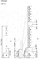
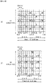
- FIG. 1 shows the structure of a radio frame in a wireless communication system to which an embodiment of the present invention may be applied.
- 3GPP LTE/LTE-A support a radio frame structure type 1 which may be applicable to Frequency Division Duplex (FDD) and a radio frame structure which may be applicable to Time Division Duplex (TDD).
- FDD Frequency Division Duplex
- TDD Time Division Duplex
- FIG. 1(a) illustrates the radio frame structure type 1.
- a radio frame consists of 10 subframes.
- One subframe consists of 2 slots in a time domain.
- the time taken to send one subframe is called a Transmission Time Interval (TTI).
- TTI Transmission Time Interval
- one subframe may have a length of 1 ms, and one slot may have a length of 0.5 ms.
- One slot includes a plurality of Orthogonal Frequency Division Multiplexing (OFDM) symbols in the time domain and includes a plurality of Resource Blocks (RBs) in a frequency domain.
- OFDM symbols are used to represent one symbol period because OFDMA is used in downlink.
- An OFDM symbol may be called one SC-FDMA symbol or symbol period.
- An RB is a resource allocation unit and includes a plurality of contiguous subcarriers in one slot.
- FIG. 1(b) illustrates the frame structure type 2.
- the radio frame structure type 2 consists of 2 half frames. Each of the half frames consists of 5 subframes, a Downlink Pilot Time Slot (DwPTS), a Guard Period (GP), and an Uplink Pilot Time Slot (UpPTS). One subframe consists of 2 slots.
- the DwPTS is used for initial cell search, synchronization, or channel estimation in UE.
- the UpPTS is used for channel estimation in an eNB and to perform uplink transmission synchronization with UE.
- the guard period is an interval in which interference generated in uplink due to the multi-path delay of a downlink signal between uplink and downlink is removed.
- an uplink-downlink configuration is a rule showing how uplink and downlink are allocated (or reserved) with respect to all of subframes.
- Table 1 shows the uplink-downlink configuration.
- Uplink-Downlink configuration Downlink-to-Uplink Switch-point periodicity Subframe number 0 1 2 3 4 5 6 7 8 9 0 5ms D S U U U D S U U U 1 5ms D S U U D D S U U D 2 5ms D S U D D D S U D D 3 10ms D S U U U D D D D D 4 10ms D S U U D D D D D D 5 10ms D S U D D D D D D D 6 5ms D S U U U U D S U U D S U U D
- D indicates a subframe for downlink transmission
- U indicates a subframe for uplink transmission
- S indicates a special subframe including the three fields of a downlink pilot time slot (DwPTS), a guard period (GP), and an uplink pilot time slot (UpPTS) for each of the subframes of the radio frame.
- DwPTS downlink pilot time slot
- GP guard period
- UpPTS uplink pilot time slot
- the uplink-downlink configuration may be divided into seven types. The location and/or number of downlink subframes, special subframes, and uplink subframes are different in the seven types.
- a point of time at which a change is performed from downlink to uplink or a point of time at which a change is performed from uplink to downlink is called a switching point.
- the periodicity of the switching point means a cycle in which an uplink subframe and a downlink subframe are changed is identically repeated. Both 5 ms and 10 ms are supported in the periodicity of a switching point. If the periodicity of a switching point has a cycle of a 5 ms downlink-uplink switching point, the special subframe S is present in each half frame. If the periodicity of a switching point has a cycle of a 5 ms downlink-uplink switching point, the special subframe S is present in the first half frame only.
- No. 0 and No. 5 subframes and DwPTSs are an interval for only downlink transmission.
- the UpPTSs, the subframes, and a subframe subsequent to the subframes are always an interval for uplink transmission.
- Such uplink-downlink configurations may be known to both an eNB and UE as system information.
- An eNB may notify UE of a change of the uplink-downlink allocation state of a radio frame by transmitting only the index of uplink-downlink configuration information to the UE whenever the uplink-downlink configuration information is changed.
- configuration information is kind of downlink control information and may be transmitted through a Physical Downlink Control Channel (PDCCH) like other scheduling information.
- Configuration information may be transmitted to all UEs within a cell through a broadcast channel as broadcasting information.
- PDCCH Physical Downlink Control Channel
- Table 2 shows a configuration (i.e., the length of a DwPTS/GP/UpPTS) of the special subframe.
- Table 2 Special subframe configuration Normal cyclic prefix in downlink Extended cyclic prefix in downlink DwPTS UpPTS DwPTS UpPTS Normal cyclic prefix in uplink Extended cyclic prefix in uplink Normal cyclic prefix in uplink Extended cyclic prefix in uplink 0 6592 ⁇ T s 2192 ⁇ T s 2560 ⁇ T s 7680 ⁇ T s 2192 ⁇ T s 2560 ⁇ T s 1 19760 ⁇ T s 20480 ⁇ T s 2 21952 ⁇ T s 23040 ⁇ T s 3 24144 ⁇ T s 25600 ⁇ T s 4 26336 ⁇ T s 7680 ⁇ T s 4384 ⁇ T s 5120 ⁇ T s 5 6592 ⁇ T s 4384 ⁇ T s 5120 ⁇ T s 20480 ⁇ T s 6 19760 ⁇ T s 23040 ⁇ T
- the structure of a radio frame is only one example.
- the number of subcarriers included in one radio frame, the number of slots included in a subframe, and the number of OFDM symbols included in one slot may be changed in various ways.
- FIG. 2 is a diagram illustrating a resource grid for one downlink slot in a wireless communication system to which the present invention may be applied.
- one downlink slot includes the plurality of OFDM symbols in a time domain.
- one downlink slot includes 7 OFDM symbols and one resource block includes 12 subcarriers in the frequency domain, but the present invention is not limited thereto.
- Each element on the resource grid is referred to as a resource element, and one resource block (RB) includes 12 ⁇ 7 resource elements.
- the number of RBs NDL included in a downlink slot depends on a downlink transmission bandwidth.
- a structure of an uplink slot may be the same as that of a downlink slot.
- FIG. 3 shows a structure of a downlink subframe in a wireless communication system to which an embodiment of the present invention may be applied.
- a maximum of three OFDM symbols located in a front portion of a first slot of a subframe correspond to a control region in which control channels are allocated, and the remaining OFDM symbols correspond to a data region in which a physical downlink shared channel (PDSCH) is allocated.
- Downlink control channels used in 3GPP LTE include, for example, a physical control format indicator channel (PCFICH), a physical downlink control channel (PDCCH), and a physical hybrid-ARQ indicator channel (PHICH), and the like.
- a PCFICH is transmitted in the first OFDM symbol of a subframe and carries information about the number of OFDM symbols (i.e., the size of a control region) which is used to transmit control channels within the subframe.
- a PHICH is a response channel for uplink and carries an acknowledgement (ACK)/not-acknowledgement (NACK) signal for a Hybrid Automatic Repeat Request (HARQ).
- Control information transmitted in a PDCCH is called Downlink Control Information (DCI).
- DCl includes uplink resource allocation information, downlink resource allocation information, or an uplink transmission (Tx) power control command for a specific UE group.
- a PDCCH may carry information about the resource allocation and transport format of a downlink shared channel (DL-SCH) (this is also called an "downlink grant”), resource allocation information about an uplink shared channel (UL-SCH) (this is also called a “uplink grant”), paging information on a PCH, system information on a DL-SCH, the resource allocation of a higher layer control message, such as a random access response transmitted on a PDSCH, a set of transmission power control commands for individual UE within specific UE group, and the activation of a Voice over Internet Protocol (VoIP), etc.
- a plurality of PDCCHs may be transmitted within the control region, and UE may monitor a plurality of PDCCHs.
- a PDCCH is transmitted on a single Control Channel Element (CCE) or an aggregation of some contiguous CCEs.
- CCE is a logical allocation unit that is used to provide a PDCCH with a coding rate according to the state of a radio channel.
- a CCE corresponds to a plurality of resource element groups.
- the format of a PDCCH and the number of available bits of a PDCCH are determined by an association relationship between the number of CCEs and a coding rate provided by CCEs.
- a base station determines the format of a PDCCH based on DCI to be transmitted to UE and attaches a Cyclic Redundancy Check (CRC) to control information.
- CRC Cyclic Redundancy Check
- a unique identifier (a Radio Network Temporary Identifier (RNTI)) is masked to the CRC depending on the owner or use of a PDCCH. If the PDCCH is a PDCCH for specific UE, an identifier unique to the UE, for example, a Cell-RNTI (C-RNTI) may be masked to the CRC. If the PDCCH is a PDCCH for a paging message, a paging indication identifier, for example, a Paging-RNTI (P-RNTI) may be masked to the CRC.
- P-RNTI Paging-RNTI
- the PDCCH is a PDCCH for system information, more specifically, a System Information Block (SIB), a system information identifier, for example, a System Information-RNTI (SI-RNTI) may be masked to the CRC.
- SI-RNTI System Information-RNTI
- a Random Access-RNTI (RA-RNTI) may be masked to the CRC in order to indicate a random access response which is a response to the transmission of a random access preamble by UE.
- FIG. 4 shows a structure of an uplink subframe in a wireless communication system to which an embodiment of the present invention may be applied.
- the uplink subframe may be divided into a control region and a data region in a frequency domain.
- a physical uplink control channel (PUCCH) carrying uplink control information is allocated to the control region.
- a physical uplink shared channel (PUSCH) carrying user data is allocated to the data region.
- PUCCH physical uplink control channel
- PUSCH physical uplink shared channel
- a Resource Block (RB) pair is allocated to a PUCCH for one UE within a subframe. RBs belonging to an RB pair occupy different subcarriers in each of 2 slots. This is called that an RB pair allocated to a PUCCH is frequency-hopped in a slot boundary.
- FIG. 5 illustrates a self-contained subframe structure to which the present invention may be applied.
- the self-contained subframe structure as shown in FIG. 5 has been considered in 5 Generation new RAT.
- the shaded area in FIG. 5 shows a downlink control region, and the dark area shows an uplink control region.
- the area not marked in FIG. 5 may be used for a downlink (DL) data transmission or an uplink (UL) data transmission.
- DL downlink
- UL uplink
- a DL transmission and a UL transmission may be sequentially progressed in a subframe, a DL data may be transmitted and a UL ACK/NACK may be received in a subframe. Consequently, a time required for retransmitting data is reduced when a data transmission error occurs, and owing to this, the delay till the last data forwarding may be minimized.
- the self-contained subframe structure which may be configured/setup in a system operating based on New RAT
- the following at least four subframe types may be considered.
- the durations existed in each of the subframe types are numerated in time sequence.
- a time gap is required for a process that an eNB and a UE switch from a transmission mode to a reception mode or a process that an eNB and a UE switch from a reception mode to a transmission mode.
- a part of OFDM symbols on the timing switching from DL to UL may be setup as GP, and such a subframe type may be referred to as 'self-contained SF'.
- mmW millimeter Wave
- a wavelength becomes short and an installation of a plurality of antenna elements is available in the same area. That is, the wavelength in 30 GHz band is 1 cm, and accordingly, an installation of total 100 antenna elements is available in 2-dimensional arrangement shape with 0.5 lambda (wavelength) intervals in 5 by 5 cm panel. Therefore, in mmW band, beamforming (BF) gain is increased by using a plurality of antenna elements, and accordingly, coverage is increased or throughput becomes higher.
- BF beamforming
- each antenna element has a Transceiver Unit (TXRU) such that it is available to adjust a transmission power and a phase, and independent beamforming is available for each frequency resource.
- TXRU Transceiver Unit
- it has a problem that effectiveness is degraded in a cost aspect when TXRUs are installed in all of about 100 antenna elements.
- a method has been considered to map a plurality of antenna elements in a single TXRU and to adjust a direction of beam by an analog phase shifter.
- Such an analog beamforming technique may make only one beam direction throughout the entire band, and there is a disadvantage that frequency selective beamforming is not available.
- B number of hybrid BF may be considered which is smaller than Q number of antenna element.
- directions of beams that may be transmitted simultaneously are limited lower than B number; even it is changed according to a connection scheme between B number of TXRUs and Q number of antenna elements.
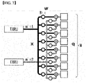
- FIGS. 6 and 7 illustrate a representative connection scheme between a TXRU and an antenna element. More particularly, FIG. 6 exemplifies a sub-array partition model, which is a first TXRU virtualization model option and FIG. 7 exemplifies a full-connection model, which is a second TXRU virtualization model option.
- TXRU virtualization model represents a relation between an output signal of a TXRU and an output signal of an antenna element.
- W represents a phase vector which is multiplied by an analog phase shifter. That is, a direction of analog beamforming is determined by W.
- mapping between CSI-RS antenna ports and TXRUs may be 1 to 1 (1:1) or 1 to many (1:N).
- a signal may be distorted during transmission because data is transmitted through a radio channel.
- the distortion of a received signal needs to be corrected using channel information.
- a method of detecting channel information using the degree of the distortion of a signal transmission method and a signal known to both the transmission side and the reception side when they are transmitted through a channel is mainly used.
- the aforementioned signal is called a pilot signal or reference signal (RS).
- each transmission antenna should have an individual reference signal.
- an RS may be basically divided into two types depending on its purpose.
- the former has a purpose of obtaining, by a UE, to obtain channel state information in the downlink, and accordingly, a corresponding RS should be transmitted in a wideband, and a UE should be capable of receiving and measuring the RS although the UE does not receive downlink data in a specific subframe.
- the former is also used for radio resources management (RRM) measurement, such as handover.
- RRM radio resources management
- the latter is an RS transmitted along with corresponding resources when an eNB transmits the downlink.
- a UE may perform channel estimation by receiving a corresponding RS and thus may demodulate data.
- the corresponding RS should be transmitted in a region in which data is transmitted.
- a downlink RS includes one common RS (CRS) for the acquisition of information about a channel state shared by all of UEs within a cell and measurement, such as handover, and a dedicated RS (DRS) used for data demodulation for only a specific UE.
- CRS common RS
- DRS dedicated RS
- Information for demodulation and channel measurement may be provided using such RSs. That is, the DRS is used only for data demodulation, and the CRS is used for the two purposes of channel information acquisition and data demodulation.
- the reception side measures a channel state based on a CRS and feedbacks an indicator related to channel quality, such as a channel quality indicator (CQI), a precoding matrix index (PMI) and/or a rank indicator (RI), back to the transmission side (i.e., an eNB).
- the CRS is also called a cell-specific RS.
- a reference signal related to the feedback of channel state information (CSI) may be defined as a CSI-RS.
- a UE reports CSI to a BS.
- the CSI is commonly called for the information that may represent a quality of a radio channel (or also referred to as a link) established between a UE and an antenna port.
- the CSI may correspond to a rank indicator (RI), a precoding matrix indicator (PMI), and/or a channel quality indicator (CQI), and the like.
- RI represents rank information of a channel, and this may mean the number of streams that a UE receives through the same time-frequency resource.
- RI is determined with being dependent upon long-term fading of a channel
- the RI is fed back from a UE to a BS with a period longer than CQI, generally.
- PMI is a value that reflects a channel space property, and represents a precoding index that a UE prefers based on a metric such as SINR.
- CQI is a value that represents signal strength, and means a reception SINR that is obtainable when a BS uses the PMI, generally.
- a BS may setup a plurality of CSI processes to a UE, and may receive CSI report for each process.
- the CSI process may include CSI-RS for signal quality measurement from a BS and CSI-interference measurement (CSI-IM) resource for interference measurement.
- CSI-IM CSI-interference measurement
- the DRS may be transmitted through resource elements if data demodulation on a PDSCH is required.
- a UE may receive information about whether a DRS is present through a higher layer, and the DRS is valid only in the case that a corresponding PDSCH has been mapped.
- the DRS may also be called a UE-specific RS or Demodulation RS (DMRS).
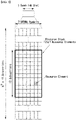
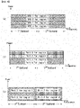
- FIG. 8 illustrates reference signal patterns mapped to downlink resource block pairs in a wireless communication system to which the present invention may be applied.
- a downlink resource block pair a unit in which a reference signal is mapped may be represented in the form of one subframe in a time domain X 12 subcarriers in a frequency domain. That is, in a time axis (an x axis), one resource block pair has a length of 14 OFDM symbols in the case of a normal cyclic prefix (CP) (in FIG. 7(a)) and has a length of 12 OFDM symbols in the case of an extended cyclic prefix (CP) (FIG. 7(b)).
- CP normal cyclic prefix
- FIG. 7(b) an extended cyclic prefix
- resource elements (REs) indicated by '0', '1', '2', and '3' mean the locations of the CRSs of antenna port indices '0', '1', '2', and '3', respectively, and REs indicated by 'D' mean the location of a DRS.
- reference signals for a single antenna port are arrayed.
- reference signals for two transmission antenna ports are arrayed using a time division multiplexing (TDM) scheme and/or a frequency division multiplexing (FDM) scheme. That is, different time resources and/or different frequency resources are allocated in order to distinguish between reference signals for two antenna ports.
- TDM time division multiplexing
- FDM frequency division multiplexing
- Reference signals for four transmission antenna ports are arrayed using the TDM and/or FDM schemes.
- Channel information measured by the reception side (i.e., UE) of a downlink signal may be used to demodulate data transmitted using a transmission scheme, such as single transmission antenna transmission, transmission diversity, closed-loop spatial multiplexing, open-loop spatial multiplexing or a multi-user MIMO antenna.
- a multi-input multi-output antenna when a RS is transmitted by a specific antenna port, the RS is transmitted in the locations of resource elements specified depending on a pattern of the RS and is not transmitted in the locations of resource elements specified for other antenna ports. That is, RSs between different antennas do not overlap.
- an LTE-A system that is, an evolved and developed form of the LTE system
- the design is necessary to support a maximum of eight transmission antennas in the downlink of an eNB.
- RSs for the maximum of eight transmission antennas must be also supported.
- the LTE system only downlink RSs for a maximum of four antenna ports has been defined.
- RSs for these antenna ports must be additionally defined and designed.
- both of the aforementioned RS for channel measurement and the aforementioned RS for data demodulation should be designed.
- the RS newly designed in the LTE-A system is basically divided into two types, which include an RS having a channel measurement purpose for the selection of MCS or a PMI (channel state information-RS, channel state indication-RS (CSI-RS), etc.) and an RS for the demodulation of data transmitted through eight transmission antennas (data demodulation-RS (DM-RS)).
- RS data demodulation-RS
- the CSI-RS for the channel measurement purpose is characterized in that it is designed for a purpose focused on channel measurement unlike the existing CRS used for purposes of measurement, such as channel measurement and handover, and for data demodulation. Furthermore, the CSI-RS may also be used for a purpose of measurement, such as handover.
- the CSI-RS does not need to be transmitted every subframe unlike the CRS because it is transmitted for a purpose of obtaining information about a channel state. In order to reduce overhead of a CSI-RS, the CSI-RS is intermittently transmitted on the time axis.
- a maximum of eight transmission antennas are supported in the downlink of an eNB.
- RSs for a maximum of eight transmission antennas are transmitted in a full band every subframe using the same method as the CRS in the existing LTE, RS overhead is excessively increased.
- an RS has been separated into the CSI-RS of the CSI measurement purpose of the selection of MCS or a PMI and the DM-RS for data demodulation, and thus the two RSs have been added.
- the CSI-RS may also be used for a purpose, such as RRM measurement, but has been designed for a main purpose for the acquisition of CSI.
- the CSI-RS does not need to be transmitted every subframe because it is not used for data demodulation. Accordingly, in order to reduce overhead of the CSI-RS, the CSI-RS is intermittently transmitted on the time axis. That is, the CSI-RS has a period corresponding to a multiple of the integer of one subframe and may be periodically transmitted or transmitted in a specific transmission pattern. In this case, the period or pattern in which the CSI-RS is transmitted may be set by an eNB.
- a UE In order to measure a CSI-RS, a UE should be aware of information about the transmission subframe index of the CSI-RS for each CSI-RS antenna port of a cell to which the UE belongs, the location of a CSI-RS resource element (RE) time-frequency within a transmission subframe, and a CSI-RS sequence.
- RE resource element
- an eNB In the LTE-A system, an eNB has to transmit a CSI-RS for each of a maximum of eight antenna ports. Resources used for the CSI-RS transmission of different antenna ports must be orthogonal. When one eNB transmits CSI-RSs for different antenna ports, it may orthogonally allocate the resources according to the FDM/TDM scheme by mapping the CSI-RSs for the respective antenna ports to different REs. Alternatively, the CSI-RSs for different antenna ports may be transmitted according to the CDM scheme for mapping the CSI-RSs to pieces of code orthogonal to each other.
- the eNB When an eNB notifies a UE belonging to the eNB of information on a CSI-RS, first, the eNB should notify the UE of information about a time-frequency in which a CSI-RS for each antenna port is mapped.
- the information includes subframe numbers in which the CSI-RS is transmitted or a period in which the CSI-RS is transmitted, a subframe offset in which the CSI-RS is transmitted, an OFDM symbol number in which the CSI-RS RE of a specific antenna is transmitted, frequency spacing, and the offset or shift value of an RE in the frequency axis.
- a CSI-RS is transmitted through one, two, four or eight antenna ports.
- a PDSCH transmission is available only to a single analog beam direction on a time by analog beamforming.
- an eNB is able to transmit data only to a small number of UEs in a specific direction.
- analog beam direction is differently configured for each antenna port, and a data transmission may be performed to a plurality of UEs in several analog beam directions simultaneously.
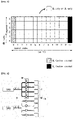
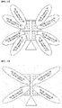
- FIG. 9 is a diagram illustrating a service area for each TXRU.
- each sub-array includes total 64 (8x8) antenna elements in 2-dimensional array shape
- a region corresponding to a horizontal angle area of 15 degrees and a vertical angle area of 15 degrees may be covered by specific analog beamforming. That is, a region in which an eNB is needed to serve is divided into a plurality of areas, and each area is served at a time.
- CSI-RS antenna port and TXRU are mapped in 1-to-1 manner. Accordingly, an antenna port and a TXRU may have the same meaning in the following description.
- the throughput of the corresponding region may be increased by forming a digital beam having higher resolution.
- the throughput of the corresponding region may be increased by increasing rank of transmission data to the corresponding region.
- a simultaneous data transmission becomes available in a corresponding subframe (SF) to UEs distributed in wider area. For example, among four antenna ports, two of them are used for a PDSCH transmission to UE1 in area 1 and the remaining two of them are used for a PDSCH transmission to UE2 in area 2.
- FIG. 9b shows an example that PDSCH 1 transmitted to UE1 and PDSCH 2 transmitted to UE2 are Spatial Division Multiplexed (SDM).
- FIG. 9c shows an example that PDSCH 1 transmitted to UE1 and PDSCH 2 transmitted to UE2 may be transmitted by being Frequency Division Multiplexed (FDM).
- FDM Frequency Division Multiplexed
- a preferred scheme may be changed depending on a RANK and an MCS served to a UE.
- a preferred scheme may also be changed depending on an amount of data to be transmitted to each UE.
- An eNB calculates cell throughput or scheduling metric that may be obtained when serving an area by using all antenna ports, and calculates cell throughput or scheduling metric that may be obtained when serving two areas by dividing antenna ports.
- the eNB compares the cell throughput or the scheduling metric that may be obtained through each scheme, and selects a final transmission scheme. Consequently, the number of antenna ports participated in a PDSCH transmission is changed for each SF (SF-by-SF).
- a CSI feedback from a UE proper to it may be requested.
- BRS Beam reference signal
- BRRS Beam refinement reference signal
- c(i) represents a pseudo-random sequence generator, and may be initialized by Equation 2 on a starting point of each OFDM symbol.
- a transmission and a reception of BRRS may be dynamically scheduled in a downlink resource allocation in xPDCCH.
- BRRS sequence r l,n s ( m ) may be defined as Equation 3 below.
- Equation 3 ns represents a slot number in a radio frame, I represents an OFDM symbol number in the slot, and c(n) represents a pseudo-random sequence.
- the pseudo-random sequence generator may be initialized by Equation 4 on a starting point of each OFDM symbol.
- N ID BRRS may be set to a UE through Radio Resource Control (RRC) signaling.
- RRC Radio Resource Control
- BRS may be transmitted in every subframe, and may be transmitted in different analog beam directions for each port. Such a BRS may be used for an eNB to determine an approximate beam direction for a UE. When an approximate beam direction for a UE is determined based on BRS, an eNB may transmit BRRS for each of more accurate/minute analog beam directions within the determined analog beam direction range, and may determine more accurate analog beam direction.
- the name for the reference signal used for determining an analog beam direction for a UE is not limited to the BRS or the BRRS described above, and it is apparent that the name may be substituted by/referred to various reference signals that are usable for performing the same function.
- the BRS may be substituted by/referred to primary/first CSI-RS, Primary synchronization signal/sequence (PSS), Secondary synchronization signal/sequence (SSS), Synchronization Signal/Sequence (SS) block, NR-PSS, and/or NR-SSS
- the BRRS may be substituted by/referred to secondary/second CSI-RS.
- PL PCRS DL Phase noise compensation reference signal
- the PCRS is existed only in the case that xPDSCH transmission is associated with a corresponding antenna port, and the PCRS in this case may be a valid reference for phase noise compensation.
- the PCRS may be transmitted only in physical resource blocks and symbols to which corresponding xPDSCH is mapped.
- the PCRS may be the same in all symbols that correspond to xPDSCH allocation.
- PCRS sequence r(m) may be defined as Equation 5 below.
- r m 1 2 1 ⁇ 2 ⁇ c 2 m + j 1 2 1 ⁇ 2 ⁇ c 2 m + 1
- m 0,1 , ... , ⁇ N RB max , DL / 4 ⁇ ⁇ 1
- c(i) represents pseudo-random sequence.
- the pseudo-random sequence generator may be initialized by Equation 6 on a starting point of each subframe.
- c init ⁇ n s / 2 ⁇ + 1 ⁇ 2 n ID n SCID + 1 ⁇ 2 16 + n SCID
- n_SCID may be set to 0, unless it is particularly determined.
- n_SCID may be provided by a DCl formation associated with xPDSCH transmission.
- a scheme is considered for demodulating the data using a UE-specific RS like a specific DMRS. Since such a DMRS is transmitted together with scheduled RB(s) of the corresponding PDSCH only and during only a time duration in which a scheduled PDSCH is transmitted, there may be a restriction in reception performance in performing channel estimation only with the corresponding DMRS. For example, for performing channel estimation, an estimation value of major large-scale parameter/property (LSP) of a radio channel is required, and DMRS density may be in short to obtain only the DMRS existed in time/frequency domain through which the scheduled PDSCH is transmitted.
- LSP major large-scale parameter/property
- the following quasi co-location signaling/assumption/behavior between RS ports is defined, and accordingly this, the methods of configuring/operating a UE are supported.
- QC / QCL quadsi co-located or quasi co-location
- UE may assume that the large-scale property of a signal transferred through one antenna port may be inferred from a signal transferred through the other antenna port.
- the large-scale property includes one or more of Delay spread, Doppler spread, Frequency shift, Average received power, and Received timing.
- the large-scale property of a channel of which one symbol is transferred through one antenna port may be inferred from a wireless channel of which one symbol is transferred through the other antenna port.
- the large-scale property includes one or more of Delay spread, Doppler spread, Doppler shift, Average gain, and Average delay.
- the large-scale property of a wireless channel from one antenna port is the same as the large-scale property of a wireless channel from the other antenna port.
- the large-scale property of a wireless channel from one antenna port may be replaced with the large-scale property of a wireless channel from the other antenna port.
- the QC/QCL-related definitions are not distinguished. That is, the QC/QCL concept may comply with one of the definitions.
- the QC/QCL concept definition may be changed in a form in which antenna ports having an established QC/QCL assumption may be assumed to be transmitted at the same location (i.e., co-location) (e.g., UE may assume antenna ports to be antenna ports transmitted at the same transmission point).
- the present invention includes such similar modifications.
- the QC/QCL-related definitions are interchangeably used, for convenience of description.
- UE may not assume the same large-scale property between wireless channels from corresponding antenna ports with respect to non-QC/QCL antenna ports. That is, in this case, UE may perform independent processing on timing acquisition and tracking, frequency offset estimation and compensation, delay estimation, and Doppler estimation for each configured non-QC/QCL antenna port.
- UE may perform the following operations between antenna ports capable of an assuming QC/QCL:
- UE may apply the large-scale property of a wireless channel estimated from its own CRS antenna port upon channel estimation through the corresponding DMRS antenna port, in the same manner, thereby improving reception performance of a DMRS-based downlink data channel.
- UE may perform the detection/reception, channel estimation, and channel state report of a downlink reference signal through a QC/QCL assumption between antenna ports.
- a UE may assume that antenna ports 0-3 of a serving cell and an antenna port for PSS/SSS are in QCL relation for Doppler shift and average delay.
- a UE configured with transmission mode 10 for a given serving cell may be configured with up to four parameter sets by higher layer signaling in order to decode a PDSCH according to detected PDCCH/EPDCCH that has DCl format 2D which is intended for the UE and the given serving cell.
- the UE uses the parameter configured according to 'PDSCH RE Mapping and Quasi-Co-Location indicator' field value, which is described in below Table 3, in the detected PDCCH/EPDCCH that has DCl format 2D.
- the UE uses the parameter set indicated in the PDCCH/EPDCCH that has DCI format 2D corresponding to SPS activation which is associated to determine PDSCH RE mapping and PDSCH antenna port QCL.
- the following parameters for determining PDSCH RE mapping and PDSCH antenna port QCL are configured through higher layer signaling for each parameter set:
- a PDSCH is decoded according to detected PDCCH/EPDCCH having DCI format 1A that has CRC scrambled with C-RNTI intended for a use of a UE and a given serving cell, and a UE is configured with Type B QCL type for PDSCH transmission in antenna port 7, in order to determine PDSCH RE mapping and PDSCH antenna port QCL, a UE to which transmission mode 10 for a given serving cell is set should use parameter set 1 in Table 3.
- a UE to which transmission mode 10 for a given serving cell is set should use parameter set 1 in Table 3 in order to determine PDSCH RE mapping and PDSCH antenna port QCL.
- a UE set to transmission mode 10 for a given serving cell should determine PDSCH RE mapping using the lower indexed zero-power CSI-RS.
- a UE configured with transmission modes 8-10 for a serving cell may assume that antenna ports 7-14 for the serving cell is in QCL for a given subframe for delay spread, Doppler spread, Doppler shift, average gain and average delay.
- a UE configured with transmission modes 1-10 for a serving cell may assume that antenna ports 0-3, 5, 7-30 for the serving cell is in QCL for Doppler shift, Doppler spread, average delay and delay spread.
- a UE configured with transmission mode 10 for a serving cell is configured with one of two QCL types for the serving cell by higher layer parameter QCL operation in order to decode a PDSCH according to a transmission scheme in relation to antenna ports 7-14.
- a UE does not expect that it is configured with QCL type B.
- CSI-RS Channel-State Information
- the UE may be configured with a single CSI-RS resource configuration.
- the UE may be configured with a single CSI-RS resource configuration.
- the UE may be configured with one or more CSI-RS resource configurations.
- the UE may be configured with one or more CSI-RS resource configuration(s).
- the following parameters that the UE assumes non-zero transmission power for a CSI-RS is configured through higher layer signaling for each CSI-RS resource configuration:
- P_c is an assumed ratio of PDSCH EPRE for CSI-RS EPRE when a UE derives CSI feedback and takes a value in a range of [-8, 15] dB with 1 dB step size.
- the PDSCH EPRE corresponds to symbol number for a ratio of the PDSCH EPRE with respect to cell-specific RS EPRE.
- a UE does not expect to a configuration of a CSI-RS and a PMCH in the same subframe of a serving cell.
- a UE does not expect to receive CSI-RS configuration index belonged to set [20 -31] for a normal CP case or set [16 -27] for an extended CP case.
- a UE may assume that CSI-RS antenna port of CSI-RS resource configuration is in QCL for delay spread, Doppler spread, Doppler shift, average gain and average delay.
- a UE configured with transmission mode 10 and QCL type B may assume that antenna ports 0 to 3 associated with qcl-CRS-Info-r11 corresponding to CSI-RS resource configuration and antenna ports 15 to 30 corresponding to CSI-RS resource configuration are in QCL for Doppler shift and Doppler spread.
- a UE configured with transmission 10, configured with higher layer parameter eMIMO-Type and the eMIMO-Type is set to 'class B', in which the number of configured CSI resources is more than one for a single CSI process and having QCL type B does not expect to receive CSI-RS resource configuration for a CSI process that has different value of higher layer parameter qcl-CRS-Info-r11.
- BL/CE UE configured with CEModeA or CEModeB does not expect that it is configured with non-zero transmission power CSI-RS.
- a UE should not assume that two antenna ports are in QCL unless otherwise specified.
- a UE may assume that antenna ports 0 to 3 for a serving cell is in QCL for delay spread, Doppler spread, Doppler shift, average gain and average delay.
- a UE For the purpose of discovery signal-based measurement, a UE should not assume that there is another signal or physical channel except the discovery signal.
- a UE supports discoverySignalsInDeactSCell-rl2
- the UE is configured by discovery signal-based RRM measurement in a carrier frequency applicable to a secondary cell in the same carrier frequency, the secondary cell is inactivated, and the UE is not configured by higher layer in order to receive MBMS in the secondary cell, except a discovery signal transmission, it is assumed that PSS, SSS, Physical Broadcast Channel (PBCH), CRS, PCFICH, PDSCH, PDCCH, EPDCCH, PHICH, DMRS and CSI-RS are not transmitted by the corresponding secondary cell until the subframe in which an activation command is received for the secondary cell.
- PBCH Physical Broadcast Channel
- CRS CRS
- PCFICH Physical Broadcast Channel
- PDSCH Physical Broadcast Channel
- PDCCH Physical Broadcast Channel
- EPDCCH EPDCCH
- PHICH PHICH
- DMRS and CSI-RS are not transmitted by the corresponding secondary cell until the subframe in which an activation command is received for the secondary
- an base station may increase throughput of a system by performing D-beamforming and the like using N (N>>1) antenna ports (or corresponds to "element” according to specific port-to-element virtualization, and hereinafter, commonly referred to as "port" for the convenience of description).
- 3GPP Rel-13 defines CSI-RS operation (or CSI reporting operation, each CSI process may be associated with a single CSI-RS resource and a single CSI-IM resource) of non-precoded scheme defined as Class A and CSI-RS operation (or CSI reporting operation, each CSI process may be associated with one or more CSI-RS resources and one or more CSI-IM resources) of beamformed scheme defined as Class B.
- a base station may configure several CSI-RS resources to a UE in a single CSI process.
- a UE merges each of CSI-RS resources configured in a single CSI process into a single large CSI-RS resource, not regarding it as an independent channel, and feedbacks by calculating/obtaining CSI from the corresponding resource.
- the UE merges the configured three 4-port CSI-RS resources and assumes it as a single 12-port CSI-RS resource. The UE feedbacks by calculating/obtaining CSI using 12-port PMI from the corresponding resource.
- a base station may configure several CSI-RS resources to a UE in a single CSI process. For example, in a single CSI process, a base station may configure eight 4-port CSI-RS resources to a UE. Different virtualizations are applied to the respective eight 4-port CSI-RS, and different beamformings with each other may be applied. For example, assuming the case that vertical beamforming is applied with zenith angle of 100 degrees to a first CSI-RS, vertical beamforming may be applied to second to eighth CSI-RSs with zenith angle difference of 5 degrees, and as a result, vertical beamforming may be applied to the eighth CSI-RS with zenith angle of 135 degrees.
- the UE assumes each of the configured CSI-RS resources as an independent channel, and selects one of the configured CSI-RS resources, and then feedbacks/reports by calculating/obtaining CSI based on the selected resource. That is, a UE may select a CSI-RS resource of which channel is robust among the configured eight 4-port CSI-RS resources, and calculate CSI based on the selected CSI-RS resource, and then report it to the base station. In this case, the UE may report the selected CSI-RS resource through CSI-RS Resource Index (CRI) value. For example, in the case that the first CSI-RS resource channel is the strongest, the UE may set the CSI value to '0' and report it to the base station.
- CRI CSI-RS Resource Index
- K may mean the number of CSI-RS resources existed in the CSI process
- Nk may mean the number of CSI-RS resources of the kth CSI-RS resource.
- K is configured with eight 4-port CSI-RS resources
- K is 8
- Nk is 4 regardless of k value.
- each of the combinations of CSI-RSs may be indicated according to an ascending order of CRI values.
- a UE measures N antenna ports, selects N-port precoder by using the N antenna ports, and then reports the related CSI (PMI, CQI, RI, etc.) to the base station.
- the CSI-RS for a channel measurement of a UE needs to be also increased, and the related codebook size is also increased, and consequently, feedback overhead is also increased.
- the number of CSI-RS ports is in relation to a maximum rank of a UE, rather than the number of antenna ports of a base station, and accordingly, there is an advantage that the CSI-RS ports may be used without big increase of the number of CRI-RSs even in the case that the number of antenna ports is increased.
- a beam selection needs to be performed in a base station, and accordingly, there is a disadvantage that the robustness of beamforming may be degraded in the environment that mobility of a UE is high and a beam of a base station is narrow.
- the hybrid CSI-RS based scheme (or CSI reporting scheme) that uses a combination of Class A and Class B.
- the UE performing the QCL operation in the case that the UE configured with QCL Type B, may use LSPs estimated from a specific QCLed CSI-RS resource indicated a scheduling DCI in order to be assisted with channel estimation of a DMRS transmitted together with scheduled PDSCH.
- aperiodic CSI-RS transmission scheme is considered in the aspect that the transmission of CSI-RS itself is transmitted only when it is required departing from the conventional periodic scheme, and accordingly, there is a problem that the RS density for being utilized as CSI-RS for QCL assumption becomes in short significantly in comparison with the conventional system.
- QCL parameters that may be defined in the NR environment will be described.
- the following QCL parameters are not limited to the NR environment, but may be applied to various wireless communication systems.
- QCL parameters considered in the NR environment, one of the followings may be defined / configured.
- the parameters in relation to a reception beam such as the AA and the AS may be defined as new type of QCL parameters.
- QCL assumption for a reception beam direction is available.
- a UE is available to receive a transmission signal by setting a reception beam direction (and/or reception beam width/sweeping degree) of a transmission signal from other antenna port(s) in the same way as the AA estimated from specific antenna port(s) and in the similar way (in relation to this).
- a reception performance may be guaranteed higher than a specific level.
- Such an AA may also be replaced by a term "(Almost) Dominant arrival angle" and the like, for example.
- the QCL assumption in the AA aspect when assuming that there is a specific dominant (arrival) angle 'S' of a signal measured from a specific antenna port, it may be interpreted that the specific dominant (arrival) angle of a signal measured from other antenna port, which is QCL assumed (or has QCL relation) with this, is "almost" the same as/similar to the 'S'. That is, a receiver may in which QCL assumption is available may utilize/apply the AA estimated from the specific indicated QCLed RS/SS to a reception process almost at it is, and consequently, there is an advantage that an implementation/operation of an efficient receiver is available.
- the QCL assumption in the AS aspect between two antenna ports means that the AS of a specific port may be derived/estimated/applied from the AS estimated from other port which is QCLed with the corresponding port.
- the AS may be distinguished into Azimuth AS and Zenith AS, and in this case, the AS may be separately defined or defined together for each specific dimension. And/or, the AS may be distinguished into departure AS and arrival AS, and may be defined separately or together with for each distinguished AS.
- the QCL assumption for a reception beam width/sweeping degree (and/or a reception beam direction) is available.
- a UE may mean that a reception of a transmission signal is available by configuring a reception beam width/sweeping degree (and/or a reception beam direction) from other antenna port(s) identically or similarly (in relation to it) with the AS estimated from specific antenna port(s).
- a reception performance is guaranteed higher than a specific level.
- the AA may be interpreted as a parameter in relation to average (the most) valid/dominant beam/spatial direction/angle
- the AS may be interpreted as a parameter in relation to beam/space/angle spectrum/range for degree of spreading of beam direction by a reflector distribution (based/centered on AA).
- the AA and AS are parameters used in QCL assumption for a reception beam/space/angle management function. Therefore, the AA and AS may be collectively called a reception beam parameter, a reception beam related parameter, a reception angle parameter, a reception angle related parameter, a spatial QCL parameter, a spatial parameter, or a spatial Rx parameter.
- the AA and AS will be collectively called the 'reception beam related parameter'.
- AoA Angle of Arrival
- Dominant AoA Dominant AoA
- average AoA Power Angular Spectrum
- PAS Power Angular Spectrum
- AoD average Angle of Departure
- PAS of AoD transmit/receive channel correlation
- transmit/receive beamforming spatial channel correlation, and the like
- AA Angle of Arrival
- AS Power Angular Spectrum
- transmit/receive channel correlation transmit/receive beamforming
- spatial channel correlation and the like
- PAP power angle (-of-arrival) profile
- the QCL guarantee/assumption in terms of the PAP may mean, for example, that a received beam width/sweeping degree (and/or received beam direction) when receiving a transmission signal from another antenna port(s) based on the PAP estimated from a specific antenna port(s) is set to be the same as or similar to a corresponding specific antenna port(s) (or associated therewith) to receive the transmission signal. Furthermore, the QCL guarantee/assumption in terms of the PAP may mean that the reception performance in this way is guaranteed at a specific level or higher.
- partial QCL or may also be referred to as a similar/modified name such as sub-QCL, fractional QCL, or quasi-sub-location (QSL)
- QSL quasi-sub-location
- a relationship such as "partial QCL (or may also be referred to as a similar/modified name such as sub-QCL, fractional QCL, or quasi-sub-location (QSL))" may be established/configured/indicated between specific antenna ports with respect to the at least one QCL parameter.
- the "partial QCL" is established between a signal (and/or a resulting experienced/observed (wireless) channel) transmitted from specific antenna port group A (e.g., the number of antenna port groups A may be one or more) and a signal (and/or a resulting experienced/observed (wireless) channel) transmitted from specific antenna port group B (e.g., the number of antenna port groups B may be one or more).
- QCL parameter(s)/property(s) for antenna port group A is a "sub-set (a relationship included in the same or higher set)" of QCL parameter(s)/property(s) estimated from antenna port group B. This may mean that performance is guaranteed at a predetermined level or higher when an association operation is applied based on the assumption/application/utilization.
- the "partial QCL" has significance in various environments.
- a case may be considered in which a plurality of physical antennas form a single antenna network (SFN) to form logical antenna port group A and logical antenna group B is mapped to individual physical antennas. That is, in a representative example, a case may be considered in which a plurality of physical antennas (in particular, when LSPs are different for each physical antenna) is mapped to antenna ports of logical antenna port group A and signals of corresponding antenna ports are transmitted through the plurality of antennas, but antenna ports of logical antenna port group B are mapped to any one of the plurality of physical antennas to which logical antenna port group A is mapped to transmit signals of corresponding ports through the one antenna.
- SFN single antenna network
- a receiving end may derive the LSP of a channel to be experienced/transmitted by the signal transmitted through logical antenna port group B from the SLP of the channel acquired from the signal transmitted through logical antenna port group A (i.e., partial QCL relationship/assumption is established).
- a relationship may be established/assumed in which channel delay values for/affecting the signal transmitted through logical antenna port group B are some of channel delay values for/affecting the signal transmitted through logical antenna port group A.
- a relationship may be established/assumed in which channel Doppler values for/affecting the signal transmitted through logical antenna port group B are some of channel Doppler values for/affecting the signal transmitted through logical antenna port group A.
- the receiving end may configure a parameter/LSP for a channel estimator of the signal received through antenna port group B by using/based on the LSP acquired from the signal of logical antenna port group A by using such relationships.
- a relationship may be established/assumed in which a reception beam direction (or angle/range) for receiving the signal transmitted through logical antenna port group B belongs to/is included in a reception beam direction (or angle/range) for receiving the signal transmitted through logical antenna port group A.
- the receiving end may search the reception beam direction (or angle/range) for receiving the signal transmitted through logical antenna port group B among the reception beam directions (or angles/ranges) for receiving the signal transmitted through logical antenna port group A by using such relationships. Therefore, the receiving end may improve a search speed of the reception beam direction and/or reduce complexity of reception processing.
- At least one of the QCL parameters/properties described above may be supported to be used in a UE operation by being defined/configured between specific RS/SS (e.g., between RS/SS of different types with each other among the RS/SS described below or between RS/SS of the same types).
- RS density is supported such that the QCL assumption is available for a specific QCL parameter/property (e.g., ⁇ Doppler spread and/or Doppler shift ⁇ ) from much higher BRS, and so on.
- QCL parameter/property e.g., ⁇ Doppler spread and/or Doppler shift ⁇
- the RS/SS QCLed with the BRRS may be provided together when the RRC of the corresponding BRRS is configured, and this may mean that semi-static QCL configuration for BRRS is supported. Otherwise, in order to provide more dynamic QCL configuration, QCL configuration of L2-level (and/or L1-level) may be configured/provided through medium access control (MAC) control element (CE) (and/or DCI) and so on for each BRRS.
- MAC medium access control
- CE control element
- all types of QCL configuration information of L2-level (and/or L1-level) may be provided to a UE (in real time) with full flexibility, or a plurality of candidate QCL configuration parameter sets is configured through RRC configuration and a UE is instructed through L2-level (and/or L1-level) signaling about which one is selected/applied/used among the parameter sets.
- QCL configuration may be hierarchized (e.g., through total third times) (or through a plurality of times) and instructed/provided to a UE, and may be instructed through RRC configuration primarily, L2-level signaling (e.g., MAC CE, etc.) secondarily, and L1-level signaling (e.g., DCI, etc.) thirdly.
- hierarchized QCL configuration instruction scheme may be applied to the QCL configuration of other RS/SS in the same/similar manner as well as the QCL configuration of the BRRS.
- the signaling scheme of RS/SS e.g., BRS and/or PSS/SSS
- BRRS e.g., PSS and/or PSS/SSS
- L1 and/or L2-level
- a transmitter may set at least one BRRS (resource(s)) to a receiver in advance, and a transmitter (or an eNB) may instruct information for a receiver to receive each BRRS dynamically through L2-level (e.g., MAC CE) and/or L1-level (e.g., DCI).
- the information for receiving each BRRS may include QCLed RS/SS information (with BRRS), for example, information of specific BRS port(s) and/or specific PSS/SSS.
- a transmitter or an eNB is able to perform a proper (aperiodic/on-demand) BRRS transmission very flexibly by considering an instantaneous situation such as loading of a UE and traffic/channel condition, and the like by using BRRS transport resources that are preconfigured to a UE.
- specific ID may be provided to each BRRS (or BRRS resource) and/or each BRRS port(s), and/or specific ID may be provided to each BRS (or BRS resource) and/or each BRS port(s).
- Such a specific ID may be indicated to a UE through QCL signaling for providing QCL configuration to the UE described above.
- the eNB may restrict QCL parameter/property to which QCL assumption is applied to a part of the numerated QCL parameters/properties.
- a UE may be restricted such that QCL assumption is available only for ⁇ Doppler spread, and/or Doppler shift ⁇ parameter/property. This is caused by the reason such as the case that there is a limitation in obtaining frequency synchronization only with the BRRS safely.
- the QCL assumption between BRRS and a specific BRS may be support by an implementation scheme in the case that BRRS and BRS are generated from the same oscillator.
- a UE may be restricted that QCL assumption is (also) available for ⁇ Delay spread, and/or Average delay ⁇ parameter/property.
- an eNB may configure/support the LSP of BRS QCLed with BRRS to a UE in the case that the LSP is guaranteed when it may be inferred between BRRS and BRS (transmitted from the same panel antenna, etc.), and accordingly, an efficient receiver implementation may be supported.
- a UE may be restricted that QCL assumption is (also) available for ⁇ Average angle and/or Angular spread ⁇ parameter/property.
- a reception (analog) beam coefficients generation for receiving BRRS may be applied by inferring from a beam coefficient generation which is applied when receiving BRS, and accordingly, there is an advantage that an efficient receiver implementation may be supported. Otherwise, considering that the AA of BRRS may be deviated with an angle different from the AA of BRS with a specific level or higher, it may be set to a UE such that only "AS" is reflected (i.e., QCL assumption) (additionally).
- CSI-RS based CSI measurement and reporting operation when a channel for CSI-RS itself is measured, (considering that CSI-RS transmission may have aperiodic property in NR) it is required to support the QCL assumption for specific QCL parameter/property (e.g., Doppler spread and Doppler shift) from BRS or BRRS of which RS density is greater.
- QCL parameter/property e.g., Doppler spread and Doppler shift
- the information of RS/SS which is QCLed may be provided when RRC of the corresponding CSI-RS is configured together, and this may be interpreted that semi-static QCL configuration for CSI-RS is supported.
- the QCL configuration of L2-level (and/or L1-level) through MAC (medium access control) CE (control element)(and/or DCI) may be configured/provided for each CSI-RS (resource).
- all types of QCL configuration information of L2-level (and/or L1-level) may be provided to a UE (in real time) with full flexibility, or a plurality of candidate QCL configuration parameter sets is configured through RRC configuration and a UE is instructed through L2-level (and/or L1-level) signaling about which one is selected/applied/used among the parameter sets.
- QCL configuration may be hierarchical (e.g., through total third times) (or through a plurality of times) and instructed/provided to a UE, and may be instructed through RRC configuration primarily, L2-level signaling (e.g., MAC CE, etc.) secondarily, and L1-level signaling (e.g., DCI, etc.) thirdly.
- hierarchical QCL configuration instruction scheme may be applied to the QCL configuration of other RS/SS in the same/similar manner as well as the QCL configuration of the CSI-RS.
- the signaling scheme of RS/SS e.g., BRS and/or PSS/SSS
- CSI-RS channel estimation/measurement of BRRS through dynamic indication of L1 (and/or L2)-level
- a transmitter may set at least one CSI-RS (resource(s)) to a receiver in advance.
- configuration information e.g., port number/ (# of ports), scrambling ID, time/frequency RE pattern, CSI-RS (RB-level and/or RE-level) density, port subset (actually allocated port), QCLed (with CSI-RS) RS/SS information, and/or subframe period/offset (including one of an aperiodic type, a semi-persistent type, or a periodic type as a CSI-RS transmission time-domain operation) for CSI-RS measurement for each CSI-RS ID (or CSI-RS resource configuration) semi-statically, only a part of information (e.g., port number/ (# of ports), scrambling ID, and/or time/frequency RE pattern) among these may be configured (e.g., through RRC) semi-statically.
- a transmitter may indicate the remaining information elements except the information element semi-statically configured through L2-level (e.g., MAC CE) and/or L1-level (e.g., DCI).
- the remaining information elements may include QCLed (with CSI-RS) RS/SS information, and may include a specific BRS/BRRS port(s), a specific PSS/SSS, CSI-RS (RB-level and/or RE-level, time-domain/symbol) density value(s), and/or information on one of an aperiodic type, a semi-persistent type, or a periodic type as a CSI-RS transmission time-domain operation, for example.
- semi-static configuration may mean that a specific set among preconfigured candidate parameter sets is dynamically selected.
- a transmitter or an eNB is able to perform a proper (aperiodic/on-demand) CSI-RS transmission very flexibly by considering an instantaneous situation such as loading of a UE and traffic/channel condition, and the like by using CSI-RS transport resources that are preconfigured to a UE.
- At least one CSI-RS (resource(s)) configured to a UE in semi-static manner may be interpreted as at least one "CSI-RS container(s) each with corresponding ID".
- transmission of each "CSI-RS container" on which aperiodic/"on-demand" CSI-RS is carried has an advantage that efficiency of using CSI-RS transport resource is maximized such that an eNB indicates optimal beamforming and QCLed RS/SS dynamically associated with the corresponding CSI-RS on every transmission time.
- a UE may be configured with a specific CSI-RS resource (for BM with 1-port).
- the specific CSI-RS resource may be basically configured with an aperiodic, semi-persistent or periodic CSI-RS resource.
- a CSI-RS resource for BM may be configured/indicated so that it is associated with BM-related reporting (setting) and a UE performs the best beam(s)-related reporting (periodically) in a BM process.
- a UE may measure the CSI-RS resources, and may report a specific beam strength-related metric (e.g., L1 RSRP) at that time along with the reporting of a specific CSI-RS resource ID(s) corresponding to the best beam(s).
- a specific beam strength-related metric e.g., L1 RSRP
- L1 RSRP specific beam strength-related metric
- each CSI-RS resource for BM may have been configured as a relatively long-term transmission and/or low (RB/RE-level) density.
- At least one CSI-RS resource (for BM) may have already been configured/indicated as a beam indication purpose for a specific NR-PDCCH (e.g., for each control-resource set (CORESET)).
- a UE performs BM-related reporting for a plurality of CSI-RS resources for BM, that is, the measurement object of BM-related reporting, and at the same time, at least one specific CSI-RS resource(s) for BM of the plurality of CSI-RS resources for BM may have been (respectively) configured/associated with a specific NR-PDCCH (e.g., CORESET).
- the UE when the UE attempts (DCI) detection/reception by monitoring a specific NR-PDCCH/CORESET, the UE may be supported to attempt the detection/reception by (identically) applying reception beam setting applied when a specific CSI-RS resource(s) for BM configured/associated with a corresponding specific NR-PDCCH/CORESET is received (beam used in this case may be referred to as a 'serving-beam').
- a specific CSI-RS resource(s) for BM associated with at least one specific NR-PDCCH/CORESET (as a beam indication purpose) may be configured/indicated as a relatively short-term transmission and/or high (RB/RE-level) density.
- a base station may configure/indicate/update an operation for configuring/indicating/updating such a beam indication (associated with a specific NR-PDCCH/CORESET) as dynamic indication based on MAC CE (e.g., L2) and/or DCI (e.g., L1) signaling not an RRC level.
- MAC CE e.g., L2
- DCI e.g., L1
- the base station when the base station provides signaling newly configured/indicated/updated as a specific serving beam with respect to a specific CSI-RS resource for BM (not configured as a serving beam so far), the base station may configure/indicate/update the (RB/RE-level) density of a corresponding CSI-RS resource for BM as a higher value or may newly configure/indicate/update a specific time-domain operation-related parameter(s) (e.g., a subframe periodicity/offset and/or one of an aperiodic, semi-persistent or periodic type of CSI-RS transmission).
- a specific time-domain operation-related parameter(s) e.g., a subframe periodicity/offset and/or one of an aperiodic, semi-persistent or periodic type of CSI-RS transmission.
- a base station may change an aperiodic type resource into a semi-persistent/periodic type (because it is a serving-beam) or may lower transmission periodicity (because it is a serving-beam) and frequently transmit a resource.
- a CSI-RS through the specific serving beam may be used for the purpose of an RS (e.g., tracking RS (TRS)) of a tracking purpose for measuring/estimating/deriving at least one QCL parameter, through the configuration/indication/update of the parameter(s).
- TRS tracking RS
- time-domain RS density may be configured/indicated/updated as a sufficient level so that the number of corresponding RS samples appears twice or more within one slot.
- the QCL assumption different from RS/SS may be configured/indicated independently for each CSI-RS resource to at least one CSI-RS resource set to a receiver (or UE). For example, assuming that CSI-RS #1 and #2 are set to a UE, it may be configured/indicated that CSI-RS #1 is QCL-assumed with specific BRS, and CSI-RS #2 is QCL-assumed with specific BRRS.
- CSI-RS #1 may correspond to non-precoded CSI-RS, and/or CSI-RS for CSI-RS measurement initial step (e.g., CSI-RS #1 for hybrid CSI reporting based on CSI-RS #1 and #2), and in this case, it may be configured/indicated that CSI-RS #1 is QCLed with specific BRS.
- CSI-RS #2 may correspond to CSI-RS #2 configured for the purpose of link adaptation for improving transmission efficiency by an eNB in a state that beamformed CSI-RS, and/or a UE access a specific BRS using serving-beam and progress beam refinement sufficiently through (subsequent) BRRS, and in this case, CSI-RS #2 may be QCL configured/indicated with BRRS, not BRS.
- QCL assumption may be configured/indicated between a plurality of CSI-RS resources (for at least reception beam related parameters).
- the UE may assume the QCL relation between antenna ports of CSI-RS #1 and #2 (at least reception beam related parameters).
- a receiver (or a UE) may be configured/indicated with QCL assumption between antenna ports in a single CSI-RS resource. For example, in the case that CSI-RS #1 is set to a UE, the UE may assume the QCL relation between antenna ports corresponding to CSI-RS #1.
- QCL assumption with either one of BRS or BRRS may be selectively configured/indicated to a CSI-RS.
- the present invention is not limited thereto, but according to an embodiment, QCL assumption for both of BRS and BRRS may be configured/indicated to a CSI-RS, and a method of maximizing QCL RS density may also be supported together.
- the eNB may restrict QCL parameter/property to which QCL assumption is applied to a part of the numerated QCL parameters/properties.
- a UE may be restricted such that QCL assumption is available only for ⁇ Doppler spread, and/or Doppler shift ⁇ parameter/property. This is caused by the reason such as the case that there is a limitation in obtaining frequency synchronization only with the CSI-RS safely.
- a UE may be restricted that QCL assumption is (also) available for ⁇ Average angle and/or Angular spread ⁇ parameter/property. This is because it is beneficial to reflect more stable beam with to CSI-RS reception process. Furthermore, when a beam width of CSI-RS is narrow, it may be set to a UE such that only "AS" is reflected (i.e., QCL assumption) (additionally).
- a UE may be restricted that QCL assumption is (also) available for ⁇ Delay spread, and/or Average delay ⁇ parameter/property. This is because it is beneficial to reflect the QCL parameter such as BRS transmitted with wider band than CSI-RS transmission bandwidth to the CSI-RS reception process, considering the case that CSI-RS is transmitted with CSI-RS transmission bandwidth which is limited to a part of band.
- DMRS-based PDSCH/EPDCCH When a UE is trying to receive DMRS-based PDSCH/EPDCCH, and the like, the channel estimation for DMRS is required, QCL assumption/signaling with a specific CSI-RS, BRRS, and/or BRS may be supported for such DMRS.
- CSI-RS density is sufficient (by an eNB), it may be configured/indicated that only QCL between DMRS and specific CSI-RS resource(s) is applied.
- DMRS may be supported with QCL of other RS in which RS density is stably guaranteed in comparison with CSI-RS.
- DMRS may be QCLed with specific BRS, BRRS and/or PCRS, and direct QCL signaling indicating such QCL configuration may be supported in a UE. At this time, the direct QCL signaling may be indicated to a UE even for specific CSI-RS resource(s), PSS and/or SSS together/additionally as well as the RS.
- an inter-RS/SS QCL relationship may be defined/configured in the format in which QCL application is available between independent/separated/different RS and/or SS for specific/individual QCL parameter. That is, when a UE assumes/applies QCL, the UE may distinguish/change the applied QCL parameter according to RS/SS types that are QCLed with DMRS.
- a UE may be configured/indicated so as to assume/apply QCL limitedly only for ⁇ Delay spread, Average delay, Average angle, Angular spread, and/or Average gain ⁇ parameter/property.
- a UE may be configured/indicated so as to assume/apply QCL limitedly only for ⁇ Doppler spread, and/or Doppler shift ⁇ . This is because there is a limitation in estimating/applying ⁇ Doppler spread, and/or Doppler shift ⁇ parameter/property based on CSI-RS only.
- a UE may be configured/indicated so as to assume/apply QCL limitedly only for ⁇ Delay spread, Average delay, Average angle, Angular spread, and/or Average gain ⁇ parameter/property.
- a UE may be configured/indicated so as to assume/apply QCL limitedly only for ⁇ Doppler spread, and/or Doppler shift ⁇ . This embodiment is applicable to the case that it guarantees more stable performance to estimate/apply ⁇ Doppler spread, and/or Doppler shift ⁇ parameter/property from PSS/SSS.
- a UE may be configured/indicated so as to assume/apply QCL limitedly only for ⁇ Delay spread, Average delay, Average angle, Angular spread, and/or Average gain ⁇ parameter/property.
- a UE may be configured/indicated so as to assume/apply QCL limitedly only for ⁇ Doppler spread, and/or Doppler shift ⁇ parameter/property.
- QCL assumption is applicable for all (or most of) QCL parameters/properties, and simultaneously, in the case of specific CSI-RS resource(s), QCL assumption is applicable only for a part of limited QCL parameters/properties (e.g., except ⁇ Doppler spread, and/or Doppler shift ⁇ ).
- an eNB may differently configure/indicate applicable range of QCL parameter/property for each RS/SS, and a part of multiple RSs/SSs are configured/indicated to be QCL-assumed with the same QCL parameter/property, and accordingly available number of RS samples may be more increased.
- the most direct QCL application may be implemented in the form that a priority is provided to a specific RS (e.g., CSI-RS), but QCL application from other RS (e.g., BRS, BRRS, and/or PCRS) may be considered together through weighted average, and the like.
- a priority is provided to a specific RS (e.g., CSI-RS)
- QCL application from other RS e.g., BRS, BRRS, and/or PCRS
- different QCL configuration/indication may be applied to each specific DMRS port(s). For example, in the case that a UE is indicated with DMRS ports 7 to 10 (through DL scheduling grant), the UE may be indicated such that the UE is available to be QCL-assumed with specific ⁇ BRS(s), BRRS(s), PCRS, and/or CSI-RS ⁇ for DMRS ports 7 and 8 among these, and available to be QCL-assumed with specific ⁇ BRS(s), BRRS(s), PCRS, and/or CSI-RS ⁇ for DMRS ports 9 and 10.
- DMRS ports ⁇ 7 and 8 ⁇ and ⁇ 9 and 10 ⁇ may be transmitted from different Transmission Reception Points (TRPs), or transmitted from different antenna panels even in the same TRP, as a matter of fact. Through this, (non-coherent) joint transmission of various forms may be efficiently supported.
- TRPs Transmission Reception Points
- DMRS is QCLed with specific CSI-RS
- the corresponding CSI-RS is QCLed with specific BRS
- both of the DMRS QCL and the CSI-RS QCL are dynamically indicated by (separate) L1-level signaling (e.g., signaling by DCI).
- L1-level signaling e.g., signaling by DCI.
- a timeline issue for the timing when the DMRS is QCL-assumed with the transmitted CSI-RS may occur.
- a timeline issue may occur that QCL with the CSI-RS transmitted on a certain time is applied to DMRS reception/measurement.
- PCRS is an RS defined for the purpose of phase drift adjustment/phase tracking, and may be transmitted with DMRS.
- a DMRS per each DMRS port group in which a plurality of DMRS ports is included may be interlinked with a single PCRS (e.g., has QCL/GCL relationship).
- PCRS may also be referred as Phase Tracking (PT)-RS.
- PT Phase Tracking
- DMRS may also be referred to as a Primary DMRS or a Secondary DMRS (or PT-RS), and PCRS may also be referred to as a Secondary DMRS or a Primary PCRS (or PT-RS).
- GCL gene co-location
- a UE may interpret that 'GCLed (or having GCL relationship) ports are treated as the same port, and available to be specific time bundling and/or frequency bundling is available'. That is, in other words, an assumption of the same precoding is available to a UE by treating the ports in the GCL relationship as the same port, actually.
- PCRS may be defined/configured/indicated so as to be GCL-assumed with DMRS, and in this case, a UE may treat/regard the PCRS port and the DMRS port as the same port, and assume that the same procoding is applied to two antenna ports.
- a scheme is also available that the QCL required to receive/measure PCRS is divided from the QCL of DMRS transmitted/scheduled together, and separate/independent QCL signaling is provided.
- separately divided QCL signaling may be provided separately for each RS through DCI.
- QCL signaling for PCRS may be separated so as to be provided in semi-static scheme relatively than QCL signaling for DMRS.
- QCL signaling for PCRS may be provided L2-level signaling through MAC CE, and so on, and/or RRC signaling, and the like.
- DMRS may be configured/indicated such that QCL assumption is available with specific CSI-RS (and/or BRS and/or BRRS), or PCRS may be configured/indicated such that QCL assumption is available with specific (serving) BRS (and/or BRRS).
- (QCLed/GCLed) (specific) RS/SS may be implicitly indicated to be RS/SS for serving-cell/TP/beam, specifically. That is, a UE may be defined/configured such that the (QCLed/GCLed) (specific) RS/SS is RS/SS for RS/SS for serving-cell/TP/beam, and apply the QCL assumption therefor.
- an eNB configures RRC with QCL type B for CoMP operation such that a UE may perform dynamic point selection (DPS) operation, and an eNB configures RRC with QCL type A for non-CoMP operation such that a UE applies QCL among all RSs in a serving cell with each other.
- DPS dynamic point selection
- FIG. 10 illustrates an antenna panel model in which analog beamforming is applied for each panel to which the present invention may be applied.
- QCL type B' in which a receiver may support such an operation is defined/configured, and accordingly, the receiver may perform beam-based CoMP operation like DBS smoothly.
- QCL type A' may be supported as a mode in which QCL assumption may be applied between RSs that correspond to serving cell/TP/beam.
- QCL type switching may be defined/configured in the following forms.
- a UE to which transmission mode x for serving cell/TP/beam is configured may be configured with one of the following QCL types below for serving cell/TP/beam by higher layer parameter, in order to decode PDSCH according to a transmission scheme associated with antenna ports (e.g., ports 7-14) in relation to DMRS.
- QCL type B' among the configurable QCL types is replaced by QCL type C' described below, it is limitedly defined such that semi-static switching between QCL type A' and QCL type C' only is available, or all of QCL types A' to C1' are defined and a single type is selectively configured by RRC signaling, and the like.
- QCL types A to C may be modified/defined such that the QCL related proposal element proposed in the present invention is reflected in various manners. That is, when QCL type is switching by setting A' and B' or QCL type C that indicates direction QCL with specific BRS is supported (together/additionally) in addition to QCL type A' and B', in the detailed description including the applicable QCL type/property, the technical element proposed in the present invention may be reflected/substituted and defined/modified/defined.
- RSs are referred to as BRS, BRRS, PCRS, and the like, for the convenience of description, but the application of the present invention is not limited thereto, but it is apparent that the present invention may also be applied to RS of other term having the same/similar form/function/purpose of the corresponding RS.
- control information configured/indicated in a UE/receiver may be forwarded by RRC, MAC CE, and/or DCI, and a form of signaling among signaling of such L1 and/or L2 level in which the corresponding configuration/indication is provided may be defined/configured differently/independently for each individual control information.
- single/multi point transmission may be supported for both of DL MIMO and UL MIMO.
- a measurement assumption for QCL assumption and antenna ports may be performed. Based on this, hereinafter, intra/inter-TRP coordination transmission in which QCL is assumed between specific RSs will be described below.
- a first panel model may be distinguished as a uniform 1D/2D rectangular panel array. Since a proper CSI-RS resource/port should be configured with a UE through such antenna array, an efficient closed-loop MIMO transmission may be applied based on the CSI measurement and feedback of a UE.
- CSI-RS port and antenna array mapping are dependent upon eNB implementation and various mapping schemes may be existed, for example, the following schemes may be exited: (1) a CSI-RS resource per panel, (2) a plurality of CSI-RS resources per panel, and (3) CSI-RS resource mapped to a plurality of panel, is mapped.
- FIG. 11 illustrates a scheme in which a single CSI-RS resource is mapped per panel according to an embodiment of the present invention.
- the embodiment shown in FIG. 11 shows the simplest method of CSI-RS mapping that a CSI-RS resource is transmitted in a panel and CSI-RS ports in CSI-RS resource may be QCL-guaranteed/assumed. That is, according to this embodiment, between (a part or all) CSI-RS ports in a single CSI-RS resource, the QCL may be assumed/guaranteed for at least a part (e.g., parameter in relation to average gain, delay spread, Doppler spread, Doppler shift, average delay and/or reception beam) among the QCL parameters/properties described above. Such QCL assumption/guaranteeing may be performed in the case that the same oscillator (having related component) in order to generate a signal in CSI-RS ports (included in a single CSI-RS resource or mapped to a single panel).
- the same oscillator having related component
- This may be interpreted as a single (virtual) cell operation according to the conventional art, and the single virtual cell may be associated with a UE by measuring an RS port that corresponds to Radio resource management (for the convenience of description, hereinafter, referred to as 'RRM-RS').
- Radio resource management for the convenience of description, hereinafter, referred to as 'RRM-RS'.
- FIG. 12 illustrates a scheme in which a plurality of CSI-RS resources is mapped per panel according to an embodiment of the present invention.
- the embodiment shown in FIG. 12 may be interpreted as multiple beamformed CSI-RS based operation similar to Full Dimension (FD)-MIMO class B having multiple Beamformed (BF) CSI-RS resources. Since such a plurality of CSI-RSs transmitted from a single panel is oriented to different beam directions, it cannot say that each CSI-RS and the corresponding RRM-RS are in QCL always for all QCL properties/parameters. Similar to the definition in LTE specification, in the QCL assumption between CSI-RS and RRM-RS for this case, for example, only a part of properties/parameters such as Doppler shift and Doppler spread may be used, and this may be explicitly indicated. Since such a difference is caused by different CSI-RS mapping scheme for antenna array, NR specification should support various implementation schemes of CSI-RS antenna port mapping of different purposes properly.
- FD Full Dimension
- BF Beamformed
- FIG. 13 illustrates a scheme in which CSI-RS resource shared by a plurality of panels is mapped according to an embodiment of the present invention.
- the embodiment shown in FIG. 13 may be interpreted as the shared CSI-RS resource which is mapped to a plurality of panels so as to have more beamforming gain in the CSI-RS transmitted by cooperative transmission from a plurality of panel antennas.
- Such a scheme in which CSI-RS port is mapped to a plurality of panels may be particularly useful for the case of intended to support SU-MIMO transmission for a specific UE in which traffic load is small.
- the CSI-RS may be used as a UE-specific beamformed CSI-RS dedicated to the UE.
- QCL assumption when QCL assumption is required, it is required to examine the QCL assumption between CSI-RS and RRM-RS and the way of definition or support of signaling for NR operation.
- various intra-TRP coordination transmission scheme may be considered in NR.
- a proper QCL assumption between RS(s) for RRM and CSI-RS(s) set to a UE may be required to support the intra-TRP coordination transmission.
- QCL assumption between different antenna ports is required in NR in order to improve channel estimation performance
- different QCL types and similar semi-static configurations may be supported such as being defined in LTE specification (UE of TM 10 is configured with QCL type A or B by RRC signaling).
- each UE may be configured with specific CSI-RS resource(s) that has a few essential RRC parameters, but actual CSI-RS transmission may be controlled by an eNB through L1-signaling.
- the controllable component may include actual transmission instance, time/frequency RE pattern, number of ports, applied port numbering and/or scrambling seed.
- Such a dynamic CSI-RS allocation and transmission may require support of more flexible QCL signaling with other RS that includes RRM-RS in more dynamic scheme. That is, dynamic CSI-RS allocation and transmission for NR may require more flexible QCL signaling support for other RS that includes RRM-RS.
- a UE may select several TX-RX analog beam pair by measuring and comparing a quality of specific DL RS (for the convenience of description, referred to as 'RRM-RS').
- An eNB (or may be referred to as gNB) may select one of UE-preferred transmission (TX) beams in order to transmit beamformed CSI-RS or DMRS ports.
- TX transmission
- the UE should know which reception (RX) beam receives these antenna ports among candidate RX beams such that the TX beam ID corresponding to RRM-RS port is to be signaled to the UE.
- RRM-RS port and the CSI-RS/DMRS port are QCLed in the aspect of dominant arrival angle according to the QCL definition as below.
- the Dominant arrival angle may determine an RX beam formation coefficient.
- the Dominant arrival angle may be regarded as LSP relatively. Without QCL assumption, a UE should search a plurality of RX beam candidates, and this is time and frequency-consuming.
- the reception beam related parameter described above may be defined as a new type of QCL parameter.
- RRM-RS in order to assist RRM-RS measurement, it should be considered whether a part (e.g., Doppler shift and average delay) of QCL parameters/properties obtained from synchronization signals is QCL-assumed for RRM-RS.
- a UE tracks such RRM-RS(s) once, this may be used for QCL linkage of the second level of RRM-RS for minuter beam refinement which may be UE-specifically beamformed for the UE.
- CSI-RS follows QCL linkage for primary or secondary RRM-RS(s).
- sub band CSI-RS is set to a UE, for example, it may be beneficial to follow QCL for other CSI-RS which is transmitted in broadband.
- a UE to which TM10 having QCL type B is configured may be scheduled to receive a PDSCH transmitted from a non-serving cell/TP as CoMP Dynamic point selection (DPS) operation.
- DPS CoMP Dynamic point selection
- the DMRS for a PDSCH may be instructed to follow at least one of CSI-RSs configured by PQI filed in a DCI and QCL.
- the DMRS for a PDSCH may be configured to have QCL relation with at least one of CSI-RSs indicated by PQI field.
- a similar operation to the DPS operation may be considered in NR-MIMO. This may be interpreted as intra-TRP CoMP in beam coordination aspect.
- the DMRS for PDSCH should also be explicitly indicated to follow QCL to other RS, e.g., CSI-RS or RRM-RS, unless DMRS design for NR study is done without requiring any other QCL supports and by guaranteeing sufficient RS density within the scheduled band.
- RS e.g., CSI-RS or RRM-RS
- the second level of DMRS (i.e., secondary DMRS) may be transmitted to a scheduled PDSCH which is wanted to be distributed throughout a time domain like several symbols of the same subcarrier. Since such secondary DMRS is an RS transmitted to support the phase compensation at UE side, the secondary DMRS may be the concept corresponding to the PCRS (or PT-RS) described above. Accordingly, the secondary DMRS may be referred to as the PCRS (or PT-RS) or substituted by the PCRS (or PT-RS).
- the secondary DMRS may be QCLed with the primary DMRS for all QCL parameters/properties, and the QCL in this case may be interpreted to the GCL described above.
- the GCL is available for time/frequency bundling between antenna ports as described above, and indicates that these are the same port efficiently.
- a UE may receive DMRS by assuming the same precoding between GCLed antenna ports.
- the first and second DMRSs are distributed/transmitted over a plurality of symbol regions (i.e., multiple time regions, e.g., continuous time regions) in the same subcarrier region, where a GCL relationship may be indicated/configured between the first and second DMRSs.
- a GCL relationship may be indicated/configured between the first and second DMRSs.
- the UE can receive the DMRS assuming the same precoding between the first and second DMRS ports.
- the GCL relationship in the embodiment described above is interpreted with DMRS (or data demodulation) aspect mainly, and may also be interpreted/described PCRS (or phase compensation) mainly. That is, in the embodiment described above, although the secondary DMRS (or PCRS/PT-RS) is used for the purpose/effect of receiving DMRS stably by increasing DMRS density, on the contrary, the primary DMRS may be used for the purpose/effect of receiving DMRS stably by increasing PCRS (or PT-RS) density.
- the primary and secondary PCRSs (or PT-RSs) (corresponding to the primary and secondary DMRSs) may be transmitted throughout/being distributed in a plurality of symbol domains (i.e., several time domains, e.g., consecutive time domains) in the same subcarrier domain (i.e., the same frequency domain), and in this case, the GCL relationship may be indicated/configured between the primary and secondary PCRSs (or PT-RSs).
- the UE may receive PCRS (or PT-RS) by assuming the same precoding in the between the primary and secondary PCRSs (or PT-RSs) ports.
- the DMRS and the PCRS (or PT-RS) having the GCL relationship may be distributed in a time domain and transmitted to a UE in the same frequency domain, and the UE may receive the DMRS and the PCRS (or PT-RS) by assuming the GCL relationship between the DMRS and the PCRS (or PT-RS) and by assuming the same precoding.
- the DMRS and the PCRS (or PT-RS) which are GCLed may be named according to GCL purpose (e.g., data demodulation purpose or phase compensation purpose).
- the DMRS and the PCRS (or PT-RS) which are GCLed may be referred to as the primary and secondary DMRSs in the case that these are in the data demodulation purpose, and may be referred to as the primary and secondary PCRSs (or PT-RSs) in the phase compensation purpose.
- the DMRS and the PCRS (or PT-RS) which are GCLed are not limited thereto, but may also be substituted by the RS (or RS name) having the same purpose/function/effect.
- DMRS QCL to CSI-RS or RRM-RS may need to be dynamically indicated, unless DMRS design for NR is done without requiring any QCL supports and by guaranteeing sufficient RS density.
- a receiver is configured/indicated with the fact that specific (available to apply ⁇ frequency, time, space, and/or code ⁇ -domain bundling) GCL assumption is available between RSs, SSs, and/or channels, the receiver may apply the GCL assumption between RSs, SSs, and/or channels, and may improve a reception performance by ⁇ frequency, time, space, and/or code ⁇ -domain bundling.
- Such an operation makes it possible to configure/indicate such GCL assumption (temporarily) in a specific case for a receiver by an intension of a transmitter, although common operation is different between RSs, SSs, and/or channels, and has an advantage that various transmission flexibilities are provided and a reception performance is improved.
- the intended operations may be different between the PCRS and the DMRS (different antenna port number may be provided) basically (e.g., the PCRS is in the phase compensation purpose, and the DMRS is in the data demodulation purpose), and in the case that configuration/indication that the GCL assumption is available is provided, the GCLed PCRS may be utilized in DMRS reception process (with the DMRS) for the data demodulation purpose, and accordingly, a reception performance may be improved.
- the PCRS is in the phase compensation purpose
- the DMRS is in the data demodulation purpose
- the GCLed PCRS may be utilized in DMRS reception process (with the DMRS) for the data demodulation purpose, and accordingly, a reception performance may be improved.
- PSS may be utilized as a channel estimation reference signal of SSS, and accordingly, SSS reception performance may be improved.
- BRS is also configured such that the GCL assumption is available with specific PSS/SSS/ESS, it is available to improve a reception performance of the BRS through this.
- the GCL assumption may be configured/indicated such that a UE may perform bundling by GCL assumption application with respect to specific different ⁇ frequency, time, space, and/or code ⁇ -domain bundling even for the same RS, SS or channel.
- a UE may average/combine the measurement samples between such 1-shot CSI-RS measurement throughout the GCLed (or GCL assumption is configured/indicated) time instances.
- this may mean that beamforming coefficients applied when applying each CSI-RS transmission should not be changed.
- the precoder applied when transmitting each beamformed CSI-RS may be transmitted in receiver-transparent manner, but a transmitter may guarantee that the CSI-RS in which same precoder is maintained/applied is transmitted in the GCLed time instances.
- a receiver measures and combines the GCLed (aperiodic) CSI-RSs and secures adequate measurement samples, and through this, specific LSPs may be estimated.
- the QCL configuration/indication described above is available with another RS (e.g., DMRS), and through this, the data demodulation performance based on DMRS may be improved.
- GCL indicator e.g., GCL indication field defined in DCI
- GCL may be configured with 1-bit field, and the like, and may be implemented with a "toggling" form. That is, for example, in the case that a GCL indicator transmitted while aperiodic CSI-RS transmission is triggered is '0' and a GCL indicator of CSI-RS transmission (of the same ID as the corresponding CSI-RS) transmitted/measured the most recently is also '0' (i.e., a GCL indicator is not toggled), a UE may apply the GCL assumption between these two CSI-RS transmission, and may perform bundling/combining/averaging operation.
- the UE may perform bundling for the subsequent CSI-RS continually.
- the UE may not perform bundling for the corresponding CSI-RS any more.
- the operation that a UE determines whether to perform/apply bundling according to a GCL indicator value (e.g., whether to toggle) indicated for the most recently transmitted CSI-RS may be limited to the scheme that it is determined whether to apply the GCL assumption by comparing (by toggling) with the most recent instance in the set in which only the CSI-RS instances indicated by the same QCL as the QCL with other RS (e.g., BRS and/or BRRS) of the corresponding CSI-RS (even in the case of the same CSI-RS ID).
- a GCL indicator value e.g., whether to toggle
- a CSI-RS transmission QCLed with other RS may be flexibly transmitted aperiodically as described above, even in the case of the transmission by the same CSI-RS ID. Consequently, as such, a UE may be limited to the scheme that the QCL assumption is applied within the CSI-RS transmission instances that follow the same 'CSI-RS to other RS (e.g., BRS and/or BRRS) QCL'.
- Such a limited operation may be signaling-indicated to a UE in various manner such as bundling is applied by collecting the CSI-RS transmission instances of which CSI process ID indicated by the corresponding DCI field are the same in the case that DCI field is configured in the following forms, in addition to the method that bundling is applied by colleting the CSI-RS transmission instances of which 'CSI-RS to other RS (e.g., BRS and/or BRRS) QCL' are the same.
- the way of determining the limited set may be implemented with various embodiments by the DCI field which is applied.
- DCI format B1 is used in scheduling of xPDSCH The information below is transmitted through DCI format B1 in subframe n ... - CSI/BSI/BRI request - 3bits If an indicated value is '000', CSI/BSI/BRI is not requested. ⁇ If an indicated value is '001', this DCI format triggers BSI reporting. ⁇ If an indicated value is '010', this DCI format allocates BRRS, and triggers corresponding BRI report. ⁇ If an indicated value is '011', this DCI format allocates BRRS, but does not trigger BRI report.
- this DCI format allocates CSI-RS, and triggers corresponding BRI report. ⁇ '101', '110' and '111' are reserved. ... If this format allocates either one of CSI-RS or BRRS transmission, - process indicator - 2bits 00 : ⁇ Process #0 ⁇ , 01 : ⁇ Process #1 ⁇ , 10 : ⁇ Process #2 ⁇ , 11 : ⁇ Process #3 ⁇ ...
- GCL relation operation may be applied by substituting QCL by GCL (and the related definition/attribute) even for all QCL related proposed operations described in the present invention (since the GCL concept is applying more fortified properties than the QCL).
- PSS, SSS, and/or PBCH may be transmitted within 'SS block (SSB)'.
- SSB 'SS block
- another signal is not excluded in the SS block.
- One or a plurality of SS block(s) may constitute an 'SS burst'.
- One or a plurality of SS burst(s) may constitute an 'SS burst set'.
- the number of SS bursts in the SS burst set may be finite.
- PSS, SSS, and/or PBCH may be defined for delivering initial access related information (e.g., symbol timing, cell-ID, required system information, and/or information for initial UL transmission, etc.).
- initial access related information e.g., symbol timing, cell-ID, required system information, and/or information for initial UL transmission, etc.
- signals/channels e.g., NR-SS, NR-PBCH, control channel, measurement RS, etc.
- the signals/channels configured/composed in the SS block may be changed according to a transmission occasion if a periodicity of each signal/channel for the initial access is different. That is, another set of initial access related signals/channels may be configured/composed within the SS block.
- various types of SS blocks may be defined as follows according to a kind of configured/composed signal/channel in the SS block:
- the signal/channel may be multiplexed in the SS block.
- duration of the SS block may be changed.
- the above-described Type 1 (NR-SS only) and Type 2 (multiplexing NR-SS and NR-PRBCH) may have different SS block duration.
- the duration of the 'SS burst' is determined by the duration of the 'SS block', fixed duration of the SS burst should also be considered.
- FIG. 14 is a diagram illustrating duration of an SS block and an SS burst which may be applied to the present invention.
- the duration of the 'SS burst' is determined by the duration of the 'SS block'
- the fixed duration of the SS burst may be preferred regardless of the type of composed signal/channel in the SS block. Therefore, it may be assumed that each type of SS block has the same duration regardless of all kinds of composed signals/channels in the SS block.
- DL control signaling may be located in a first OFDM symbol(s) of a slot and/or minislot. Further, a UL control channel may be located in the vicinity of UL symbol(s) last transmitted in the slot. Therefore, it can be seen that a DL control channel and a DMRS are located in first N OFDM symbols and the UL control channel is located in last N OFDM symbols in the slot. In order to avoid conflict between the 'SS block' and the DL/UL control channel, the SS block may be located in the middle of the slot. Consecutive (or contiguous) SS blocks within the slot may be used to constitute the 'SS burst'. Further, when the plurality of SS blocks for the SS burst is spread across a plurality of slots, inconsecutive (or non-contiguous) 'SS blocks' may be needed to constitute the 'SS burst'.
- FIG. 15 is a diagram illustrating an SS burst configuration for a TDD case which may be applied to the present invention.
- both the consecutive and inconsecutive 'SS blocks' need to be used to constitute the 'SS burst'. Therefore, both the consecutive 'SS blocks' and the inconsecutive 'SS blocks' may be used to constitute the 'SS burst'.
- the SS blocks constituting the SS burst may be located consecutively and/or located inconsecutively (in a time domain).
- the CSI-RS supports DL Tx beam sweeping and UE Rx beam sweeping.
- the CSI-RS may be used in mode P1, P2, and/or P3.
- the NR CSI-RS supports the following mapping structure.
- CSI-RS mapping options for Tx and Rx beam sweeping may be described below:
- One or a plurality of CSI-RS resource configurations may be configured for the proposed mapping structure.
- a CSI-RS (whose RS name may be changed) that may be configured as a (sub) time unit type for a specific beam management purpose or the like will be referred to as a Type 2 CSI-RS and a CSI-RS which may be configured as another type (e.g., a CSI-RS type of 3GPP LTE/LTE-A) will be referred to as a Type 1 CSI-RS, and each type of CSI-RS will be described below with reference to FIG. 16 .
- FIG. 16 illustrates a type 1 CSI-RS and a type 2 CSI-RS which may be applied to the present invention.
- FIG. 16(a) and FIG. 16(b) illustrate the Type 1 CSI-RS and the Type 2 CSI-RS, respectively.
- the CSI-RS port number and/or the sequence generation/scrambling parameter may be set and a specific/period/offset may be set (may be omitted in the case of aperiodic CSI-RS, etc.).
- the case of the existing CSI-RS configuration scheme i.e., type 1 CSI-RS configuration scheme
- a specific CSI-RS resource configuration may be further subdivided by a "(sub) time unit” related configuration and a detailed operation option for an operation of a UE, etc. may be further configured with respect to the corresponding (sub) time unit.
- a specific CSI-RS resource configuration may be further subdivided by a "(sub) time unit” related configuration and a detailed operation option for an operation of a UE, etc. may be further configured with respect to the corresponding (sub) time unit.
- Type 2 CSI-RS is described above.
- the period/offset parameter may be configured like the Type 1 CSI-RS (or a scheme in which a period parameter is implicitly indicated/set through a point where the period/offset parameter is omitted and every time unit is represented/indicated is also available and for example, the CSI-RS may be configured/limited in a type in which multiple time units are consecutively (or contiguously) represented to be bursty, and this is associated with an aperiodic CSI-RS configuration and a start time of the corresponding CSI-RS burst, etc.
- every CSI-RS transmission time may be defined/set /limited to the start time of each time unit (as a default setting method) (for example, as illustrated in FIG. 16(b) ) and a plurality of sub time units may be configured within one time unit. That is, one time unit may be divided into the plurality of sub time units.
- the sub time unit may be limited to be continuously configured to be only consecutive (e.g., as illustrated in FIG. 16(b) ).
- parameters associated with a separate period/offset may be together configured with the separate period/offset so that each of the sub time units is more flexibly configured within one time unit (even inconsecutively/independently/separately).
- FIG. 17 is a diagram illustrating a QCL assumption scheme depending on a type 2 CSI-RS configuration according to an embodiment of the present invention.
- a configuration of a type 2 CSI-RS type may be used for a purpose for specific (DL) beam management.
- one type 2 CSI-RS configuration may be provided in a type to include/indicate/configure one or multiple CSI-RS resource(s) and when one type 2 CSI-RS configuration includes a configuration of multiple CSI-RS resources, it may be characteristically limited that different CSI-RS resources are not transmitted at the same time. That is, it may be limited that multiple CSI-RS resources are at least TDM and transmitted (based on each resource unit) (as illustrated in FIG. 17 ).
- At least different/independent (analog) beams are applied among different CSI-RS resources and CSI-RS resources to which different (analog) beams are applied are transmitted to the UE at different times, and as a result, the UE may effectively perform a beam management procedure including an RX beam sweeping operation therefor.
- different/independent antenna port numbers may be set for each CSI-RS resource.
- only the same antenna port number may be limited to be set for each of all different CSI-RS resources (according to a configuration of the eNB) under a specific condition.
- another RS/signal(s) (group(s)) and/or specific SS block index (or ID)(s) (including specific MRS-1, 2, and/or 3) which assumes/establishes QCL or partial QCL with respect to specific QCL parameter(s)/characteristic(s) e.g., at least one of Delay spread, Doppler spread, Doppler shift, Average gain, Average delay, Average angle (AA), Angular spread (AS), and/or PAP
- QCL parameter(s)/characteristic(s) e.g., at least one of Delay spread, Doppler spread, Doppler shift, Average gain, Average delay, Average angle (AA), Angular spread (AS), and/or PAP
- This may be configured in the UE through RRC signaling, MAC (L2) signaling, and/or DCI (L1) signaling.
- the UE may reduce implementation complexity and/or enhance detection/measurement performance by positively applying/utilizing specific QCL parameter(s)/characteristic(s) acquired through the QCL or partial QCL when measuring the antenna ports within the CSI-RS resource.
- QCL parameter or LSP
- group(s) including specific MRS-1, 2, and/or 3
- target RS specific SS block index(s) which is QCL assumed or partial QCL assumed with the CSI-RS
- target RS may be collectively referred to as a 'source RS (or QCL source/reference RS)'. Therefore, a QCL parameter (or LSP) of the target RS may be implicated/estimated from a QCL parameter (or LSP) estimated from the source RS.
- the UE may be defined/configured to apply/perform a (partial) QCL assumption operation by union (or averaging or particular weighted averaging) of specific QCL parameter(s)/characteristic(s) for a plurality of source RSs indicated for each resource.
- RS/signal(s) group(s)) ((including specific MRS-1, 2, and/or 3) and/or specific SS block index(s) which assumes/establishes QCL or partial QCL with respect to specific QCL parameter(s)/characteristic(s) 'for each CSI-RS antenna port (or specific port group)' within each CSI-RS resource
- group(s) group(s)
- specific SS block index(s) which assumes/establishes QCL or partial QCL with respect to specific QCL parameter(s)/characteristic(s) 'for each CSI-RS antenna port (or specific port group)' within each CSI-RS resource
- This may be configured in the UE through RRC signaling, MAC (L2) signaling, and/or DCI (L1) signaling.
- the UE may reduce implementation complexity and/or enhance detection/measurement performance by positively applying/utilizing specific QCL parameter(s)/characteristic(s) acquired through the QCL or partial QCL when measuring the antenna
- the eNB may utilize additional flexibility regarding whether to provide QCL configuration/signaling for each CSI-RS resource as in the former embodiment or whether to provide the QCL configuration/signaling for each port-level as in the latter embodiment. That is, in the embodiment of FIG. 17 , the QCL or partial QCL may be transformed/applied to a type configured/indicated not by the resource unit but by each port unit in the resource.
- the UE may be defined/configured to apply/perform a (partial) QCL assumption operation by union (or averaging or particular weighted averaging) of specific QCL parameter(s)/characteristic(s) for a plurality of source RSs indicated for each resource.
- the UE may be defined/configured to perform a report associated with the beam management purpose to the eNB.
- a base station e.g., gNB
- CSI-RS preferred (CSI-RS) port
- information regarding within CSI-RS resource the corresponding port is a port may also be continuously (or according to the configuration of the eNB) reported to the eNB in a type paired with the port index information.
- reporting contents of the UE may be reported to the ENB in a type in which two indication information is paired like (CRI, port index).
- the UE may be configured to report a specific metric (e.g., RSRP, reference signal received quality (RSRQ), and/or CQI or a specific function similar thereto) which may represent/indicate a signal quality for the port.
- a specific metric e.g., RSRP, reference signal received quality (RSRQ), and/or CQI or a specific function similar thereto
- the paired information may be defined/configured to be configured in a type of ⁇ CRI, port selection codebook index (or PMI) ⁇ to be reported by the UE.
- a "selection codebook: corresponding thereto may be pre-defined/configured.
- a size of a vector corresponding to each index of the selection codebook coincides with the number of CSI-RS ports in the CSI-RS resource indicated by the corresponding/paired CRI and the vector corresponding to each index may be configured in such a type (i.e., a selection codebook vector type) in which a value of only one specific element is 1 and all remaining elements are 0.
- an upper limit value for a settable K value may exist.
- Information regarding a (maximum) K value that may be supported/implemented by the UE may be delivered to the eNB through UE specific capability signaling during initial access and based thereon, the eNB may be limited to provide up to K CSI- Resources within one Type 2 CSI-RS configuration.
- the eNB may configure K CSI-RS resources semi-statically in an RRC signaling form at the time of configuring one type 2 CSI-RS based on such UE capability signaling information, etc.
- L2 e.g., by MAC CE
- L1 e.g., by DCI
- L3 signaling among K CSI-RS resources which are RRC-configured
- the UE may be defined/configured to measure the signal quality for each port configured/included in each of N activated CSI-RS resources and compare metrics acquired through the measured signal quality and report P preferred port information and/or a metric value (for each of P preferred ports) to the eNB.
- a QCL definition in the NR may be determined by considering five large scale QCL parameters/characteristics such as delay spread, Doppler spread, Doppler shift, average gain, and average delay. Furthermore, in addition to the QCL parameters/characteristics, in order to support a UE side beam forming/receiving procedure, a QCL framework of the NR may be extended to new spatial QCL parameters (i.e., reception beam (Rx beam) related parameters) as described above. Such a spatial QCL parameter (i.e., reception beam related parameter) represents the QCL characteristic for a new arrival/reception angle, in particular when analog beamforming is applied to the UE side.
- Rx beam reception beam
- the UE may select several TX-RX analog beam pairs by measuring and comparing a quality of a specific DL RS (e.g., RRM-RS).
- the TRP may select one of the UE preferred Tx beams to transmit the beamformed CSI-RS or DMRS ports.
- the UE should know which Rx beam should be configured to receive the antenna ports among candidate Rx beams so that a Tx beam ID corresponding to the RRM-RS port may be signaled to the UE.
- the RRM-RS port and the CSI-RS/DMRS port are QCL in terms of a dominant arrival/receiving angle.
- the dominant arrival/receiving angle determines an Rx beamforming coefficient and may be regarded as a relatively large-scale characteristic since an analog beam may not be dynamically changed relative to a digital beam. Without the QCL assumption, the UE has to search for multiple RX beam candidates, which is energy and time consuming.
- a new type of QCL characteristic e.g., 'spatial QCL parameter (i.e., reception beam parameter)'
- a new type of QCL characteristic e.g., 'spatial QCL parameter (i.e., reception beam parameter)'
- reception beam parameter i.e., reception beam parameter
- the RRM-RS may be referred to as MRS-1, 2, or 3 and may or may not be multiplexed within the SS block. Further, the RRM-RS may be a single or multi-beam RS.
- the UE may assume that the PAP from the CSI-RS is a subset of the PAP observed from the MRS-x or SS block. It is considered that the TXRU used for the CSI-RS transmission needs to be at least used for signal transmission in the SS block in an SFN manner.
- the CSI-RS related configuration via the RRC or MAC should include a QCL indication (at least for the spatial QCL parameter) for the SS block index.
- the UE may assume that the PAP from the CSI-RS is a subset of the PAP observed from the signals transmitted in the SS block.
- UE feedback and content need to be supported.
- the spatial parameters for the QCL in the NR describe spatial channel characteristics of the RS antenna ports observed at a receiver. Further, in the NR, the spatial parameter describes the spatial channel characteristics of the antenna port at a transmitter. If necessary, the UE may report information related thereto to the eNB.
- the NR supports or does not support a downlink indication to derive the QCL assumption to support UE-side beamforming for downlink control channel reception.
- a non zero power (NZP) CSI-RS resource in the NR may be at least defined as a set of NZP CSI-RS ports that are mapped to RE sets within a frequency span/duration that may be measured to derive the CSI.
- Multiple NZP CSI-RS resources may be at least configured in the UE to support CoMP and a multiple beamforming CSI-RS based operation.
- each NZP CSI-RS resource for CoMP may at least have a different number of CSI-RS ports.
- FIG. 18 is a diagram illustrating a (required) QCL indication for a type 2 CSI-RS resource according to an embodiment of the present invention.
- the QCL definition in the NR may be determined by considering five large QCL parameters/characteristics such as delay spread, Doppler spread, Doppler shift, average gain, and average delay. Furthermore, in addition to the QCL parameters/characteristics, in order to support a UE side beam forming/receiving procedure, a QCL framework of the NR may be extended to new spatial QCL parameters (i.e., reception beam related parameters) as described above. Such a spatial QCL parameter (i.e., reception beam related parameter) represents the QCL characteristic for a new arrival/reception angle, especially when analog beamforming is applied to the UE side.
- the UE may select several TX-RX analog beam pairs by measuring and comparing a quality of a specific DL RS (e.g., RS port(s) for RRM, may be referred to as 'RRM-RS' for convenience).
- the TRP may select one of the UE preferred Tx beams to transmit the beamformed CSI-RS or DMRS ports.
- the UE should know which Rx beam should be configured to receive the antenna ports among candidate Rx beams so that a Tx beam direction corresponding to the RRM-RS port may be signaled to the UE through a related QCL indication.
- the RRM-RS port and the CSI-RS/DMRS port are QCL in terms of a dominant arrival/receiving angle.
- the dominant arrival/receiving angle determines the Rx beamforming coefficient and may be regarded as the relatively large-scale characteristic since the analog beam may not be dynamically changed relative to the digital beam. Without the QCL assumption, the UE has to search for multiple RX beam candidates, which is energy and time consuming.
- a new type of QCL characteristic e.g., 'spatial QCL parameter (i.e., reception beam parameter)'
- a new type of QCL characteristic e.g., 'spatial QCL parameter (i.e., reception beam parameter)'
- reception beam parameter i.e., reception beam parameter
- the RRM-RS may be referred to as MRS-1, 2, or 3 and may or may not be multiplexed within the SS block. Further, the RRM-RS may be a single or multi-beam RS.
- the UE may assume that the PAP from the CSI-RS is a subset of the PAP observed from the MRS-x or SS block. It is considered that the TXRU used for the CSI-RS transmission needs to be at least used for signal transmission in the SS block in an SFN manner.
- the CSI-RS related configuration via the RRC or MAC should include a QCL indication (at least for the spatial QCL parameter) for the SS block index.
- the UE may assume that the PAP from the CSI-RS is a subset of the PAP observed from the signals transmitted in the SS block.
- the Type 1 CSI-RS resource for MIMO CSI feedback
- the Type 2 CSI-RS resource for supporting DL Tx/Rx beam sweeping
- DL beam management for DL beam management
- each CSI-RS resource may have a QCL assumption/relationship with a specific SS block. Further, within one CSI-RS resource, the CSI-RS ports may correspond to different analog beams. In this case, the UE may report ⁇ CRI, Port Index ⁇ preferred by the UE to the eNB for the DL beam management.
- the reasonable QCL signaling e.g., QCL signaling for linking with the Type 2 CSI-RS resource and port index pair
- the reasonable QCL signaling should be at least provided to the UE in order to assist the Rx beam configuration.
- information indicating that the QCL or partial QCL assumption may be applied to at least one of specific type 2 CSI-RS resource(s) and/or port index (or a specific selection codebook index for the port index) within the corresponding resource(s) and QCL parameter(s)/characteristic(s) may be provided by L1 (e.g., by the DCI), L2 (e.g., by the MAC CE), and/or LE (e.g., by the RRC) signaling.
- L1 e.g., by the DCI
- L2 e.g., by the MAC CE
- LE e.g., by the RRC
- the UE may consider/apply the QCL assumption/relationship between the type 2 CSI-RS resource/port and the MRS-x or SS block as well as the QCL assumption/relationship between the Type 1 CSI-RS resource and the Type 2 CSI-RS resource/port.
- a linkage indication not for a purpose of actual QCL assumption
- the UE may not perform the QCL assumption with the type 2 CSI-RS resource/port QCL indicated with the type 1 CSI-RS resource but perform the QCL assumption with the MRS-x and/or SS block QCL indicated with the type 2 CSI-RS resource/port at the time of measuring the type 1 CSI-RS resource.
- the UE may reflect/apply the QCL assumption or partial QCL assumption in the Type 1 CSI-RS resource measurement based on the signaling/configuration.
- the QCL assumption/relationship with the SSB block may be configured/indicated in the CSI-RS 'resource' unit/level as in the embodiment of FIG. 17 , and as an additional/modified embodiment therefor, the QCL assumption/relationship with the SSB block may also be configured/indicated even at the CSI-RS 'port' unit/level (i.e., more precisely) within each CSI-RS resource.
- the QCL assumption/relationship with the SSB block may be configured/indicated in the CSI-RS 'resource' unit/level as in the embodiment of FIG. 17 , and as an additional/modified embodiment therefor, the QCL assumption/relationship with the SSB block may also be configured/indicated even at the CSI-RS 'port' unit/level (i.e., more precisely) within each CSI-RS resource.
- embodiments described in terms of CSI-RS port unit/level may be derived as embodiments replaced with CSI-RS resource unit/level,
- FIG. 19 is a diagram illustrating an overall DL beam management procedure according to an embodiment of the present invention.
- FIG. 19 illustrates a QCL relationship between the Type 2 CSI-RS resource and the SS block (or MRS-1).
- a beam-width of an SFN-transmitted SS block (which is QCL with the Type 2 CSI-RS resource) may be divided/segmented a plurality of transmitted CSI-RS ports within one CSI-RS resource and respective CSI-RS ports may correspond to different analog beams by gNB implementation.
- QCL indication may include a cell/TP identity associated with an SS block so that a beam operation procedure covers a multi-cell/TP scenario.
- a specific RS e.g., CSI-RS
- MRS specific SS block
- a QCL assumption/relation may be configured as an SS block (or MRS) that accompanies a specific (physical) cell-ID (and/or TP ID).
- the QCL indication does not necessarily include the 'serving' cell/TP identity of a UE as the cell/TP identity associated with the SS block, and may include a 'non-serving' cell/TP identity.
- a specific RS e.g., CSI-RS
- an SS block in which a QCL assumption/relation has been indicated with respect to a specific RS is not essentially limited to an SS block transmitted/associated from a serving cell/TP and may be extended to an SS block transmitted/associated from a non-serving cell/TP.
- a UE can incorporate/apply a specific LSP for a signal/channel tracked while it receives an SS block transmitted by peripheral cells in addition to a plurality of SS blocks transmitted by a single cell to the reception/measurement of a specific RS (e.g., CSI-RS).
- a specific RS e.g., CSI-RS
- the CSI-RS related configuration via the RRC or MAC should include at least a QCL indication with the SS block index for the spatial QCL parameter(s).
- the UE may assume that the PAP from the CSI-RS is a subset of the PAP observed from the signals transmitted in the SS block.
- the Type 2 CSI-RS resource needs to be at least configured to form a reasonable QCL linkage with MRS-1 or SS block with respect to the spatial QCL parameter.
- the following DL L1 (Layer 1)/L2 (Layer 2) beam management procedure may be supported in one or a plurality of TRPs:
- P-2 may be configured in a UE through RRC signaling.
- P-2 may be configured/indicated in a UE in such a manner that a 'ResourceRep (or CSI-RS-ResourceRep) RRC parameter' is set/indicated as 'off.
- the 'ResourceRep RRC parameter' may correspond to an RRC parameter indicating whether 'repetition is on/off.
- the UE may assume that a base station maintains a fixed Tx beam for each RS resource within the same RS set.
- a ResourceRep RRC parameter if the RS is a CSI-RS may be denoted as a 'CSI-RS-ResourceRep RRC parameter.
- a CSI-RS-ResourceRep parameter associated with a CSI-RS resource set may define/indicate whether repetition in conjunction with spatial domain transmission filter is ON/OFF at the gNB side.
- the UE may not assume that the CSI-RS resources within the resource set are transmitted with the same downlink spatial domain transmission filter and with same number of ports in every symbol.
- P-2 UE measurement is performed on a Tx beam set (i.e., a beam set of a narrower range) smaller than that of P-1 for beam refinement finer than that of P-1. Accordingly, P-2 may be considered as a special case of P-1.
- P-3 may be configured in a UE through RRC signaling.
- P-3 may be configured/indicated in a UE in such a manner that a 'ResourceRep (or CSI-RS-ResourceRep) RRC parameter' is set/indicated as 'on.
- the UE may assume that the CSI-RS resources within the resource set are transmitted with the same downlink spatial domain transmission filter, where the CSI-RS resources in the resource set are transmitted in different OFDM symbols.
- the UE is not expected to receive different periodicity in CSI-RS-timeConfig and NrofPorts in every CSI-RS resource within the set.
- the procedure P-2 and P-3 may be performed jointly (or sequentially) and/or multiple times in order to achieve the purpose of the simultaneous change of a TRP Tx beam and a UE Rx beam.
- the procedure P-3 may include or not include a physical layer procedure.
- multiple Tx/Rx beam pair management for a UE may be supported.
- the above-described procedures may be applied to all frequency bands and may be used in a single/multiple beam per TRP.
- the UL beam management procedure may be defined similar to the above-described DL beam management procedure, and may be basically classified into the following two types:
- the indication of various Tx/Rx beam accord/confirmation/correspondance-related information may be supported.
- UL beam management may be performed based on the following channel/RS:
- a TRP and UE may have a Tx/Rx beam correspondence/confirmation.
- a TRP may not have a Tx/Rx beam accord/confirmation/correspondence and/or a UE may not have a Tx/Rx beam accord/confirmation/correspondance.
- RS setting may be named resource setting, and includes a signal configuration for channel and/or interference measurement.
- IM setting may be removed.
- a UE may be configured with N ⁇ 1 CSI reporting setting, M ⁇ 1 resource setting and 1 CSI measurement setting.
- CSI measurement setting includes L ⁇ 1 link.
- Each L link may correspond to CSI reporting setting and resource setting.
- At least the following configuration parameter may be signaled through RRC for at least CSI acquisition.
- At least the followings may be dynamically selected by L1 or L2 signaling:
- a beam management overhead and waiting time among CSI-RS designs for NR beam management may be taken into consideration by taking into consideration the following possible candidate solutions.
- Option 1 or Option 2 may be taken into consideration.
- a main purpose of the proposed Option 1 or Option 2 is to reduce repeated transmission duration of a CSI-RS resource to a specific OFDM symbol number (e.g., 1) (i.e., this is for repeatedly transmitting two or more CSI-RS resources within a specific OFDMA symbol number).
- the purpose may be achieved by introducing IFDMA. More specifically, if the IFDMA is followed, a CSI-RS (or CSI-RS resource) is mapped in a specific subcarrier (or tone) unit within one RB, but the remaining subcarriers may be transmitted in such a manner that CSI-RS is mapped to a frequency resource in a nulling (i.e., a '0' value is mapped) manner.
- a CSI-RS or CSI-RS resource
- a pattern in which a corresponding CSI-RS (or CSI-RS resource) is repeatedly is transmitted within one OFDM symbol by a subcarrier unit (this may be signaled/indicated by a base station as a 'Comb value' and is described in detail later) to which a corresponding CSI-RS (or CSI-RS resource) is mapped within one RB may be generated.
- a CSI-RS (or CSI-RS resource) is mapped to only a subcarrier having an even number (or odd number) index (i.e., in a frequency-domain) within one RB
- a corresponding CSI-RS (or CSI-RS resource) (i.e., in a time-domain) may be twice repeatedly and transmitted within one OFDM symbol.
- a beam operation/management purpose may be achieved by introducing a larger subcarrier spacing with respect to a CSI-RS resource having the purpose. More specifically, if a CSI-RS having a BM purpose is transmitted, a base station may transmit the CSI-RS by increasing the subcarrier spacing of a corresponding CSI-RS resource so that corresponding CSI-RS resource transmission duration is reduced. In this case, information on the increased subcarrier spacing may be separately indicated in a UE. For example, a CSI-RS resource having a BM purpose may be transmitted in a subcarrier spacing twice greatly configured compared to other RS resource. In this case, the CSI-RS resource may be transmitted twice repeatedly within one OFDM symbol.
- a base station may transmit CSI-RSs, repeatedly transmitted within one OFDM symbol, as respective different beams.
- a UE in order to determine a reception beam, a UE may receive CSI-RSs, repeatedly transmitted within one OFDM symbol, as respective different beams. Accordingly, faster transmission/reception beam determination is made possible.
- a CSI-RS supports beam management for NR.
- Design requirements for a CSI-RS for beam management and a CSI-RS for CSI acquisition are greatly different in aspects, such as the number of ports, time/frequency density, and a port multiplexing method. Accordingly, a CSI-RS for beam management (i.e., CSI-RS type B) needs to be designed separately from a CSI-RS for CSI acquisition (i.e., CSI-RS type A).
- a main purpose of the CSI-RS type A is DL link adaptation similar to an LTE CSI-RS
- a main purpose of the CSI-RS type B is DL Tx/Rx beam management that does not essentially require measurement accuracy for link adaptation.
- the CSI-RS type B may be rarer than the CSI-RS type A in at least the frequency density viewpoint.
- the CSI-RS type B needs to support a larger number of RS transmissions within a slot so that more sets of ⁇ Tx beam, Rx beam ⁇ can be estimated/measured.
- both the CSI-RS types may be included in resource setting and may be associated with different reporting settings (i.e., one may be associated with common CSI reporting and the other may be associated with beam reporting).
- Option 1 may be a target that needs to be additionally taken into consideration.
- issues that need to be clearly understood in relation to Option 1.
- some issues may be present, such as how many comb values need to be supported, whether a comb offset is supported, how a UE will distinguish between NZP CSI-RS REs and zero power (ZP) (Null) Res within the same OFDM symbol in order to use Rx beam sweeping, such as Rx beam sweeping for P-1 and P-3.
- ZP zero power
- one resource setting includes multiple CSI-RS resources where one of resources is to be configured with NZP and certain comb value/offset, and the other resources are to be configured with ZP and independent comb value/offset to properly indicate Null REs.
- Option 1 an additional open issue including a proper Null RE configuration for supporting at least CSI-RS resource multiplexing in the frequency domain for a plurality of UEs needs to be first carefully handled.
- FIGS. 20 and 21 are diagrams illustrating CSI-RS antenna port mapping for each subcarrier in a frequency domain according to an embodiment of the present invention.
- a UE1 is configured with a CSI-RS port 15
- a UE2 is configured with a CSI-RS port 16.
- an 'arrow' means an NZP RE/subcarrier.
- a 'number' above each arrow means an antenna port number in which a corresponding NZP RE/subcarrier is transmitted/mapped.
- An 'X' indication means a ZP (Null) RE/subcarrier.
- the present embodiments may be considered as embodiments to which "CSI-RS resource multiplexing (an independent comb value/offset configuration having proper Null RE configurations) in a frequency domain for a plurality of UEs" has been applied.
- a base station transmits a signal multiplexed (MUX) in such a form.
- the UE1 may operate in a form in which the following information is pre-configured in order to receive such a signal.
- a 'comb value (or length)' is a value applied in a frequency axis RE/subcarrier level, and means an RE/subcarrier unit/spacing to which a signal (i.e., CSI-RS) is mapped/appears.
- a comb value may be extended/modified and applied to other frequency granularity.
- a comb offset means the index of the first RE/subcarrier in which a CSI-RS appears/is mapped within one RB.
- a base station may configure the following 3 CSI-RS resources for the UE1 through a specific resource setting #ID as follows:
- a base station may provide an explicit configuration to a UE so that the UE can be clearly aware of the location of NZP/ZP (Null) REs.
- NZP/ZP (Null) REs any port 16 RE locations in FIGS. 20 and 21 are not configured in the UE1, the UE1 should not estimate/assume that such REs are "ZP (Null) Res.”
- an NZP signal for other UEs may be transmitted through REs that have not been separately indicated/configured.
- the UE1 configures a fast Fourier transform (FFT) size into 1024 FFT when it receives a port 15 signal and changes a reception signal into a frequency axis
- FFT fast Fourier transform
- the UE1 does not configure 256 FFT, that is, 1/4 of the 1024 FFT, but may configure 512 FFT, that is, 1/2 of the 1024 FFT (i.e., it is predicted that a signal is repeatedly transmitted twice not four times within one OFDM symbol).
- the base station may additionally configure/indicate the following CSI-RS resource #4 with respect to the UE1 in configuration information (e.g., resource setting #ID) (i.e., the base station indicates/configures explicitly/implicitly separately from signal/resource information for other UE):
- configuration information e.g., resource setting #ID
- the UE1 may provide UE capability information, regarding whether it is a cancelation receiver, to a base station in advance through signaling.
- the base station may additionally configure/indicate the following CSI-RS resource #4 in the configuration information (e.g., resource setting #ID):
- the present embodiment corresponds to an embodiment in which a base station clearly configures that REs corresponding to the port 16 are ZP (Null) REs of an "X" indication form with respect to the UE1.
- the UE1 provided with such a configuration may attempt CSI-RS reception, while sequentially applying 256 FFTs (i.e., 1/4 FFT size).
- an NZP CSI-RS resource for the UE2 may be performed identically/similar to the NZP CSI-RS resource configuration method for the UE1.
- An RE/subcarrier location corresponding to the port 16 of FIGS. 20 and 21 may be indicated explicitly/implicitly with respect to the UE2 through configuration information (e.g., resource setting #ID).
- a method in which a base station configures only information on an NZP CSI-RS corresponding to the CSI-RS resource #1 with respect to a UE but simply notifies a UE of the number of repeated patterns (or a maximum number of repeated patterns) (through a parameter value) regarding whether the UE can expect/use even how many repeated pattern within one OFDM symbol length/interval as information on a ZP (Null) RE. That is, in the examples such as FIGS.
- the base station may set a parameter value corresponding to the number of repeated patterns so that it indicates '2', and may notify the UE of the parameter value.
- the base station may separately provided a UE with information (in a specific parameter value form) regarding that how many NZP CSI-RS transmission REs for other UE are additionally present (within a corresponding comb length/value).
- the base station may set a parameter value, corresponding to a corresponding RE number, to '1', and may notify the UE of the parameter value.
- a UE may provide a base station with UE capability signaling regarding that the UE can perform beam sweeping procedure to which how many (maximum) RX beam candidates have been applied (within one OFDM symbol).
- the base station should provide the configuration of a form not having a problem in a relevant UE operation by taking into consideration the UE capability signaling (i.e., the UE does not expect the provision of a configuration getting out of UE capability indicated through the UE capability signaling).
- the UE capability signaling may be signaled/ supported in a form, such as that a 'comb length/value is clearly configured up to a specific length/value (has been implemented)' (i.e., may be signaled/supported to include a maximum comb length/value). And/or in order to incorporate an operation similar to the above description, although a length/value greater than a (maximum) length/value included in the UE capability signaling is configured in a UE, as in the port 16 of FIGS. 20 and 21 , another NZP interference RE is mixed. As a result, UE capability information may be signaled/supported in a form that the quarantee/support of beam sweeping application as Rx beam candidates of a configured length/value 'less' is expected.
- And/or the following information may be supported so that it is forwarded to a base station in the UE capability signaling of a UE:
- additional information such as the latter example (i.e., 8 Rx beam candidates are grouped into two groups, each one including four Rx beam candidates)
- a DL beam management procedure may be performed in two steps.
- a TRP(s) and a UE may have a wide/coarse beam (e.g., group of beams) alignment using an SS burst and/or an MRS, and may discover the best TRP Tx beam(s) and the UE Rx beam(s) using the CSI-RS type B for beam management.
- a CSI-RS resource for beam management may be mapped to a wide/coarse beam (i.e., group of beams) so that finer Tx beam(s) selection and reporting can be performed through antenna port selection within a CSI-RS.
- P-3 may be supported by configuring a plurality of OFDM symbols and/or a single CSI-RS resource in which potential comb value setting has been configured.
- P-2 may be supported by configuring a plurality of CSI-RS resources, each one configured as one OFDM symbol.
- P-1 may be supported by a combination of P-2 and P-3 in which a plurality of CSI-RS resources configured as a plurality of OFDM symbol, respectively, has been configured.
- CSI-RS measurement is necessary to select the best TRP Tx beam and/or the UE Rx beam.
- Tx beam selection an RS resource is selected based on RSRP or CQI similar to CSI-RS resource indicator (CRI) selection as in LTE eFD-MIMO.
- CRI CSI-RS resource indicator
- UE Rx beam selection a TRP needs to be aware of the number of UE beam candidates, and does not need to be aware of a UE Rx beam coefficient and whether a UE Rx beam has been changed.
- measurement setting for beam management also includes L ⁇ 1 link.
- Each L link configures an association between reporting setting and resource setting for at least beam management.
- a beam management procedure may be understood as a special case of a CSI acquisition procedure.
- reporting content for beam management may be different from reporting content for CSI acquisition.
- CRI and/or port index reporting may be necessary for beam management not having PMI/RI reporting.
- beam strength-related metrics e.g., metric of an RSRP or CQI type
- the P-3 beam management procedure does not require CRI and/or port index reporting, but may require or may not require the reporting of an RSRP (or CQI) type in order to determine whether a new Tx beam may be used for P-3.
- it is preferred to support beam management and CSI collection using the same resource/measurement/reporting settings but a specific essential restriction to measurement/reporting setting may be taken into consideration in order to avoid an unwanted combination of them.
- Beam reporting of a DL beam management purpose may be included in reporting setting, for example,
- FIG. 22 is a flowchart illustrating a CSI reporting method of a UE according to an embodiment of the present invention.
- the description of the embodiments described above in relation to this flowchart may be applied identically/similarly, and a redundant description is omitted.
- a UE may receive, from a base station, CSI-RS resource configuration information (e.g., the above-described resource setting #ID) for receiving a CSI-RS resource (S2210).
- CSI-RS resource configuration information e.g., the above-described resource setting #ID
- the UE may receive (at least one) CSI-RS resource based on the CSI resource configuration information (S2220).
- the UE may report, to the base station, CSI generated based on the (at least one) CSI-RS resource (S2230).
- the CSI-RS resource configuration information may include information on the location of a subcarrier (or may be substituted with an RE) to which the same CSI-RS resource is mapped.
- the indication information may include first indication information for the location of a subcarrier to which the same (NZP) CSI-RS resource is mapped, second indication information for the location of a subcarrier to which a ZP (Null) CSI-RS resource is mapped and/or third indication information for the location of a subcarrier to which a (NZP) CSI-RS resource for a different UE is mapped.
- the first indication information may include offset information of the first subcarrier (e.g., comb offset) to which the same CSI-RS resource is mapped and/or subcarrier spacing information (e.g., comb value) to which the same CSI-RS resource is mapped.
- the second indication information may include offset information of the first subcarrier (e.g., comb offset) to which a ZP CSI-RS resource is mapped and/or subcarrier spacing information (e.g., comb value) to which a ZP CSI-RS resource is mapped.
- the third indication information may include offset information (e.g., comb offset) of the first subcarrier to which a CSI-RS resource for a different UE is mapped and/or subcarrier spacing information (e.g., comb value) to which a CSI-RS resource for a different UE is mapped.
- the same CSI-RS resource may be repeatedly transmitted for specific time duration as much as spacing between the remaining subcarriers except the subcarrier to which a ZP CSI-RS resource is mapped.
- the specific time duration may be one OFDM symbol duration. For example, if the spacing (i.e., comb value/length) between the remaining subcarriers except the subcarrier to which a ZP CSI-RS resource is mapped is indicated as 2 by indication information, the same CSI-RS resource may be transmitted twice repeatedly within one OFDM symbol duration.
- a UE may assume that a NZP CSI-RS resource for a different UE has been mapped to the corresponding subcarrier.
- the indication information is information on the location of the subcarrier to which the same CSI-RS resource is mapped, and may explicitly indicate the number of times that the same CSI-RS resource is repeated within one OFDM symbol. Furthermore, the indication information may additionally indicate the number of times that a ZP CSI-RS resource and/or a CSI-RS resource for a different UE are repeated within one RB.
- the UE may receive the same CSI-RS resource, repeatedly transmitted within the specific time duration, using different candidates of reception beam, and may select at least one candidate of reception beam among the candidates of reception beam based on a result of the reception (i.e., perform the P-3 BM procedure).
- the UE may previously transmit, to the base station, information related to a maximum number of its available candidates of reception beam through signaling (e.g., UE capability signaling).
- the base station may determine the number of times that the same CSI-RS resource is repeatedly transmitted based on the information on the maximum number of candidates of reception beam received from the UE. For example, the base station may set the repeated transmission number of a CSI-RS to the maximum number of candidates of reception beam or less.
- FIG. 23 is a block diagram of a wireless communication device according to an embodiment of the present invention.
- the wireless communication system includes a base station 2310 and a plurality of terminals (or UEs) 2320 located within the region of coverage of the BS 2310.
- the BS 2310 includes a processor 2311, a memory 2312, and a radio frequency (RF) unit 2313.
- the processor 2311 implements functions, processes and/or methods proposed in above-describes. Layers of radio interface protocols may be implemented by the processor 2311.
- the memory 2312 may be connected to the processor 2311 and stores various types of information for driving the processor 2311.
- the RF unit 2313 may be connected to the processor 2311 and transmits and/or receives a radio signal.
- the UE 2320 includes a processor 2321, a memory 2322 and an RF unit 2323.
- the processor 2321 implements the proposed functions, processes and/or methods proposed in above-described embodiments. Layers of radio interface protocols may be implemented by the processor 2321.
- the memory 2322 may be connected to the processor 2321 and stores various types of information for driving the processor 2321.
- the RF unit 2323 may be connected to the processor 2321 and transmits and/or receives a radio signal.
- the memory 2312, 2322 may be located inside or outside the processor 2311, 2321 and may be connected to the processor 2311, 2321 by various known means. Furthermore, the base station 2310 and/or the UE 2320 may have a single antenna or multiple antennas.
- An embodiment of the present invention may be implemented by various means, for example, hardware, firmware, software or a combination of them.
- an embodiment of the present invention may be implemented using one or more application-specific integrated circuits (ASICs), digital signal processors (DSPs), digital signal processing devices (DSPDs), programmable logic devices (PLDs), field programmable gate arrays (FPGAs), processors, controllers, microcontrollers, microprocessors, etc.
- ASICs application-specific integrated circuits
- DSPs digital signal processors
- DSPDs digital signal processing devices
- PLDs programmable logic devices
- FPGAs field programmable gate arrays
- processors controllers, microcontrollers, microprocessors, etc.
- an embodiment of the present invention may be implemented in the form of a module, procedure or function for performing the aforementioned functions or operations.
- Software code may be stored in the memory and driven by the processor.
- the memory may be placed inside or outside the processor and may exchange data with the processor through a variety of known means.
- the present invention applied to a 3GPP LTE/LTE-A/NR system is primarily described as an example, but may be applied to various wireless communication systems in addition to the 3GPP LTE/LTE-A/NR system.
Landscapes
- Engineering & Computer Science (AREA)
- Signal Processing (AREA)
- Computer Networks & Wireless Communication (AREA)
- Mobile Radio Communication Systems (AREA)
Claims (15)
- Verfahren zum Durchführen durch ein Benutzergerät, UE, (2320) einer auf einen Strahl bezogenen Meldung in einem drahtlosen Kommunikationssystem, wobei das Verfahren umfasst:Empfangen von einer Basisstation (2310) von Informationen zur Ressourceneinstellung,wobei die Informationen zur Ressourceneinstellung eine Vielzahl von Ressourcenkonfigurationen für eine Vielzahl von Kanalstatusinformations-Referenzsignal-, CSI-RS-Ressourcen beinhalten, wobei jede Ressourcenkonfiguration jeder CSI-RS-Ressource entspricht;wobei die Vielzahl von CSI-RS-Ressourcen i) eine CSI-RS-Ressource einer Leistung ungleich Null, ii) eine CSI-RS-Ressource einer Leistung gleich Null, und iii) eine CSI-RS-Ressource einer Leistung ungleich Null für Störungen umfasst,wobei basierend auf der Vielzahl von CSI-RS-Ressourcen, die für ein Strahlmanagement konfiguriert sind, jede der Vielzahl von Ressourcenkonfigurationen Hinweisinformationen für eine Stelle eines Unterträgers jeder CSI-RS-Ressource beinhaltet, undwobei eine Ressourcenkonfiguration, die der CSI-RS-Ressource einer Leistung ungleich Null für Störungen entspricht, einen Indikator beinhaltet, der darauf hinweist, dass die CSI-RS-Ressource einer Leistung ungleich Null für Störungen auf eine Löschung einer Störung bezogen ist;Empfangen von der Basisstation (2310) der Vielzahl von CSI-RS-Ressourcen basierend auf den Informationen zur Ressourceneinstellung,wobei die Vielzahl von CSI-RS-Ressourcen wiederholt über unterschiedliche Empfangs-, RX-, Strahlkandidaten des UE empfangen werden; undSenden an die Basisstation (2310) einer auf einen Strahl bezogenen Meldung, die basierend auf der Vielzahl von CSI-RS-Ressourcen erzeugt wird.
- Verfahren nach Anspruch 1,
wobei die Hinweisinformationen i) Offset-Informationen eines ersten Unterträgers, denen jede CSI-RS-Ressource zugeordnet ist, und ii) Unterträger-Abstandsinformationen, denen jede CSI-RS-Ressource zugeordnet ist, umfassen. - Verfahren nach Anspruch 2,
wobei die CSI-RS-Ressource einer Leistung ungleich Null für Störungen eine CSI-RS-Ressource ist, die für ein anderes UE konfiguriert ist. - Verfahren nach Anspruch 2,
wobei die Offset-Informationen für jede CSI-RS-Ressource unterschiedlich konfiguriert sind. - Verfahren nach Anspruch 4,
wobei die Unterträger-Abstandsinformationen basierend auf einer maximalen Anzahl der RX-Strahlkandidaten konfiguriert sind. - Verfahren nach Anspruch 3,
wobei die Vielzahl von CSI-RS-Ressourcen wiederholt innerhalb einer speziellen Zeitdauer empfangen werden. - Verfahren nach Anspruch 6,
wobei die spezielle Zeitdauer eine Orthogonal Frequency Division Multiple-, OFDM-Symboldauer ist. - Verfahren nach Anspruch 7, weiter umfassend:
Auswählen mindestens eines RX-Strahls unter den verschiedenen RX-Strahlkandidaten basierend auf dem Empfangsergebnis. - Verfahren nach Anspruch 8, weiter umfassend:
Senden an die Basisstation (2310) von Leistungsfähigkeitsinformationen, die Informationen für eine maximale Anzahl der verschiedenen RX-Strahlkandidaten beinhalten. - Verfahren nach Anspruch 9,
wobei eine Anzahl von Malen, bei denen die Vielzahl von CSI-RS-Ressourcen wiederholt innerhalb der speziellen Zeitdauer empfangen werden, basierend auf der maximalen Anzahl von verschiedenen RX-Strahlkandidaten bestimmt wird. - Verfahren nach Anspruch 2,
wobei eine Anzahl von Malen, bei denen die Vielzahl von CSI-RS-Ressourcen innerhalb eines Orthogonal Frequency Division Multiple-, OFDM-Symbols wiederholt werden, basierend auf den Unterträger-Abstandsinformationen bestimmt werden. - Benutzergerät, UE, (2320), das zum Durchführen einer auf einen Strahl bezogenen Meldung in einem drahtlosen Kommunikationssystem konfiguriert ist, wobei das UE umfasst:eine Funkfrequenz-, RF-Einheit (2323) zum Senden und Empfangen eines Funksignals; undeinen Prozessor (2321), der die RF-Einheit (2323) steuert,wobei der Prozessor (2321) konfiguriert ist zum:Empfangen von einer Basisstation (2310) über die RF-Einheit (2323) von Informationen zur Ressourceneinstellung,wobei die Informationen zur Ressourceneinstellung eine Vielzahl von Ressourcenkonfigurationen für eine Vielzahl von Kanalstatusinformations-Referenzsignal-, CSI-RS-Ressourcen beinhalten, wobei jede Ressourcenkonfiguration jeder CSI-RS-Ressource entspricht;wobei die Vielzahl von CSI-RS-Ressourcen i) eine CSI-RS-Ressource einer Leistung ungleich Null, ii) eine CSI-RS-Ressource einer Leistung gleich Null, und iii) eine CSI-RS-Ressource einer Leistung ungleich Null für Störungen umfassen,wobei basierend auf der Vielzahl von CSI-RS-Ressourcen, die für ein Strahlmanagement konfiguriert sind, jede der Vielzahl von Ressourcenkonfigurationen Hinweisinformationen für eine Stelle eines Unterträgers jeder CSI-RS-Ressource beinhaltet, undwobei eine Ressourcenkonfiguration, die der CSI-RS-Ressource einer Leistung ungleich Null für Störungen entspricht, einen Indikator beinhaltet, der darauf hinweist, dass die CSI-RS-Ressource einer Leistung ungleich Null für Störungen auf eine Löschung von Störungen bezogen ist;Empfangen von einer Basisstation (2310) über die RF-Einheit (2323) der Vielzahl von CSI-RS-Ressourcen basierend auf den Informationen zur Ressourceneinstellung,wobei die Vielzahl von CSI-RS-Ressourcen wiederholt über unterschiedliche Empfangs-, RX-, Strahlkandidaten des UE (2320) empfangen werden; undSenden an die Basisstation (2310) über die RF-Einheit (2323) einer auf einen Strahl bezogenen Meldung, die basierend auf der Vielzahl von CSI-RS-Ressourcen erzeugt wird.
- UE (2320) nach Anspruch 12,
wobei die Vielzahl von CSI-RS-Ressourcen wiederholt innerhalb einer speziellen Zeitdauer empfangen werden. - UE (2320) nach Anspruch 12,
wobei die Hinweisinformationen i) Offset-Informationen eines ersten Unterträgers, denen jede CSI-RS-Ressource zugeordnet ist, und ii) Unterträger-Abstandsinformationen, denen jede CSI-RS-Ressource zugeordnet ist, umfassen. - UE (2320) nach Anspruch 14,
wobei die Offset-Informationen für jede CSI-RS-Ressource unterschiedlich konfiguriert sind.
Applications Claiming Priority (3)
| Application Number | Priority Date | Filing Date | Title |
|---|---|---|---|
| US201762454038P | 2017-02-02 | 2017-02-02 | |
| US201762543323P | 2017-08-09 | 2017-08-09 | |
| PCT/KR2018/001447 WO2018143721A1 (ko) | 2017-02-02 | 2018-02-02 | 무선 통신 시스템에서의 채널 상태 정보 보고 방법 및 이를 위한 장치 |
Publications (3)
| Publication Number | Publication Date |
|---|---|
| EP3579480A1 EP3579480A1 (de) | 2019-12-11 |
| EP3579480A4 EP3579480A4 (de) | 2020-12-02 |
| EP3579480B1 true EP3579480B1 (de) | 2022-08-17 |
Family
ID=63039870
Family Applications (1)
| Application Number | Title | Priority Date | Filing Date |
|---|---|---|---|
| EP18748652.7A Active EP3579480B1 (de) | 2017-02-02 | 2018-02-02 | Verfahren zur meldung von kanalzustandsinformationen in einem drahtloskommunikationssystem und vorrichtung dafür |
Country Status (4)
| Country | Link |
|---|---|
| US (1) | US11258499B2 (de) |
| EP (1) | EP3579480B1 (de) |
| CN (1) | CN110268667B (de) |
| WO (1) | WO2018143721A1 (de) |
Families Citing this family (74)
| Publication number | Priority date | Publication date | Assignee | Title |
|---|---|---|---|---|
| CN107046435B (zh) | 2016-02-05 | 2021-09-28 | 索尼公司 | 无线通信方法和无线通信装置 |
| CN108024371B (zh) * | 2016-11-01 | 2020-07-31 | 上海朗帛通信技术有限公司 | 一种用于动态调度的ue、基站中的方法和装置 |
| CN115622674A (zh) * | 2017-02-07 | 2023-01-17 | 中兴通讯股份有限公司 | 一种相位噪声导频的配置、确定方法及装置 |
| US10673652B2 (en) * | 2017-03-02 | 2020-06-02 | Futurewei Technologies, Inc. | System and method for providing explicit feedback in the uplink |
| KR102432517B1 (ko) * | 2017-04-25 | 2022-08-12 | 광동 오포 모바일 텔레커뮤니케이션즈 코포레이션 리미티드 | 신호 처리 방법 및 기기 |
| US11178666B2 (en) * | 2017-04-28 | 2021-11-16 | Ntt Docomo, Inc. | User terminal and radio communication method |
| CN110149191B (zh) * | 2017-04-28 | 2020-12-25 | 华为技术有限公司 | 一种参数配置方法和装置 |
| PL3488651T3 (pl) | 2017-05-02 | 2020-11-16 | Guangdong Oppo Mobile Telecommunications Corp., Ltd. | Sposoby i aparaty do wykrywania kanałów kontrolnych w systemach komunikacji bezprzewodowej |
| CN110832916B (zh) * | 2017-05-05 | 2021-08-24 | 中兴通讯股份有限公司 | 用于分配资源的系统和方法 |
| CN108111269B (zh) * | 2017-05-05 | 2023-01-10 | 中兴通讯股份有限公司 | 一种信道状态信息导频传输方法与装置 |
| KR102506475B1 (ko) * | 2017-08-31 | 2023-03-06 | 삼성전자 주식회사 | 이동 통신 시스템에서의 csi-rs 자원 반복 전송 지원 방법 및 장치 |
| US11778657B2 (en) * | 2017-10-27 | 2023-10-03 | Apple Inc. | Control resource set information in physical broadcast channel |
| CN111602423B (zh) * | 2017-11-10 | 2024-05-07 | 株式会社Ntt都科摩 | 用户终端以及无线通信方法 |
| KR102523434B1 (ko) * | 2017-11-17 | 2023-04-19 | 삼성전자주식회사 | 무선 통신 시스템에서 기준 신호 설정 방법 및 장치 |
| CN110034884B (zh) | 2018-01-12 | 2023-07-07 | 华为技术有限公司 | 一种用于终端设备能力传输的方法、装置及系统 |
| CN110034802B (zh) * | 2018-01-12 | 2021-08-20 | 大唐移动通信设备有限公司 | 一种信息传输方法及装置 |
| CN110035450B (zh) | 2018-01-12 | 2020-06-23 | 维沃移动通信有限公司 | 测量上报的方法、终端设备和网络设备 |
| US10742303B1 (en) * | 2018-02-13 | 2020-08-11 | Telefonaktiebolaget Lm Ericsson (Publ) | Configuration of spatially QCL reference signal resources for transmissions in communication equipment having multiple antenna panels |
| US11088750B2 (en) * | 2018-02-16 | 2021-08-10 | Qualcomm Incorporated | Feedback of beam switch time capability |
| GB201802543D0 (en) * | 2018-02-16 | 2018-04-04 | Samsung Electronics Co Ltd | Reference signal configuration in a telecommunication system |
| US11595955B2 (en) * | 2018-04-18 | 2023-02-28 | Nokia Technologies Oy | Numerology options for new radio |
| US11139880B2 (en) | 2018-05-04 | 2021-10-05 | Qualcomm Incorporated | Dynamic beam-switching latency for beam refinement procedures |
| US10659109B2 (en) * | 2018-07-02 | 2020-05-19 | Qualcomm Incorporated | Method and apparatus for expanding quasi-colocation (QCL) signaling to cover varied scenarios |
| US11950106B2 (en) * | 2018-08-09 | 2024-04-02 | Apple Inc. | User equipment capability indication of receive beamforming for cell identification |
| US10917212B2 (en) | 2018-08-10 | 2021-02-09 | Mediatek Inc. | Default QCL assumption for PDSCH reception |
| CN112840587A (zh) * | 2018-08-10 | 2021-05-25 | 高通股份有限公司 | 非零功率信道状态信息参考信号端口组的准同位置指示 |
| CN110868231B (zh) * | 2018-08-10 | 2021-08-13 | 华为技术有限公司 | 管理天线面板的方法、网络设备和终端设备 |
| EP3837774B1 (de) * | 2018-08-17 | 2024-01-17 | InterDigital Patent Holdings, Inc. | Strahlenverwaltung für multi-trp |
| WO2020039307A1 (en) * | 2018-08-20 | 2020-02-27 | Telefonaktiebolaget Lm Ericsson (Publ) | Channel state information feedback in a wireless communication system |
| CN112655245A (zh) * | 2018-09-19 | 2021-04-13 | Oppo广东移动通信有限公司 | 一种数据传输方法、设备及存储介质 |
| US11057917B2 (en) * | 2018-11-12 | 2021-07-06 | Qualcomm Incorporated | Quasi co-location relation configuration for periodic channel state information reference signals |
| US11184132B2 (en) * | 2018-11-14 | 2021-11-23 | Mediatek Inc. | Transmission configuration indication (TCI)—state indication for non-coherent joint transmission (NCJT) channel state information (CSI) reporting |
| CN111436145A (zh) | 2019-01-11 | 2020-07-21 | 华为技术有限公司 | 资源配置的方法和装置 |
| CN111585724B (zh) * | 2019-02-15 | 2023-06-27 | 华为技术有限公司 | 通信方法、装置及设备 |
| US11368943B2 (en) * | 2019-04-05 | 2022-06-21 | Qualcomm Incorporated | Uplink control information configuration for random access channel |
| WO2020237612A1 (en) * | 2019-05-31 | 2020-12-03 | Qualcomm Incorporated | Csi report configuration for full-duplex communications |
| US11664871B2 (en) * | 2019-06-10 | 2023-05-30 | Qualcomm Incorporated | Methods and apparatus for UE initiated beam reporting |
| WO2020252767A1 (en) * | 2019-06-21 | 2020-12-24 | Qualcomm Incorporated | Codebook subset restriction (cbsr) on per spatial domain amplitude |
| WO2021032009A1 (en) * | 2019-08-16 | 2021-02-25 | Mediatek Inc. | Automatic gain control for serving cell activation based on two different reference signals |
| US11234245B1 (en) * | 2019-08-21 | 2022-01-25 | T-Mobile Innovations Llc | Beamforming in massive MIMO networks |
| CN111082912B (zh) * | 2019-10-12 | 2023-07-14 | 中兴通讯股份有限公司 | 信息确定方法及装置、电子装置和存储介质 |
| US10993264B1 (en) * | 2019-10-15 | 2021-04-27 | Qualcomm Incorporated | Multiplexing channel state information reports in multiple transmit-receive point (TRP) scenarios |
| US11611422B2 (en) * | 2019-11-02 | 2023-03-21 | Qualcomm Incorporated | Sub-band-full-duplex adaptive base station transceiver |
| WO2021087844A1 (en) * | 2019-11-07 | 2021-05-14 | Qualcomm Incorporated | Compressed csi feedback without full csi-rs presence |
| WO2021114127A1 (en) * | 2019-12-11 | 2021-06-17 | Qualcomm Incorporated | Quasi-colocation configuration |
| CN114788209A (zh) * | 2020-01-03 | 2022-07-22 | 中兴通讯股份有限公司 | 用于无线通信系统中的改进的信道估计的参考信号参数修改 |
| CN113271128B (zh) * | 2020-02-14 | 2022-09-13 | 大唐移动通信设备有限公司 | 一种分集传输方法、装置及发射机 |
| US11871422B2 (en) * | 2020-03-11 | 2024-01-09 | Qualcomm Incorporated | Frequency allocation for channel state information reference signals |
| CN115152298A (zh) * | 2020-03-13 | 2022-10-04 | 华为技术有限公司 | 一种信道状态信息csi测量的指示方法和通信装置 |
| US20210314931A1 (en) * | 2020-04-06 | 2021-10-07 | Samsung Electronics Co., Ltd. | Method and apparatus for uplink reference signal-based beam management |
| CN115918009A (zh) * | 2020-06-09 | 2023-04-04 | 高通股份有限公司 | 用于全双工信道的csi资源和报告配置 |
| US11575424B2 (en) * | 2020-06-30 | 2023-02-07 | Qualcomm Incorporated | UE recommended CSI settings |
| WO2022000296A1 (en) * | 2020-06-30 | 2022-01-06 | Qualcomm Incorporated | Channel state information (csi) reference signal (rs) (csi-rs) repetition configurations for high doppler systems |
| WO2022011628A1 (en) * | 2020-07-16 | 2022-01-20 | Nokia Shanghai Bell Co., Ltd. | Methods, apparatuses, and computer readable media for controlling measurements in a secondary cell |
| US20220022180A1 (en) * | 2020-07-17 | 2022-01-20 | Samsung Electronics Co., Ltd. | Method and apparatus for beam management and training |
| US11953578B2 (en) * | 2020-07-23 | 2024-04-09 | Qualcomm Incorporated | Single sided beam management for bistatic air interface based radio frequency sensing in millimeter wave systems |
| WO2022021445A1 (zh) * | 2020-07-31 | 2022-02-03 | Oppo广东移动通信有限公司 | 测量的方法、终端设备及网络设备 |
| US20230254086A1 (en) * | 2020-08-14 | 2023-08-10 | Qualcomm Incorporated | Channel state information (csi) processing for pdsch and dmrs based csi |
| CN116097580A (zh) * | 2020-09-15 | 2023-05-09 | 苹果公司 | 符号级波束扫描能力报告 |
| CN116420317A (zh) * | 2020-09-24 | 2023-07-11 | 交互数字专利控股公司 | 用于mimo系统中的信道老化的自适应学习辅助预编码器的方法、架构、装置和系统 |
| WO2022067640A1 (en) * | 2020-09-30 | 2022-04-07 | Lenovo (Beijing) Limited | Method and apparatus for determining quasi co-location reference signal (s) |
| US20220116872A1 (en) * | 2020-10-09 | 2022-04-14 | Qualcomm Incorporated | Base station report of user equipment antenna selection |
| CN112312331B (zh) * | 2020-10-20 | 2022-07-08 | 捷开通讯(深圳)有限公司 | 一种物理广播信道和信息传输方法、装置 |
| US20220216904A1 (en) * | 2020-12-29 | 2022-07-07 | Samsung Electronics Co., Ltd. | Method and apparatus of inter-cell beam measurement and reporting |
| US11516714B2 (en) * | 2021-01-08 | 2022-11-29 | Qualcomm Incorporated | Measurement of number of spatial-domain streams available for multiplexing |
| US11503601B2 (en) * | 2021-01-18 | 2022-11-15 | Nokia Technologies Oy | Beam management in wireless communication |
| WO2022183378A1 (zh) * | 2021-03-02 | 2022-09-09 | Oppo广东移动通信有限公司 | 码本上报的方法、终端设备和网络设备 |
| CN115190498B (zh) * | 2021-04-02 | 2024-04-26 | 大唐移动通信设备有限公司 | 增强的csi-rs传输、发送反馈信息的方法、装置、设备及介质 |
| KR20230162980A (ko) * | 2021-04-02 | 2023-11-29 | 지티이 코포레이션 | 인공 지능을 사용하여 보고 및 빔 관리를 위한 시스템 및 방법 |
| US11985661B2 (en) * | 2021-08-30 | 2024-05-14 | Apple Inc. | Systems and methods for PDSCH based CSI measurement |
| US11791966B2 (en) * | 2021-09-10 | 2023-10-17 | Qualcomm Incorporated | Techniques for reporting channel state information periodicity |
| CN116489695A (zh) * | 2022-01-17 | 2023-07-25 | 北京紫光展锐通信技术有限公司 | Csi上报方法及装置 |
| WO2023183809A2 (en) * | 2022-03-21 | 2023-09-28 | Cohere Technologies, Inc. | Channel calibration in high density antenna systems |
| WO2024082276A1 (en) * | 2022-10-21 | 2024-04-25 | Qualcomm Incorporated | Antenna location configurations for predictive beam management |
Family Cites Families (18)
| Publication number | Priority date | Publication date | Assignee | Title |
|---|---|---|---|---|
| KR101740221B1 (ko) | 2010-01-18 | 2017-05-29 | 주식회사 골드피크이노베이션즈 | 채널상태정보-기준신호 할당 방법 및 장치 |
| KR102082465B1 (ko) * | 2012-04-19 | 2020-02-27 | 삼성전자주식회사 | 협력 멀티-포인트 통신 시스템들에 대한 기준 심볼 포트들의 준 공존 식별을 위한 방법 및 장치 |
| US9537638B2 (en) * | 2012-05-11 | 2017-01-03 | Qualcomm Incorporated | Method and apparatus for performing coordinated multipoint feedback under multiple channel and interference assumptions |
| JP6324954B2 (ja) * | 2012-06-18 | 2018-05-16 | サムスン エレクトロニクス カンパニー リミテッド | 協調マルチポイント送信のための非周期的及び周期的csiフィードバックモード |
| EP3726769A1 (de) * | 2012-07-02 | 2020-10-21 | LG Electronics Inc. | Verfahren und vorrichtung zur übertragung von kanalstatusinformationen in drahtlosen kommunikationssystemen |
| US9794014B2 (en) * | 2012-09-12 | 2017-10-17 | Lg Electronics Inc. | Method for receiving signal using interference removal scheme and apparatus for same in wireless communication system |
| US9491751B2 (en) * | 2012-10-04 | 2016-11-08 | Lg Electronics Inc. | Method and apparatus for transreceiving downlink signal by considering antenna port relationship in wireless communication system |
| CN105359569B (zh) * | 2013-07-09 | 2019-07-09 | Lg电子株式会社 | 在无线通信系统中用于信道状态报告的方法及其设备 |
| US9847962B2 (en) | 2014-07-29 | 2017-12-19 | Futurewei Technologies, Inc. | Device, network, and method for communications with spatial-specific sensing |
| CN106301509B (zh) * | 2015-05-21 | 2020-01-17 | 电信科学技术研究院 | 一种信道状态信息反馈方法和终端 |
| EP3391555B1 (de) * | 2015-12-22 | 2023-02-22 | Samsung Electronics Co., Ltd. | Schema zum konfigurieren eines referenzsignals und von kommunikationskanalstatusinformationen in einem drahtloskommunikationssystem mit mehreren antennenports |
| WO2017190273A1 (en) * | 2016-05-03 | 2017-11-09 | Qualcomm Incorporated | Dynamic csi-rs transmission for enhanced fd-mimo |
| RU2705985C1 (ru) | 2016-12-08 | 2019-11-14 | Телефонактиеболагет Лм Эрикссон (Пабл) | Получение и указание сочетания компонентов, используемых для csi-rs |
| US10887045B2 (en) * | 2016-12-08 | 2021-01-05 | Telefonaktiebolaget Lm Ericsson (Publ) | Controllable CSI-RS density |
| US10567058B2 (en) * | 2017-02-08 | 2020-02-18 | Samsung Electronics Co., Ltd. | Method and apparatus for beam management |
| EP4221113A1 (de) * | 2017-03-22 | 2023-08-02 | InterDigital Patent Holdings, Inc. | Verfahren und vorrichtung für kanalzustandsinformationsreferenzsignal für drahtloskommunikationssysteme der nächsten generation |
| CN108633061B9 (zh) * | 2017-03-25 | 2023-09-29 | 中兴通讯股份有限公司 | 传输参数确定方法及装置 |
| US11277301B2 (en) * | 2017-09-07 | 2022-03-15 | Comcast Cable Communications, Llc | Unified downlink control information for beam management |
-
2018
- 2018-02-02 EP EP18748652.7A patent/EP3579480B1/de active Active
- 2018-02-02 CN CN201880010039.8A patent/CN110268667B/zh active Active
- 2018-02-02 WO PCT/KR2018/001447 patent/WO2018143721A1/ko unknown
- 2018-02-02 US US16/483,290 patent/US11258499B2/en active Active
Also Published As
| Publication number | Publication date |
|---|---|
| WO2018143721A1 (ko) | 2018-08-09 |
| US20200112355A1 (en) | 2020-04-09 |
| US11258499B2 (en) | 2022-02-22 |
| EP3579480A1 (de) | 2019-12-11 |
| CN110268667A (zh) | 2019-09-20 |
| CN110268667B (zh) | 2022-05-24 |
| EP3579480A4 (de) | 2020-12-02 |
Similar Documents
| Publication | Publication Date | Title |
|---|---|---|
| EP3579480B1 (de) | Verfahren zur meldung von kanalzustandsinformationen in einem drahtloskommunikationssystem und vorrichtung dafür | |
| US11509358B2 (en) | Method for receiving reference signal in wireless communication system and apparatus therefor | |
| US11757589B2 (en) | Method for receiving reference signal in wireless communication system and apparatus therefor | |
| US11375493B2 (en) | Method for receiving reference signal in wireless communication system and apparatus therefor | |
| US11595909B2 (en) | Method for controlling uplink power based on downlink path loss and configuration indicated by base station | |
| CN109923828B (zh) | 无线通信系统中终端的探测方法和用于所述探测方法的装置 | |
| US11101951B2 (en) | Method for transmitting and receiving data in wireless communication system and apparatus therefor | |
| EP3471315A1 (de) | Verfahren zum empfangen einer referenzsignalressource in einem drahtloskommunikationssystem und vorrichtung dafür |
Legal Events
| Date | Code | Title | Description |
|---|---|---|---|
| STAA | Information on the status of an ep patent application or granted ep patent |
Free format text: STATUS: THE INTERNATIONAL PUBLICATION HAS BEEN MADE |
|
| PUAI | Public reference made under article 153(3) epc to a published international application that has entered the european phase |
Free format text: ORIGINAL CODE: 0009012 |
|
| STAA | Information on the status of an ep patent application or granted ep patent |
Free format text: STATUS: REQUEST FOR EXAMINATION WAS MADE |
|
| 17P | Request for examination filed |
Effective date: 20190829 |
|
| AK | Designated contracting states |
Kind code of ref document: A1 Designated state(s): AL AT BE BG CH CY CZ DE DK EE ES FI FR GB GR HR HU IE IS IT LI LT LU LV MC MK MT NL NO PL PT RO RS SE SI SK SM TR |
|
| AX | Request for extension of the european patent |
Extension state: BA ME |
|
| DAV | Request for validation of the european patent (deleted) | ||
| DAX | Request for extension of the european patent (deleted) | ||
| A4 | Supplementary search report drawn up and despatched |
Effective date: 20201103 |
|
| RIC1 | Information provided on ipc code assigned before grant |
Ipc: H04L 5/00 20060101AFI20201028BHEP Ipc: H04B 7/06 20060101ALI20201028BHEP |
|
| GRAP | Despatch of communication of intention to grant a patent |
Free format text: ORIGINAL CODE: EPIDOSNIGR1 |
|
| STAA | Information on the status of an ep patent application or granted ep patent |
Free format text: STATUS: GRANT OF PATENT IS INTENDED |
|
| RIC1 | Information provided on ipc code assigned before grant |
Ipc: H04B 7/06 20060101ALI20211021BHEP Ipc: H04L 5/00 20060101AFI20211021BHEP |
|
| INTG | Intention to grant announced |
Effective date: 20211122 |
|
| GRAS | Grant fee paid |
Free format text: ORIGINAL CODE: EPIDOSNIGR3 |
|
| GRAJ | Information related to disapproval of communication of intention to grant by the applicant or resumption of examination proceedings by the epo deleted |
Free format text: ORIGINAL CODE: EPIDOSDIGR1 |
|
| GRAL | Information related to payment of fee for publishing/printing deleted |
Free format text: ORIGINAL CODE: EPIDOSDIGR3 |
|
| STAA | Information on the status of an ep patent application or granted ep patent |
Free format text: STATUS: REQUEST FOR EXAMINATION WAS MADE |
|
| GRAP | Despatch of communication of intention to grant a patent |
Free format text: ORIGINAL CODE: EPIDOSNIGR1 |
|
| STAA | Information on the status of an ep patent application or granted ep patent |
Free format text: STATUS: GRANT OF PATENT IS INTENDED |
|
| INTC | Intention to grant announced (deleted) | ||
| INTG | Intention to grant announced |
Effective date: 20220502 |
|
| GRAF | Information related to payment of grant fee modified |
Free format text: ORIGINAL CODE: EPIDOSCIGR3 |
|
| GRAA | (expected) grant |
Free format text: ORIGINAL CODE: 0009210 |
|
| STAA | Information on the status of an ep patent application or granted ep patent |
Free format text: STATUS: THE PATENT HAS BEEN GRANTED |
|
| AK | Designated contracting states |
Kind code of ref document: B1 Designated state(s): AL AT BE BG CH CY CZ DE DK EE ES FI FR GB GR HR HU IE IS IT LI LT LU LV MC MK MT NL NO PL PT RO RS SE SI SK SM TR |
|
| REG | Reference to a national code |
Ref country code: CH Ref legal event code: EP |
|
| REG | Reference to a national code |
Ref country code: DE Ref legal event code: R096 Ref document number: 602018039430 Country of ref document: DE |
|
| REG | Reference to a national code |
Ref country code: IE Ref legal event code: FG4D |
|
| REG | Reference to a national code |
Ref country code: AT Ref legal event code: REF Ref document number: 1512877 Country of ref document: AT Kind code of ref document: T Effective date: 20220915 |
|
| REG | Reference to a national code |
Ref country code: NL Ref legal event code: MP Effective date: 20220817 |
|
| REG | Reference to a national code |
Ref country code: LT Ref legal event code: MG9D |
|
| PG25 | Lapsed in a contracting state [announced via postgrant information from national office to epo] |
Ref country code: SE Free format text: LAPSE BECAUSE OF FAILURE TO SUBMIT A TRANSLATION OF THE DESCRIPTION OR TO PAY THE FEE WITHIN THE PRESCRIBED TIME-LIMIT Effective date: 20220817 Ref country code: RS Free format text: LAPSE BECAUSE OF FAILURE TO SUBMIT A TRANSLATION OF THE DESCRIPTION OR TO PAY THE FEE WITHIN THE PRESCRIBED TIME-LIMIT Effective date: 20220817 Ref country code: PT Free format text: LAPSE BECAUSE OF FAILURE TO SUBMIT A TRANSLATION OF THE DESCRIPTION OR TO PAY THE FEE WITHIN THE PRESCRIBED TIME-LIMIT Effective date: 20221219 Ref country code: NO Free format text: LAPSE BECAUSE OF FAILURE TO SUBMIT A TRANSLATION OF THE DESCRIPTION OR TO PAY THE FEE WITHIN THE PRESCRIBED TIME-LIMIT Effective date: 20221117 Ref country code: NL Free format text: LAPSE BECAUSE OF FAILURE TO SUBMIT A TRANSLATION OF THE DESCRIPTION OR TO PAY THE FEE WITHIN THE PRESCRIBED TIME-LIMIT Effective date: 20220817 Ref country code: LV Free format text: LAPSE BECAUSE OF FAILURE TO SUBMIT A TRANSLATION OF THE DESCRIPTION OR TO PAY THE FEE WITHIN THE PRESCRIBED TIME-LIMIT Effective date: 20220817 Ref country code: LT Free format text: LAPSE BECAUSE OF FAILURE TO SUBMIT A TRANSLATION OF THE DESCRIPTION OR TO PAY THE FEE WITHIN THE PRESCRIBED TIME-LIMIT Effective date: 20220817 Ref country code: FI Free format text: LAPSE BECAUSE OF FAILURE TO SUBMIT A TRANSLATION OF THE DESCRIPTION OR TO PAY THE FEE WITHIN THE PRESCRIBED TIME-LIMIT Effective date: 20220817 |
|
| REG | Reference to a national code |
Ref country code: AT Ref legal event code: MK05 Ref document number: 1512877 Country of ref document: AT Kind code of ref document: T Effective date: 20220817 |
|
| PG25 | Lapsed in a contracting state [announced via postgrant information from national office to epo] |
Ref country code: PL Free format text: LAPSE BECAUSE OF FAILURE TO SUBMIT A TRANSLATION OF THE DESCRIPTION OR TO PAY THE FEE WITHIN THE PRESCRIBED TIME-LIMIT Effective date: 20220817 Ref country code: IS Free format text: LAPSE BECAUSE OF FAILURE TO SUBMIT A TRANSLATION OF THE DESCRIPTION OR TO PAY THE FEE WITHIN THE PRESCRIBED TIME-LIMIT Effective date: 20221217 Ref country code: HR Free format text: LAPSE BECAUSE OF FAILURE TO SUBMIT A TRANSLATION OF THE DESCRIPTION OR TO PAY THE FEE WITHIN THE PRESCRIBED TIME-LIMIT Effective date: 20220817 Ref country code: GR Free format text: LAPSE BECAUSE OF FAILURE TO SUBMIT A TRANSLATION OF THE DESCRIPTION OR TO PAY THE FEE WITHIN THE PRESCRIBED TIME-LIMIT Effective date: 20221118 |
|
| PG25 | Lapsed in a contracting state [announced via postgrant information from national office to epo] |
Ref country code: SM Free format text: LAPSE BECAUSE OF FAILURE TO SUBMIT A TRANSLATION OF THE DESCRIPTION OR TO PAY THE FEE WITHIN THE PRESCRIBED TIME-LIMIT Effective date: 20220817 Ref country code: RO Free format text: LAPSE BECAUSE OF FAILURE TO SUBMIT A TRANSLATION OF THE DESCRIPTION OR TO PAY THE FEE WITHIN THE PRESCRIBED TIME-LIMIT Effective date: 20220817 Ref country code: ES Free format text: LAPSE BECAUSE OF FAILURE TO SUBMIT A TRANSLATION OF THE DESCRIPTION OR TO PAY THE FEE WITHIN THE PRESCRIBED TIME-LIMIT Effective date: 20220817 Ref country code: DK Free format text: LAPSE BECAUSE OF FAILURE TO SUBMIT A TRANSLATION OF THE DESCRIPTION OR TO PAY THE FEE WITHIN THE PRESCRIBED TIME-LIMIT Effective date: 20220817 Ref country code: CZ Free format text: LAPSE BECAUSE OF FAILURE TO SUBMIT A TRANSLATION OF THE DESCRIPTION OR TO PAY THE FEE WITHIN THE PRESCRIBED TIME-LIMIT Effective date: 20220817 Ref country code: AT Free format text: LAPSE BECAUSE OF FAILURE TO SUBMIT A TRANSLATION OF THE DESCRIPTION OR TO PAY THE FEE WITHIN THE PRESCRIBED TIME-LIMIT Effective date: 20220817 |
|
| REG | Reference to a national code |
Ref country code: DE Ref legal event code: R097 Ref document number: 602018039430 Country of ref document: DE |
|
| PG25 | Lapsed in a contracting state [announced via postgrant information from national office to epo] |
Ref country code: SK Free format text: LAPSE BECAUSE OF FAILURE TO SUBMIT A TRANSLATION OF THE DESCRIPTION OR TO PAY THE FEE WITHIN THE PRESCRIBED TIME-LIMIT Effective date: 20220817 Ref country code: EE Free format text: LAPSE BECAUSE OF FAILURE TO SUBMIT A TRANSLATION OF THE DESCRIPTION OR TO PAY THE FEE WITHIN THE PRESCRIBED TIME-LIMIT Effective date: 20220817 |
|
| PLBE | No opposition filed within time limit |
Free format text: ORIGINAL CODE: 0009261 |
|
| STAA | Information on the status of an ep patent application or granted ep patent |
Free format text: STATUS: NO OPPOSITION FILED WITHIN TIME LIMIT |
|
| PG25 | Lapsed in a contracting state [announced via postgrant information from national office to epo] |
Ref country code: AL Free format text: LAPSE BECAUSE OF FAILURE TO SUBMIT A TRANSLATION OF THE DESCRIPTION OR TO PAY THE FEE WITHIN THE PRESCRIBED TIME-LIMIT Effective date: 20220817 |
|
| 26N | No opposition filed |
Effective date: 20230519 |
|
| PG25 | Lapsed in a contracting state [announced via postgrant information from national office to epo] |
Ref country code: SI Free format text: LAPSE BECAUSE OF FAILURE TO SUBMIT A TRANSLATION OF THE DESCRIPTION OR TO PAY THE FEE WITHIN THE PRESCRIBED TIME-LIMIT Effective date: 20220817 |
|
| PG25 | Lapsed in a contracting state [announced via postgrant information from national office to epo] |
Ref country code: MC Free format text: LAPSE BECAUSE OF FAILURE TO SUBMIT A TRANSLATION OF THE DESCRIPTION OR TO PAY THE FEE WITHIN THE PRESCRIBED TIME-LIMIT Effective date: 20220817 |
|
| REG | Reference to a national code |
Ref country code: CH Ref legal event code: PL |
|
| REG | Reference to a national code |
Ref country code: BE Ref legal event code: MM Effective date: 20230228 |
|
| GBPC | Gb: european patent ceased through non-payment of renewal fee |
Effective date: 20230202 |
|
| PG25 | Lapsed in a contracting state [announced via postgrant information from national office to epo] |
Ref country code: LU Free format text: LAPSE BECAUSE OF NON-PAYMENT OF DUE FEES Effective date: 20230202 Ref country code: LI Free format text: LAPSE BECAUSE OF NON-PAYMENT OF DUE FEES Effective date: 20230228 Ref country code: CH Free format text: LAPSE BECAUSE OF NON-PAYMENT OF DUE FEES Effective date: 20230228 |
|
| REG | Reference to a national code |
Ref country code: IE Ref legal event code: MM4A |
|
| PG25 | Lapsed in a contracting state [announced via postgrant information from national office to epo] |
Ref country code: GB Free format text: LAPSE BECAUSE OF NON-PAYMENT OF DUE FEES Effective date: 20230202 |
|
| PG25 | Lapsed in a contracting state [announced via postgrant information from national office to epo] |
Ref country code: IE Free format text: LAPSE BECAUSE OF NON-PAYMENT OF DUE FEES Effective date: 20230202 Ref country code: GB Free format text: LAPSE BECAUSE OF NON-PAYMENT OF DUE FEES Effective date: 20230202 Ref country code: FR Free format text: LAPSE BECAUSE OF NON-PAYMENT OF DUE FEES Effective date: 20230228 |
|
| PG25 | Lapsed in a contracting state [announced via postgrant information from national office to epo] |
Ref country code: BE Free format text: LAPSE BECAUSE OF NON-PAYMENT OF DUE FEES Effective date: 20230228 |
|
| PGFP | Annual fee paid to national office [announced via postgrant information from national office to epo] |
Ref country code: DE Payment date: 20240105 Year of fee payment: 7 |