EP3579378B1 - Intelligente drahtlosladevorrichtung für fahrzeug - Google Patents
Intelligente drahtlosladevorrichtung für fahrzeug Download PDFInfo
- Publication number
- EP3579378B1 EP3579378B1 EP18874982.4A EP18874982A EP3579378B1 EP 3579378 B1 EP3579378 B1 EP 3579378B1 EP 18874982 A EP18874982 A EP 18874982A EP 3579378 B1 EP3579378 B1 EP 3579378B1
- Authority
- EP
- European Patent Office
- Prior art keywords
- module
- unit
- signal
- control unit
- control
- Prior art date
- Legal status (The legal status is an assumption and is not a legal conclusion. Google has not performed a legal analysis and makes no representation as to the accuracy of the status listed.)
- Active
Links
Images

Classifications
-
- H—ELECTRICITY
- H02—GENERATION; CONVERSION OR DISTRIBUTION OF ELECTRIC POWER
- H02J—ELECTRIC POWER NETWORKS; CIRCUIT ARRANGEMENTS OR SYSTEMS FOR SUPPLYING OR DISTRIBUTING ELECTRIC POWER; SYSTEMS FOR STORING ELECTRIC ENERGY
- H02J50/00—Circuit arrangements or systems for wireless supply or distribution of electric power
- H02J50/10—Circuit arrangements or systems for wireless supply or distribution of electric power using inductive coupling
- H02J50/12—Circuit arrangements or systems for wireless supply or distribution of electric power using inductive coupling of the resonant type
-
- H—ELECTRICITY
- H02—GENERATION; CONVERSION OR DISTRIBUTION OF ELECTRIC POWER
- H02J—ELECTRIC POWER NETWORKS; CIRCUIT ARRANGEMENTS OR SYSTEMS FOR SUPPLYING OR DISTRIBUTING ELECTRIC POWER; SYSTEMS FOR STORING ELECTRIC ENERGY
- H02J50/00—Circuit arrangements or systems for wireless supply or distribution of electric power
- H02J50/10—Circuit arrangements or systems for wireless supply or distribution of electric power using inductive coupling
-
- H—ELECTRICITY
- H02—GENERATION; CONVERSION OR DISTRIBUTION OF ELECTRIC POWER
- H02J—ELECTRIC POWER NETWORKS; CIRCUIT ARRANGEMENTS OR SYSTEMS FOR SUPPLYING OR DISTRIBUTING ELECTRIC POWER; SYSTEMS FOR STORING ELECTRIC ENERGY
- H02J50/00—Circuit arrangements or systems for wireless supply or distribution of electric power
- H02J50/20—Circuit arrangements or systems for wireless supply or distribution of electric power using microwaves or radio frequency waves
- H02J50/23—Circuit arrangements or systems for wireless supply or distribution of electric power using microwaves or radio frequency waves characterised by the type of transmitting antennas, e.g. directional array antennas or Yagi antennas
-
- H—ELECTRICITY
- H02—GENERATION; CONVERSION OR DISTRIBUTION OF ELECTRIC POWER
- H02J—ELECTRIC POWER NETWORKS; CIRCUIT ARRANGEMENTS OR SYSTEMS FOR SUPPLYING OR DISTRIBUTING ELECTRIC POWER; SYSTEMS FOR STORING ELECTRIC ENERGY
- H02J7/00—Circuit arrangements for charging or discharging batteries or for supplying loads from batteries
Definitions
- the present invention belongs to the technical field of vehicle wireless and power supply management, in particular to an intelligent in-vehicle wireless charging device, which is particularly suitable for multi-device, multi-protocol charging occasions.
- the present invention provides an intelligent in-vehicle wireless charging device having high reliability, high charging efficiency, and capability of providing multi-device charging, multi-protocol support, and intelligently managing the devices to be charged.
- the present invention adopts the following technical solutions.
- An intelligent in-vehicle wireless charging device includes an electric power supply unit, a control unit, a signal modulation and demodulation unit, a driving unit, a coil module unit, and a communication unit.
- the control unit is respectively connected to the electric power supply unit, the signal modulation and demodulation unit, the driving unit, and the communication unit.
- the driving unit is connected to the coil module unit.
- the coil module unit is connected to the signal modulation and demodulation unit.
- the electric power supply unit supplies power to other units.
- the control unit controls the driving unit to drive the coil module unit to generate oscillation.
- the signal modulation and demodulation unit demodulates information from the electronic devices and simultaneously modulates information sent by the control unit onto the coil module unit.
- the communication unit interacts with the vehicle body or peripheral devices for information.
- the electric power supply unit includes a protection module, a voltage management module, and a voltage output module which are connected successively.
- the power management module is configured for a conversion of a wide voltage from 5 V to 25 V; and the power output module provides operating voltage for the wireless charging device.
- control unit includes a learning module, a storage module, and a control module which are connected successively.
- the learning module uses a convolutional neural network algorithm to record the ID numbers of various electronic devices, analyzes the battery status of the electronic devices, and stores data in the storage module.
- the control module extracts the data from the storage module, and then performs a BMS (Battery Management System) management for an electronic device previously recorded; and the control module uses a fuzzy algorithm to control the driving operation of the driving unit.
- BMS Battery Management System
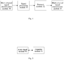
- the signal modulation and demodulation unit includes a multi-channel signal identification module, a signal processing module, a protocol module, and a multi-channel signal transmission module, which are connected successively.
- the multi-channel signal identification module simultaneously demodulates multi-channel ASK signals to realize the conversion from analog signal to digital signal.
- the signal processing module is responsible for the routing management of the communication of multiple electronic devices, and encodes and encapsulates the digital signals of the multi-channel signal identification module.
- the encapsulated signal is translated by the protocol module according to the QI standard or the PMA standard.
- the protocol module passes the translated signal to the control unit for processing, and the protocol module transmits the control command signal from the control unit to the multi-channel signal transmission module according to the QI standard or the PMA standard.
- the multi-channel signal transmission module simultaneously modulates the multi-channel signal according to the FSK mode and loads the modulated signal onto the specified coil of the coil module unit.
- the driving unit drives the coil module unit to work by using a half-bridge or a full-bridge method.
- the coil module unit includes an array signal antenna and a capacitor module which are connected to each other.
- the array signal antenna is composed of a plurality of sets of coils arranged according to the spatial distribution of the magnetic field; and the array signal antenna controls the operation of the corresponding single or multiple sets of array antennas through the control unit.
- the capacitor module is an integrated circuit composed of a plurality of capacitors; and the capacitor module changes the capacitance value according to the instruction of the control unit, so as to match the array signal antenna to generate different oscillation frequencies.
- the communication modes adopted by the communication unit include LIN, CAN, MOST, and Bluetooth.
- an array wireless antenna an electronic frequency modulation method, a multi-channel routing technology, and FSK and ASK modulation techniques are used to realize the functions of multi-device, multi-protocol charging, and charging the devices without alignment. Furthermore, a convolutional neural network algorithm and a fuzzy algorithm are used to solve the problems of intelligent charging management and efficient charging of the devices.
- 1-electric power supply unit 2-control unit, 3-signal modulation and demodulation unit, 4-driving unit, 5-coil module unit, 6-communication unit, 10-protection module, 11-power management module, 12-power output module, 20-learning module, 21-storage module, 22-control module, 30-multi-channel signal identification module, 31-signal processing module, 32-protocol module, 33-multi-channel signal transmission module, 50-array signal antenna, 51-capacitor module.
- the intelligent in-vehicle wireless charging device includes electric power supply unit 1, control unit 2, signal modulation and demodulation unit 3, driving unit 4, coil module unit 5, and communication unit 6.
- Control unit 2 is respectively connected to electric power supply unit 1, signal modulation and demodulation unit 3, driving unit 4, and communication unit 6.
- Driving unit 4 is connected to coil module unit 5.
- Coil module unit 5 is connected to signal modulation and demodulation unit 3.
- Electric power supply unit 1 supplies power to other units.
- Control unit 2 controls driving unit 4 to drive coil module unit 5 to generate oscillation.
- Signal modulation and demodulation unit 3 demodulates the information from the electronic devices and simultaneously modulates the information sent by control unit 2 onto coil module unit 5.
- Communication unit 6 interacts and share information with the vehicle body or periphery devices.
- electric power supply unit 1 is a component for supplying power to the entire wireless charging device.
- Electric power supply unit 1 includes protection module 10, power management module 11, and power output module 12 which are connected successively.
- Protection module 10 plays a role of isolation to protect the wireless charging device from the impact of the power supply of the vehicle and to prevent the failed wireless charging device from affecting the vehicle.
- Power management module 11 is configured for a conversion of a wide voltage from 5 V to 25 V, which allows a voltage input in a range from 5 V to 25 V.
- Power output module 12 provides operating voltage for the wireless charging device.
- control unit 2 is a processing system of the wireless charging device.
- Control unit 2 includes learning module 20, storage module 21, and control module 22 which are connected successively.
- Learning module 20 uses a convolutional neural network algorithm to record the ID numbers of various electronic devices, analyzes the battery status of the electronic devices, and stores data in storage module 21.
- Control module 22 extracts the data from storage module 21, and then performs BMS management for an electronic device ever recorded. Meanwhile, control module 22 optimizes the traditional PID algorithm by using a fuzzy algorithm, which can control the driving operation of driving unit 4 more efficiently and achieve higher power conversion efficiency.
- signal modulation and demodulation unit 3 is an interactive system of the wireless charging device and the electronic devices.
- Signal modulation and demodulation unit 3 includes multi-channel signal identification module 30, signal processing module 31, protocol module 32, and multi-channel signal transmission module 33 which are connected successively.
- Multi-channel signal identification module 30 demodulates multi-channel ASK signals simultaneously to realize the conversion from analog signal to digital signal.
- Signal processing module 31 is responsible for the routing management of the communication of multiple electronic devices, and encodes and encapsulates the digital signals of multi-channel signal identification module 30. The encapsulated signal is translated by protocol module 32 according to the QI standard or the PMA standard.
- Protocol module 32 passes the translated signal to control unit 2 for processing, and protocol module 32 transmits the control command signal from control unit 2 to multi-channel signal transmission module 33 according to the QI standard or the PMA standard.
- Multi-channel signal transmission module 33 simultaneously modulates the multi-channel signal according to the FSK mode and loads the modulated signal onto the specified coil of coil module unit 5.
- coil module unit 5 is the core part of the power transfer.
- Coil module unit 5 includes array signal antenna 50 and capacitor module 51 which are connected to each other.
- Array signal antenna 50 is composed of a plurality of sets of coils arranged according to the spatial distribution of the magnetic field; and array signal antenna 50 controls the operation of the corresponding single or multiple sets of array antennas through control unit 2. By doing so, multiple wireless charging devices are operated on the same platform, and each device can control the corresponding array antenna without interfering with others.
- Capacitor module 51 is an integrated circuit composed of a plurality of capacitors. Capacitor module 51 changes the capacitance value according to the instruction of control unit 2, so as to match array signal antenna 50 to generate different oscillation frequencies, thereby being compatible for the QI standard and the PMA standard.
Landscapes
- Engineering & Computer Science (AREA)
- Computer Networks & Wireless Communication (AREA)
- Power Engineering (AREA)
- Charge And Discharge Circuits For Batteries Or The Like (AREA)
- Near-Field Transmission Systems (AREA)
- Electric Propulsion And Braking For Vehicles (AREA)
Claims (6)
- Intelligente kabellose Ladevorrichtung im Fahrzeug, umfassend eine elektrische Stromversorgungseinheit (1), eine Steuereinheit (2), eine Signalmodulations- und Demodulationseinheit (3), eine Antriebseinheit (4), eine Spulenmoduleinheit (5) und eine Kommunikationseinheit (6); wobei die Steuereinheit (2) mit der elektrischen Stromversorgungseinheit (1) verbunden ist, die Steuereinheit (2) mit der Signalmodulations- und Demodulationseinheit (3) verbunden ist, die Steuereinheit (2) mit der Antriebseinheit (4) verbunden ist und die Steuereinheit (2) mit der Kommunikationseinheit (6) verbunden ist; die Antriebseinheit (4) mit der Spulenmoduleinheit (5) verbunden ist; die Spulenmoduleinheit (5) mit der Signalmodulations- und Demodulationseinheit (3) verbunden ist;
die elektrische Stromversorgungseinheit (1) ist angepasst, um andere Einheiten mit Strom zu versorgen; die Steuereinheit (2) ist angepasst, um die Antriebseinheit (4) zu steuern, um die Spulenmoduleinheit (5) anzutreiben, um eine Schwingung zu erzeugen; die Signalmodulations- und Demodulationseinheit (3) ist angepasst, um Informationen von elektronischen Geräten zu demodulieren und gleichzeitig Informationen zu modulieren, die von der Steuereinheit (2) an die Spulenmoduleinheit (5) gesendet werden; und die Kommunikationseinheit (6) ist angepasst, um Informationen mit Geräten zu interagieren und auszutauschen, die sich in einem Fahrzeug befinden oder durch die Signalmodulations- und Demodulationseinheit (3) vom Fahrzeug getrennt sind;
die Signalmodulations- und Demodulationseinheit (3) umfasst ein Mehrkanalsignalidentifikationsmodul (30), ein Signalverarbeitungsmodul (31), ein Protokollmodul (32) und ein Mehrkanalsignalübertragungsmodul (33); das Mehrkanalsignalidentifikationsmodul (30), das Signalverarbeitungsmodul (31), das Protokollmodul (32) und das Mehrkanalsignalübertragungsmodul (33) sind nacheinander verbunden; das Mehrkanalsignalidentifikationsmodul (30) ist angepasst, um mehrkanalige ASK-Signale gleichzeitig zu demodulieren, um eine Umwandlung von einem analogen Signal in ein digitales Signal zu realisieren; das Signalverarbeitungsmodul (31) ist angepasst, um für ein Routing-Management einer Kommunikation mehrerer elektronischer Geräte verantwortlich zu sein und digitale Signale des Mehrkanalsignalidentifikationsmoduls (30) zu kodieren und einzukapseln; ein eingekapseltes Signal wird von dem Protokollmodul (32) übersetzt, das entsprechend einem QI-Standard oder einem PMA-Standard angepasst ist; das Protokollmodul (32) ist angepasst, um ein übersetztes Signal an die Steuereinheit (2) zur Verarbeitung weiterzuleiten, um ein Steuerbefehlssignal von der Steuereinheit (2) an das Mehrkanalsignalübertragungsmodul (33) gemäß dem QI-Standard oder der PMA-Standard zu übertragen; das Mehrkanalsignalübertragungsmodul (33) ist angepasst, um das Mehrkanalsignal gleichzeitig gemäß einem FSK-Modus zu modulieren und um ein moduliertes Signal auf eine spezifizierte Spule der Spulenmoduleinheit (5) zu laden. - Intelligente kabellose Ladevorrichtung im Fahrzeug nach Anspruch 1, wobei die elektrische Stromversorgungseinheit (1) ein Schutzmodul (10), ein Energieverwaltungsmodul (11) und ein Leistungsausgangsmodul (12) umfasst; das Schutzmodul (10), das Energieverwaltungsmodul (11) und das Leistungsausgangsmodul (12) nacheinander verbunden sind; das Energieverwaltungsmodul (11) für eine Umwandlung einer breiten Spannung von 5 V bis 25 V konfiguriert ist; und das Leistungsausgangsmodul (12) angepasst ist, um Betriebsspannung für die drahtlose Ladevorrichtung bereitzustellen.
- Intelligente kabellose Ladevorrichtung im Fahrzeug nach Anspruch 1, wobei die Steuereinheit (2) ein Lernmodul (20), ein Speichermodul (21) und ein Steuermodul (22) umfasst; das Lernmodul (20), das Speichermodul (21) und das Steuermodul (22) nacheinander verbunden sind; das Lernmodul (20) angepasst ist, um einen Faltungsalgorithmus für ein neuronales Netzwerk zu verwenden, um ID-Nummern verschiedener elektronischer Geräte aufzuzeichnen, um den Batteriestatus der elektronischen Geräte zu analysieren und Daten in dem Speichermodul (21) zu speichern; das Steuermodul (22) angepasst ist, um die Daten aus dem Speichermodul (21) zu extrahieren und dann ein BMS-Management (Batteriemanagementsystem) für ein jemals aufgezeichnetes elektronisches Gerät durchzuführen; und einen Fuzzy-Algorithmus zu verwenden, um einen Fahrbetrieb der Antriebseinheit (4) zu steuern.
- Intelligente kabellose Ladevorrichtung im Fahrzeug nach Anspruch 1, wobei die Antriebseinheit (4) angepasst ist, um die Spulenmoduleinheit (5) anzutreiben, um unter Verwendung eines Halbbrücken- oder eines Vollbrückenverfahrens zu arbeiten.
- Intelligente kabellose Ladevorrichtung im Fahrzeug nach Anspruch 1, wobei die Spulenmoduleinheit (5) eine Array-Signalantenne (50) und ein Kondensatormodul (51) umfasst; die Array-Signalantenne (50) und das Kondensatormodul (51) miteinander verbunden sind; die Array-Signalantenne (50) mehrere Sätze von Spulen umfasst, die gemäß einer räumlichen Verteilung eines Magnetfelds angeordnet sind; und die Array-Signalantenne (50) angepasst ist, um einen Betrieb entsprechender einzelner oder mehrerer Sätze von Array-Antennen durch die Steuereinheit (2) zu steuern; das Kondensatormodul (51) eine integrierte Schaltung ist, die aus mehreren Kondensatoren besteht; und das Kondensatormodul (51) angepasst ist, um Kapazitätswerte gemäß einer Anweisung der Steuereinheit (2) zu ändern, um sie an die Array-Signalantenne (50) anzupassen, um unterschiedliche Schwingungsfrequenzen zu erzeugen.
- Intelligente kabellose Ladevorrichtung im Fahrzeug nach Anspruch 1, wobei ein von der Kommunikationseinheit (6) angenommener Kommunikationsmodus LIN, CAN, MOST und Bluetooth umfasst.
Applications Claiming Priority (2)
| Application Number | Priority Date | Filing Date | Title |
|---|---|---|---|
| CN201810319521.1A CN108711947B (zh) | 2018-04-11 | 2018-04-11 | 一种智能车载无线充电装置 |
| PCT/CN2018/110030 WO2019196367A1 (zh) | 2018-04-11 | 2018-10-12 | 一种智能车载无线充电装置 |
Publications (3)
| Publication Number | Publication Date |
|---|---|
| EP3579378A1 EP3579378A1 (de) | 2019-12-11 |
| EP3579378A4 EP3579378A4 (de) | 2020-01-15 |
| EP3579378B1 true EP3579378B1 (de) | 2020-08-19 |
Family
ID=63866585
Family Applications (1)
| Application Number | Title | Priority Date | Filing Date |
|---|---|---|---|
| EP18874982.4A Active EP3579378B1 (de) | 2018-04-11 | 2018-10-12 | Intelligente drahtlosladevorrichtung für fahrzeug |
Country Status (4)
| Country | Link |
|---|---|
| EP (1) | EP3579378B1 (de) |
| JP (1) | JP6878592B2 (de) |
| CN (1) | CN108711947B (de) |
| WO (1) | WO2019196367A1 (de) |
Families Citing this family (5)
| Publication number | Priority date | Publication date | Assignee | Title |
|---|---|---|---|---|
| CN111030260A (zh) * | 2020-01-06 | 2020-04-17 | 深圳市新世宇实业有限公司 | 一种车载充电装置和车辆 |
| CN112769173B (zh) * | 2020-12-24 | 2023-05-16 | 深圳劲芯微电子有限公司 | 一种双解码充电控制系统、控制方法及电子设备 |
| CN115800466A (zh) * | 2022-12-16 | 2023-03-14 | 苏州东灿光电科技有限公司 | 一种车载无线充电器电路 |
| CN116198348A (zh) * | 2023-05-06 | 2023-06-02 | 宁德时代新能源科技股份有限公司 | 无线供电系统和车辆 |
| CN120150379B (zh) * | 2025-03-11 | 2025-10-28 | 国网江苏省电力有限公司电力科学研究院 | 基于负载估算的模糊pid无线电能传输控制方法、系统和装置 |
Family Cites Families (14)
| Publication number | Priority date | Publication date | Assignee | Title |
|---|---|---|---|---|
| US8183827B2 (en) * | 2003-01-28 | 2012-05-22 | Hewlett-Packard Development Company, L.P. | Adaptive charger system and method |
| JP4587306B2 (ja) * | 2005-04-20 | 2010-11-24 | 株式会社デンソー | 二次電池の残存容量演算方法 |
| JP4725611B2 (ja) * | 2008-07-16 | 2011-07-13 | セイコーエプソン株式会社 | 送電制御装置、送電装置、受電制御装置、受電装置及び電子機器 |
| CA2757623A1 (en) * | 2009-04-08 | 2010-10-14 | Access Business Group International Llc | Selectable coil array |
| JP2011127973A (ja) * | 2009-12-16 | 2011-06-30 | Kawasaki Heavy Ind Ltd | 二次電池の充電状態推定方法及び装置 |
| CN102263441B (zh) * | 2010-05-27 | 2013-06-12 | 富达通科技股份有限公司 | 感应式电源供应器中数据传输的方法 |
| JP5539069B2 (ja) * | 2010-06-30 | 2014-07-02 | キヤノン株式会社 | 給電装置 |
| KR101739293B1 (ko) * | 2010-12-23 | 2017-05-24 | 삼성전자주식회사 | 인 밴드 통신을 이용한 무선 전력 송수신 시스템 |
| JP5273269B1 (ja) * | 2012-02-23 | 2013-08-28 | パナソニック株式会社 | 車載用充電装置とそれを搭載した自動車 |
| US9882427B2 (en) * | 2013-05-10 | 2018-01-30 | Energous Corporation | Wireless power delivery using a base station to control operations of a plurality of wireless power transmitters |
| US9608454B2 (en) * | 2012-12-03 | 2017-03-28 | WIPQTUS Inc. | Wireless power system with a self-regulating wireless power receiver |
| US20150303731A1 (en) * | 2012-12-28 | 2015-10-22 | Hitachi, Ltd. | Electric Energy Storage Device |
| WO2015140917A1 (ja) * | 2014-03-18 | 2015-09-24 | 三菱電機エンジニアリング株式会社 | 共振型電力伝送装置、送信側電力伝送装置及び受信側電力伝送装置 |
| CN208423944U (zh) * | 2018-04-11 | 2019-01-22 | 常州星宇车灯股份有限公司 | 一种智能车载无线充电装置 |
-
2018
- 2018-04-11 CN CN201810319521.1A patent/CN108711947B/zh active Active
- 2018-10-12 EP EP18874982.4A patent/EP3579378B1/de active Active
- 2018-10-12 WO PCT/CN2018/110030 patent/WO2019196367A1/zh not_active Ceased
- 2018-10-12 JP JP2019532719A patent/JP6878592B2/ja active Active
Non-Patent Citations (1)
| Title |
|---|
| None * |
Also Published As
| Publication number | Publication date |
|---|---|
| CN108711947A (zh) | 2018-10-26 |
| CN108711947B (zh) | 2020-03-13 |
| EP3579378A1 (de) | 2019-12-11 |
| JP2020520618A (ja) | 2020-07-09 |
| WO2019196367A1 (zh) | 2019-10-17 |
| JP6878592B2 (ja) | 2021-05-26 |
| EP3579378A4 (de) | 2020-01-15 |
Similar Documents
| Publication | Publication Date | Title |
|---|---|---|
| EP3579378B1 (de) | Intelligente drahtlosladevorrichtung für fahrzeug | |
| US9548796B2 (en) | Wireless power transceiver system | |
| US9368996B2 (en) | Wireless power and data transmission and reception system | |
| CN102801218B (zh) | 无线电能和数据传输系统 | |
| US10069344B2 (en) | Method and device for transmitting and receiving wireless power | |
| US20170271889A1 (en) | Power storage apparatus, electronic apparatus, electric vehicle, and electric power system | |
| CN106415981A (zh) | 包含可变电力/适应性负载调变的无线充电系统 | |
| CN104512271A (zh) | 电动汽车的蓄电器的充电 | |
| KR20120135873A (ko) | 무선 전력 전송 장치 및 시스템 | |
| KR20130125555A (ko) | 무선 전력 수신 장치 및 방법, 무선 전력 전송 장치 및 방법 | |
| CN203434667U (zh) | 一种无线充电rfid通信装置 | |
| US20210210989A1 (en) | Amplitude shift key modulation for multi-device wireless chargers | |
| CN101373928B (zh) | 一种用于汽车的电源转换器系统 | |
| US6292069B1 (en) | Loosely coupled rotary transformer having resonant circuit | |
| CN208369270U (zh) | 线圈模组充电电路、两组线圈模组充电电路和充电器 | |
| CN208423944U (zh) | 一种智能车载无线充电装置 | |
| CN103382945A (zh) | 一种风扇控制系统 | |
| KR102340149B1 (ko) | 통신 장치 및 이를 포함하는 통신 시스템 | |
| KR20240064259A (ko) | 최소 통신 채널을 갖는 배터리 관리 시스템 및 이의 운영 방법 | |
| CN107959353B (zh) | 一种无线充电装置及方法 | |
| CN103390923B (zh) | 利用电磁波对有源卡片进行充电的方法、装置和系统 | |
| US20250105672A1 (en) | Novel vehicle-mounted wireless charging system | |
| CN208623397U (zh) | 无线充电设备 | |
| KR20220109850A (ko) | 무선으로 전력을 송신하거나, 무선으로 전력을 수신하는 전자 장치 및 그 동작 방법 | |
| CN108599390A (zh) | 一种采用e类放大器实现原副边通信的无线电能传输系统 |
Legal Events
| Date | Code | Title | Description |
|---|---|---|---|
| STAA | Information on the status of an ep patent application or granted ep patent |
Free format text: STATUS: UNKNOWN |
|
| STAA | Information on the status of an ep patent application or granted ep patent |
Free format text: STATUS: THE INTERNATIONAL PUBLICATION HAS BEEN MADE |
|
| PUAI | Public reference made under article 153(3) epc to a published international application that has entered the european phase |
Free format text: ORIGINAL CODE: 0009012 |
|
| STAA | Information on the status of an ep patent application or granted ep patent |
Free format text: STATUS: REQUEST FOR EXAMINATION WAS MADE |
|
| 17P | Request for examination filed |
Effective date: 20190513 |
|
| AK | Designated contracting states |
Kind code of ref document: A1 Designated state(s): AL AT BE BG CH CY CZ DE DK EE ES FI FR GB GR HR HU IE IS IT LI LT LU LV MC MK MT NL NO PL PT RO RS SE SI SK SM TR |
|
| AX | Request for extension of the european patent |
Extension state: BA ME |
|
| A4 | Supplementary search report drawn up and despatched |
Effective date: 20191218 |
|
| RIC1 | Information provided on ipc code assigned before grant |
Ipc: H02J 50/10 20160101ALI20191212BHEP Ipc: H02J 7/02 20160101AFI20191212BHEP |
|
| REG | Reference to a national code |
Ref country code: DE Ref legal event code: R079 Ref document number: 602018007142 Country of ref document: DE Free format text: PREVIOUS MAIN CLASS: H02J0050120000 Ipc: H02J0007020000 |
|
| GRAP | Despatch of communication of intention to grant a patent |
Free format text: ORIGINAL CODE: EPIDOSNIGR1 |
|
| STAA | Information on the status of an ep patent application or granted ep patent |
Free format text: STATUS: GRANT OF PATENT IS INTENDED |
|
| RIC1 | Information provided on ipc code assigned before grant |
Ipc: H02J 7/02 20160101AFI20200513BHEP Ipc: H02J 50/10 20160101ALI20200513BHEP |
|
| INTG | Intention to grant announced |
Effective date: 20200615 |
|
| GRAS | Grant fee paid |
Free format text: ORIGINAL CODE: EPIDOSNIGR3 |
|
| GRAA | (expected) grant |
Free format text: ORIGINAL CODE: 0009210 |
|
| STAA | Information on the status of an ep patent application or granted ep patent |
Free format text: STATUS: THE PATENT HAS BEEN GRANTED |
|
| AK | Designated contracting states |
Kind code of ref document: B1 Designated state(s): AL AT BE BG CH CY CZ DE DK EE ES FI FR GB GR HR HU IE IS IT LI LT LU LV MC MK MT NL NO PL PT RO RS SE SI SK SM TR |
|
| DAV | Request for validation of the european patent (deleted) | ||
| DAX | Request for extension of the european patent (deleted) | ||
| REG | Reference to a national code |
Ref country code: CH Ref legal event code: EP |
|
| REG | Reference to a national code |
Ref country code: DE Ref legal event code: R096 Ref document number: 602018007142 Country of ref document: DE |
|
| REG | Reference to a national code |
Ref country code: AT Ref legal event code: REF Ref document number: 1305065 Country of ref document: AT Kind code of ref document: T Effective date: 20200915 |
|
| REG | Reference to a national code |
Ref country code: IE Ref legal event code: FG4D |
|
| REG | Reference to a national code |
Ref country code: LT Ref legal event code: MG4D |
|
| REG | Reference to a national code |
Ref country code: NL Ref legal event code: MP Effective date: 20200819 |
|
| PG25 | Lapsed in a contracting state [announced via postgrant information from national office to epo] |
Ref country code: SE Free format text: LAPSE BECAUSE OF FAILURE TO SUBMIT A TRANSLATION OF THE DESCRIPTION OR TO PAY THE FEE WITHIN THE PRESCRIBED TIME-LIMIT Effective date: 20200819 Ref country code: BG Free format text: LAPSE BECAUSE OF FAILURE TO SUBMIT A TRANSLATION OF THE DESCRIPTION OR TO PAY THE FEE WITHIN THE PRESCRIBED TIME-LIMIT Effective date: 20201119 Ref country code: LT Free format text: LAPSE BECAUSE OF FAILURE TO SUBMIT A TRANSLATION OF THE DESCRIPTION OR TO PAY THE FEE WITHIN THE PRESCRIBED TIME-LIMIT Effective date: 20200819 Ref country code: NO Free format text: LAPSE BECAUSE OF FAILURE TO SUBMIT A TRANSLATION OF THE DESCRIPTION OR TO PAY THE FEE WITHIN THE PRESCRIBED TIME-LIMIT Effective date: 20201119 Ref country code: PT Free format text: LAPSE BECAUSE OF FAILURE TO SUBMIT A TRANSLATION OF THE DESCRIPTION OR TO PAY THE FEE WITHIN THE PRESCRIBED TIME-LIMIT Effective date: 20201221 Ref country code: GR Free format text: LAPSE BECAUSE OF FAILURE TO SUBMIT A TRANSLATION OF THE DESCRIPTION OR TO PAY THE FEE WITHIN THE PRESCRIBED TIME-LIMIT Effective date: 20201120 Ref country code: FI Free format text: LAPSE BECAUSE OF FAILURE TO SUBMIT A TRANSLATION OF THE DESCRIPTION OR TO PAY THE FEE WITHIN THE PRESCRIBED TIME-LIMIT Effective date: 20200819 Ref country code: HR Free format text: LAPSE BECAUSE OF FAILURE TO SUBMIT A TRANSLATION OF THE DESCRIPTION OR TO PAY THE FEE WITHIN THE PRESCRIBED TIME-LIMIT Effective date: 20200819 |
|
| REG | Reference to a national code |
Ref country code: AT Ref legal event code: MK05 Ref document number: 1305065 Country of ref document: AT Kind code of ref document: T Effective date: 20200819 |
|
| PG25 | Lapsed in a contracting state [announced via postgrant information from national office to epo] |
Ref country code: LV Free format text: LAPSE BECAUSE OF FAILURE TO SUBMIT A TRANSLATION OF THE DESCRIPTION OR TO PAY THE FEE WITHIN THE PRESCRIBED TIME-LIMIT Effective date: 20200819 Ref country code: PL Free format text: LAPSE BECAUSE OF FAILURE TO SUBMIT A TRANSLATION OF THE DESCRIPTION OR TO PAY THE FEE WITHIN THE PRESCRIBED TIME-LIMIT Effective date: 20200819 Ref country code: RS Free format text: LAPSE BECAUSE OF FAILURE TO SUBMIT A TRANSLATION OF THE DESCRIPTION OR TO PAY THE FEE WITHIN THE PRESCRIBED TIME-LIMIT Effective date: 20200819 Ref country code: NL Free format text: LAPSE BECAUSE OF FAILURE TO SUBMIT A TRANSLATION OF THE DESCRIPTION OR TO PAY THE FEE WITHIN THE PRESCRIBED TIME-LIMIT Effective date: 20200819 Ref country code: IS Free format text: LAPSE BECAUSE OF FAILURE TO SUBMIT A TRANSLATION OF THE DESCRIPTION OR TO PAY THE FEE WITHIN THE PRESCRIBED TIME-LIMIT Effective date: 20201219 |
|
| PG25 | Lapsed in a contracting state [announced via postgrant information from national office to epo] |
Ref country code: EE Free format text: LAPSE BECAUSE OF FAILURE TO SUBMIT A TRANSLATION OF THE DESCRIPTION OR TO PAY THE FEE WITHIN THE PRESCRIBED TIME-LIMIT Effective date: 20200819 Ref country code: RO Free format text: LAPSE BECAUSE OF FAILURE TO SUBMIT A TRANSLATION OF THE DESCRIPTION OR TO PAY THE FEE WITHIN THE PRESCRIBED TIME-LIMIT Effective date: 20200819 Ref country code: CZ Free format text: LAPSE BECAUSE OF FAILURE TO SUBMIT A TRANSLATION OF THE DESCRIPTION OR TO PAY THE FEE WITHIN THE PRESCRIBED TIME-LIMIT Effective date: 20200819 Ref country code: DK Free format text: LAPSE BECAUSE OF FAILURE TO SUBMIT A TRANSLATION OF THE DESCRIPTION OR TO PAY THE FEE WITHIN THE PRESCRIBED TIME-LIMIT Effective date: 20200819 Ref country code: SM Free format text: LAPSE BECAUSE OF FAILURE TO SUBMIT A TRANSLATION OF THE DESCRIPTION OR TO PAY THE FEE WITHIN THE PRESCRIBED TIME-LIMIT Effective date: 20200819 |
|
| REG | Reference to a national code |
Ref country code: DE Ref legal event code: R097 Ref document number: 602018007142 Country of ref document: DE |
|
| PG25 | Lapsed in a contracting state [announced via postgrant information from national office to epo] |
Ref country code: ES Free format text: LAPSE BECAUSE OF FAILURE TO SUBMIT A TRANSLATION OF THE DESCRIPTION OR TO PAY THE FEE WITHIN THE PRESCRIBED TIME-LIMIT Effective date: 20200819 Ref country code: AT Free format text: LAPSE BECAUSE OF FAILURE TO SUBMIT A TRANSLATION OF THE DESCRIPTION OR TO PAY THE FEE WITHIN THE PRESCRIBED TIME-LIMIT Effective date: 20200819 Ref country code: AL Free format text: LAPSE BECAUSE OF FAILURE TO SUBMIT A TRANSLATION OF THE DESCRIPTION OR TO PAY THE FEE WITHIN THE PRESCRIBED TIME-LIMIT Effective date: 20200819 |
|
| PLBE | No opposition filed within time limit |
Free format text: ORIGINAL CODE: 0009261 |
|
| STAA | Information on the status of an ep patent application or granted ep patent |
Free format text: STATUS: NO OPPOSITION FILED WITHIN TIME LIMIT |
|
| PG25 | Lapsed in a contracting state [announced via postgrant information from national office to epo] |
Ref country code: MC Free format text: LAPSE BECAUSE OF FAILURE TO SUBMIT A TRANSLATION OF THE DESCRIPTION OR TO PAY THE FEE WITHIN THE PRESCRIBED TIME-LIMIT Effective date: 20200819 Ref country code: SK Free format text: LAPSE BECAUSE OF FAILURE TO SUBMIT A TRANSLATION OF THE DESCRIPTION OR TO PAY THE FEE WITHIN THE PRESCRIBED TIME-LIMIT Effective date: 20200819 Ref country code: LU Free format text: LAPSE BECAUSE OF NON-PAYMENT OF DUE FEES Effective date: 20201012 |
|
| REG | Reference to a national code |
Ref country code: BE Ref legal event code: MM Effective date: 20201031 |
|
| 26N | No opposition filed |
Effective date: 20210520 |
|
| PG25 | Lapsed in a contracting state [announced via postgrant information from national office to epo] |
Ref country code: IT Free format text: LAPSE BECAUSE OF FAILURE TO SUBMIT A TRANSLATION OF THE DESCRIPTION OR TO PAY THE FEE WITHIN THE PRESCRIBED TIME-LIMIT Effective date: 20200819 |
|
| PG25 | Lapsed in a contracting state [announced via postgrant information from national office to epo] |
Ref country code: BE Free format text: LAPSE BECAUSE OF NON-PAYMENT OF DUE FEES Effective date: 20201031 |
|
| PG25 | Lapsed in a contracting state [announced via postgrant information from national office to epo] |
Ref country code: IE Free format text: LAPSE BECAUSE OF NON-PAYMENT OF DUE FEES Effective date: 20201012 |
|
| PG25 | Lapsed in a contracting state [announced via postgrant information from national office to epo] |
Ref country code: TR Free format text: LAPSE BECAUSE OF FAILURE TO SUBMIT A TRANSLATION OF THE DESCRIPTION OR TO PAY THE FEE WITHIN THE PRESCRIBED TIME-LIMIT Effective date: 20200819 Ref country code: MT Free format text: LAPSE BECAUSE OF FAILURE TO SUBMIT A TRANSLATION OF THE DESCRIPTION OR TO PAY THE FEE WITHIN THE PRESCRIBED TIME-LIMIT Effective date: 20200819 Ref country code: CY Free format text: LAPSE BECAUSE OF FAILURE TO SUBMIT A TRANSLATION OF THE DESCRIPTION OR TO PAY THE FEE WITHIN THE PRESCRIBED TIME-LIMIT Effective date: 20200819 |
|
| REG | Reference to a national code |
Ref country code: CH Ref legal event code: PL |
|
| PG25 | Lapsed in a contracting state [announced via postgrant information from national office to epo] |
Ref country code: MK Free format text: LAPSE BECAUSE OF FAILURE TO SUBMIT A TRANSLATION OF THE DESCRIPTION OR TO PAY THE FEE WITHIN THE PRESCRIBED TIME-LIMIT Effective date: 20200819 |
|
| PG25 | Lapsed in a contracting state [announced via postgrant information from national office to epo] |
Ref country code: LI Free format text: LAPSE BECAUSE OF NON-PAYMENT OF DUE FEES Effective date: 20211031 Ref country code: CH Free format text: LAPSE BECAUSE OF NON-PAYMENT OF DUE FEES Effective date: 20211031 |
|
| PG25 | Lapsed in a contracting state [announced via postgrant information from national office to epo] |
Ref country code: SI Free format text: LAPSE BECAUSE OF FAILURE TO SUBMIT A TRANSLATION OF THE DESCRIPTION OR TO PAY THE FEE WITHIN THE PRESCRIBED TIME-LIMIT Effective date: 20200819 |
|
| PGFP | Annual fee paid to national office [announced via postgrant information from national office to epo] |
Ref country code: GB Payment date: 20250813 Year of fee payment: 8 |
|
| PGFP | Annual fee paid to national office [announced via postgrant information from national office to epo] |
Ref country code: FR Payment date: 20250813 Year of fee payment: 8 |
|
| PGFP | Annual fee paid to national office [announced via postgrant information from national office to epo] |
Ref country code: DE Payment date: 20250826 Year of fee payment: 8 |