EP3578710A2 - Verfahren und vorrichtung zur kontinuierlichen erfassung und zum schneiden von gewebe für kleidungstücke - Google Patents
Verfahren und vorrichtung zur kontinuierlichen erfassung und zum schneiden von gewebe für kleidungstücke Download PDFInfo
- Publication number
- EP3578710A2 EP3578710A2 EP19178101.2A EP19178101A EP3578710A2 EP 3578710 A2 EP3578710 A2 EP 3578710A2 EP 19178101 A EP19178101 A EP 19178101A EP 3578710 A2 EP3578710 A2 EP 3578710A2
- Authority
- EP
- European Patent Office
- Prior art keywords
- points
- fabric
- tes
- cutting
- theoretical
- Prior art date
- Legal status (The legal status is an assumption and is not a legal conclusion. Google has not performed a legal analysis and makes no representation as to the accuracy of the status listed.)
- Granted
Links
Images


Classifications
-
- D—TEXTILES; PAPER
- D06—TREATMENT OF TEXTILES OR THE LIKE; LAUNDERING; FLEXIBLE MATERIALS NOT OTHERWISE PROVIDED FOR
- D06H—MARKING, INSPECTING, SEAMING OR SEVERING TEXTILE MATERIALS
- D06H7/00—Apparatus or processes for cutting, or otherwise severing, specially adapted for the cutting, or otherwise severing, of textile materials
- D06H7/24—Devices specially adapted for cutting-out samples
-
- B—PERFORMING OPERATIONS; TRANSPORTING
- B26—HAND CUTTING TOOLS; CUTTING; SEVERING
- B26D—CUTTING; DETAILS COMMON TO MACHINES FOR PERFORATING, PUNCHING, CUTTING-OUT, STAMPING-OUT OR SEVERING
- B26D5/00—Arrangements for operating and controlling machines or devices for cutting, cutting-out, stamping-out, punching, perforating, or severing by means other than cutting
- B26D5/007—Control means comprising cameras, vision or image processing systems
-
- B—PERFORMING OPERATIONS; TRANSPORTING
- B26—HAND CUTTING TOOLS; CUTTING; SEVERING
- B26F—PERFORATING; PUNCHING; CUTTING-OUT; STAMPING-OUT; SEVERING BY MEANS OTHER THAN CUTTING
- B26F1/00—Perforating; Punching; Cutting-out; Stamping-out; Apparatus therefor
- B26F1/38—Cutting-out; Stamping-out
- B26F1/3806—Cutting-out; Stamping-out wherein relative movements of tool head and work during cutting have a component tangential to the work surface
- B26F1/3813—Cutting-out; Stamping-out wherein relative movements of tool head and work during cutting have a component tangential to the work surface wherein the tool head is moved in a plane parallel to the work in a coordinate system fixed with respect to the work
-
- B—PERFORMING OPERATIONS; TRANSPORTING
- B26—HAND CUTTING TOOLS; CUTTING; SEVERING
- B26D—CUTTING; DETAILS COMMON TO MACHINES FOR PERFORATING, PUNCHING, CUTTING-OUT, STAMPING-OUT OR SEVERING
- B26D5/00—Arrangements for operating and controlling machines or devices for cutting, cutting-out, stamping-out, punching, perforating, or severing by means other than cutting
- B26D2005/002—Performing a pattern matching operation
Definitions
- the invention relates to the field of preparation of items of clothing, in particular made with fabrics with striped and/or checked patterns.
- the invention relates to an apparatus/method for continuous detection and cutting of fabrics bearing striped and/or checked patterns for making items of clothing and the following description refers to this field of application to simplify its presentation.
- the fabric input into the cutting area is photographed by a camera mounted on a cutting head; the camera takes a series of photos of sample parts of the fabric, so as to photograph a sample of the pattern shown on the same.
- the camera Once the camera has taken the photos, it makes them available to an operator who, after viewing them, uses a mouse to select the points of the photographed pattern corresponding to the points of a predefined target model of an item of clothing to make.
- a general object of the present invention is to overcome the drawbacks of the known art.
- a specific object of the invention is to provide a continuous detection and cutting system of fabric for items of clothing and a corresponding detection and cutting method that is optimised in terms of execution efficiency.
- a further object of the present invention is to provide a continuous detection and cutting system of fabric for items of clothing and a corresponding detection and cutting method that minimises the execution time.
- Another object of the present invention is to provide a continuous detection and cutting system for items of clothing and a corresponding method for the detection and cutting of fabric that allow a precise alignment of stripes/checks between different component parts of the item of clothing to be made.
- the invention describes an apparatus for the continuous detection and cutting of fabric, bearing a predefined real striped and/or checked pattern, for making items of clothing, comprising:
- the processing unit is configured to perform said comparison by points between said theoretical points and said effective points according to the following steps:
- said theoretical points contain information representative of one or more from:
- said cutting head is configured to cut a first fabric in said cutting area simultaneously with one or more of the following operations:
- said processing unit is configured to process said effective and/or theoretical points while said fabric is transported from said loading area to said cutting area.
- said processing unit is further configured to process said defect points.
- the apparatus comprises a two-dimensional guide that supports said cutting head, and is arranged to make said cutting head translate in said cutting area along two directions perpendicular to each other.
- the first direction is parallel to the advancement direction, while the second direction is perpendicular to the advancement direction
- said processing unit is configured to transmit said real meeting points to said two-dimensional guide so that said two-dimensional guide guides said cutting head to cut said fabric in said cutting area according to said real meeting points.
- said processing unit is configured to set the detection of said effective points and/or of said defect indicators according to:
- said processing unit is configured to detect a new effective pitch by detecting subsequent measurements of the effective pitch and changing the effective pitch with the new pitch value, when the new pitch value is repeated a predefined number of times.
- the invention describes a method, actuated through a computer, for the continuous detection and cutting of fabric, bearing a predefined real striped and/or checked pattern, for making items of clothing, comprising the steps of:
- the cutting step is configured to cut, in said cutting area, a first fabric simultaneously with one or more of the following operations: processing, by said processing unit, effective and/or theoretical points of a second fabric arranged subsequently to the first;
- a step is provided for arranging a two-dimensional guide that supports said cutting head, and is arranged to make said cutting head translate in said cutting area along two directions perpendicular to each other.
- steps are provided for transmitting said real meeting points to said two-dimensional guide so that said two-dimensional guide guides said cutting head to cut said fabric in said cutting area according to said real meeting points.
- a step is provided for setting a detection of said effective points and/or of said defect indicators according to:
- a step is provided for detecting a new effective pitch by detecting subsequent measurements of the effective pitch and changing the effective pitch with the new pitch value, when the new pitch value is repeated a predefined number of times.
- the invention describes a computer program configured to perform the steps of the method of the second aspect of the invention.
- the invention describes a graphical user interface configured to display on a display device one or more of the steps performed by the method of the second aspect and/or by the computer program of the third aspect.
- the proposed solution of the invention provides for an automatic continuous detection of fabric and striped and/or checked patterns reproduced on the same, while, simultaneously, the processing takes place of information obtained from a previously detected fabric and/or, simultaneously, in a cutting area the cutting takes place of a previously detected and processed fabric.
- the different component parts made are prepared in conformity with a target model so that their composition determines an item of clothing with a precise alignment between stripes and checks.
- the invention describes an apparatus arranged for the detection and cutting of pieces of fabric needed to make an item of clothing from a predefined target model.
- pattern shall be intended as a striped and/or checked pattern, according to the present invention.
- the apparatus 1 for the continuous cutting comprises a loading area A1, a cutting area A2, and an unloading area A3.
- the loading area A1 is arranged for loading the fabric Tes_i so that it is detected.
- the fabric Tes_i bears the theoretical pattern Tex_i established on the basis of a target model Mod_T_i.
- the fabric tes_i is moved through the apparatus 1 in an advancement direction Dir away from the loading area A1.
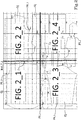
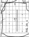
- the fabric tes_i is cut on the basis of the predefined target model Mod_T_i ( fig.2 and fig. 2A ), made according to specific criteria.
- an item of clothing C1 can be composed of component parts C11, C12, C13, etc. and made with the fabric Tes_1 on the basis of a target model Mod_T_1.
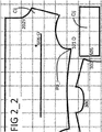
- the theoretical points P0_i are in reference to the cutting area A2; in particular, the positioning of the theoretical points P0_i is in reference to a theoretical grid GTiXY, at least partially relative to the cutting area A2; the target model Mod_T_i and the corresponding theoretical reference grid GTiXY are shown in figure 2 and 2A .
- the height of the theoretical grid GTiXY is limited by the height of the cutting area, i.e. by the dimension of the cutting area along a direction perpendicular to an advancement direction Dir, while the length of the theoretical grid, i.e. the dimension of the theoretical grid along a direction parallel to the advancement direction Dir, can be greater than the corresponding dimension of the cutting area, limited only by the maximum scan length.
- the theoretical grid GTiXY is configured to define a first theoretical positioning (with a pitch P0XY very similar to the real pitch) of the component pieces of the clothing to make.
- two theoretical grids are also provided and, more generally, a plurality of theoretical grids, according to a possible combination of patterns to be represented.
- the theoretical points P0_i are representative of theoretical meeting points between the component parts Cij of the item of clothing Ci.
- the size of the frame of the theoretical grid GTiXY is called the pitch P0XY of the theoretical model Mod_T_i.
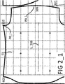
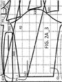
- a theoretical point P0_i can give the spatial relationship with the fabric, i.e. for example it can be representative of an alignment with a horizontal/vertical stripe of the fabric, in order to, for example, have the component part comprising the point have a stripe in a predefined position, such as in the centre.
- a theoretical point P0_i corresponds, for example at point 106 which is a reference point that has a relationship with the fabric, in particular with the line L_106 that indicates, for example, a centre line of a component part Cij of the item of clothing Ci.
- the items of information INFk comprise a cross-reference INF2 of a component part Cij with another component part Cij in the cutting area A2.
- the theoretical point P0_i corresponds, for example, to points 102 and 101O.
- the points 102, 101O are a pair of points in which the point 102 transfers a rule to the point 101O, for example a predefined distance from one horizontal line of a corresponding component part.
- the relationships are graphically shown between different theoretical points P0_i; for example, a first relation segment R1 identifies the relationship between the pair of points 102 and 101O, while a second relation segment R2 identifies the relationship between another pair of points 602 and 604.
- a point in a first component part which has a precise relationship with the theoretical pattern Tex_i can transfer its relationship to a second component part, through another point in the second component part; for example, points on two homologous sleeves of an item of clothing can move the "relationships" with respect to the theoretical pattern Tex_i to a component part representing the central part of an item of clothing.
- the component part in figure 2 and 2A which comprises the line L_106 is the back of a shirt.
- a point on a component part Cij can transfer a rule of composition of the item of clothing Ci to another component part Cij, determining a "strategy" of the composition of the item of clothing Ci starting from the component parts Cij.
- the two items of information INF1,INF2 therefore define a rule of composition of the item of clothing Ci to be made with the component parts Cij.
- the theoretical points P0_i are points that guide the alignment of the component parts Cij in order to determine an exact composition of the item of clothing Ci and an exact continuity of the theoretical pattern Tex_i in the entire item of clothing Ci.
- the rules INFk ensure that there is continuity in the pattern of the theoretical model, which must be transmitted to the effective pattern detected on the real fabric Tes_i.
- a further technical effect achieved by the application of the theoretical model on the real fabric, according to the invention, is also the reproduction of the theoretical pattern with an exact continuity on the real fabric.
- the theoretical points P0_i as represented in figure 2 are arranged by a suitable automatic positioning program that, starting from an item of clothing provided with a theoretical pattern to be made, provides
- Tes_i Alternatively, a single fabric Tes_i can be used for the interaction with the apparatus 1.
- the apparatus 1 for the continuous cutting comprises a loading area A1, a cutting area A2, and an unloading area A3.
- the loading area A1 is arranged for loading the fabric Tes_i so that it is detected.
- Appropriate loading means 60 are arranged to load the fabric Tes_i in the loading area A1; preferably, the loading means 60 comprises a fabric spreader roll.
- the continuous cutting apparatus 1 comprises an apparatus 80 for changing fabrics.
- the apparatus 80 for changing fabrics is arranged to remove an empty roll, i.e. a roll from which the fabric has already been unloaded towards the loading means 60, and to load a new roll so that there is no interruption in the continuous detection and cutting cycle.
- the technical effect obtained is the continuous operation of the apparatus 1 even in the case in which, at a given instant, a loaded roll of fabric is finished and it is necessary to load a subsequent roll.
- the apparatus 1 comprises a movement means 10 arranged for moving the fabric tes_i.
- the movement means 10 is arranged to move the fabric tes_i away from the loading area A1 in an advancement direction Dir, towards the cutting area A2, arranged downstream of the loading area A1.
- the movement means 10 comprises a conveyor belt.
- the set of effective points P1_i determines an effective grid GRiXY of the fabric tes_i detected.
- the detection means 20 has the purpose of detecting the real positioning of the fabric Tes_i in the loading area A1.
- the detection means 20 is arranged in the loading area A1.
- the detection means 20 is fixed in the advancement direction DIR and possibly movable in a direction transverse to the advancement direction.
- the detection means 20 is arranged at the inlet to the loading area A1 so that the detection of the fabric Tes_i at the inlet and the positioning of the fabric takes place without delay, so as to make the apparatus of the invention as efficient as possible.
- the detection means 20 comprises a scanner.
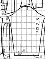
- both the theoretical grid GTiXY and the effective grid GRiXY are shown; the theoretical grid GTiXY is represented with dashed lines, while the effective grid GRiXY is represented with continuous lines; as can easily be seen, the two grids are slightly offset, as stated above.
- the real positioning of the fabric and of the real pattern TexR_i in reference to the theoretical grid GTiXY is detected by the detection means 20 and constitutes an input for a subsequent processing that precedes the step of cutting the fabric in the component parts Cij of the item of clothing Ci.
- the detection means 20 is further arranged to detect on the fabric Tes_i defect indicators D1_id,D2_id representative of non-conforming areas of fabric, hence determining corresponding defect points D1xy,D2xy.
- This detection is also carried out at the inlet to the loading area A1 so as to make the operation of the apparatus of the invention as efficient as possible.
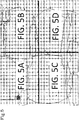
- the defect indicators D1_id ( fig. 8 ) comprise round defect stamps that indicate a single defect, such as, for example, a run/breakage in the fabric or an area stained during dyeing.
- the defect indicators D2_id comprise square defect stamps that indicate the beginning and end of a defective line, i.e. of a line with damaged fabric or fabric with an irregular pattern.
- the apparatus 1 of the invention comprises a device for off-line viewing 90.
- This device is arranged to parametrize the fabrics Tes_i before the continuous cutting.
- the device performs the parametrization only once for each piece of fabric, generating parameters P_check_i representative of the characteristics of the fabric (useful height of the fabric, pitch in the direction X, pitch in the direction Y, the gain of the camera that takes a photo of the fabric and the exposure of the camera that takes the photo of the fabric, markers, etc.).
- the technical effect ensured by the off-line viewing device 90 is a parametrization of the fabric Tes_i before the start of the cutting in order to then ensure the continuous cutting.
- the off-line detection of the fabric allows saving the information on the fabric Tes_i once in a database DB_check, associating it to an identifier ID_Tes_i of the controlled fabric, and thereby ensures that the fabric can be cut continuously without there being a further need to detect this information.
- the off-line viewing device 9 is installed on an external apparatus for quality control.
- the off-line viewing device 90 is coupled to the detection means 20 and the parameters P_check_i representative of the fabrics will be detected directly on the apparatus of the invention, before the beginning of the cutting operations, to take advantage of these parameters in the next cutting operation.
- the detection means 20 is arranged to receive the fabric control parameters P_check with the identifier ID_Tes_i from the off-line viewing device 90.
- the technical effect achieved is a further speeding up of the loading process of the fabric at the inlet, which further contributes to the continuous operation of the apparatus.
- the apparatus 1 for continuous cutting comprises a cutting head 30 ( fig.1A and 1B ).
- the apparatus 1 comprises a two-dimensional continuous cutting guide 50 ( fig.1A and 1B ) that supports said cutting head 30.
- the two-dimensional guide 50 is arranged to translate the cutting head 30 in the cutting area A2 along two directions Dir_X, Dir_Y perpendicular to each other.
- the first direction Dir_X is parallel to the advancement direction Dir
- the second direction Dir_Y is perpendicular to the advancement direction Dir.
- the apparatus 1 for continuous cutting further comprises a processing unit 40 ( fig. 1A and 1B ) configured to process the effective points P1_i detected and/or theoretical points P0_i established by the target model Mod_T_i.
- the processing unit 40 is logically divided into distinct functional modules (storage modules or operating modules) that perform the described functions.
- This processing unit 40 can comprise a single electronic device, appropriately programmed to perform the functionalities described, and the different modules can correspond to hardware entities and/or software routines that are part of the programmed device.
- these functions can be performed by a plurality of electronic devices on which the aforesaid functional modules can be distributed.
- the processing unit 40 can also make use of one or more processors for executing the instructions contained in the storage modules.
- the theoretical points P0_i are in reference to a theoretical grid GTiXY, while the effective points P1_i are in reference to an effective grid GRiXY.
- the processing of the invention provides for reproducing on the effective grid the positioning of the theoretical points with respect to the theoretical grid.
- the technical effect achieved is an adaptation of the theoretical model to the characteristics of the actual fabric detected.
- Another technical effect is that the cutting of the component parts Cij takes place in conformity with the real fabric tes_i received, i.e. on the effective characteristics of the fabric made starting from the theoretical Target model.
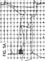
- Figure 5 shows a detail of figure 4 in which the points 106 and 107 are adapted with a shift from the centre of the respective numbered crosses (theoretical points) towards the left in the centre of the other crosses shown (effective points).
- the processing unit (40) is further configured to process the defect points D1xy,D2xy.
- the processing unit 40 is configured to process the defect points D1xy,D2xy through the steps of:
- the processing unit (40) is configured to process the effective points P1_i and/or theoretical points P0_i and/or defect points D1xy,D2xy while the fabric Tes_i is transported from the loading area A1 to the cutting area A2.
- Figure 8A shows the reference parameters of the operations shown in figure 8 .
- Figure 7A shows the reference parameters of the operations shown in figure 7 .
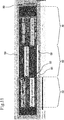
- Figure 11 shows together, and operatively simultaneously, the scanning, processing and cutting operations on different fabrics loaded in succession in the apparatus of the invention.
- the cutting head 30 is configured to cut the fabric Tes_i in the cutting area A2 according to the real meeting points PR_i determined.
- the technical effect obtained is an exact continuity of the pattern, also with fabric loaded crooked or warped or with a defective or irregular pattern.
- the meeting points PR_i were obtained through a detailed comparison between theoretical and effective points and possibly through comparison by defects.
- the detection means 20 is arranged to detect the effective points P1_i and/or the defect indicators D1_id,D2_id on the fabric tes_i arranged in the loading area A1.
- the fabric Tes_i will have a real pattern TexR_i equal to that of the target model Mod_T_i, but it can have a different effective pitch PRxy.
- the effective detection pitch PRxy is pre-set starting from the frequency of the stripe or check on the fabric Tes_i to detect.
- the pitch is the distance between two equal, immediately successive design parts in the real pattern of the fabric tes_i.
- the real pattern TexR_i is equal to that of the target model Mod_T_i, the distances between the stripes/checks can be different from those of the Target model Mod_T_i.
- the target model can be used for different items of clothing Ci with the same real pattern TexR_i, but with a different pitch Pxy, since, regardless of the pitch of the fabric, the meeting points of the model still remain the same because they ensure the continuity of the pattern on each fabric.
- the processing unit 40 is configured to set the detection of the effective points P1_i and/or the defect indicators D1_id,D2_id according to:
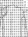
- a real pattern of the fabric tes_i detected by the detection means 20 is shown, in which the markers that identify the checks are centred on the intersections between the lines of the checks; in this case, therefore, the effective pitch PRxy is substantially regular, that is, the distances x and y from the centre of the marker at the ends of the check along the x and y axes are constant.
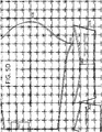
- a fabric tes_i can be loaded in the loading area having a different effective pitch PRxy due to imperfections in the fabric and/or in the positioning; an example is shown in figure 10 .
- the detection means 20 detects a different effective detection pitch PRxy, since the markers are no longer centred in the checks of the real pattern and the distances x and y vary accordingly, resulting irregular.
- the processing unit 40 is configured to detect a new effective pitch PRxy by detecting subsequent measurements of the effective pitch PRxy and changing the effective pitch with the new pitch value, when the new pitch value is repeated a predefined number of times, for example 2.
- the apparatus adapts to the variable pitch of the fabric tes_i due to various causes, such as irregular printing of the pattern, and/or effective positioning the fabric.
- the technical effect achieved is greater efficiency in the preparation of the component parts Cij that will be cut in the cutting step, thanks to the "refinement” of the effective pitch of the pattern actually present on the fabric tes_i to be cut.
- a console 70 is optionally provided ( fig. 1A ) which controls an additional precise pointing.
- the cutting head 30 is coupled to a camera that covers the cutting area A2 and the fabric tes_i in the cutting area.
- the detection of the fabric tes_i since the detection of the fabric tes_i takes place in the loading area A1 and the cutting area can be several metres away, it may occur that the fabric tes_i moves slightly with respect to the position detected by the detection means.
- the console allows performing a precise pointing, allowing the operator to define the exact position of an effective point P1_i on the fabric and make the appropriate adjustments in the position of the component pieces Cij.
- the method comprises the step of arranging a fabric (tes_i).
- the fabric tes_i will be moved from a loading area A1 to a cutting area A2 in an advancement direction Dir.
- the step of processing said effective P1_i and/or theoretical points P0_i is performed while said fabric (tes_i) is transported from a loading area A1 to a cutting area A2.
- the invention further provides a computer program configured to perform one or more of the steps of the method described.
- the invention described provides for an automatic continuous detection of fabric and the patterns reproduced on the same, while, simultaneously, the processing takes place of the information obtained from a previously detected fabric and/or, simultaneously, in a cutting area the cutting takes place of a previously detected fabric.
- the different component parts made are prepared in conformity with a target model so that their composition determines an item of clothing with a precise alignment between stripes and checks.
Landscapes
- Engineering & Computer Science (AREA)
- Life Sciences & Earth Sciences (AREA)
- Forests & Forestry (AREA)
- Mechanical Engineering (AREA)
- Computer Vision & Pattern Recognition (AREA)
- Textile Engineering (AREA)
- Treatment Of Fiber Materials (AREA)
- Control Of Cutting Processes (AREA)
Applications Claiming Priority (1)
| Application Number | Priority Date | Filing Date | Title |
|---|---|---|---|
| IT102018000006075A IT201800006075A1 (it) | 2018-06-06 | 2018-06-06 | Apparecchiatura e metodo di rilevazione e taglio in continuo di tessuto per capi di abbigliamento |
Publications (3)
| Publication Number | Publication Date |
|---|---|
| EP3578710A2 true EP3578710A2 (de) | 2019-12-11 |
| EP3578710A3 EP3578710A3 (de) | 2020-03-04 |
| EP3578710B1 EP3578710B1 (de) | 2022-09-07 |
Family
ID=63449571
Family Applications (1)
| Application Number | Title | Priority Date | Filing Date |
|---|---|---|---|
| EP19178101.2A Active EP3578710B1 (de) | 2018-06-06 | 2019-06-04 | Verfahren und vorrichtung zur kontinuierlichen erfassung und zum schneiden von gewebe für kleidungstücke |
Country Status (3)
| Country | Link |
|---|---|
| EP (1) | EP3578710B1 (de) |
| IT (1) | IT201800006075A1 (de) |
| WO (1) | WO2019234619A1 (de) |
Cited By (2)
| Publication number | Priority date | Publication date | Assignee | Title |
|---|---|---|---|---|
| WO2022032365A1 (pt) * | 2020-08-13 | 2022-02-17 | Audaces Automação E Informática Industrial Ltda | Sistema e método de parametrização automática para máquina de corte multicamadas com lâmina vibrante |
| IT202300023373A1 (it) | 2023-11-07 | 2025-05-07 | Crea Solution S R L | Apparecchiatura e metodo di rilevazione e taglio in continuo di tessuto per capi di abbigliamento recanti un motivo fantasia |
Families Citing this family (1)
| Publication number | Priority date | Publication date | Assignee | Title |
|---|---|---|---|---|
| FR3108546B1 (fr) * | 2020-03-26 | 2022-04-01 | Lectra | Procédé et système pour la coupe automatique de pièces à défaut dans un tissu à motif |
Family Cites Families (3)
| Publication number | Priority date | Publication date | Assignee | Title |
|---|---|---|---|---|
| ES8601751A1 (es) * | 1985-02-01 | 1985-11-16 | Investronica Sa | Metodo de casado y corte de materiales laminares con dibujo |
| ES8801003A1 (es) * | 1986-04-02 | 1987-12-16 | Investronica Sa | Procedimiento de casado de piezas para corte automatico de tejidos con dibujo. |
| US6434444B2 (en) * | 1997-03-12 | 2002-08-13 | Gerber Technology, Inc. | Method and apparatus for transforming a part periphery to be cut from a patterned sheet material |
-
2018
- 2018-06-06 IT IT102018000006075A patent/IT201800006075A1/it unknown
-
2019
- 2019-06-04 WO PCT/IB2019/054625 patent/WO2019234619A1/en not_active Ceased
- 2019-06-04 EP EP19178101.2A patent/EP3578710B1/de active Active
Cited By (2)
| Publication number | Priority date | Publication date | Assignee | Title |
|---|---|---|---|---|
| WO2022032365A1 (pt) * | 2020-08-13 | 2022-02-17 | Audaces Automação E Informática Industrial Ltda | Sistema e método de parametrização automática para máquina de corte multicamadas com lâmina vibrante |
| IT202300023373A1 (it) | 2023-11-07 | 2025-05-07 | Crea Solution S R L | Apparecchiatura e metodo di rilevazione e taglio in continuo di tessuto per capi di abbigliamento recanti un motivo fantasia |
Also Published As
| Publication number | Publication date |
|---|---|
| WO2019234619A1 (en) | 2019-12-12 |
| EP3578710A3 (de) | 2020-03-04 |
| EP3578710B1 (de) | 2022-09-07 |
| IT201800006075A1 (it) | 2019-12-06 |
Similar Documents
| Publication | Publication Date | Title |
|---|---|---|
| EP3578710B1 (de) | Verfahren und vorrichtung zur kontinuierlichen erfassung und zum schneiden von gewebe für kleidungstücke | |
| DE69805754T2 (de) | Verfahren sowie vorrichtung zum automatischen legen eines materials auf eine kontinuierlich laufende förderbahn, sowie zum automatischen schneiden des materials, und entfernen desselben von der förderbahn | |
| CN206457652U (zh) | 一种定位切割系统 | |
| JPH10500461A (ja) | 模様付き織物を自動的に裁断する方法 | |
| CN106918600A (zh) | 一种基于机器视觉的面料表面缺陷检测和标记方法 | |
| JP2005513642A (ja) | シート材料の連続流において予め設定された形状を切断するためのシステム | |
| CN102467738A (zh) | 一种图像拼接方法及系统 | |
| CN106584572A (zh) | 一种定位切割方法及其系统 | |
| CN104738861A (zh) | 面料的排版与裁剪系统 | |
| CN104818603A (zh) | 一种智能裁剪方法及系统 | |
| CN105058474A (zh) | 一种柔性材料的平面切割方法 | |
| CN107705304A (zh) | 一种定位方法及装置 | |
| CN114945717A (zh) | 使用机器人制造缝制产品的方法和系统 | |
| US20230330880A1 (en) | Method and system for automatic cutting of pieces in a flexible material packaged in roll form | |
| JP7531628B2 (ja) | 移動印刷物の撮像のための方法及びシステム | |
| CN102990671A (zh) | 机器人系统 | |
| KR930009765B1 (ko) | 도형의 내부 또는 외부를 빈틈없이 칠하기 위하여 쓰이는 영상 데이터를 얻기 위한 방법 및 장치 | |
| CN109158597A (zh) | 铺粉质量检测方法、设备、可读存储介质及三维物体制造方法 | |
| CN109533446A (zh) | 一种月饼装盒作业方法及系统 | |
| CN111402187A (zh) | 预裁剪校准方法及其装置、设备和存储介质 | |
| IT202300023373A1 (it) | Apparecchiatura e metodo di rilevazione e taglio in continuo di tessuto per capi di abbigliamento recanti un motivo fantasia | |
| CN107909594A (zh) | 一种自动判别绗缝起始原点的定位装置及方法 | |
| CN108823942B (zh) | 一种裁床自适应废料裁断方法 | |
| JP2006089860A (ja) | 自動柄合わせ装置および自動柄合わせ用プログラム | |
| US12377566B2 (en) | Method for laying out pieces to be cut automatically into a patterned fabric |
Legal Events
| Date | Code | Title | Description |
|---|---|---|---|
| PUAI | Public reference made under article 153(3) epc to a published international application that has entered the european phase |
Free format text: ORIGINAL CODE: 0009012 |
|
| STAA | Information on the status of an ep patent application or granted ep patent |
Free format text: STATUS: THE APPLICATION HAS BEEN PUBLISHED |
|
| AK | Designated contracting states |
Kind code of ref document: A2 Designated state(s): AL AT BE BG CH CY CZ DE DK EE ES FI FR GB GR HR HU IE IS IT LI LT LU LV MC MK MT NL NO PL PT RO RS SE SI SK SM TR |
|
| AX | Request for extension of the european patent |
Extension state: BA ME |
|
| PUAL | Search report despatched |
Free format text: ORIGINAL CODE: 0009013 |
|
| AK | Designated contracting states |
Kind code of ref document: A3 Designated state(s): AL AT BE BG CH CY CZ DE DK EE ES FI FR GB GR HR HU IE IS IT LI LT LU LV MC MK MT NL NO PL PT RO RS SE SI SK SM TR |
|
| AX | Request for extension of the european patent |
Extension state: BA ME |
|
| RIC1 | Information provided on ipc code assigned before grant |
Ipc: B26D 5/00 20060101ALI20200124BHEP Ipc: B26F 1/38 20060101ALI20200124BHEP Ipc: D06H 7/24 20060101AFI20200124BHEP |
|
| STAA | Information on the status of an ep patent application or granted ep patent |
Free format text: STATUS: REQUEST FOR EXAMINATION WAS MADE |
|
| 17P | Request for examination filed |
Effective date: 20200827 |
|
| RBV | Designated contracting states (corrected) |
Designated state(s): AL AT BE BG CH CY CZ DE DK EE ES FI FR GB GR HR HU IE IS IT LI LT LU LV MC MK MT NL NO PL PT RO RS SE SI SK SM TR |
|
| GRAP | Despatch of communication of intention to grant a patent |
Free format text: ORIGINAL CODE: EPIDOSNIGR1 |
|
| STAA | Information on the status of an ep patent application or granted ep patent |
Free format text: STATUS: GRANT OF PATENT IS INTENDED |
|
| INTG | Intention to grant announced |
Effective date: 20220330 |
|
| GRAS | Grant fee paid |
Free format text: ORIGINAL CODE: EPIDOSNIGR3 |
|
| GRAA | (expected) grant |
Free format text: ORIGINAL CODE: 0009210 |
|
| STAA | Information on the status of an ep patent application or granted ep patent |
Free format text: STATUS: THE PATENT HAS BEEN GRANTED |
|
| AK | Designated contracting states |
Kind code of ref document: B1 Designated state(s): AL AT BE BG CH CY CZ DE DK EE ES FI FR GB GR HR HU IE IS IT LI LT LU LV MC MK MT NL NO PL PT RO RS SE SI SK SM TR |
|
| REG | Reference to a national code |
Ref country code: GB Ref legal event code: FG4D |
|
| REG | Reference to a national code |
Ref country code: CH Ref legal event code: EP Ref country code: AT Ref legal event code: REF Ref document number: 1517123 Country of ref document: AT Kind code of ref document: T Effective date: 20220915 |
|
| REG | Reference to a national code |
Ref country code: IE Ref legal event code: FG4D |
|
| REG | Reference to a national code |
Ref country code: DE Ref legal event code: R096 Ref document number: 602019019155 Country of ref document: DE |
|
| REG | Reference to a national code |
Ref country code: LT Ref legal event code: MG9D |
|
| REG | Reference to a national code |
Ref country code: NL Ref legal event code: MP Effective date: 20220907 |
|
| PG25 | Lapsed in a contracting state [announced via postgrant information from national office to epo] |
Ref country code: SE Free format text: LAPSE BECAUSE OF FAILURE TO SUBMIT A TRANSLATION OF THE DESCRIPTION OR TO PAY THE FEE WITHIN THE PRESCRIBED TIME-LIMIT Effective date: 20220907 Ref country code: RS Free format text: LAPSE BECAUSE OF FAILURE TO SUBMIT A TRANSLATION OF THE DESCRIPTION OR TO PAY THE FEE WITHIN THE PRESCRIBED TIME-LIMIT Effective date: 20220907 Ref country code: NO Free format text: LAPSE BECAUSE OF FAILURE TO SUBMIT A TRANSLATION OF THE DESCRIPTION OR TO PAY THE FEE WITHIN THE PRESCRIBED TIME-LIMIT Effective date: 20221207 Ref country code: LV Free format text: LAPSE BECAUSE OF FAILURE TO SUBMIT A TRANSLATION OF THE DESCRIPTION OR TO PAY THE FEE WITHIN THE PRESCRIBED TIME-LIMIT Effective date: 20220907 Ref country code: LT Free format text: LAPSE BECAUSE OF FAILURE TO SUBMIT A TRANSLATION OF THE DESCRIPTION OR TO PAY THE FEE WITHIN THE PRESCRIBED TIME-LIMIT Effective date: 20220907 Ref country code: FI Free format text: LAPSE BECAUSE OF FAILURE TO SUBMIT A TRANSLATION OF THE DESCRIPTION OR TO PAY THE FEE WITHIN THE PRESCRIBED TIME-LIMIT Effective date: 20220907 |
|
| REG | Reference to a national code |
Ref country code: AT Ref legal event code: MK05 Ref document number: 1517123 Country of ref document: AT Kind code of ref document: T Effective date: 20220907 |
|
| PG25 | Lapsed in a contracting state [announced via postgrant information from national office to epo] |
Ref country code: HR Free format text: LAPSE BECAUSE OF FAILURE TO SUBMIT A TRANSLATION OF THE DESCRIPTION OR TO PAY THE FEE WITHIN THE PRESCRIBED TIME-LIMIT Effective date: 20220907 Ref country code: GR Free format text: LAPSE BECAUSE OF FAILURE TO SUBMIT A TRANSLATION OF THE DESCRIPTION OR TO PAY THE FEE WITHIN THE PRESCRIBED TIME-LIMIT Effective date: 20221208 |
|
| PG25 | Lapsed in a contracting state [announced via postgrant information from national office to epo] |
Ref country code: SM Free format text: LAPSE BECAUSE OF FAILURE TO SUBMIT A TRANSLATION OF THE DESCRIPTION OR TO PAY THE FEE WITHIN THE PRESCRIBED TIME-LIMIT Effective date: 20220907 Ref country code: RO Free format text: LAPSE BECAUSE OF FAILURE TO SUBMIT A TRANSLATION OF THE DESCRIPTION OR TO PAY THE FEE WITHIN THE PRESCRIBED TIME-LIMIT Effective date: 20220907 Ref country code: PT Free format text: LAPSE BECAUSE OF FAILURE TO SUBMIT A TRANSLATION OF THE DESCRIPTION OR TO PAY THE FEE WITHIN THE PRESCRIBED TIME-LIMIT Effective date: 20230109 Ref country code: ES Free format text: LAPSE BECAUSE OF FAILURE TO SUBMIT A TRANSLATION OF THE DESCRIPTION OR TO PAY THE FEE WITHIN THE PRESCRIBED TIME-LIMIT Effective date: 20220907 Ref country code: CZ Free format text: LAPSE BECAUSE OF FAILURE TO SUBMIT A TRANSLATION OF THE DESCRIPTION OR TO PAY THE FEE WITHIN THE PRESCRIBED TIME-LIMIT Effective date: 20220907 Ref country code: AT Free format text: LAPSE BECAUSE OF FAILURE TO SUBMIT A TRANSLATION OF THE DESCRIPTION OR TO PAY THE FEE WITHIN THE PRESCRIBED TIME-LIMIT Effective date: 20220907 |
|
| PG25 | Lapsed in a contracting state [announced via postgrant information from national office to epo] |
Ref country code: SK Free format text: LAPSE BECAUSE OF FAILURE TO SUBMIT A TRANSLATION OF THE DESCRIPTION OR TO PAY THE FEE WITHIN THE PRESCRIBED TIME-LIMIT Effective date: 20220907 Ref country code: PL Free format text: LAPSE BECAUSE OF FAILURE TO SUBMIT A TRANSLATION OF THE DESCRIPTION OR TO PAY THE FEE WITHIN THE PRESCRIBED TIME-LIMIT Effective date: 20220907 Ref country code: IS Free format text: LAPSE BECAUSE OF FAILURE TO SUBMIT A TRANSLATION OF THE DESCRIPTION OR TO PAY THE FEE WITHIN THE PRESCRIBED TIME-LIMIT Effective date: 20230107 Ref country code: EE Free format text: LAPSE BECAUSE OF FAILURE TO SUBMIT A TRANSLATION OF THE DESCRIPTION OR TO PAY THE FEE WITHIN THE PRESCRIBED TIME-LIMIT Effective date: 20220907 |
|
| REG | Reference to a national code |
Ref country code: DE Ref legal event code: R097 Ref document number: 602019019155 Country of ref document: DE |
|
| PG25 | Lapsed in a contracting state [announced via postgrant information from national office to epo] |
Ref country code: NL Free format text: LAPSE BECAUSE OF FAILURE TO SUBMIT A TRANSLATION OF THE DESCRIPTION OR TO PAY THE FEE WITHIN THE PRESCRIBED TIME-LIMIT Effective date: 20220907 Ref country code: AL Free format text: LAPSE BECAUSE OF FAILURE TO SUBMIT A TRANSLATION OF THE DESCRIPTION OR TO PAY THE FEE WITHIN THE PRESCRIBED TIME-LIMIT Effective date: 20220907 |
|
| PLBE | No opposition filed within time limit |
Free format text: ORIGINAL CODE: 0009261 |
|
| STAA | Information on the status of an ep patent application or granted ep patent |
Free format text: STATUS: NO OPPOSITION FILED WITHIN TIME LIMIT |
|
| PG25 | Lapsed in a contracting state [announced via postgrant information from national office to epo] |
Ref country code: DK Free format text: LAPSE BECAUSE OF FAILURE TO SUBMIT A TRANSLATION OF THE DESCRIPTION OR TO PAY THE FEE WITHIN THE PRESCRIBED TIME-LIMIT Effective date: 20220907 |
|
| 26N | No opposition filed |
Effective date: 20230608 |
|
| PG25 | Lapsed in a contracting state [announced via postgrant information from national office to epo] |
Ref country code: SI Free format text: LAPSE BECAUSE OF FAILURE TO SUBMIT A TRANSLATION OF THE DESCRIPTION OR TO PAY THE FEE WITHIN THE PRESCRIBED TIME-LIMIT Effective date: 20220907 |
|
| REG | Reference to a national code |
Ref country code: DE Ref legal event code: R119 Ref document number: 602019019155 Country of ref document: DE |
|
| PG25 | Lapsed in a contracting state [announced via postgrant information from national office to epo] |
Ref country code: MC Free format text: LAPSE BECAUSE OF FAILURE TO SUBMIT A TRANSLATION OF THE DESCRIPTION OR TO PAY THE FEE WITHIN THE PRESCRIBED TIME-LIMIT Effective date: 20220907 |
|
| PG25 | Lapsed in a contracting state [announced via postgrant information from national office to epo] |
Ref country code: MC Free format text: LAPSE BECAUSE OF FAILURE TO SUBMIT A TRANSLATION OF THE DESCRIPTION OR TO PAY THE FEE WITHIN THE PRESCRIBED TIME-LIMIT Effective date: 20220907 |
|
| REG | Reference to a national code |
Ref country code: BE Ref legal event code: MM Effective date: 20230630 |
|
| GBPC | Gb: european patent ceased through non-payment of renewal fee |
Effective date: 20230604 |
|
| PG25 | Lapsed in a contracting state [announced via postgrant information from national office to epo] |
Ref country code: LU Free format text: LAPSE BECAUSE OF NON-PAYMENT OF DUE FEES Effective date: 20230604 |
|
| REG | Reference to a national code |
Ref country code: IE Ref legal event code: MM4A |
|
| PG25 | Lapsed in a contracting state [announced via postgrant information from national office to epo] |
Ref country code: LU Free format text: LAPSE BECAUSE OF NON-PAYMENT OF DUE FEES Effective date: 20230604 |
|
| PG25 | Lapsed in a contracting state [announced via postgrant information from national office to epo] |
Ref country code: IE Free format text: LAPSE BECAUSE OF NON-PAYMENT OF DUE FEES Effective date: 20230604 |
|
| PG25 | Lapsed in a contracting state [announced via postgrant information from national office to epo] |
Ref country code: IE Free format text: LAPSE BECAUSE OF NON-PAYMENT OF DUE FEES Effective date: 20230604 Ref country code: DE Free format text: LAPSE BECAUSE OF NON-PAYMENT OF DUE FEES Effective date: 20240103 Ref country code: GB Free format text: LAPSE BECAUSE OF NON-PAYMENT OF DUE FEES Effective date: 20230604 |
|
| PG25 | Lapsed in a contracting state [announced via postgrant information from national office to epo] |
Ref country code: BE Free format text: LAPSE BECAUSE OF NON-PAYMENT OF DUE FEES Effective date: 20230630 |
|
| PG25 | Lapsed in a contracting state [announced via postgrant information from national office to epo] |
Ref country code: BG Free format text: LAPSE BECAUSE OF FAILURE TO SUBMIT A TRANSLATION OF THE DESCRIPTION OR TO PAY THE FEE WITHIN THE PRESCRIBED TIME-LIMIT Effective date: 20220907 |
|
| PG25 | Lapsed in a contracting state [announced via postgrant information from national office to epo] |
Ref country code: BG Free format text: LAPSE BECAUSE OF FAILURE TO SUBMIT A TRANSLATION OF THE DESCRIPTION OR TO PAY THE FEE WITHIN THE PRESCRIBED TIME-LIMIT Effective date: 20220907 |
|
| PGFP | Annual fee paid to national office [announced via postgrant information from national office to epo] |
Ref country code: FR Payment date: 20250627 Year of fee payment: 7 |
|
| PG25 | Lapsed in a contracting state [announced via postgrant information from national office to epo] |
Ref country code: CY Free format text: LAPSE BECAUSE OF FAILURE TO SUBMIT A TRANSLATION OF THE DESCRIPTION OR TO PAY THE FEE WITHIN THE PRESCRIBED TIME-LIMIT; INVALID AB INITIO Effective date: 20190604 |
|
| PG25 | Lapsed in a contracting state [announced via postgrant information from national office to epo] |
Ref country code: HU Free format text: LAPSE BECAUSE OF FAILURE TO SUBMIT A TRANSLATION OF THE DESCRIPTION OR TO PAY THE FEE WITHIN THE PRESCRIBED TIME-LIMIT; INVALID AB INITIO Effective date: 20190604 |
|
| PGFP | Annual fee paid to national office [announced via postgrant information from national office to epo] |
Ref country code: IT Payment date: 20250630 Year of fee payment: 7 |
|
| PGFP | Annual fee paid to national office [announced via postgrant information from national office to epo] |
Ref country code: CH Payment date: 20250701 Year of fee payment: 7 |
|
| PG25 | Lapsed in a contracting state [announced via postgrant information from national office to epo] |
Ref country code: TR Free format text: LAPSE BECAUSE OF FAILURE TO SUBMIT A TRANSLATION OF THE DESCRIPTION OR TO PAY THE FEE WITHIN THE PRESCRIBED TIME-LIMIT Effective date: 20220907 |