EP3578478A1 - Dispensing closure for a fluid container - Google Patents
Dispensing closure for a fluid container Download PDFInfo
- Publication number
- EP3578478A1 EP3578478A1 EP19186030.3A EP19186030A EP3578478A1 EP 3578478 A1 EP3578478 A1 EP 3578478A1 EP 19186030 A EP19186030 A EP 19186030A EP 3578478 A1 EP3578478 A1 EP 3578478A1
- Authority
- EP
- European Patent Office
- Prior art keywords
- tamper
- dispensing closure
- evident element
- evident
- weakening
- Prior art date
- Legal status (The legal status is an assumption and is not a legal conclusion. Google has not performed a legal analysis and makes no representation as to the accuracy of the status listed.)
- Granted
Links
- 239000012530 fluid Substances 0.000 title claims description 7
- 230000003313 weakening effect Effects 0.000 claims abstract description 62
- 239000011521 glass Substances 0.000 claims description 9
- 230000000694 effects Effects 0.000 description 16
- 230000006378 damage Effects 0.000 description 6
- 238000004519 manufacturing process Methods 0.000 description 5
- 230000007423 decrease Effects 0.000 description 3
- 238000001746 injection moulding Methods 0.000 description 2
- 230000000007 visual effect Effects 0.000 description 2
- 240000006829 Ficus sundaica Species 0.000 description 1
- 235000013305 food Nutrition 0.000 description 1
- 230000005484 gravity Effects 0.000 description 1
- 239000000463 material Substances 0.000 description 1
- 238000005259 measurement Methods 0.000 description 1
- 230000035945 sensitivity Effects 0.000 description 1
Images


Classifications
-
- B—PERFORMING OPERATIONS; TRANSPORTING
- B65—CONVEYING; PACKING; STORING; HANDLING THIN OR FILAMENTARY MATERIAL
- B65D—CONTAINERS FOR STORAGE OR TRANSPORT OF ARTICLES OR MATERIALS, e.g. BAGS, BARRELS, BOTTLES, BOXES, CANS, CARTONS, CRATES, DRUMS, JARS, TANKS, HOPPERS, FORWARDING CONTAINERS; ACCESSORIES, CLOSURES, OR FITTINGS THEREFOR; PACKAGING ELEMENTS; PACKAGES
- B65D47/00—Closures with filling and discharging, or with discharging, devices
- B65D47/04—Closures with discharging devices other than pumps
- B65D47/06—Closures with discharging devices other than pumps with pouring spouts or tubes; with discharge nozzles or passages
- B65D47/08—Closures with discharging devices other than pumps with pouring spouts or tubes; with discharge nozzles or passages having articulated or hinged closures
- B65D47/0804—Closures with discharging devices other than pumps with pouring spouts or tubes; with discharge nozzles or passages having articulated or hinged closures integrally formed with the base element provided with the spout or discharge passage
-
- B—PERFORMING OPERATIONS; TRANSPORTING
- B65—CONVEYING; PACKING; STORING; HANDLING THIN OR FILAMENTARY MATERIAL
- B65D—CONTAINERS FOR STORAGE OR TRANSPORT OF ARTICLES OR MATERIALS, e.g. BAGS, BARRELS, BOTTLES, BOXES, CANS, CARTONS, CRATES, DRUMS, JARS, TANKS, HOPPERS, FORWARDING CONTAINERS; ACCESSORIES, CLOSURES, OR FITTINGS THEREFOR; PACKAGING ELEMENTS; PACKAGES
- B65D47/00—Closures with filling and discharging, or with discharging, devices
- B65D47/04—Closures with discharging devices other than pumps
- B65D47/06—Closures with discharging devices other than pumps with pouring spouts or tubes; with discharge nozzles or passages
- B65D47/08—Closures with discharging devices other than pumps with pouring spouts or tubes; with discharge nozzles or passages having articulated or hinged closures
- B65D47/0804—Closures with discharging devices other than pumps with pouring spouts or tubes; with discharge nozzles or passages having articulated or hinged closures integrally formed with the base element provided with the spout or discharge passage
- B65D47/0809—Closures with discharging devices other than pumps with pouring spouts or tubes; with discharge nozzles or passages having articulated or hinged closures integrally formed with the base element provided with the spout or discharge passage and elastically biased towards both the open and the closed positions
-
- B—PERFORMING OPERATIONS; TRANSPORTING
- B65—CONVEYING; PACKING; STORING; HANDLING THIN OR FILAMENTARY MATERIAL
- B65D—CONTAINERS FOR STORAGE OR TRANSPORT OF ARTICLES OR MATERIALS, e.g. BAGS, BARRELS, BOTTLES, BOXES, CANS, CARTONS, CRATES, DRUMS, JARS, TANKS, HOPPERS, FORWARDING CONTAINERS; ACCESSORIES, CLOSURES, OR FITTINGS THEREFOR; PACKAGING ELEMENTS; PACKAGES
- B65D55/00—Accessories for container closures not otherwise provided for
- B65D55/02—Locking devices; Means for discouraging or indicating unauthorised opening or removal of closure
- B65D55/024—Closures in which a part has to be ruptured to gain access to the contents
-
- B—PERFORMING OPERATIONS; TRANSPORTING
- B65—CONVEYING; PACKING; STORING; HANDLING THIN OR FILAMENTARY MATERIAL
- B65D—CONTAINERS FOR STORAGE OR TRANSPORT OF ARTICLES OR MATERIALS, e.g. BAGS, BARRELS, BOTTLES, BOXES, CANS, CARTONS, CRATES, DRUMS, JARS, TANKS, HOPPERS, FORWARDING CONTAINERS; ACCESSORIES, CLOSURES, OR FITTINGS THEREFOR; PACKAGING ELEMENTS; PACKAGES
- B65D55/00—Accessories for container closures not otherwise provided for
- B65D55/02—Locking devices; Means for discouraging or indicating unauthorised opening or removal of closure
- B65D55/06—Deformable or tearable wires, strings, or strips; Use of seals, e.g. destructible locking pins
- B65D55/08—Annular elements encircling container necks
- B65D55/0818—Destructible or permanently removable bands, e.g. adhesive
-
- B—PERFORMING OPERATIONS; TRANSPORTING
- B65—CONVEYING; PACKING; STORING; HANDLING THIN OR FILAMENTARY MATERIAL
- B65D—CONTAINERS FOR STORAGE OR TRANSPORT OF ARTICLES OR MATERIALS, e.g. BAGS, BARRELS, BOTTLES, BOXES, CANS, CARTONS, CRATES, DRUMS, JARS, TANKS, HOPPERS, FORWARDING CONTAINERS; ACCESSORIES, CLOSURES, OR FITTINGS THEREFOR; PACKAGING ELEMENTS; PACKAGES
- B65D2401/00—Tamper-indicating means
- B65D2401/15—Tearable part of the closure
- B65D2401/35—Vertical or axial lines of weakness
Definitions
- the present invention relates to a dispensing closure for a container with an opening and possibly with a spout for dispensing a fluid, while the dispensing closure comprises a flip-top lid, which can be moved between an opened position and a closed position.
- dispensing closures are designed such that the closures can be attached to a neck of a container, e.g. by screwing the dispensing closure onto the neck of a container, so that a fluid can be dispensed out of the container and through the opening or a spout of the dispensing closure.
- Such dispensing closures are used for many different purposes and are frequently used for containers which contain fluid media, especially drinks or other food products, but such dispensing closures can be also used for containers storing other fluids or viscous products.
- a dispensing closure is for example disclosed in EP 1 503 942 B1 .
- Another closure is known from FR 2 267 253 A1 , which discloses frangible bridges for resisting a vertical stress when the closure is being applied to the bottle.
- claims 2 to 15 refer to specifically advantageous realizations of such a dispensing closure.
- the dispensing closure comprises a base element which can be attached to a neck of a container and which comprises a dispensing opening, a flip-top lid, being attached to said base element by a hinge and being movable between a closed position, in which the dispensing opening is closed by a closing element of said flip-top lid, and an opened position, in which said dispensing opening is at least partly opened such that a fluid can be dispensed through said dispensing opening, a tamper-evident element extending in a circumferential direction around at least a part of the circumference of said dispensing closure and being attached to a shoulder region of said base element by at least two frangible elements having a pre-determined breaking point.
- At least one of the two frangible elements has an hour-glass shape, wherein preferably some or more, preferably even all frangible elements have an hour-glass shape.
- This specific shape leads to the effect that the forces applied to the frangible elements during a first opening of the dispensing closures lead to specifically well visible and obvious deformations both of the remaining parts of the frangible elements and/or the tamper-evident element, when opening the dispensing closure for the first time.
- An hour-glass shape of the frangible elements also typically leads to the effects that after destruction the remaining parts of the frangible elements are more elongated than with otherwise shaped elements, which also leads to the effect that it is more difficult to keep the tamper-evident element in its original position after the frangible elements have been destroyed, even if a user should try this on purpose or should try to re-position the tamper-evident element.
- said flip-top lid has at least one opening or recession being arranged and dimensioned such that it encloses at least part of at least one locking extension of the tamper-evident element extending, from said tamper-evident element or an element or part thereof, at least partly into the direction of the flip-top lid, when said flip-top lid is in its closed position and said tamper-evident element is in its original position with the frangible elements being undestroyed.
- the direction into which the locking extension is at least partly extending is, when viewing the closure in its upright position, a vertical direction.
- This vertical direction is normal to the circumferential direction.
- these closures have a circular cross-section, so that the closures can be screwed onto a neck of a container, preferably by interrelated threads, typically an inner thread in the closure and an outer thread at the neck of a container.
- said tamper-evident element has at least one weakening region, preferably in the vicinity of one of said at least one locking extension, said at least one weakening region extending at least partly over the height of the tamper-evident element, and/or said shoulder region of said base element, to which said frangible elements of said tamper-evident element are attached, is inclined such that it declines in an outward direction of the base element.
- the tamper-evident element of the inventive dispensing closure does, in a more obvious way show to the user, if and when the closure has been opened for the first time, especially by a more visual deformation of the tamper-evident element by itself and/or by a more visual deformation of the frangible elements and/or by a more visible shift of the position of the tamper-evident element in or at the dispensing closure, if the tamper-evident element should be still somehow located at the dispensing closure, e.g. also due to the fact that a user tries, on purpose, to re-position the tamper-evident element after a first opening of the closure.
- a weakening region in the tamper-evident element preferably in the vicinity of one of said at least one locking extensions extending at least partly over the height of the tamper-evident element, increases this advantageous effect, as especially in this region of the tamper-evident element a more visible deformation is created when a force is exerted onto the tamper-evident element when opening the dispensing closure for the first time.
- a shoulder region of said base element, to which said frangible elements of said tamper-evident element are attached, being inclined such that it declines in an outward direction, especially a radially outward direction, of the base element also ensures that there is a remarkably higher likelihood that the position of a tamper-evident element after a first opening of the dispensing closure, therefore after a destruction of at least one or some or all of the frangible elements, will be visibly different from the original position of the tamper-evident element with the frangible elements being undestroyed, even if somebody should try to put the tamper-evident element on purpose back into a position being close to such an original position, as the tamper-evident element will, due to the force of gravity, slide at least partly along the declined shoulder region.
- the features of the dispensing closure according to claim 1 serve to provide a very secure tamper-evident function and high quality properties, being even further enhanced over the already high security of existing closures.
- one of said at least one weakening region comprises either a notch extending over a part of the height of the tamper-evident element or comprises a weakening line, reducing the thickness of the tamper-evident element over at least part of the height of the tamper-evident element.
- the notch extends over a major part of the height of the tamper-evident element, preferably the notch extends at least over 50% of the height of the tamper-evident element, more preferably over at least 70% and even more preferably over at least 80% of the height of the tamper-evident element.
- the notch is provided on an upper side of the tamper-evident element, i.e. on the side which is directed to the flip-top lid, when this lid is its closed position.
- the "height" of the tamper-evident element is typically measured in a vertical direction, being a direction normal to the circumference of the dispensing closure.
- a weakening line is provided on the inner side of the tamper-evident element, so that it is not visible to a user from the outside, when the dispensing closure is in its closed position and especially when it is not yet opened for the first time, while nevertheless the desired function, namely a deformation of the tamper-evident element is more easily created when opening the dispensing closure, i.e. when moving the flip-top lid from its closed position to an opened position for the first time, which will lead to a tearing off of the tamper-evident element, e.g.
- hooks which interact with for example openings or projections of the tamper-evident element in a way that during opening of the flip-top lid a force is exerted onto the tamper-evident element which destroys the frangible elements.
- said tamper-evident element comprises two locking extensions, wherein said weakening region is provided, in a circumferential direction, between these two locking extensions.
- a weakening region can be also realized by both a notch and a weakening line, namely with a notch extending over a part of the height of the tamper-evident element, while a weakening line extending over another part and preferably over the remaining part of the height of the tamper-evident element.
- a notch and a weakening line are provided at the same angular or circumferential position, however, it is also possible to provide at least one notch and/or at least one weakening line at different angular or circumferential positions of the tamper-evident element.
- a weakening region extends over the complete circumferential distance between two locking extensions.
- said tamper-evident element comprises one or even only one locking extension and at least two weakening regions, which, in a circumferential direction of the tamper-evident element, are positioned preferably directly adjacent said one locking extension.
- This embodiment has the advantage that a lower number of locking extensions and possibly only one single locking extension is necessary, which again has advantages during the manufacturing process and decreases the weight of the dispensing closure, while on the other hand the susceptibility for deformation of the tamper-evident element is increased, especially by the close interrelationship of the locking extension and the weakening regions positioned directly adjacent to said locking extension, increasing the susceptibility to deformations when a force is applied.
- the dispensing closure has at least one frangible element in a circumferential position of said tamper-evident element where a weakening region is provided or in the vicinity of such a weakening region.
- a preferred dispensing closure has a frangible element also positioned at the circumferential borders of at least one locking extension or in the direct vicinity thereof, as also this realization supports a better transfer of the force exerted especially on the frangible element during opening of the dispensing closure, thereby increasing susceptibility to deformation of the tamper-evident element.
- the tamper-evident element of the dispensing closure comprises multiple weakening regions over the extension of the tamper-evident element in its circumferential direction.
- This realization has the advantage that the weakening effect of the weakening regions is provided at various parts of the circumference of the tamper-evident element, so that the susceptibility to deformation is increased at various parts of the tamper-evident element, so that a deformation is more likely even if the dispensing closure is opened for the first time by applying a force in different ways, depending on the activities of the user.
- the number of frangible elements is concentrated in a certain area over the extension of the tamper-evident element.
- the number of frangible elements per angular extension of the tamper-evident element in its circumferential dimension is higher in those circumferential angular regions, where a locking extension is provided, when compared to those angular circumferential regions where no locking extension of the tamper-evident element is provided.
- This specific realization has the advantage that the force exerted on the tamper-evident element is concentrated on a specific part of the tamper-evident element, so that also by this measurement the susceptibility to deformation is further increased.
- the shoulder region of said base element is declined in an outward direction, especially in a radially outward direction, of the dispensing closure, by an angle of 10° to 45° relative to a horizontal direction further preferably by an angle of 15° to 30 relative to the horizontal direction.
- This embodiment has the advantage that the tamper-evident element tends to automatically shift its position relative to the original position, in which the frangible elements are undestroyed, after a first opening of dispensing closure, simply by gravitational forces when the closure and/or the container is in its upright position, even if, possibly on purpose, a user tries to place the tamper-evident element into about the same position as its original position after having opened the dispensing closure for the first time or when not having opened the lid completely.
- said shoulder region of said base element is declined over at least the complete circumferential extension of the tamper-evident element, as this further enhances the above-mentioned effect and as this secures that any part of the tamper-evident element, after having been detached from the base element by destruction of the frangible element, at best rests on the declined shoulder region, so that independent of the specific position of the tamper-evident element, if not already fully removed from the closure, the above-mentioned effect is automatically supported by the gravitational forces.
- frangible elements are attached to said shoulder region of said base element in an area where the shoulder region is declined, which also supports the above-mentioned effect.
- Fig. 1 shows, in a schematic view, one embodiment of a dispensing closure 10 according to the present invention.
- the dispensing closure 10 comprises a base element 100, a flip-top lid 200 and a tamper-evident element 300.
- Fig. 2 shows the embodiment of the dispensing closure 10 in a condition before a first use, namely directly after manufacturing, with the flip-top lid still in the open position and the tamper-evident element 300 still being attached to the base element 100 via frangible elements (see especially Fig. 3 ), and before a first use, in other words in an intermediate manufacturing state, in order to better show the respective elements.
- the tamper-evident element 300 is, as can be especially well seen in Fig. 3 , attached to the base 100 via a number of frangible elements 380.
- At least one of the frangible elements 380 has an hour-glass shape.
- the tamper-evident element 300 further has two opening 345 or windows, at its lower edge, in which two protrusions 440 of the flip-top lid 200 extend, when the flip-top lid 200 is in its closed position as shown in Fig. 3 .
- the flip-top lid 200 is moved from its closed position, Fig. 1 , into its opened position, the protrusions 440, in engagement with the openings 345 or windows of the tamper-evident element 300, will also lift the tamper-evident element 300 in an upward direction, so that the tamper-evident element 300 will be detached from the base 100, thereby destroying the frangible elements 380.
- the tamper-evident element 300 Normally the tamper-evident element 300 will thereby be completely removed from the other parts of the closure, so that it is visible to all future users that the dispensing closure has been opened at least once.
- the dispensing closure 10 comprises another tamper-evident device 600 which is a tamper-evident device 600 for showing whether the dispensing closure, which can be attached to a neck of a container (not shown), has been removed at least once from the container.
- tamper-evident devices 600 are well-known in the art, and there is no specific relationship to the tamper-evident element 300, which is a major part of the dispensing closure according to the present invention.
- the tamper-evident element 300 also comprises two locking extensions 360, which extend into the direction of the flip-top lid 300, when said flip-top lid 300 is in its closed position, whereby the two locking extensions 360 are enclosed by parts of the flip-top lid, so that the locking extensions 360 are enclosed or covered to the outside in order to avoid a tampering of these locking extensions by a user.
- the two locking extensions 360 are enclosed by parts of the flip-top lid, so that the locking extensions 360 are enclosed or covered to the outside in order to avoid a tampering of these locking extensions by a user.
- a flip-top lid being arranged such that the locking extensions 360 are enclosed or covered to the outside, see especially Fig. 9 .
- the tamper-evident element 300 has a weakening region, which is realized in this embodiment as a notch 340.
- the notch 340 extends about a major part of the height H of the tamper-evident element 300, in this embodiment the notch 340 extends over about 80% of the height H of the tamper-evident element 300, while the notch starts at an upper end or an upper edge of the tamper-evident element 300, in other words at the side of the tamper-evident element 300 which is directed to the flip-top lid 200 when the flip-top lid 200 is in its closed position.
- the weakening region here the notch 340, extends over the complete circumferential distance between the two locking extensions 360, at least at an upper part of the tamper-evident element 300, and the width of the notch 340 decreases in a downward direction, i.e. in a direction to the base element 100.
- the notch 340 therefore is formed essentially in a V- or U shape.
- Fig. 3 it has to be mentioned that the protrusions (440, s. Fig. 1 ) of the flip-top lid 200 are not shown in order to enhance clarity of this figure, which especially shows the specific realization of the tamper-evident element 300, the two locking extensions 360, the notch 340 and some of the frangible elements 380, which attach or fasten the tamper-evident element 300 to the base 100.
- the notch 340 has the effect that, if a force is exerted onto the tamper-evident element 300, the tamper-evident element is more susceptible to deformation, especially in the area of this notch 340.
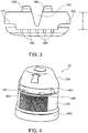
- Fig. 4 shows a perspective view of another embodiment of a dispensing closure according to the present invention. This embodiment is very similar to the first embodiment, similar or identical elements therefore bear the same reference numeral.
- this embodiment of the dispensing closure 10 has a base element 100, a flip-top lid 200 and a tamper-evident element 300.
- a base element 100 a flip-top lid 200 and a tamper-evident element 300.
- the tamper-evident element 300 of the dispensing closure 10 does not have a notch, but has weakening areas or weakening lines, which are provided at the inner side of the tamper-evident element 300, so that these weakening lines or areas cannot be seen in the perspective view of Fig. 4 .
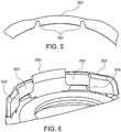
- Fig. 5 shows a partial cross-section through one embodiment of a tamper-evident element 300, which has, on its inner side, two weakening regions, being realized as weakening lines 350, extending over the complete height H of the tamper-evident element 300, therefore in a vertical direction.
- the weakening lines 350 have the effect that, if a force is exerted onto the tamper-evident element 300, the tamper-evident element is more susceptible to deformation, especially in the area of these weakening lines 350.
- Fig. 6 shows another embodiment of a tamper-evident element of a dispensing closure according to the present invention, while Fig. 6 is a perspective view showing parts of the dispensing closure and the tamper-evident element 300 from the inside.
- this embodiment of the tamper-evident element 300 has two weakening regions, being realized as weakening areas 352, directly adjacent, in a circumferential direction, to one locking extension 355, which extends in a vertically upward direction, i.e. into the direction of a flip-top lid when the flip-top lid is in its closed position.
- the weakening areas 352 extend about a certain angular distance in a circumferential direction over the tamper-evident element 300, in this embodiment by about 10. Generally, it is preferred that the weakening areas, here especially the weakening areas 352, extend about an angular distance in a circumferential direction being larger than the protrusions (440, see especially Fig. 1 ) of the flip-top lid (200, see also e.g. Fig. 1 or Fig. 4 ).
- these weakening areas also serve to enable a closing of the flip-top lid for the first time after manufacturing, so that the tamper-evident element 300 is not destroyed or damaged by the above-mentioned protrusions when closing the flip-top lid for the first time.
- these weakening areas 352 lead to the effect that the tamper-evident element 300 is especially susceptible to deformation at these weakening regions, so that such deformation can be easily seen by a user after the dispensing closure has been opened at least once, even if somebody would on purpose try to re-position the tamper-evident element after it has been torn off and after the frangible elements have been destroyed by a first opening of the flip-top lid.
- Fig. 7 shows some elements of an embodiment of the dispensing closure as shown in Fig. 6 , however, from the outside, and as can be seen in Fig. 7 , the weakening regions and weakening areas 352 are not visible from the outside.
- Fig. 7 very well shows the frangible elements 380, which attach the tamper-evident element 300 to the base element 100, more exactly to a shoulder region 180 of the base element 100.
- the shoulder region 180 is inclined such that it declines in a radially outward direction of the base element 100.
- the declination angle in this embodiment is about 20° relative to a horizontal direction.
- All frangible elements 380 are on the one side connected to the tamper-evident element 300 and on the other side to the declined shoulder region 180 of the base element 100.
- This declined shoulder region 180 has the effect that even in case a detached tamper-evident element 300 should be re-positioned onto said shoulder region after the frangible elements 380 have been destroyed, the tamper-evident element tends to automatically shift its position and slid away on the declined shoulder portion 180 simply by gravitational forces.
- Fig. 8 shows some elements of a still further embodiment of a dispensing closure according to the present invention, especially a tamper-evident element 300 and parts of the base 100.
- the tamper-evident element 300 of this embodiment is very similar to the tamper-evident element shown in Figs. 6 and 7 , however, the frangible elements 380 are partly different.
- frangible elements 380 have an hour-glass shape, in spite of the typically cubical form of the frangible elements used in such dispensing closures.
- the hour-glass shape of the frangible elements 380 leads to the effect that after destruction the remaining parts of the frangible elements 380 are more elongated than typically shaped frangible elements, and this will make it even more difficult to keep the tamper-evident element in its original position after the frangible elements 380 have been destroyed, even if a user should try to re-position the tamper-evident element on purpose after a destruction of the frangible elements 380.
- all frangible elements 380 are realized in an hour-glass shape.
- Fig. 9 shows a partial cross-section through another embodiment of a dispensing closure according to the present invention, which is very similar to the embodiment shown in Figs. 1 to 3 .
- the tamper-evident element 300 has locking extensions 360 (one of which is shown and visible in the cross-section of Fig. 9 ), while the locking extensions protrude into a recess 280 such that the locking extensions 360 are enclosed and covered to the outside so that a tampering of these locking extensions by a user is avoided.
Abstract
Description
- The present invention relates to a dispensing closure for a container with an opening and possibly with a spout for dispensing a fluid, while the dispensing closure comprises a flip-top lid, which can be moved between an opened position and a closed position.
- Typically such dispensing closures are designed such that the closures can be attached to a neck of a container, e.g. by screwing the dispensing closure onto the neck of a container, so that a fluid can be dispensed out of the container and through the opening or a spout of the dispensing closure.
- Such dispensing closures are used for many different purposes and are frequently used for containers which contain fluid media, especially drinks or other food products, but such dispensing closures can be also used for containers storing other fluids or viscous products. Such a dispensing closure is for example disclosed in
EP 1 503 942 B1 . Another closure is known fromFR 2 267 253 A1 - It is an object of the present invention to enhance such a closure as known in the prior art and especially in the above-mentioned document, especially with respect to its tamper-evident properties.
- This problem is solved by a dispensing closure according to claim 1, claims 2 to 15 refer to specifically advantageous realizations of such a dispensing closure.
- According to the present invention, the dispensing closure comprises a base element which can be attached to a neck of a container and which comprises a dispensing opening, a flip-top lid, being attached to said base element by a hinge and being movable between a closed position, in which the dispensing opening is closed by a closing element of said flip-top lid, and an opened position, in which said dispensing opening is at least partly opened such that a fluid can be dispensed through said dispensing opening, a tamper-evident element extending in a circumferential direction around at least a part of the circumference of said dispensing closure and being attached to a shoulder region of said base element by at least two frangible elements having a pre-determined breaking point.
- According to the present invention at least one of the two frangible elements has an hour-glass shape, wherein preferably some or more, preferably even all frangible elements have an hour-glass shape.
- This specific shape leads to the effect that the forces applied to the frangible elements during a first opening of the dispensing closures lead to specifically well visible and obvious deformations both of the remaining parts of the frangible elements and/or the tamper-evident element, when opening the dispensing closure for the first time.
- An hour-glass shape of the frangible elements also typically leads to the effects that after destruction the remaining parts of the frangible elements are more elongated than with otherwise shaped elements, which also leads to the effect that it is more difficult to keep the tamper-evident element in its original position after the frangible elements have been destroyed, even if a user should try this on purpose or should try to re-position the tamper-evident element.
- According to another, even independently inventive aspect, it is preferred that said flip-top lid has at least one opening or recession being arranged and dimensioned such that it encloses at least part of at least one locking extension of the tamper-evident element extending, from said tamper-evident element or an element or part thereof, at least partly into the direction of the flip-top lid, when said flip-top lid is in its closed position and said tamper-evident element is in its original position with the frangible elements being undestroyed.
- The direction into which the locking extension is at least partly extending, is, when viewing the closure in its upright position, a vertical direction. This vertical direction is normal to the circumferential direction. Typically these closures have a circular cross-section, so that the closures can be screwed onto a neck of a container, preferably by interrelated threads, typically an inner thread in the closure and an outer thread at the neck of a container.
- Preferably, said tamper-evident element has at least one weakening region, preferably in the vicinity of one of said at least one locking extension, said at least one weakening region extending at least partly over the height of the tamper-evident element, and/or said shoulder region of said base element, to which said frangible elements of said tamper-evident element are attached, is inclined such that it declines in an outward direction of the base element.
- When the closure is in its upright position and when the tamper-evident element is in its original position, namely before opening of the closure for the first time, also the tamper-evident element is in its upright position so that the height of the tamper-evident element is extending in a vertical direction.
- One advantage of such an embodiment is that the tamper-evident element of the inventive dispensing closure does, in a more obvious way show to the user, if and when the closure has been opened for the first time, especially by a more visual deformation of the tamper-evident element by itself and/or by a more visual deformation of the frangible elements and/or by a more visible shift of the position of the tamper-evident element in or at the dispensing closure, if the tamper-evident element should be still somehow located at the dispensing closure, e.g. also due to the fact that a user tries, on purpose, to re-position the tamper-evident element after a first opening of the closure.
- This even more enhances the tamper-evident capabilities of the dispensing closure and makes it even more obvious to a user, whether the dispensing closure has been opened at least once, even if the dispensing closures should have been opened in a very careful way or even with the intention of a user to hide that the dispensing closure has been opened already at least once, e.g. by trying to re-position the tamper-evident element which has been detached from the closure by a first opening.
- Especially the provision of a weakening region in the tamper-evident element, preferably in the vicinity of one of said at least one locking extensions extending at least partly over the height of the tamper-evident element, increases this advantageous effect, as especially in this region of the tamper-evident element a more visible deformation is created when a force is exerted onto the tamper-evident element when opening the dispensing closure for the first time.
- A shoulder region of said base element, to which said frangible elements of said tamper-evident element are attached, being inclined such that it declines in an outward direction, especially a radially outward direction, of the base element also ensures that there is a remarkably higher likelihood that the position of a tamper-evident element after a first opening of the dispensing closure, therefore after a destruction of at least one or some or all of the frangible elements, will be visibly different from the original position of the tamper-evident element with the frangible elements being undestroyed, even if somebody should try to put the tamper-evident element on purpose back into a position being close to such an original position, as the tamper-evident element will, due to the force of gravity, slide at least partly along the declined shoulder region. This is of specific advantage especially with dispensing closures having a tamper-evident element with a locking extension being enclosed at least partly by an opening or recession in a flip-top lid, while such an opening or recession in the flip-top lid and the corresponding locking extension also serves to avoid a manipulation of the dispensing closure and the tamper-evident element.
- In summary therefore, the features of the dispensing closure according to claim 1 serve to provide a very secure tamper-evident function and high quality properties, being even further enhanced over the already high security of existing closures.
- According to a preferred embodiment one of said at least one weakening region comprises either a notch extending over a part of the height of the tamper-evident element or comprises a weakening line, reducing the thickness of the tamper-evident element over at least part of the height of the tamper-evident element. These two possibilities for providing a weakening region are specifically of advantage, as it is easy to manufacture a dispensing closure with such a weakening region, preferably by injection molding, furthermore the realization of such weakening regions also decreases the weight of the dispensing closure, which is major cost factor for these mass products.
- By realizing the weakening region by any of these two preferred embodiments therefore both a reduction of costs and further increase of quality regarding the tamper-evident function is realized at the same time.
- Preferably the notch extends over a major part of the height of the tamper-evident element, preferably the notch extends at least over 50% of the height of the tamper-evident element, more preferably over at least 70% and even more preferably over at least 80% of the height of the tamper-evident element. In one preferred embodiment, the notch is provided on an upper side of the tamper-evident element, i.e. on the side which is directed to the flip-top lid, when this lid is its closed position. However, alternatively, it is also possible to provide the notch at a lower side of the tamper-evident element, i.e. at the side being directed to the base element.
- It is possible to provide only one notch, however, in another embodiment it is also possible to provide multiple notches.
- The "height" of the tamper-evident element is typically measured in a vertical direction, being a direction normal to the circumference of the dispensing closure.
- According to a specifically preferred embodiment a weakening line is provided on the inner side of the tamper-evident element, so that it is not visible to a user from the outside, when the dispensing closure is in its closed position and especially when it is not yet opened for the first time, while nevertheless the desired function, namely a deformation of the tamper-evident element is more easily created when opening the dispensing closure, i.e. when moving the flip-top lid from its closed position to an opened position for the first time, which will lead to a tearing off of the tamper-evident element, e.g. by one or more hooks which interact with for example openings or projections of the tamper-evident element in a way that during opening of the flip-top lid a force is exerted onto the tamper-evident element which destroys the frangible elements.
- In one preferred embodiment said tamper-evident element comprises two locking extensions, wherein said weakening region is provided, in a circumferential direction, between these two locking extensions. This realization further increases the susceptibility or sensitivity of the tamper-evident element to be deformed when the dispensing closure is opened for the first time. This effect is realized both when having a weakening region comprising a notch and/or when having a weakening region comprising a weakening line, as referred to above.
- In this respect it shall be noted that a weakening region can be also realized by both a notch and a weakening line, namely with a notch extending over a part of the height of the tamper-evident element, while a weakening line extending over another part and preferably over the remaining part of the height of the tamper-evident element. In one embodiment, a notch and a weakening line are provided at the same angular or circumferential position, however, it is also possible to provide at least one notch and/or at least one weakening line at different angular or circumferential positions of the tamper-evident element.
- In a specifically preferred embodiment a weakening region extends over the complete circumferential distance between two locking extensions. The larger the weakening region is, especially the more the weakening region extends in a circumferential direction, the more the above-mentioned effects, especially a deformation of the tamper-evident element is unavoidably created when the dispensing closure is opened for the first time, especially due to the force exerted onto the tamper-evident element by the opening and the thereby generated destruction of the frangible elements.
- According to another preferred embodiment said tamper-evident element comprises one or even only one locking extension and at least two weakening regions, which, in a circumferential direction of the tamper-evident element, are positioned preferably directly adjacent said one locking extension. This embodiment has the advantage that a lower number of locking extensions and possibly only one single locking extension is necessary, which again has advantages during the manufacturing process and decreases the weight of the dispensing closure, while on the other hand the susceptibility for deformation of the tamper-evident element is increased, especially by the close interrelationship of the locking extension and the weakening regions positioned directly adjacent to said locking extension, increasing the susceptibility to deformations when a force is applied.
- According to a preferred embodiment the dispensing closure has at least one frangible element in a circumferential position of said tamper-evident element where a weakening region is provided or in the vicinity of such a weakening region. This realization has the advantage that the force exerted onto the frangible element when opening the dispensing closure for the first time is directly transferred to the weakening region, also increasing the susceptibility to deformations.
- Similarly, and preferably in addition to the above-mentioned preferred realization, a preferred dispensing closure has a frangible element also positioned at the circumferential borders of at least one locking extension or in the direct vicinity thereof, as also this realization supports a better transfer of the force exerted especially on the frangible element during opening of the dispensing closure, thereby increasing susceptibility to deformation of the tamper-evident element.
- According to a preferred embodiment, the tamper-evident element of the dispensing closure comprises multiple weakening regions over the extension of the tamper-evident element in its circumferential direction. This realization has the advantage that the weakening effect of the weakening regions is provided at various parts of the circumference of the tamper-evident element, so that the susceptibility to deformation is increased at various parts of the tamper-evident element, so that a deformation is more likely even if the dispensing closure is opened for the first time by applying a force in different ways, depending on the activities of the user.
- According to a preferred embodiment, the number of frangible elements is concentrated in a certain area over the extension of the tamper-evident element.
- Especially the number of frangible elements per angular extension of the tamper-evident element in its circumferential dimension is higher in those circumferential angular regions, where a locking extension is provided, when compared to those angular circumferential regions where no locking extension of the tamper-evident element is provided.
- This specific realization has the advantage that the force exerted on the tamper-evident element is concentrated on a specific part of the tamper-evident element, so that also by this measurement the susceptibility to deformation is further increased.
- According to another specific realization of the dispensing closure according to the present invention, the shoulder region of said base element is declined in an outward direction, especially in a radially outward direction, of the dispensing closure, by an angle of 10° to 45° relative to a horizontal direction further preferably by an angle of 15° to 30 relative to the horizontal direction.
- This embodiment has the advantage that the tamper-evident element tends to automatically shift its position relative to the original position, in which the frangible elements are undestroyed, after a first opening of dispensing closure, simply by gravitational forces when the closure and/or the container is in its upright position, even if, possibly on purpose, a user tries to place the tamper-evident element into about the same position as its original position after having opened the dispensing closure for the first time or when not having opened the lid completely.
- These realizations therefore have a major effect on the tamper-evident capabilities, especially for devices which have the additional security feature of the locking extension of the tamper-evident element, which is partly covered by an opening or recession in the flip-top lid.
- According to a preferred realization said shoulder region of said base element is declined over at least the complete circumferential extension of the tamper-evident element, as this further enhances the above-mentioned effect and as this secures that any part of the tamper-evident element, after having been detached from the base element by destruction of the frangible element, at best rests on the declined shoulder region, so that independent of the specific position of the tamper-evident element, if not already fully removed from the closure, the above-mentioned effect is automatically supported by the gravitational forces.
- Further preferably all frangible elements are attached to said shoulder region of said base element in an area where the shoulder region is declined, which also supports the above-mentioned effect.
- These and other features and advantages of the present invention will become even more apparent by the following figures, partly schematically showing preferred embodiments of the dispensing closure according to the present invention or elements thereof.
- Fig. 1
- shows an embodiment of a dispensing closure according to the present invention in a perspective view, with the dispensing closure being in its original, un-opened position.
- Fig. 2
- shows the embodiment of a dispensing closure as in
Fig. 1 , in a position as it is manufactured e.g. by injection molding before a first closing of the flip-top lid, so that the tamper-evident element is still attached to the base element. - Fig. 3
- shows a part of a tamper-evident element of the embodiment of a dispensing closure as shown in
Figs. 1 and 2 ; - Fig. 4
- shows a further embodiment of a dispensing closure according to the present invention in a perspective view, with the dispensing closure being in its original, un-opened position.
- Fig. 5
- shows a partial cross-section through a tamper-evident element of the embodiment of a dispensing closure as shown in
Fig. 4 ; - Fig. 6
- shows a perspective view of parts of another embodiment of a dispensing closure according to the present invention, especially an embodiment of a tamper-evident element, which could be also e.g. used for an embodiment of the dispensing closure as shown in
Fig. 4 , the view showing especially the tamper-evident element from an inner side; - Fig. 7
- shows a perspective view of the embodiment shown in
Fig. 6 , the view showing the tamper-evident element from the outside; - Fig. 8
- shows parts of another embodiment of a dispensing closure according to the present invention, especially another embodiment of a tamper-evident element, and
- Fig. 9
- shows a partial cross-section of an embodiment of a dispensing closure according to the present invention with the dispensing closure being in its original, un-opened position.
-
Fig. 1 shows, in a schematic view, one embodiment of a dispensingclosure 10 according to the present invention. The dispensingclosure 10 comprises abase element 100, a flip-top lid 200 and a tamper-evident element 300. - As can be seen in
Fig. 2 , the flip-top lid 200 is attached to thebase 100 by ahinge 320, so that the flip-top lid 200 can be moved, by a user, between a closed position, seeFig. 1 and an opened position, seeFig. 2 . However, it has to be noted thatFig. 2 shows the embodiment of the dispensingclosure 10 in a condition before a first use, namely directly after manufacturing, with the flip-top lid still in the open position and the tamper-evident element 300 still being attached to thebase element 100 via frangible elements (see especiallyFig. 3 ), and before a first use, in other words in an intermediate manufacturing state, in order to better show the respective elements. - The tamper-
evident element 300 is, as can be especially well seen inFig. 3 , attached to thebase 100 via a number offrangible elements 380. - Although not explicitly shown in all of the figures, at least one of the
frangible elements 380 has an hour-glass shape. - The tamper-
evident element 300 further has two opening 345 or windows, at its lower edge, in which twoprotrusions 440 of the flip-top lid 200 extend, when the flip-top lid 200 is in its closed position as shown inFig. 3 . - If therefore the flip-
top lid 200 is moved from its closed position,Fig. 1 , into its opened position, theprotrusions 440, in engagement with theopenings 345 or windows of the tamper-evident element 300, will also lift the tamper-evident element 300 in an upward direction, so that the tamper-evident element 300 will be detached from thebase 100, thereby destroying thefrangible elements 380. - Normally the tamper-
evident element 300 will thereby be completely removed from the other parts of the closure, so that it is visible to all future users that the dispensing closure has been opened at least once. - Only for completion, it also has to be noted that the dispensing
closure 10 comprises another tamper-evident device 600 which is a tamper-evident device 600 for showing whether the dispensing closure, which can be attached to a neck of a container (not shown), has been removed at least once from the container. Such tamper-evident devices 600 are well-known in the art, and there is no specific relationship to the tamper-evident element 300, which is a major part of the dispensing closure according to the present invention. - As can be well seen in
Fig. 2 and especially inFig. 3 the tamper-evident element 300 also comprises two lockingextensions 360, which extend into the direction of the flip-top lid 300, when said flip-top lid 300 is in its closed position, whereby the two lockingextensions 360 are enclosed by parts of the flip-top lid, so that the lockingextensions 360 are enclosed or covered to the outside in order to avoid a tampering of these locking extensions by a user. With respect to a preferred realization of a flip-top lid being arranged such that the lockingextensions 360 are enclosed or covered to the outside, see especiallyFig. 9 . - As can be further well seen in
Fig. 3 the tamper-evident element 300 has a weakening region, which is realized in this embodiment as anotch 340. Thenotch 340 extends about a major part of the height H of the tamper-evident element 300, in this embodiment thenotch 340 extends over about 80% of the height H of the tamper-evident element 300, while the notch starts at an upper end or an upper edge of the tamper-evident element 300, in other words at the side of the tamper-evident element 300 which is directed to the flip-top lid 200 when the flip-top lid 200 is in its closed position. - Furthermore the weakening region, here the
notch 340, extends over the complete circumferential distance between the two lockingextensions 360, at least at an upper part of the tamper-evident element 300, and the width of thenotch 340 decreases in a downward direction, i.e. in a direction to thebase element 100. Thenotch 340 therefore is formed essentially in a V- or U shape. - With respect to
Fig. 3 it has to be mentioned that the protrusions (440, s.Fig. 1 ) of the flip-top lid 200 are not shown in order to enhance clarity of this figure, which especially shows the specific realization of the tamper-evident element 300, the two lockingextensions 360, thenotch 340 and some of thefrangible elements 380, which attach or fasten the tamper-evident element 300 to thebase 100. - The
notch 340 has the effect that, if a force is exerted onto the tamper-evident element 300, the tamper-evident element is more susceptible to deformation, especially in the area of thisnotch 340. -
Fig. 4 shows a perspective view of another embodiment of a dispensing closure according to the present invention. This embodiment is very similar to the first embodiment, similar or identical elements therefore bear the same reference numeral. - Also this embodiment of the dispensing
closure 10 according to the present invention has abase element 100, a flip-top lid 200 and a tamper-evident element 300. With respect to the functioning it is especially referred to the description of the embodiment shown inFigs. 1 to 3 , especially with respect to theprotrusions 440, interacting withopenings 345 or windows of the tamper-evident element 300. - However, as can be well seen in
Fig. 4 , the tamper-evident element 300 of the dispensingclosure 10 does not have a notch, but has weakening areas or weakening lines, which are provided at the inner side of the tamper-evident element 300, so that these weakening lines or areas cannot be seen in the perspective view ofFig. 4 . -
Fig. 5 shows a partial cross-section through one embodiment of a tamper-evident element 300, which has, on its inner side, two weakening regions, being realized as weakeninglines 350, extending over the complete height H of the tamper-evident element 300, therefore in a vertical direction. - The weakening lines 350 have the effect that, if a force is exerted onto the tamper-
evident element 300, the tamper-evident element is more susceptible to deformation, especially in the area of these weakeninglines 350. -
Fig. 6 shows another embodiment of a tamper-evident element of a dispensing closure according to the present invention, whileFig. 6 is a perspective view showing parts of the dispensing closure and the tamper-evident element 300 from the inside. - As can be well seen in
Fig. 6 , also this embodiment of the tamper-evident element 300 has two weakening regions, being realized as weakeningareas 352, directly adjacent, in a circumferential direction, to onelocking extension 355, which extends in a vertically upward direction, i.e. into the direction of a flip-top lid when the flip-top lid is in its closed position. - The weakening
areas 352 extend about a certain angular distance in a circumferential direction over the tamper-evident element 300, in this embodiment by about 10. Generally, it is preferred that the weakening areas, here especially the weakeningareas 352, extend about an angular distance in a circumferential direction being larger than the protrusions (440, see especiallyFig. 1 ) of the flip-top lid (200, see also e.g.Fig. 1 orFig. 4 ). - Beyond the purpose described above, these weakening areas also serve to enable a closing of the flip-top lid for the first time after manufacturing, so that the tamper-
evident element 300 is not destroyed or damaged by the above-mentioned protrusions when closing the flip-top lid for the first time. - However, also these weakening
areas 352 lead to the effect that the tamper-evident element 300 is especially susceptible to deformation at these weakening regions, so that such deformation can be easily seen by a user after the dispensing closure has been opened at least once, even if somebody would on purpose try to re-position the tamper-evident element after it has been torn off and after the frangible elements have been destroyed by a first opening of the flip-top lid. -
Fig. 7 shows some elements of an embodiment of the dispensing closure as shown inFig. 6 , however, from the outside, and as can be seen inFig. 7 , the weakening regions and weakeningareas 352 are not visible from the outside. - However,
Fig. 7 very well shows thefrangible elements 380, which attach the tamper-evident element 300 to thebase element 100, more exactly to ashoulder region 180 of thebase element 100. - As can be also well seen in
Fig. 7 , theshoulder region 180 is inclined such that it declines in a radially outward direction of thebase element 100. The declination angle in this embodiment is about 20° relative to a horizontal direction. - All
frangible elements 380 are on the one side connected to the tamper-evident element 300 and on the other side to the declinedshoulder region 180 of thebase element 100. - This declined
shoulder region 180 has the effect that even in case a detached tamper-evident element 300 should be re-positioned onto said shoulder region after thefrangible elements 380 have been destroyed, the tamper-evident element tends to automatically shift its position and slid away on the declinedshoulder portion 180 simply by gravitational forces. -
Fig. 8 shows some elements of a still further embodiment of a dispensing closure according to the present invention, especially a tamper-evident element 300 and parts of thebase 100. - The tamper-
evident element 300 of this embodiment is very similar to the tamper-evident element shown inFigs. 6 and7 , however, thefrangible elements 380 are partly different. - As can be well seen in
Fig. 8 , most of thefrangible elements 380 have an hour-glass shape, in spite of the typically cubical form of the frangible elements used in such dispensing closures. The hour-glass shape of thefrangible elements 380 leads to the effect that after destruction the remaining parts of thefrangible elements 380 are more elongated than typically shaped frangible elements, and this will make it even more difficult to keep the tamper-evident element in its original position after thefrangible elements 380 have been destroyed, even if a user should try to re-position the tamper-evident element on purpose after a destruction of thefrangible elements 380. - In another preferred embodiment, all
frangible elements 380 are realized in an hour-glass shape. -
Fig. 9 shows a partial cross-section through another embodiment of a dispensing closure according to the present invention, which is very similar to the embodiment shown inFigs. 1 to 3 . As can be well seen inFig. 9 , the tamper-evident element 300 has locking extensions 360 (one of which is shown and visible in the cross-section ofFig. 9 ), while the locking extensions protrude into arecess 280 such that the lockingextensions 360 are enclosed and covered to the outside so that a tampering of these locking extensions by a user is avoided. - The features of the present invention disclosed in the specification, the claims and/or in the accompanying drawings may, both separately and in any combination thereof, be material for realizing the invention in various forms thereof.
Claims (15)
- Dispensing closure comprising- a base element (100) which can be attached to a neck of a container and which comprises a dispensing opening,- a flip-top lid (200), being attached to said base element (100) by a hinge (320) and being movable between a closed position, in which the dispensing opening is closed by a closing element of said flip-top lid (200), and an opened position, in which said dispensing opening is at least partly opened such that a fluid can be dispensed through said dispensing opening,- a tamper-evident element (300) extending in a circumferential direction around at least a part of the circumference of said dispensing closure (10) and being attached to a shoulder region (180) of said base element (100) by at least two frangible elements (380) having a pre-determined breaking point,characterized in that at least one of the two frangible elements (380) has an hour-glass shape, wherein preferably all frangible elements (380) have an hour-glass shape.
- Dispensing closure according to claim 1,
said flip-top lid (200) having at least one opening or recession being arranged and dimensioned such that it encloses at least part of at least one locking extension (355) of the tamper-evident element (300) extending at least partly into the direction of the flip-top lid (200), when said flip-top lid (200) is in its closed position and said tamper-evident element (300) is in its original position with the frangible elements (380) being undestroyed,
wherein
said tamper-evident element (300) has at least one weakening region (340, 350, 352), preferably in the vicinity of one of said at least one locking extensions (355), said at least one weakening region (340, 350, 352) extending at least over a part of the height (H) of the tamper-evident element (300), and/or
said shoulder region (180) of said base element (100), to which said frangible elements (380) of said tamper-evident element (300) are attached, is inclined such that it declines in an outward direction of the base element (100). - Dispensing closure according to claim 2, wherein one of said at least one weakening regions comprises a notch (340) extending over a part of the height (H) of the tamper-evident element (300).
- Dispensing closure according to one of the claims 2 to 3, wherein one of said at least one weakening region (350, 352) comprises a weakening area (352) or line (350), reducing the thickness of the tamper-evident element (300) over at least part of the height of the tamper-evident element (300).
- Dispensing closure according to claim 4, wherein said weakening area (352) or line (350) is provided on the inner side of the tamper-evident element (300).
- Dispensing closure according to one of the claims 2 to 5, wherein said tamper-evident element (300) comprises two locking extensions (360) and wherein said weakening region (340) is provided, in a circumferential direction, between these two locking extensions (360).
- Dispensing closure according to claim 6, wherein said weakening region (340) extends over the complete circumferential distance between the two locking extensions (360).
- Dispensing closure according to one of the claims 1 to 5, wherein said tamper-evident element (300) comprises one or only one locking extension (355) and at least two weakening regions (352) which, in a circumferential direction of the tamper-evident element (300), are positioned directly adjacent said one locking extension (355).
- Dispensing closure according to one of the claims 2 to 8, having at least one frangible element (380) in a circumferential position of said tamper-evident element (300) where a weakening region (350) is provided or in the vicinity of such a weakening region (350).
- Dispensing closure according to one of the claims 2 to 9, having a frangible element (380) positioned, in a circumferential direction, at the circumferential borders of at least one locking extension (355) or in the direct vicinity thereof.
- Dispensing closure according to one of the preceding claims, comprising multiple weakening regions (350) over the extension of the tamper-evident element (300) in its circumferential direction.
- Dispensing closure according to one of the claims 2 to 11, wherein the number of frangible elements (380) per angular extension of the tamper-evident element (300) in its circumferential direction is higher in those circumferential angular regions where a locking extension is provided compared to those angular circumferential regions where no locking extension of the tamper-evident element (300) is provided.
- Dispensing closure according to one of the preceding claims, wherein said shoulder region (180) of said base element (100) is declined in an outward direction, preferably a radially outward direction, by an angle of 10° to 45° relative to a horizontal direction, preferably by an angle of 5° to 60° relative to the horizontal direction, preferably by an angle of 10° to 45°, and more preferably by an angle of 15° to 30°..
- Dispensing closure according to claim 13, wherein said shoulder region (180) is declined over at least the complete circumferential extension of the tamper-evident element (300).
- Dispensing closure according to one of the preceding claims, wherein all frangible elements (380) are attached to said shoulder region (180) of said base element (300) in an area where said shoulder region is declined.
Priority Applications (3)
| Application Number | Priority Date | Filing Date | Title |
|---|---|---|---|
| PL19186030T PL3578478T3 (en) | 2017-11-06 | 2017-11-06 | Dispensing closure for a fluid container |
| EP19186030.3A EP3578478B1 (en) | 2017-11-06 | 2017-11-06 | Dispensing closure for a fluid container |
| ES19186030T ES2860757T3 (en) | 2017-11-06 | 2017-11-06 | Dispensing closure for a fluid container |
Applications Claiming Priority (3)
| Application Number | Priority Date | Filing Date | Title |
|---|---|---|---|
| EP17793963.4A EP3548393B1 (en) | 2017-11-06 | 2017-11-06 | Dispensing closure for a fluid container |
| PCT/EP2017/078354 WO2019086132A1 (en) | 2017-11-06 | 2017-11-06 | Dispensing closure for a fluid container |
| EP19186030.3A EP3578478B1 (en) | 2017-11-06 | 2017-11-06 | Dispensing closure for a fluid container |
Related Parent Applications (2)
| Application Number | Title | Priority Date | Filing Date |
|---|---|---|---|
| EP17793963.4A Division-Into EP3548393B1 (en) | 2017-11-06 | 2017-11-06 | Dispensing closure for a fluid container |
| EP17793963.4A Division EP3548393B1 (en) | 2017-11-06 | 2017-11-06 | Dispensing closure for a fluid container |
Publications (2)
| Publication Number | Publication Date |
|---|---|
| EP3578478A1 true EP3578478A1 (en) | 2019-12-11 |
| EP3578478B1 EP3578478B1 (en) | 2021-01-27 |
Family
ID=60245115
Family Applications (2)
| Application Number | Title | Priority Date | Filing Date |
|---|---|---|---|
| EP17793963.4A Active EP3548393B1 (en) | 2017-11-06 | 2017-11-06 | Dispensing closure for a fluid container |
| EP19186030.3A Active EP3578478B1 (en) | 2017-11-06 | 2017-11-06 | Dispensing closure for a fluid container |
Family Applications Before (1)
| Application Number | Title | Priority Date | Filing Date |
|---|---|---|---|
| EP17793963.4A Active EP3548393B1 (en) | 2017-11-06 | 2017-11-06 | Dispensing closure for a fluid container |
Country Status (9)
| Country | Link |
|---|---|
| US (1) | US10562681B2 (en) |
| EP (2) | EP3548393B1 (en) |
| CN (1) | CN110099855B (en) |
| BR (1) | BR112018068813A2 (en) |
| ES (2) | ES2827400T3 (en) |
| MX (1) | MX2018014664A (en) |
| PL (2) | PL3548393T3 (en) |
| RU (1) | RU2741455C2 (en) |
| WO (1) | WO2019086132A1 (en) |
Families Citing this family (3)
| Publication number | Priority date | Publication date | Assignee | Title |
|---|---|---|---|---|
| US11396408B2 (en) | 2019-08-05 | 2022-07-26 | Yeti Coolers, Llc | Lid for container |
| USD914498S1 (en) * | 2019-09-19 | 2021-03-30 | Obrist Closures Switzerland Gmbh | Closure for a container neck |
| WO2021089105A1 (en) * | 2019-11-07 | 2021-05-14 | Aptar Freyung Gmbh | Closure device |
Citations (2)
| Publication number | Priority date | Publication date | Assignee | Title |
|---|---|---|---|---|
| FR2267253A1 (en) | 1974-04-11 | 1975-11-07 | Vosselle Charles | Security cap for bottle with threaded neck - has upper threaded part joined to smooth lower part by tear line |
| EP1503942A1 (en) | 2002-05-10 | 2005-02-09 | Seaquist-Löffler Kunststoffwerk GmbH | Hinged lid closure provided with a tamper-evident element for a container containing a free-flowing product |
Family Cites Families (14)
| Publication number | Priority date | Publication date | Assignee | Title |
|---|---|---|---|---|
| US4487324A (en) * | 1984-02-08 | 1984-12-11 | Seaquist Closures | Tamper-evident dispensing closure |
| FR2665140B1 (en) * | 1990-07-25 | 1992-11-13 | Astra Plastique | CAPPING DEVICE WITH IRREVERSIBLE ATTACHMENT TO THE NECK OF A CONTAINER. |
| US5547091A (en) * | 1991-11-27 | 1996-08-20 | Colgate-Palmolive Company | Dispensing container snap hinge closure |
| US5386918A (en) * | 1993-04-22 | 1995-02-07 | Colgate-Palmolive Co. | Closure with tamper evidence structure |
| ES1028707U (en) * | 1993-09-03 | 1995-03-01 | Novembal Sa | Screwcap with tamper evidence band, package provided with such a cap, method of making such a cap and such a package. |
| DE29512523U1 (en) * | 1995-08-03 | 1995-10-12 | Georg Menshen Gmbh & Co Kg | Container closure |
| US6644487B2 (en) * | 2001-08-17 | 2003-11-11 | Seaquist Closures Foreign, Inc. | Tamper-evident closure with break-off piece retention |
| US6766926B1 (en) * | 2002-07-29 | 2004-07-27 | Owens-Illinois Closure Inc. | Dispensing closure, package and method of manufacture |
| EP1768914B1 (en) * | 2004-07-16 | 2014-09-03 | Alcoa Closure Systems International, Inc. | Tamper-indicating dispensing closure |
| US7798348B2 (en) * | 2005-12-02 | 2010-09-21 | Berry Plastics Corporation | Child-resistant closure |
| US8028848B2 (en) * | 2007-06-22 | 2011-10-04 | Rexam Closure Systems Inc. | Non-removable closure/finish system |
| US20090107948A1 (en) * | 2007-10-24 | 2009-04-30 | Sigma Aldrich Company | Bottle and cap device |
| JP6102100B2 (en) * | 2012-07-10 | 2017-03-29 | 凸版印刷株式会社 | Stopper plug |
| CN204184712U (en) * | 2014-10-11 | 2015-03-04 | 孟州市怡通塑料制品有限责任公司 | Integrate shaped type Sports bottle cap |
-
2017
- 2017-11-06 EP EP17793963.4A patent/EP3548393B1/en active Active
- 2017-11-06 US US16/306,084 patent/US10562681B2/en active Active
- 2017-11-06 PL PL17793963T patent/PL3548393T3/en unknown
- 2017-11-06 ES ES17793963T patent/ES2827400T3/en active Active
- 2017-11-06 CN CN201780033100.6A patent/CN110099855B/en active Active
- 2017-11-06 BR BR112018068813A patent/BR112018068813A2/en not_active Application Discontinuation
- 2017-11-06 EP EP19186030.3A patent/EP3578478B1/en active Active
- 2017-11-06 WO PCT/EP2017/078354 patent/WO2019086132A1/en active Application Filing
- 2017-11-06 RU RU2018133706A patent/RU2741455C2/en active
- 2017-11-06 MX MX2018014664A patent/MX2018014664A/en unknown
- 2017-11-06 ES ES19186030T patent/ES2860757T3/en active Active
- 2017-11-06 PL PL19186030T patent/PL3578478T3/en unknown
Patent Citations (3)
| Publication number | Priority date | Publication date | Assignee | Title |
|---|---|---|---|---|
| FR2267253A1 (en) | 1974-04-11 | 1975-11-07 | Vosselle Charles | Security cap for bottle with threaded neck - has upper threaded part joined to smooth lower part by tear line |
| EP1503942A1 (en) | 2002-05-10 | 2005-02-09 | Seaquist-Löffler Kunststoffwerk GmbH | Hinged lid closure provided with a tamper-evident element for a container containing a free-flowing product |
| EP1503942B1 (en) * | 2002-05-10 | 2006-05-24 | Seaquist-Löffler Kunststoffwerk GmbH | Hinged lid closure provided with a tamper-evident element for a container containing a free-flowing product |
Also Published As
| Publication number | Publication date |
|---|---|
| RU2741455C2 (en) | 2021-01-26 |
| US10562681B2 (en) | 2020-02-18 |
| MX2018014664A (en) | 2019-06-10 |
| RU2018133706A (en) | 2020-03-25 |
| CN110099855A (en) | 2019-08-06 |
| EP3548393A1 (en) | 2019-10-09 |
| BR112018068813A2 (en) | 2019-07-09 |
| CN110099855B (en) | 2021-08-10 |
| PL3548393T3 (en) | 2021-04-19 |
| ES2827400T3 (en) | 2021-05-21 |
| ES2860757T3 (en) | 2021-10-05 |
| EP3578478B1 (en) | 2021-01-27 |
| WO2019086132A1 (en) | 2019-05-09 |
| PL3578478T3 (en) | 2021-08-09 |
| US20190135504A1 (en) | 2019-05-09 |
| RU2018133706A3 (en) | 2020-11-24 |
| EP3548393B1 (en) | 2020-09-09 |
Similar Documents
| Publication | Publication Date | Title |
|---|---|---|
| EP3784585B9 (en) | Closure | |
| RU2388673C2 (en) | Plug with indicator of unauthorised opening | |
| RU2309101C2 (en) | Synthetic polymer cap, sealing device and beverage package | |
| US4394918A (en) | Screw cap with tamper-proof hold ring | |
| EP1582475B1 (en) | Tamper evident closure assembly | |
| EP3578478B1 (en) | Dispensing closure for a fluid container | |
| RU2701589C2 (en) | Sealing device with unauthorized opening indication | |
| US20180134460A1 (en) | Re-closable container | |
| EP3670377B1 (en) | Capping device that is affixed to the neck of a container | |
| US20030102280A1 (en) | Device for plugging a threaded collar using a cap with a tamperproof ring | |
| EA012670B1 (en) | A tamper evident closure for bottles containing valuable drinks | |
| WO2009047626A2 (en) | Anti-adulteration closure device for bottles | |
| EP2114788B1 (en) | Tamper evident closure | |
| US6698605B2 (en) | Modified bottle neck for use with child resistant caps | |
| EP2088091B1 (en) | Capsule for the closure of bottles | |
| JPS60123355A (en) | Unjust unsealing display cover | |
| US2054034A (en) | Container closure means | |
| EP1636110B1 (en) | Closure device for containers of liquids, particularly bottles for liquors | |
| EP3093256B1 (en) | Antifilling pourer for bottle | |
| ITGE20090035A1 (en) | "SEALING ASSEMBLY OF A METAL CONTAINER FORMED BY A CLOSURE AND ITS LID CONTAINER" | |
| EP2208684A1 (en) | Air intake valve for containers containing liquid products | |
| EP3738900B1 (en) | Container, especially for medicines | |
| JP2011523921A (en) | Screw closure for bottle | |
| US20230399149A1 (en) | Closure cap and container neck for preventing detachment of a tamperevident strip | |
| RU2488534C1 (en) | Cap with rotary cover for bottle sealing |
Legal Events
| Date | Code | Title | Description |
|---|---|---|---|
| PUAI | Public reference made under article 153(3) epc to a published international application that has entered the european phase |
Free format text: ORIGINAL CODE: 0009012 |
|
| STAA | Information on the status of an ep patent application or granted ep patent |
Free format text: STATUS: THE APPLICATION HAS BEEN PUBLISHED |
|
| AC | Divisional application: reference to earlier application |
Ref document number: 3548393 Country of ref document: EP Kind code of ref document: P |
|
| AK | Designated contracting states |
Kind code of ref document: A1 Designated state(s): AL AT BE BG CH CY CZ DE DK EE ES FI FR GB GR HR HU IE IS IT LI LT LU LV MC MK MT NL NO PL PT RO RS SE SI SK SM TR |
|
| AX | Request for extension of the european patent |
Extension state: BA ME |
|
| STAA | Information on the status of an ep patent application or granted ep patent |
Free format text: STATUS: REQUEST FOR EXAMINATION WAS MADE |
|
| 17P | Request for examination filed |
Effective date: 20200304 |
|
| RBV | Designated contracting states (corrected) |
Designated state(s): AL AT BE BG CH CY CZ DE DK EE ES FI FR GB GR HR HU IE IS IT LI LT LU LV MC MK MT NL NO PL PT RO RS SE SI SK SM TR |
|
| GRAP | Despatch of communication of intention to grant a patent |
Free format text: ORIGINAL CODE: EPIDOSNIGR1 |
|
| STAA | Information on the status of an ep patent application or granted ep patent |
Free format text: STATUS: GRANT OF PATENT IS INTENDED |
|
| INTG | Intention to grant announced |
Effective date: 20200903 |
|
| GRAS | Grant fee paid |
Free format text: ORIGINAL CODE: EPIDOSNIGR3 |
|
| GRAA | (expected) grant |
Free format text: ORIGINAL CODE: 0009210 |
|
| STAA | Information on the status of an ep patent application or granted ep patent |
Free format text: STATUS: THE PATENT HAS BEEN GRANTED |
|
| AC | Divisional application: reference to earlier application |
Ref document number: 3548393 Country of ref document: EP Kind code of ref document: P |
|
| AK | Designated contracting states |
Kind code of ref document: B1 Designated state(s): AL AT BE BG CH CY CZ DE DK EE ES FI FR GB GR HR HU IE IS IT LI LT LU LV MC MK MT NL NO PL PT RO RS SE SI SK SM TR |
|
| REG | Reference to a national code |
Ref country code: GB Ref legal event code: FG4D |
|
| REG | Reference to a national code |
Ref country code: CH Ref legal event code: EP |
|
| REG | Reference to a national code |
Ref country code: AT Ref legal event code: REF Ref document number: 1358165 Country of ref document: AT Kind code of ref document: T Effective date: 20210215 |
|
| REG | Reference to a national code |
Ref country code: IE Ref legal event code: FG4D |
|
| REG | Reference to a national code |
Ref country code: DE Ref legal event code: R096 Ref document number: 602017032320 Country of ref document: DE |
|
| REG | Reference to a national code |
Ref country code: NL Ref legal event code: MP Effective date: 20210127 |
|
| REG | Reference to a national code |
Ref country code: LT Ref legal event code: MG9D |
|
| REG | Reference to a national code |
Ref country code: AT Ref legal event code: MK05 Ref document number: 1358165 Country of ref document: AT Kind code of ref document: T Effective date: 20210127 |
|
| PG25 | Lapsed in a contracting state [announced via postgrant information from national office to epo] |
Ref country code: GR Free format text: LAPSE BECAUSE OF FAILURE TO SUBMIT A TRANSLATION OF THE DESCRIPTION OR TO PAY THE FEE WITHIN THE PRESCRIBED TIME-LIMIT Effective date: 20210428 Ref country code: FI Free format text: LAPSE BECAUSE OF FAILURE TO SUBMIT A TRANSLATION OF THE DESCRIPTION OR TO PAY THE FEE WITHIN THE PRESCRIBED TIME-LIMIT Effective date: 20210127 Ref country code: HR Free format text: LAPSE BECAUSE OF FAILURE TO SUBMIT A TRANSLATION OF THE DESCRIPTION OR TO PAY THE FEE WITHIN THE PRESCRIBED TIME-LIMIT Effective date: 20210127 Ref country code: BG Free format text: LAPSE BECAUSE OF FAILURE TO SUBMIT A TRANSLATION OF THE DESCRIPTION OR TO PAY THE FEE WITHIN THE PRESCRIBED TIME-LIMIT Effective date: 20210427 Ref country code: PT Free format text: LAPSE BECAUSE OF FAILURE TO SUBMIT A TRANSLATION OF THE DESCRIPTION OR TO PAY THE FEE WITHIN THE PRESCRIBED TIME-LIMIT Effective date: 20210527 Ref country code: NO Free format text: LAPSE BECAUSE OF FAILURE TO SUBMIT A TRANSLATION OF THE DESCRIPTION OR TO PAY THE FEE WITHIN THE PRESCRIBED TIME-LIMIT Effective date: 20210427 Ref country code: LT Free format text: LAPSE BECAUSE OF FAILURE TO SUBMIT A TRANSLATION OF THE DESCRIPTION OR TO PAY THE FEE WITHIN THE PRESCRIBED TIME-LIMIT Effective date: 20210127 |
|
| PG25 | Lapsed in a contracting state [announced via postgrant information from national office to epo] |
Ref country code: AT Free format text: LAPSE BECAUSE OF FAILURE TO SUBMIT A TRANSLATION OF THE DESCRIPTION OR TO PAY THE FEE WITHIN THE PRESCRIBED TIME-LIMIT Effective date: 20210127 Ref country code: LV Free format text: LAPSE BECAUSE OF FAILURE TO SUBMIT A TRANSLATION OF THE DESCRIPTION OR TO PAY THE FEE WITHIN THE PRESCRIBED TIME-LIMIT Effective date: 20210127 Ref country code: SE Free format text: LAPSE BECAUSE OF FAILURE TO SUBMIT A TRANSLATION OF THE DESCRIPTION OR TO PAY THE FEE WITHIN THE PRESCRIBED TIME-LIMIT Effective date: 20210127 Ref country code: RS Free format text: LAPSE BECAUSE OF FAILURE TO SUBMIT A TRANSLATION OF THE DESCRIPTION OR TO PAY THE FEE WITHIN THE PRESCRIBED TIME-LIMIT Effective date: 20210127 |
|
| PG25 | Lapsed in a contracting state [announced via postgrant information from national office to epo] |
Ref country code: IS Free format text: LAPSE BECAUSE OF FAILURE TO SUBMIT A TRANSLATION OF THE DESCRIPTION OR TO PAY THE FEE WITHIN THE PRESCRIBED TIME-LIMIT Effective date: 20210527 |
|
| REG | Reference to a national code |
Ref country code: DE Ref legal event code: R097 Ref document number: 602017032320 Country of ref document: DE |
|
| PG25 | Lapsed in a contracting state [announced via postgrant information from national office to epo] |
Ref country code: SM Free format text: LAPSE BECAUSE OF FAILURE TO SUBMIT A TRANSLATION OF THE DESCRIPTION OR TO PAY THE FEE WITHIN THE PRESCRIBED TIME-LIMIT Effective date: 20210127 Ref country code: EE Free format text: LAPSE BECAUSE OF FAILURE TO SUBMIT A TRANSLATION OF THE DESCRIPTION OR TO PAY THE FEE WITHIN THE PRESCRIBED TIME-LIMIT Effective date: 20210127 |
|
| PG25 | Lapsed in a contracting state [announced via postgrant information from national office to epo] |
Ref country code: DK Free format text: LAPSE BECAUSE OF FAILURE TO SUBMIT A TRANSLATION OF THE DESCRIPTION OR TO PAY THE FEE WITHIN THE PRESCRIBED TIME-LIMIT Effective date: 20210127 Ref country code: SK Free format text: LAPSE BECAUSE OF FAILURE TO SUBMIT A TRANSLATION OF THE DESCRIPTION OR TO PAY THE FEE WITHIN THE PRESCRIBED TIME-LIMIT Effective date: 20210127 Ref country code: RO Free format text: LAPSE BECAUSE OF FAILURE TO SUBMIT A TRANSLATION OF THE DESCRIPTION OR TO PAY THE FEE WITHIN THE PRESCRIBED TIME-LIMIT Effective date: 20210127 |
|
| PLBE | No opposition filed within time limit |
Free format text: ORIGINAL CODE: 0009261 |
|
| STAA | Information on the status of an ep patent application or granted ep patent |
Free format text: STATUS: NO OPPOSITION FILED WITHIN TIME LIMIT |
|
| 26N | No opposition filed |
Effective date: 20211028 |
|
| PG25 | Lapsed in a contracting state [announced via postgrant information from national office to epo] |
Ref country code: AL Free format text: LAPSE BECAUSE OF FAILURE TO SUBMIT A TRANSLATION OF THE DESCRIPTION OR TO PAY THE FEE WITHIN THE PRESCRIBED TIME-LIMIT Effective date: 20210127 |
|
| PG25 | Lapsed in a contracting state [announced via postgrant information from national office to epo] |
Ref country code: SI Free format text: LAPSE BECAUSE OF FAILURE TO SUBMIT A TRANSLATION OF THE DESCRIPTION OR TO PAY THE FEE WITHIN THE PRESCRIBED TIME-LIMIT Effective date: 20210127 |
|
| PG25 | Lapsed in a contracting state [announced via postgrant information from national office to epo] |
Ref country code: IS Free format text: LAPSE BECAUSE OF FAILURE TO SUBMIT A TRANSLATION OF THE DESCRIPTION OR TO PAY THE FEE WITHIN THE PRESCRIBED TIME-LIMIT Effective date: 20210527 |
|
| PG25 | Lapsed in a contracting state [announced via postgrant information from national office to epo] |
Ref country code: MC Free format text: LAPSE BECAUSE OF FAILURE TO SUBMIT A TRANSLATION OF THE DESCRIPTION OR TO PAY THE FEE WITHIN THE PRESCRIBED TIME-LIMIT Effective date: 20210127 |
|
| REG | Reference to a national code |
Ref country code: CH Ref legal event code: PL |
|
| PG25 | Lapsed in a contracting state [announced via postgrant information from national office to epo] |
Ref country code: LU Free format text: LAPSE BECAUSE OF NON-PAYMENT OF DUE FEES Effective date: 20211106 Ref country code: CZ Free format text: LAPSE BECAUSE OF NON-PAYMENT OF DUE FEES Effective date: 20211106 Ref country code: BE Free format text: LAPSE BECAUSE OF NON-PAYMENT OF DUE FEES Effective date: 20211130 |
|
| REG | Reference to a national code |
Ref country code: BE Ref legal event code: MM Effective date: 20211130 |
|
| PG25 | Lapsed in a contracting state [announced via postgrant information from national office to epo] |
Ref country code: LI Free format text: LAPSE BECAUSE OF NON-PAYMENT OF DUE FEES Effective date: 20211130 Ref country code: CH Free format text: LAPSE BECAUSE OF NON-PAYMENT OF DUE FEES Effective date: 20211130 |
|
| PG25 | Lapsed in a contracting state [announced via postgrant information from national office to epo] |
Ref country code: IE Free format text: LAPSE BECAUSE OF NON-PAYMENT OF DUE FEES Effective date: 20211106 |
|
| P01 | Opt-out of the competence of the unified patent court (upc) registered |
Effective date: 20230509 |
|
| PG25 | Lapsed in a contracting state [announced via postgrant information from national office to epo] |
Ref country code: NL Free format text: LAPSE BECAUSE OF NON-PAYMENT OF DUE FEES Effective date: 20210127 Ref country code: CY Free format text: LAPSE BECAUSE OF FAILURE TO SUBMIT A TRANSLATION OF THE DESCRIPTION OR TO PAY THE FEE WITHIN THE PRESCRIBED TIME-LIMIT Effective date: 20210127 |
|
| PG25 | Lapsed in a contracting state [announced via postgrant information from national office to epo] |
Ref country code: HU Free format text: LAPSE BECAUSE OF FAILURE TO SUBMIT A TRANSLATION OF THE DESCRIPTION OR TO PAY THE FEE WITHIN THE PRESCRIBED TIME-LIMIT; INVALID AB INITIO Effective date: 20171106 |
|
| PGFP | Annual fee paid to national office [announced via postgrant information from national office to epo] |
Ref country code: GB Payment date: 20231121 Year of fee payment: 7 |
|
| PGFP | Annual fee paid to national office [announced via postgrant information from national office to epo] |
Ref country code: ES Payment date: 20231218 Year of fee payment: 7 |
|
| PGFP | Annual fee paid to national office [announced via postgrant information from national office to epo] |
Ref country code: IT Payment date: 20231124 Year of fee payment: 7 Ref country code: FR Payment date: 20231123 Year of fee payment: 7 Ref country code: DE Payment date: 20231127 Year of fee payment: 7 |