EP3578400B1 - Abdeckelement - Google Patents
Abdeckelement Download PDFInfo
- Publication number
- EP3578400B1 EP3578400B1 EP18175893.9A EP18175893A EP3578400B1 EP 3578400 B1 EP3578400 B1 EP 3578400B1 EP 18175893 A EP18175893 A EP 18175893A EP 3578400 B1 EP3578400 B1 EP 3578400B1
- Authority
- EP
- European Patent Office
- Prior art keywords
- cover element
- groove
- shaping
- foam
- area
- Prior art date
- Legal status (The legal status is an assumption and is not a legal conclusion. Google has not performed a legal analysis and makes no representation as to the accuracy of the status listed.)
- Not-in-force
Links
Images
Classifications
-
- B—PERFORMING OPERATIONS; TRANSPORTING
- B60—VEHICLES IN GENERAL
- B60J—WINDOWS, WINDSCREENS, NON-FIXED ROOFS, DOORS, OR SIMILAR DEVICES FOR VEHICLES; REMOVABLE EXTERNAL PROTECTIVE COVERINGS SPECIALLY ADAPTED FOR VEHICLES
- B60J5/00—Doors
- B60J5/04—Doors arranged at the vehicle sides
- B60J5/0412—Lower door structure
- B60J5/0418—Water or sound barrier, e.g. watershields or seals between dry/wet compartment, sound or vibration dampers
Definitions
- the present invention relates to a cover element for covering inner surface areas of the vehicle body, for. B. the inside of the door or door panel, such as in US 2017/113521 A1 disclosed.
- Cover elements can e.g. B. so-called acoustic cover, assembly carrier (AGT) or intermediate elements.
- AKT assembly carrier
- Such cover elements cover an interior of a vehicle body and must therefore be prepared to form a wet-dry area separation.
- the cover elements serve to avoid or reduce internal noise.
- Acoustic covers are installed in the area of the inside of a vehicle door and ensure wet-dry area separation in this area.
- cover elements are sealed.
- the sealing function is ensured by a preferably circumferential sealing element provided on the cover element.
- a circumferential prefabricated sealing ring can be inserted into a corresponding groove in the cover element.
- a cable harness has to be inserted laterally into the area of the cover element, with the result that a cable lead-through has to be carried out at the edge area of the cover element in the area of the seal. If tightness is not guaranteed in this area, water vapor, moisture or moisture can penetrate into the interior of the cover element and damage the electrical or electronic components there. This is a problem area where leaks can occur under certain circumstances.
- the object of the present invention is to provide a cover element which ensures an improved sealing effect in the area of a cable bushing.
- a foam contour bead is provided in the elongated groove.
- a foam contour bead is a foam-like sealing material which, while still flowing, is successively introduced into the groove along the course of the groove and cures there.
- the use of a foam contour bead creates the advantage that the cover element according to the invention can already be designed and supplied as a prefabricated combination element (cover and seal). The seals therefore no longer have to be assembled by the car manufacturer or have to be provided separately. This can minimize production costs for car production.
- At least one shaped projection provided in the region of the groove of the groove serves to thicken or change the foam contour bead in the region of the bulge for a cable bushing and thus to optimize the tightness of the cover element in the region of the cable bushing.
- the molded projection thus ensures an improved shape of the foam contour bead in the area of the cable duct and, as a result, an improved closure of the interior of the area to be covered by the cover element.
- a plurality of molded projections are
- the shape projection is expediently shaped and / or oriented in such a way that the flow of liquid, viscous or viscous foam is delayed during the (generally automated) application along the groove. This avoids gravity-related differences in thickness of the foam contour bead that forms when it is applied and / or special areas are formed which change a z. B. justify thickened area.
- the molded projection is located only in the flank area of the groove, whereas no projections are provided in the bottom area of the groove, foam of the foam contour bead is increasingly accumulated in the flank area of the groove. As a result, a thickening of the foam contour bead can form in the respective flank area of the groove, which leads to an improved sealing of the lateral area of the foam contour bead towards the incoming cable harness.
- a plurality of shaped projections are arranged one behind the other when viewed in the longitudinal direction of the groove. This allows the formation of the shape of the foam contour bead
- the number of shaped projections in the respective flank area can either be identical or different. For example, more individual molded projections can be provided on one flank of the groove than on the opposite flank area. In this way, the desired course and the thickness of the foam contour bead can be "controlled".
- the shaped projection preferably extends transversely to the course of the groove.
- the shaped projections can be arranged at an essentially equal distance from one another.
- the invention ensures that the molded projection can be molded into the material of the acoustic cover element, that is, it can be an integral part.
- the shaped projections are preferably knobs, ribs or webs.
- the foam contour bead is captively connected to the cover element. It is preferably glued to the groove.
- the cover element including the molded projections can be provided as a die-cast, preferably based on aluminum or as an injection molded part, preferably made of plastic, or as a laminated fiber-reinforced part.
- the foam contour bead is a viscous, flowable material in the application state, which hardens after being introduced into the groove and at the same time forms a connection with the cover element.
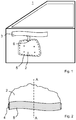
- Fig. 1 shows with the reference numeral 1 the interior of a (bare) car door with a cover element 2 attached to the inside of the car door.
- B. a so-called acoustic cover element.
- the cover element 2 serves on the one hand to ensure wet / dry separation, and on the other hand it also serves to stiffen the door area.
- the cover element 2 can alternatively be an assembly carrier (AGT).
- a “mechanical unit carrier” is a mechanical carrier for a functional device, for example for a window regulator motor (not shown) or the like.
- Such cover elements 2 can be designed as die-cast (e.g. aluminum die-cast) or injection-molded parts (e.g. plastic injection-molded parts) and / or as laminated fiber mats or single-fiber or fiber bundle-reinforced parts. You will use z. B. connectors or the like. Fixed to the car door.
- Fig. 1 also shows part of a cable harness 3 running along the inside of the car door, in which individual cables are combined. Part of the cable is branched off from the cable harness 3 and led into the area below the cover element 2.
- z. B. are a window motor or another electrical or electronic unit.
- the cover element 2 has an in Fig. 1 Dashed, full-circumferential sealing device, which is in the assembled state between the base body of the cover element 2 and the surface of the car door 1 and ensures a circumferential seal.
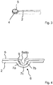
- a longitudinal groove 4 is formed, which is intended to receive a foam contour bead 5.
- the foam contour bead 5 is usually introduced into the groove 4 in an automated process, in which case the material of the foam contour bead 5 is liquid and only solidifies afterwards.
- an adhesive or adhesive connection with the material of the cover element 2 is established in the area of the groove 4.
- the foam contour bead 5 has, as from Fig. 3 evident, viewed in cross section, a rounded or oval shape.
- the foam contour bead 5 thus introduced thus forms an integral part of the cover element 2
- the cover element 2 can already be pre-assembled with the foam contour bead 5 as an integrated seal, as a result of which assembly processes for a seal are not required at the car manufacturer.
- the material of the foam contour bead 5 is continuously applied into the groove 4 by an injection nozzle (not shown) moving along the groove 4.
- the cover element 2 forms a bulge 6 for the cable bushing, so that the groove 4 as from Fig. 4 evidently extends beyond the bulge 6.
- a plurality of molded projections preferably oriented transversely to the course of the groove 4, are provided in the groove 4, which bring about a resistance to the flow behavior of the foam of the foam contour bead 5 in the still liquid state.
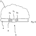
- a plurality of molded projections in the form of ribs 9 are provided, which according to Fig. 5 extend transversely to the longitudinal extent of the groove 4, specifically in each flank region 7a, 7b of the bulge 6.
- no molded projections are provided in the bottom region of the bulge 6.
- the projections can be arranged at the same distance from each other. If required, more shape projections can also be provided on one flank area, for example 7a, than in the opposite flank area 7b. This is related to the orientation of the entry of the liquid or viscous foam. At the in Fig. 4 shown embodiment, the foam is introduced into the groove 4 from the right to the left side.
- Fig. 4 it can be seen how the foam contour bead 5 is formed due to the presence of the molded projections in the region of the bulge 6.
- the shaped projections cause a thickening 8a, 8b of foam contour bead 5 in the respective edge area 7a, 7b of the bulge 6, which enables an optimal sealing of the cable in the area of the cable duct.
- the cover element 2 according to the invention in the region of the bulge 6 with a cable bushing (not shown in the figures) installed the foam contour bead 5 nestles optimally in the side area of the cable duct both on the cable duct and on the vehicle door 1 and ensures an effective seal in this problematic area.
Landscapes
- Engineering & Computer Science (AREA)
- Mechanical Engineering (AREA)
- Vehicle Interior And Exterior Ornaments, Soundproofing, And Insulation (AREA)
Description
- Die vorliegende Erfindung betrifft ein Abdeckelement zum Abdecken von Innenflächenbereichen von Fahrzeugkarosserie z. B. der Innenseite der Tür bzw. des Türblechs, wie z.B. in
US 2017/113521 A1 offenbart. Abdeckelemente können z. B. sogenannte Akustikdeckel, Aggregatträger (AGT) oder Zwischenelemente sein. Derartige Abdeckelemente decken einen Innenbereich einer Fahrzeugkarosserie ab und müssen deshalb dazu hergerichtet sein, eine Nass-Trockenbereichstrennung zu bilden. Ferner dienen die Abdeckelemente zur Vermeidung bzw. Reduzierung einer Innengeräuschbildung. Akustikdeckel werden im Bereich der Innenseite einer Fahrzeugtür montiert und gewährleisten in diesem Bereich eine Nass-Trockenbereichstrennung. - Zur Gewährleistung einer Nass-Trockenbereichstrennung werden Abdeckelemente dichtend befestigt. Die Dichtfunktion wird durch ein am Abdeckelement vorgesehenes vorzugsweise umlaufendes Dichtelement gewährleistet. Hierzu kann beispielsweise ein umlaufender vorgefertigter Dichtring in eine entsprechende Nut des Abdeckelements eingelegt werden. Je nach den konstruktiven Gegebenheiten kann es vorkommen, dass eine Kabelstrang seitlich in den Bereich des Abdeckelements eingeführt werden muss, mit der Folge, dass am Randbereich des Abdeckelements im Bereich der Dichtung eine Kabeldurchführung vorgenommen werden muss. Ist eine Dichtigkeit in diesem Bereich nicht sicher gewährleistet, kann Wasserdampf, Feuchtigkeit bzw. Nässe in das Innere des Abdeckelements eindringen und dort zu einer Schädigung der elektrischen oder elektronischen Bauteilen führen. Dies stellt eine Problemzone dar, bei der es unter bestimmten Umständen zu Undichtigkeiten kommen kann.
- Die Aufgabe der vorliegenden Erfindung besteht darin, ein Abdeckelement zur Verfügung zu stellen, welches eine verbesserte Dichtwirkung im Bereich einer Kabeldurchführung gewährleistet.
- Die vorstehende Aufgabe wird durch die Merkmale des Anspruchs 1 gelöst. Zweckmäßige Ausgestaltungen der Erfindung sind in den Unteransprüchen beansprucht.
- Erfindungsgemäß ist in der länglichen Nut eine Schaumkonturraupe vorgesehen. Eine Schaumkonturraupe ist ein schaumartiges Dichtungsmaterial, welches in noch fließfähigem Zustand entlang des Verlaufs der Nut sukzessive in Letztere eingebracht wird und dort aushärtet. Durch die Verwendung einer Schaumkonturraupe wird der Vorteil geschaffen, dass das erfindungsgemäße Abdeckelement bereits als vorkonfektioniertes Kombinationselement (Abdeckung und Dichtung) konzipiert und zugeliefert werden kann. Die Dichtungen müssen daher nicht mehr beim PKW-Hersteller montiert werden bzw. erst separat bereitgestellt werden. Produktionskosten bei der PKW-Herstellung können hierdurch minimiert werden. Mindestens ein im Bereich der Ausbauchung der Nut vorgesehener Formvorsprung dient dazu, die Schaumkonturraupe im Bereich der Ausbauchung für eine Kabeldurchführung zu verdicken bzw. zu verändern und so die Dichtigkeit des Abdeckelements im Bereich der Kabeldurchführung zu optimieren. Der Formvorsprung gewährleistet damit eine verbesserte Ausprägung der Schaumkonturraupe im Bereich der Kabeldurchführung und als Folge davon einen verbesserten Abschluss des Inneren des vom Abdeckelement abzudeckenden Bereichs. Vorzugsweise sind mehrere Formvorsprünge vorgesehen.
- Zweckmäßigerweise ist der Formvorsprung derart geformt und/oder orientiert, dass das Fließen von flüssigem, zähflüssigem oder viskosem Schaum während des (in der Regel automatisierten) Auftrags entlang der Nut verzögert wird. Hierdurch werden schwerkraftbedingte Dickenunterschiede der sich beim Aufbringen bildenden Schaumkonturraupe vermieden und/oder besondere Bereiche gebildet, die eine im Vergleich zum restlichen Verlauf der Schaumkonturraupe veränderten z. B. verdickten Bereich begründen.
- Dadurch, dass sich der Formvorsprung lediglich im Flankenbereich der Nut befindet, wohingegen im Bodenbereich der Nut keine Vorsprünge vorgesehen sind, wird im Flankenbereich der Nut vermehrt Schaum der Schaumkonturraupe aufgestaut. Hierdurch kann sich eine Verdickung der Schaumkonturraupe im jeweiligen Flankenbereich der Nut ausbilden, die zu einer verbesserten Abdichtung des seitlichen Bereichs der Schaumkonturraupe hin zu dem einlaufenden Kabelstrang führt.
- Zweckmäßigerweise sind mehrere Formvorsprünge in Längsrichtung der Nut betrachtet hintereinander angeordnet. Hierdurch kann die Ausbildung der Form der Schaumkonturraupe
- Die Anzahl der Formvorsprünge im jeweiligen Flankenbereich kann entweder identisch oder auch unterschiedlich sein. Beispielsweise können auf der einen Flanke der Nut mehr einzelne Formvorsprünge vorgesehen sein als auf dem gegenüberliegenden Flankenbereich. Hierdurch lässt sich der gewünschte Verlauf und die Dicke der Schaumkonturraupe "steuern".
- Vorzugsweise erstrecken sich der Formvorsprungquer zum Verlauf der Nut.
- Ferner können die Formvorsprünge untereinander in einem zumindest im Wesentlichen gleichen Abstand zueinander angeordnet sein.
- Die Erfindung gewährleistet es, dass der Formvorsprung jeweils in das Material des Akustik-Abdeckelements eingeformt sein also integraler Bestandteil sein kann.
- Bei den Formvorsprüngen handelt es sich vorzugsweise um Noppen, Rippen oder Stege.
- Die Schaumkonturraupe ist unverlierbar mit dem Abdeckelement verbunden. Vorzugsweise ist sie mit der Nut verklebt.
- Das Abdeckelement einschließlich der Formvorsprünge kann als Druckguss, vorzugsweise auf Basis von Aluminium oder als Spritzgießteil, vorzugsweise aus Kunststoff, oder als laminiertes faserverstärktes Teil vorgesehen sein.
- Bei der Schaumkonturraupe handelt es sich um im Applikationszustand fließfähiges, zähfließfähiges Material, welches nach dem Einbringen in die Nut aushärtet und gleichzeitig eine Verbindung mit dem Abdeckelement eingeht.
- Nachstehend wird anhand eines Ausführungsbeispiels die vorliegende Erfindung näher erläutert. Es zeigen:
- Fig. 1
- in stark vereinfachter schematischer Darstellungsweise ein Abdeckelement, welches im Bereich der Innenseite einer PKW-Tür befestigt ist;
- Fig. 2
- einen vergrößerten Teilbereich des innenseitigen Randbereichs des Abdeckelements gemäß
Fig. 1 in Draufsicht; - Fig. 3
- eine Schnittdarstellung des Abdeckelements im Bereich der Schnittlinie A-A von
Fig. 2 ; - Fig. 4
- einen Teilbereich des Abdeckelements im Bereich der Kabeldurchführung in Teil-Schnittdarstellung sowie
- Fig. 5
- einen Teilbereich des Abdeckelements mit Nut im Bereich der Ausbauchung unter Weglassung der Schaumkonturraupe in Draufsicht.
-
Fig. 1 zeigt mit der Bezugsziffer 1 den Innenbereich einer (unverkleideten) PKW-Tür mit einem an der Innenseite der PKW-Tür befestigten Abdeckelement 2 z. B. eines sogenannten Akustik-Abdeckelements. Das Abdeckelement 2 dient einerseits dazu, eine Nass-/Trockentrennung zu gewährleisten, zum anderen dient es auch der Versteifung des Türbereichs. Das Abdeckelement 2 kann alternativ ein Aggregatträger (AGT) sein. Als "Aggregatträger" wird ein mechanischer Träger für eine Funktionseinrichtung, beispielsweise für einen (nicht dargestellten) Fensterheber-Motor oder dergleichen, bezeichnet. Derartige Abdeckelemente 2 können als Druckguss- (z. B. Aluminium-Druckguss) oder Spritzgießteile (z. B. Kunststoff-Spritzgiessteile) und/oder als laminierte Fasermatten oder Einzelfaser- bzw. Faserbündel-verstärkte Teile konzipiert sein. Sie werden mittels z. B. Steckverbinder oder dgl. an der PKW-Tür fixiert. -
Fig. 1 zeigt weiterhin einen Teil eines entlang der Innenseite der PKW-Tür verlaufenden Kabelbaums 3, in dem einzelne Kabel zusammengefasst sind. Aus dem Kabelbaum 3 wird ein Teil der Kabel abgezweigt und in den Bereich unterhalb des Abdeckelements 2 geführt. Dort kann sich z. B. ein Fensterheber-Motor oder eine andere elektrische oder elektronische Baueinheit befinden. - Um eine Nass-/Trockentrennung zu gewährleisten, besitzt das Abdeckelement 2 eine in
Fig. 1 gestrichelt angedeutete, vollumlaufende Dichtungseinrichtung, die sich im montierten Zustand zwischen dem Grundkörper des Abdeckelements 2 und der Oberfläche der PKW-Tür 1 befindet und eine umlaufende Abdichtung gewährleistet. - In den
Fig. 2 und3 ist diese Art der Abdichtung in vergrößerter Darstellung näher erläutert. Im äußeren Randbereich des Abdeckelements 2 ist eine längsverlaufende Nut 4 eingeformt, die dazu vorgesehen ist, eine Schaumkonturraupe 5 aufzunehmen. Die Schaumkonturraupe 5 wird üblicherweise in einem automatisierten Prozess in die Nut 4 eingebracht, wobei hierbei das Material der Schaumkonturraupe 5 flüssig ist und erst nachher verfestigt. Zudem wird eine Haft- oder Klebeverbindung mit dem Material des Abdeckelements 2 im Bereich der Nut 4 begründet. Die Schaumkonturraupe 5 besitzt, wie ausFig. 3 ersichtlich, im Querschnitt betrachtet eine rundliche bzw. ovale Form. Die so eingebrachte Schaumkonturraupe 5 stellt somit einen integralen Bestandteil des Abdeckelements 2 dar. Das Abdeckelement 2 kann mit der Schaumkonturraupe 5 als integrierte Dichtung bereits vorkonfektioniert werden, wodurch Montagevorgänge einer Dichtung beim PKW-Hersteller entfallen. Das Material der Schaumkonturraupe 5 wird kontinuierlich in die Nut 4 durch eine sich entlang der Nut 4 bewegende (nicht dargestellte) Einspritzdüse aufgebracht. - Im Bereich einer Kabeldurchführung, beispielsweise derart, wie sie in
Fig. 1 dargestellt ist, bildet das Abdeckelement 2 für die Kabeldurchführung eine Ausbauchung 6, sodass die Nut 4 wie ausFig. 4 ersichtlich über die Ausbauchung 6 hinweg verläuft. Im Bereich der Ausbauchung 6 sind in der Nut 4 mehrere vorzugsweise quer zum Verlauf der Nut 4 orientierte Formvorsprünge vorgesehen, die einen Widerstand auf das Fließverhalten des Schaums der Schaumkonturraupe 5 im noch flüssigen Zustand bewirken. So sind bei der inFig. 4 gezeigten Ausgestaltung eine Mehrzahl von Formvorsprüngen in Form von Rippen 9 vorgesehen, die gemäßFig. 5 quer zur Längserstreckung der Nut 4 verlaufen, und zwar in jedem Flankenbereich 7a, 7b der Ausbauchung 6. Im Bodenbereich der Ausbauchung 6 sind keine Formvorsprünge vorgesehen. - Die Formvorsprünge können im gleichen Abstand zueinander angeordnet sein. Bei Bedarf können auch an einem Flankenbereich, z.B. 7a, mehr Formvorsprünge vorgesehen sein als im gegenüberliegenden Flankenbereich 7b. Dies hängt mit der Orientierung des Eintrags des flüssigen oder zähflüssigen Schaums zusammen. Bei der in
Fig. 4 dargestellten Ausgestaltung wird der Schaum in die Nut 4 von der rechten zur linken Seite eingebracht. - Aus
Fig. 4 ist ersichtlich, wie sich die Schaumkonturraupe 5 aufgrund des Vorhandenseins der Formvorsprünge im Bereich der Ausbauchung 6 ausbildet. Die Formvorsprünge bewirken eine Verdickung 8a, 8b Schaumkonturraupe 5 im jeweiligen Randbereich 7a, 7b der Ausbauchung 6, wodurch eine optimale Abdichtung des Kabels im Bereich der Kabeldurchführung ermöglicht wird. Denn gerade in diesem Randbereich ist aufgrund der gegebenen Formen eine Abdichtung problematisch. Wird daher das erfindungsgemäße Abdeckelement 2 im Bereich der Ausbauchung 6 mit einer (in den Fig. nicht dargestellten) Kabeldurchführung installiert, so schmiegt sich die Schaumkonturraupe 5 im Seitenbereich der Kabeldurchführung optimal sowohl an die Kabeldurchführung als auch an die Fahrzeugtür 1 an und gewährleistet eine wirksame Abdichtung in diesem problematischen Bereich. -
- 1
- PKW-Tür
- 2
- Abdeckelement
- 3
- Kabelbaum
- 4
- Nut
- 5
- Schaumkonturraupe
- 6
- Ausbauchung
- 7a
- Flankenbereich
- 7b
- Flankenbereich
- 7c
- Bodenbereich
- 8a
- Verdickung
- 8b
- Verdickung
- 9
- Rippen
- AGT
- Aggregatträger
Claims (12)
- Abdeckelelement (2) zur Abdeckung von Fahrzeugteilen oder - bereichen, wobei das Abdeckelement (2) dazu hergerichtet ist, für
eine Nass-Trockenbereichstrennung eingesetzt zu werden, wobei
eine längliche Nut (4) für das Aufbringen eine Schaumkonturraupe (5), die entlang eines Teilbereichs des Umfangs, vorzugsweise entlang des gesamten Umfangs des Abdeckelelements (2)
vorgesehen ist, dadurch gekennzeichnet, dass
eine durch die Nut (4) und Schaumkonturraupe (5) gebildete Ausbauchung (6) vorgesehen ist, die als Kabeldurchführung dient, und
die Nut (4) im Bereich der Ausbauchung (6) mindestens einen Formvorsprung, vorzugsweise eine Mehrzahl von Formvorsprüngen aufweist. - Abdeckelelement (2) nach Anspruch 1, dadurch gekennzeichnet, dass der Formvorsprung derart geformt und/oder orientiert ist, dass das Fließen von flüssigem, zähflüssigem oder viskosem Schaum in Richtung des Verlaufs der Nut (4) verzögert wird.
- Abdeckelelement (2) nach Anspruch 1 oder 2, dadurch gekennzeichnet, dass sich der Formvorsprung im Flankenbereich (7a, 7b) der Nut (4) befindet, wohingegen im Bodenbereich (7c) der Nut (4) keine Formvorsprungvorgesehen ist.
- Abdeckelelement (2) nach mindestens einem der vorhergehenden Ansprüche, dadurch gekennzeichnet, dass im jeweiligen Flankenbereich (7a, 7b) der Nut (4) eine Verdickung (8a, 8b) der Schaumkonturraupe (5) vorgesehen ist.
- Abdeckelelement (2) nach mindestens einem der vorhergehenden Ansprüche, dadurch gekennzeichnet, dass mehrere Formvorsprünge in Längsrichtung der Nut (4) betrachtet hintereinander angeordnet sind.
- Abdeckelelement (2) nach mindestens einem der vorhergehenden Ansprüche, dadurch gekennzeichnet, dass der Formvorsprung sich quer zum Verlauf der Nut (4) erstreckt.
- Abdeckelelement (2) nach mindestens einem der vorhergehenden Ansprüche, dadurch gekennzeichnet, dass die Formvorsprünge untereinander in einem zumindest im Wesentlichen gleichen Abstand zueinander angeordnet sind.
- Abdeckelelement (2) nach mindestens einem der vorhergehenden Ansprüche, dadurch gekennzeichnet, dass der Formvorsprung in das Material des Akustik-Abdeckelelement (2) eingeformt ist.
- Abdeckelelement (2) nach mindestens einem der vorhergehenden Ansprüche, dadurch gekennzeichnet, dass es sich bei den Formvorsprüngen um Rippen (9), Noppen oder Stege handelt.
- Abdeckelelement (2) nach mindestens einem der vorhergehenden Ansprüche, dadurch gekennzeichnet, dass Schaumkonturraupe (5) mit der Nut (4) verklebt ist.
- Abdeckelelement (2) nach mindestens einem der vorhergehenden Ansprüche, dadurch gekennzeichnet, dass das Abdeckelement (2) als Druckgussteil, Spritzgießteil, laminiertes Teil und/oder faserverstärktes Teil vorgesehen ist.
- Abdeckelelement (2) nach mindestens einem der vorhergehenden Ansprüche, dadurch gekennzeichnet, dass das Abdeckelement (2) ein Akustik-Abdeckelement, ein Aggregatträger (AGT) oder ein Zwischenelement ist.
Priority Applications (1)
| Application Number | Priority Date | Filing Date | Title |
|---|---|---|---|
| EP18175893.9A EP3578400B1 (de) | 2018-06-05 | 2018-06-05 | Abdeckelement |
Applications Claiming Priority (1)
| Application Number | Priority Date | Filing Date | Title |
|---|---|---|---|
| EP18175893.9A EP3578400B1 (de) | 2018-06-05 | 2018-06-05 | Abdeckelement |
Publications (2)
| Publication Number | Publication Date |
|---|---|
| EP3578400A1 EP3578400A1 (de) | 2019-12-11 |
| EP3578400B1 true EP3578400B1 (de) | 2020-07-15 |
Family
ID=62599432
Family Applications (1)
| Application Number | Title | Priority Date | Filing Date |
|---|---|---|---|
| EP18175893.9A Not-in-force EP3578400B1 (de) | 2018-06-05 | 2018-06-05 | Abdeckelement |
Country Status (1)
| Country | Link |
|---|---|
| EP (1) | EP3578400B1 (de) |
Family Cites Families (4)
| Publication number | Priority date | Publication date | Assignee | Title |
|---|---|---|---|---|
| JP2003335134A (ja) * | 2002-05-17 | 2003-11-25 | Mazda Motor Corp | 自動車用のドア及びその製造方法 |
| JP2009137317A (ja) * | 2007-12-03 | 2009-06-25 | Daihatsu Motor Co Ltd | 車両用ドアにおける防水構造 |
| CN106132742B (zh) * | 2014-03-28 | 2018-08-28 | 本田技研工业株式会社 | 车辆用门的构造 |
| EP3118064B1 (de) * | 2015-07-16 | 2018-06-13 | Nishikawa Rubber Co., Ltd. | Türlochdichtung für kraftfahrzeug |
-
2018
- 2018-06-05 EP EP18175893.9A patent/EP3578400B1/de not_active Not-in-force
Non-Patent Citations (1)
| Title |
|---|
| None * |
Also Published As
| Publication number | Publication date |
|---|---|
| EP3578400A1 (de) | 2019-12-11 |
Similar Documents
| Publication | Publication Date | Title |
|---|---|---|
| DE60036311T3 (de) | Verwendung von verglasung mit einem profiliertem band zu seiner installation in einer öffnung | |
| EP3103665B1 (de) | Profilleiste, system und verfahren zur herstellung einer profilleiste | |
| DE3416480C2 (de) | Befestigungsvorrichtung für Fensterscheiben | |
| WO2010112099A1 (de) | Tankklappenmodul | |
| DE102008024699B4 (de) | Kraftfahrzeug | |
| DE10140714A1 (de) | Tülle | |
| DE102012014949A1 (de) | Fahrzeug mit einer Isolierungseinrichtungund Isolierungseinrichtung für ein Fahrzeug | |
| EP2998144B1 (de) | Fahrzeug mit dichtungsprofil | |
| DE102010040500B4 (de) | Tülle | |
| EP3578400B1 (de) | Abdeckelement | |
| EP2086780B1 (de) | Fahrzeugtür mit dichtebene und einem dichtelement, dessen enden sich überlappen | |
| DE102014203175A1 (de) | Kraftfahrzeug | |
| DE102012023588A1 (de) | Verbindungsanordnung eines Türmoduls an einem Rohbauteil einer Tür eines Kraftwagens | |
| EP1305859A1 (de) | Bauteil mit einem hohlquerschnitt | |
| EP2946955B1 (de) | Anordnung aus einem verbundteil und rahmenteil eines fahrzeugtürfensters | |
| DE102017003717B3 (de) | Zwischenelement für ein Fahrzeugdach und Befestigungsanordnung für ein Fahrzeugdach | |
| DE102008023635B4 (de) | Tülle | |
| DE202008007706U1 (de) | Dichtungsprofil | |
| DE102012013728A1 (de) | Dichtbuchse für eine Scheibenwischeinrichtung | |
| EP2759652B1 (de) | Durchgangsdachpfanne | |
| DE102008020081A1 (de) | Schweller | |
| DE102005052832A1 (de) | Tülle zum Abdichten eines durch eine Wand verlaufenden Bauteiles | |
| EP1306953B1 (de) | Durchführungsanordnung | |
| WO2017085193A1 (de) | Rahmen für ein fahrzeugdach | |
| EP2148787B1 (de) | Dichtungsstrang, insbesondere zur abdichtung von klappen und türen an fahrzeugkarosserien |
Legal Events
| Date | Code | Title | Description |
|---|---|---|---|
| PUAI | Public reference made under article 153(3) epc to a published international application that has entered the european phase |
Free format text: ORIGINAL CODE: 0009012 |
|
| STAA | Information on the status of an ep patent application or granted ep patent |
Free format text: STATUS: REQUEST FOR EXAMINATION WAS MADE |
|
| 17P | Request for examination filed |
Effective date: 20181115 |
|
| AK | Designated contracting states |
Kind code of ref document: A1 Designated state(s): AL AT BE BG CH CY CZ DE DK EE ES FI FR GB GR HR HU IE IS IT LI LT LU LV MC MK MT NL NO PL PT RO RS SE SI SK SM TR |
|
| AX | Request for extension of the european patent |
Extension state: BA ME |
|
| RIC1 | Information provided on ipc code assigned before grant |
Ipc: B60J 5/04 20060101AFI20200122BHEP |
|
| GRAP | Despatch of communication of intention to grant a patent |
Free format text: ORIGINAL CODE: EPIDOSNIGR1 |
|
| STAA | Information on the status of an ep patent application or granted ep patent |
Free format text: STATUS: GRANT OF PATENT IS INTENDED |
|
| INTG | Intention to grant announced |
Effective date: 20200302 |
|
| GRAS | Grant fee paid |
Free format text: ORIGINAL CODE: EPIDOSNIGR3 |
|
| GRAA | (expected) grant |
Free format text: ORIGINAL CODE: 0009210 |
|
| STAA | Information on the status of an ep patent application or granted ep patent |
Free format text: STATUS: THE PATENT HAS BEEN GRANTED |
|
| AK | Designated contracting states |
Kind code of ref document: B1 Designated state(s): AL AT BE BG CH CY CZ DE DK EE ES FI FR GB GR HR HU IE IS IT LI LT LU LV MC MK MT NL NO PL PT RO RS SE SI SK SM TR |
|
| REG | Reference to a national code |
Ref country code: CH Ref legal event code: EP Ref country code: GB Ref legal event code: FG4D Free format text: NOT ENGLISH |
|
| REG | Reference to a national code |
Ref country code: IE Ref legal event code: FG4D Free format text: LANGUAGE OF EP DOCUMENT: GERMAN |
|
| REG | Reference to a national code |
Ref country code: DE Ref legal event code: R096 Ref document number: 502018001887 Country of ref document: DE |
|
| REG | Reference to a national code |
Ref country code: AT Ref legal event code: REF Ref document number: 1290634 Country of ref document: AT Kind code of ref document: T Effective date: 20200815 |
|
| REG | Reference to a national code |
Ref country code: LT Ref legal event code: MG4D |
|
| REG | Reference to a national code |
Ref country code: NL Ref legal event code: MP Effective date: 20200715 |
|
| PG25 | Lapsed in a contracting state [announced via postgrant information from national office to epo] |
Ref country code: FI Free format text: LAPSE BECAUSE OF FAILURE TO SUBMIT A TRANSLATION OF THE DESCRIPTION OR TO PAY THE FEE WITHIN THE PRESCRIBED TIME-LIMIT Effective date: 20200715 Ref country code: PT Free format text: LAPSE BECAUSE OF FAILURE TO SUBMIT A TRANSLATION OF THE DESCRIPTION OR TO PAY THE FEE WITHIN THE PRESCRIBED TIME-LIMIT Effective date: 20201116 Ref country code: LT Free format text: LAPSE BECAUSE OF FAILURE TO SUBMIT A TRANSLATION OF THE DESCRIPTION OR TO PAY THE FEE WITHIN THE PRESCRIBED TIME-LIMIT Effective date: 20200715 Ref country code: HR Free format text: LAPSE BECAUSE OF FAILURE TO SUBMIT A TRANSLATION OF THE DESCRIPTION OR TO PAY THE FEE WITHIN THE PRESCRIBED TIME-LIMIT Effective date: 20200715 Ref country code: ES Free format text: LAPSE BECAUSE OF FAILURE TO SUBMIT A TRANSLATION OF THE DESCRIPTION OR TO PAY THE FEE WITHIN THE PRESCRIBED TIME-LIMIT Effective date: 20200715 Ref country code: BG Free format text: LAPSE BECAUSE OF FAILURE TO SUBMIT A TRANSLATION OF THE DESCRIPTION OR TO PAY THE FEE WITHIN THE PRESCRIBED TIME-LIMIT Effective date: 20201015 Ref country code: SE Free format text: LAPSE BECAUSE OF FAILURE TO SUBMIT A TRANSLATION OF THE DESCRIPTION OR TO PAY THE FEE WITHIN THE PRESCRIBED TIME-LIMIT Effective date: 20200715 Ref country code: GR Free format text: LAPSE BECAUSE OF FAILURE TO SUBMIT A TRANSLATION OF THE DESCRIPTION OR TO PAY THE FEE WITHIN THE PRESCRIBED TIME-LIMIT Effective date: 20201016 Ref country code: NO Free format text: LAPSE BECAUSE OF FAILURE TO SUBMIT A TRANSLATION OF THE DESCRIPTION OR TO PAY THE FEE WITHIN THE PRESCRIBED TIME-LIMIT Effective date: 20201015 |
|
| PG25 | Lapsed in a contracting state [announced via postgrant information from national office to epo] |
Ref country code: RS Free format text: LAPSE BECAUSE OF FAILURE TO SUBMIT A TRANSLATION OF THE DESCRIPTION OR TO PAY THE FEE WITHIN THE PRESCRIBED TIME-LIMIT Effective date: 20200715 Ref country code: LV Free format text: LAPSE BECAUSE OF FAILURE TO SUBMIT A TRANSLATION OF THE DESCRIPTION OR TO PAY THE FEE WITHIN THE PRESCRIBED TIME-LIMIT Effective date: 20200715 Ref country code: PL Free format text: LAPSE BECAUSE OF FAILURE TO SUBMIT A TRANSLATION OF THE DESCRIPTION OR TO PAY THE FEE WITHIN THE PRESCRIBED TIME-LIMIT Effective date: 20200715 Ref country code: IS Free format text: LAPSE BECAUSE OF FAILURE TO SUBMIT A TRANSLATION OF THE DESCRIPTION OR TO PAY THE FEE WITHIN THE PRESCRIBED TIME-LIMIT Effective date: 20201115 |
|
| PG25 | Lapsed in a contracting state [announced via postgrant information from national office to epo] |
Ref country code: NL Free format text: LAPSE BECAUSE OF FAILURE TO SUBMIT A TRANSLATION OF THE DESCRIPTION OR TO PAY THE FEE WITHIN THE PRESCRIBED TIME-LIMIT Effective date: 20200715 |
|
| REG | Reference to a national code |
Ref country code: DE Ref legal event code: R097 Ref document number: 502018001887 Country of ref document: DE |
|
| PG25 | Lapsed in a contracting state [announced via postgrant information from national office to epo] |
Ref country code: EE Free format text: LAPSE BECAUSE OF FAILURE TO SUBMIT A TRANSLATION OF THE DESCRIPTION OR TO PAY THE FEE WITHIN THE PRESCRIBED TIME-LIMIT Effective date: 20200715 Ref country code: RO Free format text: LAPSE BECAUSE OF FAILURE TO SUBMIT A TRANSLATION OF THE DESCRIPTION OR TO PAY THE FEE WITHIN THE PRESCRIBED TIME-LIMIT Effective date: 20200715 Ref country code: DK Free format text: LAPSE BECAUSE OF FAILURE TO SUBMIT A TRANSLATION OF THE DESCRIPTION OR TO PAY THE FEE WITHIN THE PRESCRIBED TIME-LIMIT Effective date: 20200715 Ref country code: CZ Free format text: LAPSE BECAUSE OF FAILURE TO SUBMIT A TRANSLATION OF THE DESCRIPTION OR TO PAY THE FEE WITHIN THE PRESCRIBED TIME-LIMIT Effective date: 20200715 Ref country code: SM Free format text: LAPSE BECAUSE OF FAILURE TO SUBMIT A TRANSLATION OF THE DESCRIPTION OR TO PAY THE FEE WITHIN THE PRESCRIBED TIME-LIMIT Effective date: 20200715 Ref country code: IT Free format text: LAPSE BECAUSE OF FAILURE TO SUBMIT A TRANSLATION OF THE DESCRIPTION OR TO PAY THE FEE WITHIN THE PRESCRIBED TIME-LIMIT Effective date: 20200715 |
|
| PLBE | No opposition filed within time limit |
Free format text: ORIGINAL CODE: 0009261 |
|
| STAA | Information on the status of an ep patent application or granted ep patent |
Free format text: STATUS: NO OPPOSITION FILED WITHIN TIME LIMIT |
|
| PG25 | Lapsed in a contracting state [announced via postgrant information from national office to epo] |
Ref country code: AL Free format text: LAPSE BECAUSE OF FAILURE TO SUBMIT A TRANSLATION OF THE DESCRIPTION OR TO PAY THE FEE WITHIN THE PRESCRIBED TIME-LIMIT Effective date: 20200715 |
|
| 26N | No opposition filed |
Effective date: 20210416 |
|
| PG25 | Lapsed in a contracting state [announced via postgrant information from national office to epo] |
Ref country code: SK Free format text: LAPSE BECAUSE OF FAILURE TO SUBMIT A TRANSLATION OF THE DESCRIPTION OR TO PAY THE FEE WITHIN THE PRESCRIBED TIME-LIMIT Effective date: 20200715 |
|
| PGFP | Annual fee paid to national office [announced via postgrant information from national office to epo] |
Ref country code: DE Payment date: 20210401 Year of fee payment: 4 |
|
| PG25 | Lapsed in a contracting state [announced via postgrant information from national office to epo] |
Ref country code: MC Free format text: LAPSE BECAUSE OF FAILURE TO SUBMIT A TRANSLATION OF THE DESCRIPTION OR TO PAY THE FEE WITHIN THE PRESCRIBED TIME-LIMIT Effective date: 20200715 |
|
| REG | Reference to a national code |
Ref country code: CH Ref legal event code: PL |
|
| REG | Reference to a national code |
Ref country code: BE Ref legal event code: MM Effective date: 20210630 |
|
| PG25 | Lapsed in a contracting state [announced via postgrant information from national office to epo] |
Ref country code: LU Free format text: LAPSE BECAUSE OF NON-PAYMENT OF DUE FEES Effective date: 20210605 |
|
| PG25 | Lapsed in a contracting state [announced via postgrant information from national office to epo] |
Ref country code: LI Free format text: LAPSE BECAUSE OF NON-PAYMENT OF DUE FEES Effective date: 20210630 Ref country code: IE Free format text: LAPSE BECAUSE OF NON-PAYMENT OF DUE FEES Effective date: 20210605 Ref country code: CH Free format text: LAPSE BECAUSE OF NON-PAYMENT OF DUE FEES Effective date: 20210630 |
|
| PG25 | Lapsed in a contracting state [announced via postgrant information from national office to epo] |
Ref country code: FR Free format text: LAPSE BECAUSE OF NON-PAYMENT OF DUE FEES Effective date: 20210630 |
|
| PG25 | Lapsed in a contracting state [announced via postgrant information from national office to epo] |
Ref country code: BE Free format text: LAPSE BECAUSE OF NON-PAYMENT OF DUE FEES Effective date: 20210630 |
|
| REG | Reference to a national code |
Ref country code: DE Ref legal event code: R119 Ref document number: 502018001887 Country of ref document: DE |
|
| GBPC | Gb: european patent ceased through non-payment of renewal fee |
Effective date: 20220605 |
|
| PG25 | Lapsed in a contracting state [announced via postgrant information from national office to epo] |
Ref country code: GB Free format text: LAPSE BECAUSE OF NON-PAYMENT OF DUE FEES Effective date: 20220605 Ref country code: DE Free format text: LAPSE BECAUSE OF NON-PAYMENT OF DUE FEES Effective date: 20230103 |
|
| PG25 | Lapsed in a contracting state [announced via postgrant information from national office to epo] |
Ref country code: CY Free format text: LAPSE BECAUSE OF FAILURE TO SUBMIT A TRANSLATION OF THE DESCRIPTION OR TO PAY THE FEE WITHIN THE PRESCRIBED TIME-LIMIT Effective date: 20200715 |
|
| PG25 | Lapsed in a contracting state [announced via postgrant information from national office to epo] |
Ref country code: HU Free format text: LAPSE BECAUSE OF FAILURE TO SUBMIT A TRANSLATION OF THE DESCRIPTION OR TO PAY THE FEE WITHIN THE PRESCRIBED TIME-LIMIT; INVALID AB INITIO Effective date: 20180605 |
|
| PG25 | Lapsed in a contracting state [announced via postgrant information from national office to epo] |
Ref country code: SI Free format text: LAPSE BECAUSE OF FAILURE TO SUBMIT A TRANSLATION OF THE DESCRIPTION OR TO PAY THE FEE WITHIN THE PRESCRIBED TIME-LIMIT Effective date: 20200715 |
|
| PG25 | Lapsed in a contracting state [announced via postgrant information from national office to epo] |
Ref country code: MK Free format text: LAPSE BECAUSE OF FAILURE TO SUBMIT A TRANSLATION OF THE DESCRIPTION OR TO PAY THE FEE WITHIN THE PRESCRIBED TIME-LIMIT Effective date: 20200715 |
|
| REG | Reference to a national code |
Ref country code: AT Ref legal event code: MM01 Ref document number: 1290634 Country of ref document: AT Kind code of ref document: T Effective date: 20230605 |
|
| PG25 | Lapsed in a contracting state [announced via postgrant information from national office to epo] |
Ref country code: MT Free format text: LAPSE BECAUSE OF FAILURE TO SUBMIT A TRANSLATION OF THE DESCRIPTION OR TO PAY THE FEE WITHIN THE PRESCRIBED TIME-LIMIT Effective date: 20200715 |
|
| PG25 | Lapsed in a contracting state [announced via postgrant information from national office to epo] |
Ref country code: AT Free format text: LAPSE BECAUSE OF NON-PAYMENT OF DUE FEES Effective date: 20230605 |
|
| PG25 | Lapsed in a contracting state [announced via postgrant information from national office to epo] |
Ref country code: AT Free format text: LAPSE BECAUSE OF NON-PAYMENT OF DUE FEES Effective date: 20230605 |
|
| PG25 | Lapsed in a contracting state [announced via postgrant information from national office to epo] |
Ref country code: TR Free format text: LAPSE BECAUSE OF FAILURE TO SUBMIT A TRANSLATION OF THE DESCRIPTION OR TO PAY THE FEE WITHIN THE PRESCRIBED TIME-LIMIT Effective date: 20200715 |
|
| PGFP | Annual fee paid to national office [announced via postgrant information from national office to epo] |
Ref country code: AT Payment date: 20260410 Year of fee payment: 5 |