EP3578395B1 - Elektromagnetische sende- und empfangsvorrichtung - Google Patents
Elektromagnetische sende- und empfangsvorrichtung Download PDFInfo
- Publication number
- EP3578395B1 EP3578395B1 EP19172156.2A EP19172156A EP3578395B1 EP 3578395 B1 EP3578395 B1 EP 3578395B1 EP 19172156 A EP19172156 A EP 19172156A EP 3578395 B1 EP3578395 B1 EP 3578395B1
- Authority
- EP
- European Patent Office
- Prior art keywords
- rubber
- receiving device
- electromagnetic transmitting
- component
- primary antenna
- Prior art date
- Legal status (The legal status is an assumption and is not a legal conclusion. Google has not performed a legal analysis and makes no representation as to the accuracy of the status listed.)
- Active
Links
Images



Classifications
-
- B—PERFORMING OPERATIONS; TRANSPORTING
- B60—VEHICLES IN GENERAL
- B60C—VEHICLE TYRES; TYRE INFLATION; TYRE CHANGING; CONNECTING VALVES TO INFLATABLE ELASTIC BODIES IN GENERAL; DEVICES OR ARRANGEMENTS RELATED TO TYRES
- B60C23/00—Devices for measuring, signalling, controlling, or distributing tyre pressure or temperature, specially adapted for mounting on vehicles; Arrangement of tyre inflating devices on vehicles, e.g. of pumps or of tanks; Tyre cooling arrangements
- B60C23/02—Signalling devices actuated by tyre pressure
- B60C23/04—Signalling devices actuated by tyre pressure mounted on the wheel or tyre
- B60C23/0408—Signalling devices actuated by tyre pressure mounted on the wheel or tyre transmitting the signals by non-mechanical means from the wheel or tyre to a vehicle body mounted receiver
- B60C23/0422—Signalling devices actuated by tyre pressure mounted on the wheel or tyre transmitting the signals by non-mechanical means from the wheel or tyre to a vehicle body mounted receiver characterised by the type of signal transmission means
- B60C23/0433—Radio signals
- B60C23/0447—Wheel or tyre mounted circuits
- B60C23/0452—Antenna structure, control or arrangement
-
- B—PERFORMING OPERATIONS; TRANSPORTING
- B60—VEHICLES IN GENERAL
- B60C—VEHICLE TYRES; TYRE INFLATION; TYRE CHANGING; CONNECTING VALVES TO INFLATABLE ELASTIC BODIES IN GENERAL; DEVICES OR ARRANGEMENTS RELATED TO TYRES
- B60C23/00—Devices for measuring, signalling, controlling, or distributing tyre pressure or temperature, specially adapted for mounting on vehicles; Arrangement of tyre inflating devices on vehicles, e.g. of pumps or of tanks; Tyre cooling arrangements
- B60C23/02—Signalling devices actuated by tyre pressure
- B60C23/04—Signalling devices actuated by tyre pressure mounted on the wheel or tyre
- B60C23/0491—Constructional details of means for attaching the control device
- B60C23/0493—Constructional details of means for attaching the control device for attachment on the tyre
-
- G—PHYSICS
- G06—COMPUTING OR CALCULATING; COUNTING
- G06K—GRAPHICAL DATA READING; PRESENTATION OF DATA; RECORD CARRIERS; HANDLING RECORD CARRIERS
- G06K19/00—Record carriers for use with machines and with at least a part designed to carry digital markings
- G06K19/06—Record carriers for use with machines and with at least a part designed to carry digital markings characterised by the kind of the digital marking, e.g. shape, nature, code
- G06K19/067—Record carriers with conductive marks, printed circuits or semiconductor circuit elements, e.g. credit or identity cards also with resonating or responding marks without active components
- G06K19/07—Record carriers with conductive marks, printed circuits or semiconductor circuit elements, e.g. credit or identity cards also with resonating or responding marks without active components with integrated circuit chips
- G06K19/077—Constructional details, e.g. mounting of circuits in the carrier
- G06K19/07749—Constructional details, e.g. mounting of circuits in the carrier the record carrier being capable of non-contact communication, e.g. constructional details of the antenna of a non-contact smart card
- G06K19/07758—Constructional details, e.g. mounting of circuits in the carrier the record carrier being capable of non-contact communication, e.g. constructional details of the antenna of a non-contact smart card arrangements for adhering the record carrier to further objects or living beings, functioning as an identification tag
- G06K19/07764—Constructional details, e.g. mounting of circuits in the carrier the record carrier being capable of non-contact communication, e.g. constructional details of the antenna of a non-contact smart card arrangements for adhering the record carrier to further objects or living beings, functioning as an identification tag the adhering arrangement making the record carrier attachable to a tyre
-
- G—PHYSICS
- G06—COMPUTING OR CALCULATING; COUNTING
- G06K—GRAPHICAL DATA READING; PRESENTATION OF DATA; RECORD CARRIERS; HANDLING RECORD CARRIERS
- G06K19/00—Record carriers for use with machines and with at least a part designed to carry digital markings
- G06K19/06—Record carriers for use with machines and with at least a part designed to carry digital markings characterised by the kind of the digital marking, e.g. shape, nature, code
- G06K19/067—Record carriers with conductive marks, printed circuits or semiconductor circuit elements, e.g. credit or identity cards also with resonating or responding marks without active components
- G06K19/07—Record carriers with conductive marks, printed circuits or semiconductor circuit elements, e.g. credit or identity cards also with resonating or responding marks without active components with integrated circuit chips
- G06K19/077—Constructional details, e.g. mounting of circuits in the carrier
- G06K19/07749—Constructional details, e.g. mounting of circuits in the carrier the record carrier being capable of non-contact communication, e.g. constructional details of the antenna of a non-contact smart card
- G06K19/07773—Antenna details
- G06K19/07794—Antenna details the record carrier comprising a booster or auxiliary antenna in addition to the antenna connected directly to the integrated circuit
-
- H—ELECTRICITY
- H01—ELECTRIC ELEMENTS
- H01Q—ANTENNAS, i.e. RADIO AERIALS
- H01Q1/00—Details of, or arrangements associated with, antennas
- H01Q1/12—Supports; Mounting means
- H01Q1/22—Supports; Mounting means by structural association with other equipment or articles
- H01Q1/2208—Supports; Mounting means by structural association with other equipment or articles associated with components used in interrogation type services, i.e. in systems for information exchange between an interrogator/reader and a tag/transponder, e.g. in Radio Frequency Identification [RFID] systems
- H01Q1/2241—Supports; Mounting means by structural association with other equipment or articles associated with components used in interrogation type services, i.e. in systems for information exchange between an interrogator/reader and a tag/transponder, e.g. in Radio Frequency Identification [RFID] systems used in or for vehicle tyres
-
- H—ELECTRICITY
- H01—ELECTRIC ELEMENTS
- H01Q—ANTENNAS, i.e. RADIO AERIALS
- H01Q9/00—Electrically-short antennas having dimensions not more than twice the operating wavelength and consisting of conductive active radiating elements
- H01Q9/04—Resonant antennas
- H01Q9/16—Resonant antennas with feed intermediate between the extremities of the antenna, e.g. centre-fed dipole
- H01Q9/26—Resonant antennas with feed intermediate between the extremities of the antenna, e.g. centre-fed dipole with folded element or elements, the folded parts being spaced apart a small fraction of operating wavelength
- H01Q9/27—Spiral antennas
Definitions
- the invention relates to an electromagnetic transmitting and receiving device for a tire and also to a tire.
- the invention is based on an electromagnetic transmitting and receiving device for a tire, having at least one memory component, the at least one memory component being provided for storing tire information.
- the electromagnetic transmitting and receiving device has a carrying component, the carrying component being provided for carrying the at least one memory component.
- the electromagnetic transmitting and receiving device has at least one primary antenna and at least one secondary antenna. The at least one primary antenna is provided for transmitting and receiving electromagnetic waves and the at least one secondary antenna is provided for transmitting and receiving electromagnetic waves.
- Carrying by the carrying component means in particular that the at least one storage component can be arranged on or on or within the carrying component, the carrying component supporting and securing the at least one storage component.
- the at least one primary antenna is provided for transmitting and receiving electromagnetic waves and the at least one secondary antenna is provided for transmitting and receiving electromagnetic waves.
- the at least one primary antenna is connected to the at least one storage component in such a way that there is an electrical connection between the at least one storage component and the at least one primary antenna.
- information that is stored in the at least one memory component can be sent by means of electromagnetic waves through the at least one primary antenna.
- the at least one transmission component and the at least one primary antenna can also be connected to one another via a radio link.
- the at least one transmitting and receiving device is suitable for storing information about a tire. Furthermore, the electromagnetic transmitting and receiving device is suitable for passive or active reading by means of an external reading device.
- the electromagnetic transmitting and receiving device is in particular an RFID device.
- RFID stands for Radio Frequency Identification and means identification using electromagnetic waves.
- Electromagnetic transmitting and receiving devices for tires are known from the prior art.
- the EP2223814B1 discloses an electromagnetic transmitting and receiving device.
- the electromagnetic transmitting and receiving device is arranged in front of an arrangement in a tire between two rubber layers.
- Another device is from the EP 1870262 A2 known.
- the electromagnetic transmitting and receiving device could regularly be exposed to forces that could have a damaging effect on the individual components of the electromagnetic transmitting and receiving device.
- the soldering point that connects the primary antenna to the secondary antenna could break. A break in this solder joint could make it difficult to read out information from the at least one memory component.
- WO2016193457 A1 shows a transmitting and receiving device with a primary antenna and a secondary antenna, which can be inductively connected to one another.
- Electromagnetic induction is based on the use of electromagnetic fields. Electromagnetic fields are insensitive to mechanical loads. The operational capability of the electromagnetic transmitting and receiving device is thus ensured. Finally, a number of components of the electromagnetic transmitting and receiving device, which could be damaged under mechanical stress, is reduced.
- the at least one primary antenna and the at least one secondary antenna are connected to one another in such a way that electromagnetic waves that are emitted by the at least one primary antenna are received by the at least one secondary antenna and, for example, after a frequency of the electromagnetic waves has changed and / or the electromagnetic waves are modulated Waves from which at least one secondary antenna is emitted.
- the at least one secondary antenna receives the electromagnetic waves transmitted by the at least one primary antenna, converts these electromagnetic waves and transmits these converted electromagnetic waves.
- the at least one primary antenna and the at least one secondary antenna are also connected to one another in particular such that electromagnetic waves received by the at least one secondary antenna are changed by the at least one secondary antenna, for example by changing the frequency or by modulation, and then on which are transmitted at least one primary antenna.
- the at least one primary antenna receives the electromagnetic waves emitted by the at least one secondary antenna, converts these electromagnetic waves and forwards electrical signals corresponding to the converted electromagnetic wave to the at least one storage component. Induction is based on variable electrical currents and alternating electrical fields.
- the support component is at least partially or completely designed as a net or a grid.
- the at least one primary antenna is woven into the carrying component and / or the at least one secondary antenna is woven into the carrying component.
- the support component is designed in particular as a woven mesh or a woven mesh when the support component is formed from filaments which form a mesh or a mesh.
- the invention also relates to a tire.
- the tire has a tire inner surface and a tread.
- the tire can be rotated about an axis of rotation in a direction of rotation.
- the tire has at least one electromagnetic transmitting and receiving device according to the invention.
- the tire is in particular a truck tire, a car tire or a bicycle tire or a motorcycle tire.
- the tire information is, in particular, information about a tire class, about a production date of the tire or about another technical property of the tire or a unique number for identifying the tire.
- a number of primary antennas can be two and a number of secondary antennas can be two.
- the primary antennas and the secondary antennas can be arranged on different sides or surfaces of the support components.
- the carrying component is partially or completely made of a rubber material, in particular natural rubber, butyl rubber, synthetic rubber, styrene-butadiene rubber, polybutadiene rubber, nitrile rubber, chloroprene rubber and / or ethylene-propylene-diene rubber , and / or a polyamide and / or an elastomer and / or an epoxy resin.
- a rubber material in particular natural rubber, butyl rubber, synthetic rubber, styrene-butadiene rubber, polybutadiene rubber, nitrile rubber, chloroprene rubber and / or ethylene-propylene-diene rubber , and / or a polyamide and / or an elastomer and / or an epoxy resin.
- the carrying component is partially or completely made of a rubber material, in particular natural rubber, butyl rubber, synthetic rubber, styrene-butadiene rubber, polybutadiene rubber, nitrile rubber, chloroprene rubber and / or ethylene-propylene-diene rubber, and / or a polyamide and / or an elastomer and / or an epoxy resin
- a support component is provided which has sufficient mechanical stability.
- the support component follows the shape of an oval or a circle or a triangle or a square.
- the support component can have rounded corners, the rounded corners each following an arc of a circle with a radius that is greater than 1 mm.
- the support component can have openings which extend completely through the support component.
- An improved connection to a rubber environment, in particular during a vulcanization process, can be achieved through these openings.
- these openings have a circular cross section with a diameter of, for example, 1 mm to 5 mm.
- the at least one primary antenna is made of copper, aluminum, silver, iron, zinc, tin, an electrically conductive plastic, for example polyacetylene, poly (p-phenylene vinylene), polyfluorene, polyphenylene, polypyrene, polyazulene, polyamide , Polynaphthalene, polypyrrole, polycarbazole, polyindole, polythiophene, poly (3,4-ethylenedioxythiophene), poly (p-phenylene sulfide), and / or an electrically conductive elastomer, for example a natural rubber or a rubber containing carbon particles or a rubber made of carbon blacks or a rubber comprising metal particles.
- an electrically conductive plastic for example polyacetylene, poly (p-phenylene vinylene), polyfluorene, polyphenylene, polypyrene, polyazulene, polyamide , Polynaphthalene, polypyrrole, polycarbazole, polyindole,
- the at least one secondary antenna is made of copper, aluminum, silver, iron, zinc, tin, an electrically conductive plastic, for example polyacetylene, poly (p-phenylene vinylene), polyfluorene, polyphenylene, polypyrene, polyazulene, polyamide, polynaphthalene, polypyrrole , Polycarbazole, polyindole, polythiophene, poly (3,4-ethylenedioxythiophene), poly (p-phenylene sulfide), and / or an electrically conductive elastomer, for example a natural rubber or a Rubber comprising carbon particles or a rubber comprising carbon blacks or a rubber comprising metal particles.
- an electrically conductive plastic for example polyacetylene, poly (p-phenylene vinylene), polyfluorene, polyphenylene, polypyrene, polyazulene, polyamide, polynaphthalene, polypyrrole , Polycarbazole, polyindole,
- the at least one primary antenna is cohesively connected to the carrying component by means of an adhesive and / or the at least one secondary antenna is cohesively connected to the carrying component by means of an adhesive and / or the at least one storage component is cohesively connected to the carrying component by means of an adhesive Support component connected.
- the at least one primary antenna has a casing made of brass and / or the at least one secondary antenna has a casing made of brass.
- the at least one primary antenna has a sheath made of brass and / or the at least one secondary antenna has a sheath made of brass
- an improved connection of the at least one primary antenna and / or the at least one secondary antenna to a rubber environment is achieved.
- the rubber area is, for example, the area of a tire into which the electromagnetic transmitting and receiving device is integrated.
- the at least one primary antenna follows a wave shape or meander shape or a spiral shape or a helix shape or a spring shape and / or the at least one secondary antenna follows a wave shape or meander shape or a spiral shape or a helix shape or a spring shape.
- the at least one primary antenna has a wave shape or meander shape or a spiral shape or a helix shape or a
- the at least one secondary antenna follows a wave shape or meander shape or a spiral shape or a helix shape or a spring shape.
- the electromagnetic transmitting and receiving device has a maximum length of 20 mm to 80 mm, a maximum width of 5 mm to 25 mm and / or a maximum thickness of 1 mm to 2 mm.
- an amount of the maximum width can be 50% of the amount of the maximum length and / or an amount of the maximum thickness can in particular be 1% to 5% of the amount of the maximum length.
- a body like the electromagnetic transmitting and receiving device, basically has lengths, widths and thicknesses, these being spatial extensions of the electromagnetic transmitting and receiving device, these extensions being at right angles to one another.
- the support component has fibers made of carbon and / or glass.
- Fibers made from carbon are also known as carbon fibers or carbon fibers.
- Glass fibers are also known as glass fibers.
- the carrying component has fibers made of carbon and / or glass, further ensures the use of the carrying component.
- the background to this ensuring the use of the carrying component is the fact that the carbon fibers and / or glass fibers mechanically further stabilize the carrying component.
- the electromagnetic transmitting and receiving device is coated with a rubber material and / or with an adhesion promoter.
- the adhesion promoter is, for example, a chlorinated polymer, in particular chlorinated polyisoprene and / or chlorinated polybutadiene or chlorinated natural rubber.
- the at least one storage component and / or the at least one primary antenna are arranged on a support element.
- the at least one storage component and / or the at least one primary antenna are in particular materially connected to the support element.
- the support element is connected to the support component, in particular cohesively, non-positively or positively, and in particular the support element is arranged on the support component.
- the support element is partially or completely made of a rubber material, in particular natural rubber, butyl rubber, synthetic rubber, styrene-butadiene rubber, polybutadiene rubber, nitrile rubber, chloroprene rubber and / or ethylene-propylene-diene rubber , and / or a polyamide and / or an elastomer and / or an epoxy resin.
- a rubber material in particular natural rubber, butyl rubber, synthetic rubber, styrene-butadiene rubber, polybutadiene rubber, nitrile rubber, chloroprene rubber and / or ethylene-propylene-diene rubber , and / or a polyamide and / or an elastomer and / or an epoxy resin.
- the support element has fibers made of carbon and / or glass.
- At least one electromagnetic transmitting and receiving device is between a Inner liner of the tire and a carcass of the tire, between a carcass of the tire and an apex of the tire, between a carcass of the tire and an apex in a turn-up area of the tire, between a chipper of the tire and a carcass of the tire, between a sidewall of the tire and a carcass of the tire, between a rimstrip of the tire and a carcass of the tire, within a rubber component of the tire, between a belt of the tire and a capply of the tire, between a capply of the tire and a tread block of the tire and / or in at least one Tread block of the tire arranged.
- an electromagnetic transmitting and receiving device 1 for a tire is shown schematically.
- the electromagnetic transmitting and receiving device 1 has at least one memory component 2.
- the at least one storage component 2 is provided for storing tire information.
- the electromagnetic transmitting and receiving device 1 has a carrying component 3.
- the carrying component 3 is provided for carrying the at least one storage component 2.
- the electromagnetic transmitting and receiving device 1 also has at least one primary antenna 4 and at least one secondary antenna 5.
- the at least one primary antenna 4 is provided for transmitting and receiving electromagnetic waves.
- the at least one secondary antenna 5 is provided for transmitting and receiving electromagnetic waves.
- the at least one primary antenna 4 is connected to the at least one memory component 2 and can be used to send information that is stored in the at least one memory component 2.
- information that is transported via electromagnetic waves can be transmitted to the at least one storage component 2 by means of the primary antenna 4 by receiving the electromagnetic waves and stored thereon.
- the at least one primary antenna 4 and the at least one secondary antenna 5 can be inductively connected to one another.
- the electromagnetic transmitting and receiving device 1 has two secondary antennas 5.
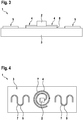
- an electromagnetic transmitting and receiving device 1 according to the invention for a tire is shown schematically.
- the support component 3 is designed as a network.
- the at least one secondary antenna 5 is woven into the carrying component 3.
- the at least one primary antenna 4 follows a spiral shape and the at least one secondary antenna 5 follows a meander shape
- Figure 3 an electromagnetic transmitting and receiving device 1 for a tire according to one embodiment is shown schematically.
- the at least one primary antenna 4 and the at least one storage component 2 are materially connected to the support component 3 by means of an adhesive 6.
- an electromagnetic transmitting and receiving device 1 for a tire is shown schematically.
- the at least one primary antenna 4 and the at least one secondary antenna 5 have a casing 7 made of brass.
- an electromagnetic transmitting and receiving device 1 for a tire according to one embodiment is shown schematically.
- the electromagnetic transmitting and receiving device 1 has a maximum length 8 of 20 mm to 80 mm, a maximum width 9 of 5 mm to 25 mm and a maximum thickness 10 of 1 mm to 2 mm.
- the support component 3 has fibers 11 made of carbon fiber and / or glass fiber.
- an electromagnetic transmitting and receiving device 1 for a tire according to one embodiment is shown schematically.
- the electromagnetic transmitting and receiving device 1 is coated with a rubber material 12 and with an adhesion promoter 13, for example chlorinated polymer, in particular chlorinated polyisoprene and / or chlorinated polybutadiene or chlorinated natural rubber.
- the adhesion promoter 13 lies between the rubber material 12 and the support component 3.
- tire 14 according to the invention is shown schematically in a radial sectional view.
- the tire 14 has a tire inner surface 15 and a tread 16 and can be rotated about an axis of rotation 17 in a direction of rotation 18.
- the tire 14 has at least one electromagnetic transmitting and receiving device 1 according to the invention.
- an electromagnetic transmitting and receiving device 1 between an inner liner 19 of the tire 14 and a carcass 20 of the tire 14, between a carcass 20 of the tire 14 and an apex 21 of the tire 14, between a carcass 20 of the tire 14 and an apex 21 in a ply turning area 22 of the tire 14, between a chipper 23 of the tire 14 and a carcass 20 of the tire 14, between a sidewall 24 of the tire 14 and a carcass 20 of the tire 14, between a rim strip 25 of the tire 14 and a carcass 20 of the tire 14, within a rubber component 26 of the tire 14, between a belt 27 of the tire 14 and a capply 28 of the tire 14, between a capply 28 of the tire 14 and a tread block 29 of the tire 14 and / or in at least one tread block 29 of the Tire 14 be arranged.
- a bead core of the tire 14 is denoted by 30.
- an electromagnetic transmitting and receiving device 1 for a tire according to one embodiment is shown schematically.
- the at least one storage component 2 and the at least one primary antenna 4 are arranged on a support element 31.
- the at least one storage component 2 and / or the at least one primary antenna 4 are in particular materially connected to the support element 31.
- the support element 31 is connected to the support component 3 and arranged thereon.
Landscapes
- Engineering & Computer Science (AREA)
- Microelectronics & Electronic Packaging (AREA)
- Computer Hardware Design (AREA)
- Physics & Mathematics (AREA)
- General Physics & Mathematics (AREA)
- Theoretical Computer Science (AREA)
- Mechanical Engineering (AREA)
- Computer Networks & Wireless Communication (AREA)
- Tires In General (AREA)
Description
- Die Erfindung bezieht sich auf eine elektromagnetische Sende- und Empfangsvorrichtung für einen Reifen sowie auf einen Reifen.
- Die Erfindung geht aus von einer elektromagnetischen Sende- und Empfangsvorrichtung für einen Reifen, aufweisend mindestens eine Speicherkomponente, wobei die mindestens eine Speicherkomponente zur Speicherung einer Reifeninformation vorgesehen ist. Die elektromagnetische Sende- und Empfangsvorrichtung weist eine Tragekomponente auf, wobei die Tragekomponente zum Tragen der mindestens einen Speicherkomponente vorgesehen ist. Die elektromagnetische Sende- und Empfangsvorrichtung weist mindestens eine Primärantenne und mindestens eine Sekundärantenne auf. Die mindestens eine Primärantenne ist zum Senden und zum Empfangen elektromagnetischer Wellen vorgesehen und die mindestens eine Sekundärantenne ist zum Senden und zum Empfangen elektromagnetischer Wellen vorgesehen.
- Das Tragen durch die Tragekomponente bedeutet insbesondere, dass die mindestens eine Speicherkomponente auf der oder an der oder innerhalb der Tragekomponente angeordnet werden kann, wobei die Tragekomponente die mindestens eine Speicherkomponente stützt und sichert.
- Die mindestens eine Primärantenne ist zum Senden und zum Empfangen elektromagnetischer Wellen vorgesehen und die mindestens eine Sekundärantenne ist zum Senden und zum Empfangen elektromagnetischer Wellen vorgesehen.
- Die mindestens eine Primärantenne ist derart mit der mindestens einen Speicherkomponente verbunden, dass eine elektrische Verbindung zwischen der mindestens einen Speicherkomponente und der mindestens einen Primärantenne besteht. Mittels der mindestens einen Primärantenne können Informationen, die in der mindestens einen Speicherkomponente gespeichert sind, mittels elektromagnetischer Wellen durch die mindestens eine Primärantenne versendet werden.
- Die mindestens eine Sendekomponente und die mindestens eine Primärantenne können auch über eine Funkverbindung miteinander verbunden sein.
- Die mindestens eine Sende- und Empfangsvorrichtung ist zum Speichern von Informationen über einen Reifen geeignet. Ferner ist die elektromagnetische Sende- und Empfangsvorrichtung zu einer passiven oder aktiven Auslesung mittels eines externen Lesegerätes geeignet.
- Bei der elektromagnetischen Sende- und Empfangsvorrichtung handelt es sich insbesondere um eine RFID-Vorrichtung. RFID steht für Radio Frequency Identification und bedeutet Identifizierung mit Hilfe elektromagnetischer Wellen.
- Aus dem Stand der Technik sind elektromagnetische Sende- und Empfangsvorrichtungen für Reifen bekannt. Beispielsweise wird in der
EP2223814B1 eine elektromagnetische Sende- und Empfangsvorrichtung offenbart. Die elektromagnetische Sende- und Empfangsvorrichtung wird vor einer Anordnung in einem Reifen zwischen zwei Gummilagen angeordnet. Eine weitere Vorrichtung ist aus derEP 1870262 A2 bekannt. - Bei den aus dem Stand der Technik bekannten elektromagnetischen Sende- und Empfangsvorrichtungen, ist der Einsatz von Primärantennen und von Sekundärantennen bekannt. Dabei wird regelmäßig eine Verbindung über eine Lötstelle zwischen der mindestens einen Primärantenne und der mindestens einen Sekundärantenne geschaffen. Über die Lötstelle können Signale zwischen der Primärantenne und der Sekundärantenne ausgetauscht werden.
- Durch einen Einsatz einer elektromagnetischen Sende- und Empfangsvorrichtung, beispielsweise in einem Reifen, könnte die elektromagnetische Sende- und Empfangsvorrichtung regelmäßig solchen Kräften ausgesetzt werden, die schädigend auf die einzelnen Bestandteile der elektromagnetischen Sende- und Empfangsvorrichtung einwirken könnten. Dabei könnte es beispielsweise zu einem Brechen der Lötstelle, die die Primärantenne mit der Sekundärantenne verbindet, kommen. Ein Bruch dieser Lötstelle könnte die Auslesung von Informationen aus der mindestens einen Speicherkomponente erschweren.
-
WO2016193457 A1 zeigt eine Sende- und Empfangsvorrichtung mit einer Primärantenne und einer Sekundärantenne, die miteinander induktiv verbindbar sind. - Durch den Umstand, wonach die mindestens eine Primärantenne und die mindestens eine Sekundärantenne miteinander induktiv verbindbar sind, kann ein Signalaustausch auf Grundlage der elektromagnetischen Induktion genutzt werden. Der elektromagnetischen Induktion liegt die Nutzung elektromagnetischer Felder zu Grunde. Elektromagnetische Felder sind gegenüber mechanischen Belastungen unempfindlich. Die Einsatzfähigkeit der elektromagnetischen Sende- und Empfangsvorrichtung wird also sichergestellt. Schließlich wird eine Anzahl von Komponenten der elektromagnetischen Sende- und Empfangsvorrichtung, die unter einer mechanischen Belastung Schaden nehmen könnten, verringert.
- Die mindestens eine Primärantenne und die mindestens eine Sekundärantenne sind derart miteinander verbunden, dass elektromagnetische Wellen, die von der mindestens einen Primärantenne ausgesendet werden, durch die mindestens einen Sekundärantenne empfangen und, beispielsweise nach Änderung einer Frequenz der elektromagnetischen Wellen und/oder einer Modulation der elektromagnetischen Wellen, von der mindestens einen Sekundärantenne ausgesendet werden.
- Die mindestens eine Sekundärantenne nimmt die von der mindestens einen Primärantenne ausgesendeten elektromagnetischen Wellen auf, verwandelt diese elektromagnetischen Wellen und sendet diese verwandelten elektromagnetischen Wellen aus.
- Die mindestens eine Primärantenne und die mindestens eine Sekundärantenne sind ferner insbesondere derart miteinander verbunden, dass elektromagnetische Wellen, die durch die mindestens einen Sekundärantenne empfangen werden, von der mindestens einen Sekundärantenne verändert werden, beispielsweise durch Änderung der Frequenz oder durch eine Modulation, und dann an die mindestens eine Primärantenne übertragen werden.
- Die mindestens eine Primärantenne nimmt die von der mindestens einen Sekundärantenne ausgesendeten elektromagnetischen Wellen auf, verwandelt diese elektromagnetischen Wellen und gibt, der verwandelten elektromagnetischen Welle entsprechende, elektrische Signale an die mindestens eine Speicherkomponente weiter. Einer Induktion liegen veränderliche elektrische Ströme und elektrische Wechselfelder zu Grunde.
- Erfindungsgemäß ist die Tragekomponente zumindest teilweise oder vollständig als ein Netz oder ein Gitter ausgebildet. Die mindestens eine Primärantenne ist dabei in die Tragekomponente eingewoben und/oder die mindestens eine Sekundärantenne ist in die Tragekomponente eingewoben. Die Tragekomponente ist insbesondere dann als gewebtes Netz oder gewebtes Gitter ausgebildet, wenn die Tragekomponente aus Filamenten ausgebildet ist, die ein Netz oder die ein Gitter ausbilden.
- Die Erfindung betrifft ferner einen Reifen. Der Reifen weist eine Reifeninnenfläche und einen Laufstreifen auf. Der Reifen ist um eine Rotationsachse in eine Umlaufrichtung rotierbar. Der Reifen weist mindestens eine erfindungsgemäße elektromagnetische Sende- und Empfangsvorrichtung auf.
- Bei dem Reifen handelt es sich insbesondere um einen Lkw-Reifen, um einen Pkw-Reifen oder um einen Fahrrad-Reifen oder um einen Motorrad-Reifen.
- Bei der Reifeninformation handelt es sich insbesondere um eine Information über eine Reifenklasse, über ein Produktionsdatum des Reifens oder über eine andere technische Eigenschaft des Reifens oder um eine eindeutige Nummer zur Identifizierung des Reifens.
- Weitere vorteilhafte Ausgestaltungsformen der vorliegenden Erfindung sind Gegenstand der Unteransprüche.
- Eine Anzahl an Primärantennen kann zwei betragen und eine Anzahl an Sekundärantennen kann zwei betragen. Dabei können die Primärantennen und die Sekundärantennen an verschiedenen Seiten oder Oberflächen der Tragekomponenten angeordnet sein.
- Gemäß einer nächsten vorzugsweisen Ausführungsform der Erfindung ist die Tragekomponente teilweise oder vollständig aus einem Gummimaterial, insbesondere Naturkautschuk, Butylkautschuk, synthetischer Kautschuk, Styrol-Butadien-Kautschuk, Polybutadien-Kautschuk, Nitrilkautschuk, Chloropren-Kautschuk und/oder Ethylen-Propylen-Dien-Kautschuk, und/oder einem Polyamid und/oder einem Elastomer und/oder einem Epoxidharz ausgebildet.
- Durch den erfindungsgemäßen Umstand, wonach die Tragekomponente teilweise oder vollständig aus einem Gummimaterial, insbesondere Naturkautschuk, Butylkautschuk, synthetischer Kautschuk, Styrol-Butadien-Kautschuk, Polybutadien-Kautschuk, Nitrilkautschuk, Chloropren-Kautschuk und/oder Ethylen-Propylen-Dien-Kautschuk, und/oder einem Polyamid und/oder einem Elastomer und/oder einem Epoxidharz ausgebildet ist, wird eine Tragekomponente bereitgestellt, die eine ausreichende mechanische Stabilität aufweist.
- Gemäß einer vorteilhaften Ausgestaltungsform der Erfindung folgt die Tragekomponente einer Form eines Ovals oder eines Kreises oder eines Dreiecks oder eines Vierecks.
- Insbesondere kann die Tragkomponente abgerundete Ecken aufweisen, wobei die Rundungen der Ecken jeweils einem Kreisbogen eines Kreises mit einem Radius der größer als 1 mm ist folgen.
- Ferner kann die Tragekomponente Öffnungen aufweisen die durch die Tragekomponente vollständig hindurch reichen. Durch diese Öffnungen kann eine verbesserte Anbindung an eine Gummiumgebung, insbesondere während eines Vulkanisationsvorgangs, erreicht werden. Diese Öffnungen weisen insbesondere einen kreisförmigen Querschnitt mit einem Durchmesser von beispielsweise 1 mm bis 5 mm auf.
- Gemäß einer nächsten vorzugsweisen Ausführungsform der Erfindung ist die mindestens eine Primärantenne aus Kupfer, Aluminium, Silber, Eisen, Zink, Zinn, einem elektrisch leitfähigem Kunststoff, beispielsweise Polyacetylene, Poly(p-Phenylen Vinylen), Polyfluoren, Polyphenylen, Polypyren, Polyazulen, Polyamid, Polynaphthalen, Polypyrrol, Polycarbazol, Polyindol, Polythiophen, Poly(3,4-ethylenedioxythiophen), Poly(p-Phenylen Sulfide), und/oder einem elektrisch leitfähigem Elastomer, beispielsweise einem Naturkautschuk oder einem Kautschuk der Kohlenstoffpartikel aufweist oder einem Kautschuk der Ruße aufweist oder einem Kautschuk der Metallpartikel aufweist, ausgebildet.
- Alternativ oder zusätzlich ist die mindestens eine Sekundärantenne aus Kupfer, Aluminium, Silber, Eisen, Zink, Zinn, einem elektrisch leitfähigem Kunststoff, beispielsweise Polyacetylene, Poly(p-Phenylen Vinylen), Polyfluoren, Polyphenylen, Polypyren, Polyazulen, Polyamid, Polynaphthalen, Polypyrrol, Polycarbazol, Polyindol, Polythiophen, Poly(3,4-ethylenedioxythiophen), Poly(p-Phenylen Sulfide), und/oder einem elektrisch leitfähigem Elastomer, beispielsweise einem Naturkautschuk oder einem Kautschuk der Kohlenstoffpartikel aufweist oder einem Kautschuk der Ruße aufweist oder einem Kautschuk der Metallpartikel aufweist, ausgebildet.
- Gemäß einer nächsten vorzugsweisen Ausführungsform der Erfindung ist die mindestens eine Primärantenne mittels eines Klebemittels stoffschlüssig mit der Tragekomponente verbunden und/oder die mindestens eine Sekundärantenne ist mittels eines Klebemittels stoffschlüssig mit der Tragekomponente verbunden und/oder die mindestens eine Speicherkomponente ist mittels eines Klebemittels stoffschlüssig mit der Tragekomponente verbunden.
- Gemäß einer nächsten vorzugsweisen Ausführungsform der Erfindung weist die mindestens eine Primärantenne eine Ummantelung aus Messing auf und/oder die mindestens eine Sekundärantenne weist eine Ummantelung aus Messing auf.
- Durch den erfindungsgemäßen Umstand, wonach die mindestens eine Primärantenne eine Ummantelung aus Messing aufweist und/oder die mindestens eine Sekundärantenne eine Ummantelung aus Messing aufweist, wird eine verbesserte Anbindung der mindestens einen Primärantenne und/oder der mindestens einen Sekundärantenne an eine Gummiumgebung erreicht. Bei der Gummiumgebung handelt es sich beispielsweise um den Bereich eines Reifens in den die elektromagnetische Sende- und Empfangsvorrichtung integriert ist.
- Gemäß einer nächsten vorzugsweisen Ausführungsform der Erfindung folgt die mindestens eine Primärantenne einer Wellenform oder Mäanderform oder einer Spiralform oder einer Helixform oder einer Federform und/oder die mindestens eine Sekundärantenne folgt einer Wellenform oder Mäanderform oder einer Spiralform oder einer Helixform oder einer Federform.
- Durch den erfindungsgemäßen Umstand, wonach die mindestens eine Primärantenne einer Wellenform oder Mäanderform oder einer Spiralform oder einer Helixform oder einer Federform folgt und/oder die mindestens eine Sekundärantenne einer Wellenform oder Mäanderform oder einer Spiralform oder einer Helixform oder einer Federform folgt, wird eine verbesserte mechanische Dehnbarkeit der mindestens einen Primärantenne und der mindestens einen Sekundärantenne sichergestellt. Somit können die mindestens eine Primärantenne und die mindestens eine Sekundärantenne mechanischen Belastungen besser standhalten.
- Gemäß einer nächsten vorzugsweisen Ausführungsform der Erfindung weist die elektromagnetische Sende- und Empfangsvorrichtung eine Maximallänge von 20 mm bis 80 mm, eine Maximalbreite von 5 mm bis 25 mm und/oder eine Maximaldicke von 1 mm bis 2 mm auf.
- Insbesondere kann ein Betrag der Maximalbreite 50 % des Betrags der Maximallänge betragen und/oder ein Betrag der Maximaldicke kann insbesondere 1% bis 5 % des Betrags der Maximallänge betragen.
- Ein Körper, wie die elektromagnetische Sende- und Empfangsvorrichtung, weist grundsätzlich Längen, Breiten und Dicken auf, wobei es sich dabei um räumliche Erstreckungen der elektromagnetischen Sende- und Empfangsvorrichtung handelt, wobei diese Erstreckungen zueinander jeweils in einem rechten Winkel stehen.
- Gemäß einer nächsten vorzugsweisen Ausführungsform der Erfindung weist die Tragekomponente Fasern aus Kohlenstoff und/oder Glas auf. Fasern aus Kohlenstoff werden auch als Kohlenstofffasern oder Kohlefasern bezeichnet. Fasern aus Glas werden auch als Glasfasern bezeichnet.
- Durch den erfindungsgemäßen Umstand, wonach die die Tragekomponente Fasern aus Kohlenstoff und/oder Glas aufweist, wird der Einsatz der Tragekomponente weiter sichergestellt. Hintergrund dieser Sicherstellung des Einsatzes der Tragekomponente ist der Umstand, dass die Kohlefasern und/oder Glasfasern die Tragekomponente mechanisch weiter stabilisieren.
- Gemäß einer nächsten vorzugsweisen Ausführungsform der Erfindung ist die elektromagnetische Sende- und Empfangsvorrichtung mit einem Gummimaterial und/oder mit einem Haftvermittler beschichtet. Bei dem Haftvermittler handelt es sich beispielsweise um ein chloriertes Polymer, insbesondere chloriertes Polyisopren und/oder chloriertes Polybutadien oder chlorierten Naturkautschuk.
- Gemäß einer nächsten vorzugsweisen Ausführungsform der Erfindung sind die mindestens eine Speicherkomponente und/oder die mindestens eine Primärantenne auf einem Tragelement angeordnet. Die mindestens eine Speicherkomponente und/oder die mindestens eine Primärantenne sind insbesondere stoffschlüssig mit dem Trageelement verbunden.
- Das Trageelement ist mit der Tragekomponente verbunden, insbesondere stoffschlüssig, kraftschlüssig oder formschlüssig, und insbesondere ist das Trageelement auf der Tragekomponente angeordnet.
- Gemäß einer nächsten vorzugsweisen Ausführungsform der Erfindung ist das Trageelement teilweise oder vollständig aus einem Gummimaterial, insbesondere Naturkautschuk, Butylkautschuk, synthetischer Kautschuk, Styrol-Butadien-Kautschuk, Polybutadien-Kautschuk, Nitrilkautschuk, Chloropren-Kautschuk und/oder Ethylen-Propylen-Dien-Kautschuk, und/oder einem Polyamid und/oder einem Elastomer und/oder einem Epoxidharz ausgebildet.
- Gemäß einer nächsten vorzugsweisen Ausführungsform der Erfindung weist das Trageelement Fasern aus Kohlenstoff und/oder Glas auf.
- Gemäß einer nächsten vorzugsweisen Ausführungsform des erfindungsgemäßen Reifens ist mindestens eine elektromagnetische Sende- und Empfangsvorrichtung zwischen einem Innerliner des Reifens und einer Karkasse des Reifens, zwischen einer Karkasse des Reifens und einem Apex des Reifens, zwischen einer Karkasse des Reifens und einem Apex in einem Lagenumschlagsbereich des Reifens, zwischen einem Wulstverstärker des Reifens und einer Karkasse des Reifens, zwischen einer Seitenwand des Reifens und einer Karkasse des Reifens, zwischen einem Rimstrip des Reifens und einer Karkasse des Reifens, innerhalb eines Gummibauteils des Reifens, zwischen einem Gürtel des Reifens und einem Capply des Reifens, zwischen einem Capply des Reifens und einem Profilblock des Reifens und/oder in mindestens einem Profilblock des Reifens angeordnet.
- Weitere Merkmale, Vorteile und Einzelheiten, auf die die Erfindung in ihrem Umfang aber nicht beschränkt ist, werden nun anhand der Zeichnungen näher beschrieben.
- Es zeigt:
-
Fig. 1 : Eine schematische Darstellung einer erfindungsgemäßen elektromagnetischen Sende- und Empfangsvorrichtung; -
Fig. 2 : eine schematische Darstellung einer erfindungsgemäßen elektromagnetischen Sende- und Empfangsvorrichtung gemäß einer Ausführungsform; -
Fig. 3 : eine schematische Darstellung einer erfindungsgemäßen elektromagnetischen Sende- und Empfangsvorrichtung gemäß einer Ausführungsform; -
Fig. 4 : eine schematische Darstellung einer erfindungsgemäßen elektromagnetischen Sende- und Empfangsvorrichtung gemäß einer Ausführungsform; -
Fig. 5 : eine schematische Darstellung einer erfindungsgemäßen elektromagnetischen Sende- und Empfangsvorrichtung gemäß einer Ausführungsform; -
Fig. 6 : eine schematische Darstellung einer erfindungsgemäßen elektromagnetischen Sende- und Empfangsvorrichtung gemäß einer Ausführungsform; -
Fig. 7 : eine schematische Darstellung eines erfindungsgemäßen Reifens; -
Fig. 8 : eine schematische Darstellung einer erfindungsgemäßen elektromagnetischen Sende- und Empfangsvorrichtung gemäß einer Ausführungsform. - In der
Figur 1 ist eine elektromagnetische Sende- und Empfangsvorrichtung 1 für einen Reifen schematisch dargestellt. Die elektromagnetische Sende- und Empfangsvorrichtung 1 weist mindestens eine Speicherkomponente 2 auf. Die mindestens eine Speicherkomponente 2 ist zur Speicherung einer Reifeninformation vorgesehen. Die elektromagnetische Sende- und Empfangsvorrichtung 1 weist eine Tragekomponente 3 auf. Die Tragekomponente 3 ist zum Tragen der mindestens einen Speicherkomponente 2 vorgesehen. - Die elektromagnetische Sende- und Empfangsvorrichtung 1 weist ferner mindestens eine Primärantenne 4 und mindestens eine Sekundärantenne 5 auf.
- Die mindestens eine Primärantenne 4 ist zum Senden und zum Empfangen elektromagnetischer Wellen vorgesehen. Die mindestens eine Sekundärantenne 5 ist zum Senden und zum Empfangen elektromagnetischer Wellen vorgesehen.
- Die mindestens eine Primärantenne 4 ist mit der mindestens einen Speicherkomponente 2 verbunden und kann zum Versenden von Informationen, die in der mindestens einen Speicherkomponente 2 gespeichert sind verwendet werden.
- Ebenso können Informationen, die über elektromagneteiche Wellen transportiert werden, mittels der Primärantenne 4 durch den Empfang der der elektromagnetischen Wellen an die mindestens eine Speicherkomponente 2 übertragen und auf dieser gespeichert werden.
- Die mindestens eine Primärantenne 4 und die mindestens eine Sekundärantenne 5 sind miteinander induktiv verbindbar.
- Gemäß der Darstellung in der
Figur 1 weist die elektromagnetische Sende- und Empfangsvorrichtung 1 zwei Sekundärantennen 5 auf. - In der
Figur 2 ist eine erfindungsgemäße elektromagnetische Sende- und Empfangsvorrichtung 1 für einen Reifen schematisch dargestellt. Gemäß der Darstellung in derFigur 2 ist die Tragekomponente 3 als ein Netz ausgebildet. Die mindestens eine Sekundärantenne 5 ist in die Tragekomponente 3 eingewoben. - Gemäß der Darstellung in der
Figur 2 folgt die mindestens eine Primärantenne 4 einer Spiralform und die mindestens eine Sekundärantenne 5 folgt einer Mäanderform In derFigur 3 ist eine elektromagnetische Sende- und Empfangsvorrichtung 1 für einen Reifen gemäß einer Ausführungsform schematisch dargestellt. Gemäß der Darstellung in derFigur 3 sind die mindestens eine Primärantenne 4 und die mindestens eine Speicherkomponente 2 mittels eines Klebemittels 6 stoffschlüssig mit der Tragekomponente 3 verbunden. - In der
Figur 4 ist eine elektromagnetische Sende- und Empfangsvorrichtung 1 für einen Reifen gemäß einer Ausführungsform schematisch dargestellt. Gemäß der Darstellung in derFigur 4 weisen die mindestens eine Primärantenne 4 und die mindestens eine Sekundärantenne 5 eine Ummantelung 7 aus Messing auf. - In der
Figur 5 ist eine elektromagnetische Sende- und Empfangsvorrichtung 1 für einen Reifen gemäß einer Ausführungsform schematisch dargestellt. Gemäß der Darstellung in derFigur 5 weist die elektromagnetische Sende- und Empfangsvorrichtung 1 eine Maximallänge 8 von 20 mm bis 80 mm, eine Maximalbreite 9 von 5 mm bis 25 mm und eine Maximaldicke 10 von 1 mm bis 2 mm auf. - Insbesondere weist die die Tragekomponente 3 Fasern 11 aus Kohlefaser und/oder Glasfaser auf.
- In der
Figur 6 ist eine elektromagnetische Sende- und Empfangsvorrichtung 1 für einen Reifen gemäß einer Ausführungsform schematisch dargestellt. Gemäß der Darstellung in derFigur 6 ist die elektromagnetische Sende- und Empfangsvorrichtung 1 mit einem Gummimaterial 12 und mit einem Haftvermittler 13, beispielsweise chloriertes Polymer, insbesondere chloriertes Polyisopren und/oder chloriertes Polybutadien oder chlorierter Naturkautschuk, beschichtet. Der Haftvermittler 13 liegt zwischen dem Gummimaterial 12 und der Tragekomponente 3. - In der
Figur 7 ist erfindungsgemäßer Reifen 14 in Radialschnittansicht schematisch dargestellt. Der Reifen 14 weist eine Reifeninnenfläche 15 und einen Laufstreifen 16 auf und ist um eine Rotationsachse 17 in eine Umlaufrichtung 18 rotierbar. Der Reifen 14 weist mindestens eine erfindungsgemäße elektromagnetische Sende- und Empfangsvorrichtung 1 auf. - Insbesondere kann eine erfindungsgemäße elektromagnetische Sende- und Empfangsvorrichtung 1 zwischen einem Innerliner 19 des Reifens 14 und einer Karkasse 20 des Reifens 14, zwischen einer Karkasse 20 des Reifens 14 und einem Apex 21 des Reifens 14, zwischen einer Karkasse 20 des Reifens 14 und einem Apex 21 in einem Lagenumschlagsbereich 22 des Reifens 14, zwischen einem Wulstverstärker 23 des Reifens 14 und einer Karkasse 20 des Reifens 14, zwischen einer Seitenwand 24 des Reifens 14 und einer Karkasse 20 des Reifens 14, zwischen einem Rimstrip 25 des Reifens 14 und einer Karkasse 20 des Reifens 14, innerhalb eines Gummibauteils 26 des Reifens 14, zwischen einem Gürtel 27 des Reifens 14 und einem Capply 28 des Reifens 14, zwischen einem Capply 28 des Reifens 14 und einem Profilblock 29 des Reifens 14 und/oder in mindestens einem Profilblock 29 des Reifens 14 angeordnet sein. Ein Wulstkern des Reifens 14 wird mit 30 bezeichnet.
- In der
Figur 8 ist eine elektromagnetische Sende- und Empfangsvorrichtung 1 für einen Reifen gemäß einer Ausführungsform schematisch dargestellt. Gemäß der Darstellung in derFigur 8 sind die mindestens eine Speicherkomponente 2 und die mindestens eine Primärantenne 4 auf einem Tragelement 31 angeordnet. - Die mindestens eine Speicherkomponente 2 und/oder die mindestens eine Primärantenne 4 sind insbesondere stoffschlüssig mit dem Trageelement 31 verbunden.
- Das Trageelement 31 mit der Tragekomponente 3 verbunden und auf dieser angeordnet.
-
- 1
- Elektromagnetische Sende- und Empfangsvorrichtung
- 2
- Speicherkomponente
- 3
- Tragekomponente
- 4
- Primärantenne
- 5
- Sekundärantenne
- 6
- Klebemittel
- 7
- Ummantelung
- 8
- Maximallänge
- 9
- Maximalbreite
- 10
- Maximaldicke
- 11
- Fasern
- 12
- Gummischicht
- 13
- Haftvermittler
- 14
- Reifen
- 15
- Reifeninnenfläche
- 16
- Laufstreifen
- 17
- Rotationsachse
- 18
- Umlaufrichtung
- 19
- Innerliner
- 20
- Karkasse
- 21
- Apex
- 22
- Lagenumschlagsbereich
- 23
- Wulstverstärker
- 24
- Seitendwand
- 25
- Rimstrip
- 26
- Beliebiges Gummibauteil
- 27
- Gürtel
- 28
- Capply
- 29
- Profilblock
- 30
- Wulstkern
- 31
- Trageelement
Claims (11)
- Elektromagnetische Sende- und Empfangsvorrichtung (1) für einen Reifen (14), aufweisend mindestens eine Speicherkomponente (2), wobei die mindestens eine Speicherkomponente (2) zur Speicherung einer Reifeninformation vorgesehen ist, aufweisend eine Tragekomponente (3), wobei die Tragekomponente (3) zum Tragen der mindestens einen Speicherkomponente (2) vorgesehen ist, wobei die elektromagnetische Sende- und Empfangsvorrichtung (1) mindestens eine Primärantenne (4) und mindestens eine Sekundärantenne (5) aufweist, wobei die mindestens eine Primärantenne (4) zum Senden und zum Empfangen elektromagnetischer Wellen vorgesehen ist und die mindestens eine Sekundärantenne (5) zum Senden und zum Empfangen elektromagnetischer Wellen vorgesehen ist, wobei die mindestens eine Primärantenne (4) und die mindestens eine Sekundärantenne (5) miteinander induktiv verbindbar sind, dadurch gekennzeichnet, dass die Tragekomponente (3) zumindest teilweise oder vollständig als ein Netz oder ein Gitter ausgebildet ist, wobei die mindestens eine Primärantenne (4) in die Tragekomponente (3) eingewoben ist und/oder die mindestens eine Sekundärantenne (5) in die Tragekomponente (3) eingewoben ist.
- Elektromagnetische Sende- und Empfangsvorrichtung (1) nach Anspruch 1, dadurch gekennzeichnet, dass die Tragekomponente (3) teilweise oder vollständig aus einem Gummimaterial, insbesondere Naturkautschuk, Butylkautschuk, synthetischer Kautschuk, Styrol-Butadien-Kautschuk, Polybutadien-Kautschuk, Nitrilkautschuk, Chloropren-Kautschuk und/oder Ethylen-Propylen-Dien-Kautschuk, und/oder einem Polyamid und/oder einem Elastomer und/oder einem Epoxidharz ausgebildet ist.
- Elektromagnetische Sende- und Empfangsvorrichtung (1) nach einem der vorhergehenden Ansprüche, dadurch gekennzeichnet, dass die mindestens eine Primärantenne (4) aus Kupfer, Aluminium, Silber, Eisen, Zink, Zinn, einem elektrisch leitfähigem Kunststoff, beispielsweise Polyacetylene, Poly(p-Phenylen Vinylen), Polyfluoren, Polyphenylen, Polypyren, Polyazulen, Polyamid, Polynaphthalen, Polypyrrol, Polycarbazol, Polyindol, Polythiophen, Poly(3,4-ethylenedioxythiophen), Poly(p-Phenylen Sulfide), und/oder einem elektrisch leitfähigem Elastomer, beispielsweise einem Naturkautschuk oder einem Kautschuk der Kohlenstoffpartikel aufweist oder einem Kautschuk der Ruße aufweist oder einem Kautschuk der Metallpartikel aufweist, ausgebildet ist und/oder die mindestens eine Sekundärantenne (5) aus Kupfer, Aluminium, Silber, Eisen, Zink, Zinn, einem elektrisch leitfähigem Kunststoff, beispielsweise Polyacetylene, Poly(p-Phenylen Vinylen), Polyfluoren, Polyphenylen, Polypyren, Polyazulen, Polyamid, Polynaphthalen, Polypyrrol, Polycarbazol, Polyindol, Polythiophen, Poly(3,4-ethylenedioxythiophen), Poly(p-Phenylen Sulfide), und/oder einem elektrisch leitfähigem Elastomer, beispielsweise einem Naturkautschuk oder einem Kautschuk der Kohlenstoffpartikel aufweist oder einem Kautschuk der Ruße aufweist oder einem Kautschuk der Metallpartikel aufweist, ausgebildet ist.
- Elektromagnetische Sende- und Empfangsvorrichtung (1) nach einem der vorhergehenden Ansprüche, dadurch gekennzeichnet, dass die mindestens eine Primärantenne (4) mittels eines Klebemittels (6) stoffschlüssig mit der Tragekomponente (3) verbunden ist und/oder die mindestens eine Sekundärantenne (5) mittels eines Klebemittels (6) stoffschlüssig mit der Tragekomponente (3) verbunden ist und/oder die mindestens eine Speicherkomponente (2) mittels eines Klebemittels (6) stoffschlüssig mit der Tragekomponente (3) verbunden ist.
- Elektromagnetische Sende- und Empfangsvorrichtung (1) nach einem der vorhergehenden Ansprüche, dadurch gekennzeichnet, dass die mindestens eine Primärantenne (4) eine Ummantelung (7) aus Messing aufweist und/oder die mindestens eine Sekundärantenne (5) eine Ummantelung (7) aus Messing aufweist.
- Elektromagnetische Sende- und Empfangsvorrichtung (1) nach einem der vorhergehenden Ansprüche, dadurch gekennzeichnet, dass die mindestens eine Primärantenne (4) einer Wellenform oder einer Mäanderform oder einer Spiralform oder einer Helixform oder einer Federform folgt und/oder die mindestens eine Sekundärantenne (5) einer Wellenform oder einer Mäanderform oder einer Spiralform oder einer Helixform oder einer Federform folgt.
- Elektromagnetische Sende- und Empfangsvorrichtung (1) nach einem der vorhergehenden Ansprüche, dadurch gekennzeichnet, dass die elektromagnetische Sende- und Empfangsvorrichtung (1) eine Maximallänge (8) von 20 mm bis 80 mm, eine Maximalbreite (9) von 5 mm bis 25 mm und/oder eine Maximaldicke (10) von 1 mm bis 2 mm aufweist.
- Elektromagnetische Sende- und Empfangsvorrichtung (1) nach einem der vorhergehenden Ansprüche, dadurch gekennzeichnet, dass die Tragekomponente (3) Fasern (11) aus Kohlenstoff und/oder Glas aufweist.
- Elektromagnetische Sende- und Empfangsvorrichtung (1) nach einem der vorhergehenden Ansprüche, dadurch gekennzeichnet, dass die elektromagnetische Sende- und Empfangsvorrichtung (1) mit einem Gummimaterial (12) und/oder mit einem Haftvermittler (13), beispielsweise chloriertes Polymer, insbesondere chloriertes Polyisopren und/oder chloriertes Polybutadien oder chlorierter Naturkautschuk, beschichtet ist.
- Elektromagnetische Sende- und Empfangsvorrichtung (1) nach einem der vorhergehenden Ansprüche, dadurch gekennzeichnet, dass die mindestens eine Speicherkomponente (2) und/oder die mindestens eine Primärantenne (4) auf einem Tragelement (31) angeordnet sind, wobei die mindestens eine Speicherkomponente (2) und/oder die mindestens eine Primärantenne (4) insbesondere stoffschlüssig mit dem Trageelement (31) verbunden sind, und das Trageelement (31) mit der Tragekomponente (3) verbunden ist.
- Reifen (14), aufweisend eine Reifeninnenfläche (15) und einen Laufstreifen (16), wobei der Reifen (14) um eine Rotationsachse (17) in eine Umlaufrichtung (18) rotierbar ist, dadurch gekennzeichnet, dass der Reifen (14) mindestens eine elektromagnetische Sende- und Empfangsvorrichtung (1) nach einem der vorgehenden Ansprüche aufweist.
Applications Claiming Priority (1)
| Application Number | Priority Date | Filing Date | Title |
|---|---|---|---|
| DE102018209154.4A DE102018209154A1 (de) | 2018-06-08 | 2018-06-08 | Elektromagnetische Sende- und Empfangsvorrichtung |
Publications (2)
| Publication Number | Publication Date |
|---|---|
| EP3578395A1 EP3578395A1 (de) | 2019-12-11 |
| EP3578395B1 true EP3578395B1 (de) | 2021-08-25 |
Family
ID=66379718
Family Applications (1)
| Application Number | Title | Priority Date | Filing Date |
|---|---|---|---|
| EP19172156.2A Active EP3578395B1 (de) | 2018-06-08 | 2019-05-02 | Elektromagnetische sende- und empfangsvorrichtung |
Country Status (2)
| Country | Link |
|---|---|
| EP (1) | EP3578395B1 (de) |
| DE (1) | DE102018209154A1 (de) |
Cited By (1)
| Publication number | Priority date | Publication date | Assignee | Title |
|---|---|---|---|---|
| EP4711308A1 (de) * | 2024-09-11 | 2026-03-18 | Ammega Group AG | Riemen mit einer vorrichtung zur hochfrequenzkommunikation mit hoher zuverlässigkeit |
Families Citing this family (4)
| Publication number | Priority date | Publication date | Assignee | Title |
|---|---|---|---|---|
| CH717620A9 (de) | 2020-07-07 | 2022-02-28 | Daetwyler Schweiz Ag | Fluidüberwachungssystem zum Überwachen eines Vorliegens oder eines Zustands eines Fluids unter Verwendung seiner Permittivität und das Verfahren dazu. |
| EP4179465B1 (de) | 2020-07-07 | 2024-05-15 | Dätwyler Schweiz AG | Elastomeres sensorbauelement mit integriertem sensormodul |
| JP7526141B2 (ja) * | 2021-06-30 | 2024-07-31 | 株式会社ブリヂストン | タイヤ |
| IT202200003290A1 (it) * | 2022-02-22 | 2023-08-22 | Pearfid Soc A Responsabilita Limitata Semplificata | Metodo di realizzazione di dispositivi a radiofrequenza |
Citations (1)
| Publication number | Priority date | Publication date | Assignee | Title |
|---|---|---|---|---|
| EP1870262A2 (de) * | 2006-05-30 | 2007-12-26 | The Goodyear Tire & Rubber Company | Transponderträger für einen Reifen |
Family Cites Families (7)
| Publication number | Priority date | Publication date | Assignee | Title |
|---|---|---|---|---|
| JP4397533B2 (ja) * | 2001-01-15 | 2010-01-13 | 横浜ゴム株式会社 | タイヤ用トランスポンダ |
| DE10217215C5 (de) * | 2002-04-18 | 2012-04-19 | Continental Reifen Deutschland Gmbh | Einrichtung zur Überwachung und Identifizierung von Luftreifen |
| US20040159383A1 (en) * | 2002-06-11 | 2004-08-19 | Adamson John David | Method for embedding a radio frequency antenna in a tire, and an antenna for embedding in a tire |
| DE102007043077A1 (de) * | 2007-09-10 | 2009-03-12 | Robert Bosch Gmbh | Sensoranordnung und Verfahren zum Betrieb einer Sensoranordnung |
| US8430142B2 (en) | 2009-02-25 | 2013-04-30 | The Goodyear Tire & Rubber Company | Environmentally resistant assembly containing an electronic device for use in a tire |
| FR3037200B1 (fr) * | 2015-06-03 | 2017-05-26 | Michelin & Cie | Transpondeur radiofrequence pour pneumatique |
| DE102018114616A1 (de) * | 2017-06-20 | 2018-12-20 | Turck Holding Gmbh | Gummireifen mit Transponderanordnung |
-
2018
- 2018-06-08 DE DE102018209154.4A patent/DE102018209154A1/de not_active Withdrawn
-
2019
- 2019-05-02 EP EP19172156.2A patent/EP3578395B1/de active Active
Patent Citations (1)
| Publication number | Priority date | Publication date | Assignee | Title |
|---|---|---|---|---|
| EP1870262A2 (de) * | 2006-05-30 | 2007-12-26 | The Goodyear Tire & Rubber Company | Transponderträger für einen Reifen |
Cited By (1)
| Publication number | Priority date | Publication date | Assignee | Title |
|---|---|---|---|---|
| EP4711308A1 (de) * | 2024-09-11 | 2026-03-18 | Ammega Group AG | Riemen mit einer vorrichtung zur hochfrequenzkommunikation mit hoher zuverlässigkeit |
Also Published As
| Publication number | Publication date |
|---|---|
| DE102018209154A1 (de) | 2019-12-12 |
| EP3578395A1 (de) | 2019-12-11 |
Similar Documents
| Publication | Publication Date | Title |
|---|---|---|
| EP3578395B1 (de) | Elektromagnetische sende- und empfangsvorrichtung | |
| DE60310957T2 (de) | Rfid-reifengürtelantennensystem und verfahren | |
| DE60320037T2 (de) | Anordnung und verfahren zur drahtlosen kommunikation | |
| US7492328B2 (en) | Composite antenna for a tire | |
| DE112018007758T5 (de) | Luftreifen und Montageflächengebilde | |
| DE102012012860A1 (de) | Bereitstellen einer Assoziationsverbindung | |
| WO2020108833A1 (de) | Fahrzeugreifen | |
| DE19915999C2 (de) | Kraftfahrzeug mit Reifendruckkontrollsystem | |
| EP3760456A1 (de) | Reifen | |
| DE102019215069A1 (de) | Reifen | |
| WO2018224193A1 (de) | Elektromagnetische sende- und empfangsvorrichtung für einen reifen | |
| DE102006042346A1 (de) | Medizinische Vorrichtung mit einer Radiofrequenzerfassungsvorrichtung | |
| WO2009100729A1 (de) | Identifikationsmarke zur identifikation von objekten mit metallischer oberfläche | |
| DE102018209160A1 (de) | Elektromagnetische Sende- und Empfangsvorrichtung | |
| CN101168344A (zh) | 轮胎内部rfid标签的安装结构 | |
| EP3739519B1 (de) | Reifen | |
| DE10217215C5 (de) | Einrichtung zur Überwachung und Identifizierung von Luftreifen | |
| EP3969297B1 (de) | Reifen | |
| EP3953189B1 (de) | Reifen | |
| DE102018200104A1 (de) | Sicherheitssystem | |
| EP2466554B1 (de) | Mobiler ID-Geber für Keyless-Systeme | |
| EP3808577B1 (de) | Reifen | |
| DE102021203138A1 (de) | Reifen | |
| DE102019207021A1 (de) | Reifen | |
| DE102007028357A1 (de) | Transponderkarte |
Legal Events
| Date | Code | Title | Description |
|---|---|---|---|
| PUAI | Public reference made under article 153(3) epc to a published international application that has entered the european phase |
Free format text: ORIGINAL CODE: 0009012 |
|
| STAA | Information on the status of an ep patent application or granted ep patent |
Free format text: STATUS: THE APPLICATION HAS BEEN PUBLISHED |
|
| AK | Designated contracting states |
Kind code of ref document: A1 Designated state(s): AL AT BE BG CH CY CZ DE DK EE ES FI FR GB GR HR HU IE IS IT LI LT LU LV MC MK MT NL NO PL PT RO RS SE SI SK SM TR |
|
| AX | Request for extension of the european patent |
Extension state: BA ME |
|
| STAA | Information on the status of an ep patent application or granted ep patent |
Free format text: STATUS: REQUEST FOR EXAMINATION WAS MADE |
|
| 17P | Request for examination filed |
Effective date: 20200612 |
|
| RBV | Designated contracting states (corrected) |
Designated state(s): AL AT BE BG CH CY CZ DE DK EE ES FI FR GB GR HR HU IE IS IT LI LT LU LV MC MK MT NL NO PL PT RO RS SE SI SK SM TR |
|
| RAP1 | Party data changed (applicant data changed or rights of an application transferred) |
Owner name: CONTINENTAL REIFEN DEUTSCHLAND GMBH |
|
| RIC1 | Information provided on ipc code assigned before grant |
Ipc: H01Q 9/27 20060101ALI20210122BHEP Ipc: G06K 19/077 20060101ALI20210122BHEP Ipc: H01Q 1/22 20060101ALI20210122BHEP Ipc: B60C 23/04 20060101AFI20210122BHEP |
|
| GRAP | Despatch of communication of intention to grant a patent |
Free format text: ORIGINAL CODE: EPIDOSNIGR1 |
|
| STAA | Information on the status of an ep patent application or granted ep patent |
Free format text: STATUS: GRANT OF PATENT IS INTENDED |
|
| GRAJ | Information related to disapproval of communication of intention to grant by the applicant or resumption of examination proceedings by the epo deleted |
Free format text: ORIGINAL CODE: EPIDOSDIGR1 |
|
| GRAP | Despatch of communication of intention to grant a patent |
Free format text: ORIGINAL CODE: EPIDOSNIGR1 |
|
| GRAJ | Information related to disapproval of communication of intention to grant by the applicant or resumption of examination proceedings by the epo deleted |
Free format text: ORIGINAL CODE: EPIDOSDIGR1 |
|
| STAA | Information on the status of an ep patent application or granted ep patent |
Free format text: STATUS: REQUEST FOR EXAMINATION WAS MADE |
|
| INTG | Intention to grant announced |
Effective date: 20210312 |
|
| INTG | Intention to grant announced |
Effective date: 20210325 |
|
| INTC | Intention to grant announced (deleted) | ||
| GRAP | Despatch of communication of intention to grant a patent |
Free format text: ORIGINAL CODE: EPIDOSNIGR1 |
|
| STAA | Information on the status of an ep patent application or granted ep patent |
Free format text: STATUS: GRANT OF PATENT IS INTENDED |
|
| INTG | Intention to grant announced |
Effective date: 20210507 |
|
| GRAS | Grant fee paid |
Free format text: ORIGINAL CODE: EPIDOSNIGR3 |
|
| GRAA | (expected) grant |
Free format text: ORIGINAL CODE: 0009210 |
|
| STAA | Information on the status of an ep patent application or granted ep patent |
Free format text: STATUS: THE PATENT HAS BEEN GRANTED |
|
| AK | Designated contracting states |
Kind code of ref document: B1 Designated state(s): AL AT BE BG CH CY CZ DE DK EE ES FI FR GB GR HR HU IE IS IT LI LT LU LV MC MK MT NL NO PL PT RO RS SE SI SK SM TR |
|
| REG | Reference to a national code |
Ref country code: CH Ref legal event code: EP |
|
| REG | Reference to a national code |
Ref country code: DE Ref legal event code: R096 Ref document number: 502019002107 Country of ref document: DE |
|
| REG | Reference to a national code |
Ref country code: IE Ref legal event code: FG4D Free format text: LANGUAGE OF EP DOCUMENT: GERMAN Ref country code: AT Ref legal event code: REF Ref document number: 1423423 Country of ref document: AT Kind code of ref document: T Effective date: 20210915 |
|
| REG | Reference to a national code |
Ref country code: LT Ref legal event code: MG9D |
|
| REG | Reference to a national code |
Ref country code: NL Ref legal event code: MP Effective date: 20210825 |
|
| PG25 | Lapsed in a contracting state [announced via postgrant information from national office to epo] |
Ref country code: HR Free format text: LAPSE BECAUSE OF FAILURE TO SUBMIT A TRANSLATION OF THE DESCRIPTION OR TO PAY THE FEE WITHIN THE PRESCRIBED TIME-LIMIT Effective date: 20210825 Ref country code: NO Free format text: LAPSE BECAUSE OF FAILURE TO SUBMIT A TRANSLATION OF THE DESCRIPTION OR TO PAY THE FEE WITHIN THE PRESCRIBED TIME-LIMIT Effective date: 20211125 Ref country code: PT Free format text: LAPSE BECAUSE OF FAILURE TO SUBMIT A TRANSLATION OF THE DESCRIPTION OR TO PAY THE FEE WITHIN THE PRESCRIBED TIME-LIMIT Effective date: 20211227 Ref country code: BG Free format text: LAPSE BECAUSE OF FAILURE TO SUBMIT A TRANSLATION OF THE DESCRIPTION OR TO PAY THE FEE WITHIN THE PRESCRIBED TIME-LIMIT Effective date: 20211125 Ref country code: LT Free format text: LAPSE BECAUSE OF FAILURE TO SUBMIT A TRANSLATION OF THE DESCRIPTION OR TO PAY THE FEE WITHIN THE PRESCRIBED TIME-LIMIT Effective date: 20210825 Ref country code: RS Free format text: LAPSE BECAUSE OF FAILURE TO SUBMIT A TRANSLATION OF THE DESCRIPTION OR TO PAY THE FEE WITHIN THE PRESCRIBED TIME-LIMIT Effective date: 20210825 Ref country code: SE Free format text: LAPSE BECAUSE OF FAILURE TO SUBMIT A TRANSLATION OF THE DESCRIPTION OR TO PAY THE FEE WITHIN THE PRESCRIBED TIME-LIMIT Effective date: 20210825 Ref country code: FI Free format text: LAPSE BECAUSE OF FAILURE TO SUBMIT A TRANSLATION OF THE DESCRIPTION OR TO PAY THE FEE WITHIN THE PRESCRIBED TIME-LIMIT Effective date: 20210825 Ref country code: ES Free format text: LAPSE BECAUSE OF FAILURE TO SUBMIT A TRANSLATION OF THE DESCRIPTION OR TO PAY THE FEE WITHIN THE PRESCRIBED TIME-LIMIT Effective date: 20210825 |
|
| PG25 | Lapsed in a contracting state [announced via postgrant information from national office to epo] |
Ref country code: PL Free format text: LAPSE BECAUSE OF FAILURE TO SUBMIT A TRANSLATION OF THE DESCRIPTION OR TO PAY THE FEE WITHIN THE PRESCRIBED TIME-LIMIT Effective date: 20210825 Ref country code: LV Free format text: LAPSE BECAUSE OF FAILURE TO SUBMIT A TRANSLATION OF THE DESCRIPTION OR TO PAY THE FEE WITHIN THE PRESCRIBED TIME-LIMIT Effective date: 20210825 Ref country code: GR Free format text: LAPSE BECAUSE OF FAILURE TO SUBMIT A TRANSLATION OF THE DESCRIPTION OR TO PAY THE FEE WITHIN THE PRESCRIBED TIME-LIMIT Effective date: 20211126 |
|
| PG25 | Lapsed in a contracting state [announced via postgrant information from national office to epo] |
Ref country code: NL Free format text: LAPSE BECAUSE OF FAILURE TO SUBMIT A TRANSLATION OF THE DESCRIPTION OR TO PAY THE FEE WITHIN THE PRESCRIBED TIME-LIMIT Effective date: 20210825 |
|
| PG25 | Lapsed in a contracting state [announced via postgrant information from national office to epo] |
Ref country code: DK Free format text: LAPSE BECAUSE OF FAILURE TO SUBMIT A TRANSLATION OF THE DESCRIPTION OR TO PAY THE FEE WITHIN THE PRESCRIBED TIME-LIMIT Effective date: 20210825 |
|
| REG | Reference to a national code |
Ref country code: DE Ref legal event code: R097 Ref document number: 502019002107 Country of ref document: DE |
|
| PG25 | Lapsed in a contracting state [announced via postgrant information from national office to epo] |
Ref country code: SM Free format text: LAPSE BECAUSE OF FAILURE TO SUBMIT A TRANSLATION OF THE DESCRIPTION OR TO PAY THE FEE WITHIN THE PRESCRIBED TIME-LIMIT Effective date: 20210825 Ref country code: SK Free format text: LAPSE BECAUSE OF FAILURE TO SUBMIT A TRANSLATION OF THE DESCRIPTION OR TO PAY THE FEE WITHIN THE PRESCRIBED TIME-LIMIT Effective date: 20210825 Ref country code: RO Free format text: LAPSE BECAUSE OF FAILURE TO SUBMIT A TRANSLATION OF THE DESCRIPTION OR TO PAY THE FEE WITHIN THE PRESCRIBED TIME-LIMIT Effective date: 20210825 Ref country code: EE Free format text: LAPSE BECAUSE OF FAILURE TO SUBMIT A TRANSLATION OF THE DESCRIPTION OR TO PAY THE FEE WITHIN THE PRESCRIBED TIME-LIMIT Effective date: 20210825 Ref country code: CZ Free format text: LAPSE BECAUSE OF FAILURE TO SUBMIT A TRANSLATION OF THE DESCRIPTION OR TO PAY THE FEE WITHIN THE PRESCRIBED TIME-LIMIT Effective date: 20210825 Ref country code: AL Free format text: LAPSE BECAUSE OF FAILURE TO SUBMIT A TRANSLATION OF THE DESCRIPTION OR TO PAY THE FEE WITHIN THE PRESCRIBED TIME-LIMIT Effective date: 20210825 |
|
| PLBE | No opposition filed within time limit |
Free format text: ORIGINAL CODE: 0009261 |
|
| STAA | Information on the status of an ep patent application or granted ep patent |
Free format text: STATUS: NO OPPOSITION FILED WITHIN TIME LIMIT |
|
| 26N | No opposition filed |
Effective date: 20220527 |
|
| PG25 | Lapsed in a contracting state [announced via postgrant information from national office to epo] |
Ref country code: SI Free format text: LAPSE BECAUSE OF FAILURE TO SUBMIT A TRANSLATION OF THE DESCRIPTION OR TO PAY THE FEE WITHIN THE PRESCRIBED TIME-LIMIT Effective date: 20210825 |
|
| REG | Reference to a national code |
Ref country code: CH Ref legal event code: PL |
|
| REG | Reference to a national code |
Ref country code: BE Ref legal event code: MM Effective date: 20220531 |
|
| PG25 | Lapsed in a contracting state [announced via postgrant information from national office to epo] |
Ref country code: MC Free format text: LAPSE BECAUSE OF FAILURE TO SUBMIT A TRANSLATION OF THE DESCRIPTION OR TO PAY THE FEE WITHIN THE PRESCRIBED TIME-LIMIT Effective date: 20210825 Ref country code: LU Free format text: LAPSE BECAUSE OF NON-PAYMENT OF DUE FEES Effective date: 20220502 Ref country code: LI Free format text: LAPSE BECAUSE OF NON-PAYMENT OF DUE FEES Effective date: 20220531 Ref country code: CH Free format text: LAPSE BECAUSE OF NON-PAYMENT OF DUE FEES Effective date: 20220531 |
|
| PG25 | Lapsed in a contracting state [announced via postgrant information from national office to epo] |
Ref country code: IE Free format text: LAPSE BECAUSE OF NON-PAYMENT OF DUE FEES Effective date: 20220502 |
|
| PG25 | Lapsed in a contracting state [announced via postgrant information from national office to epo] |
Ref country code: BE Free format text: LAPSE BECAUSE OF NON-PAYMENT OF DUE FEES Effective date: 20220531 |
|
| GBPC | Gb: european patent ceased through non-payment of renewal fee |
Effective date: 20230502 |
|
| REG | Reference to a national code |
Ref country code: DE Ref legal event code: R081 Ref document number: 502019002107 Country of ref document: DE Owner name: CONTINENTAL REIFEN DEUTSCHLAND GMBH, DE Free format text: FORMER OWNER: CONTINENTAL REIFEN DEUTSCHLAND GMBH, 30165 HANNOVER, DE |
|
| PG25 | Lapsed in a contracting state [announced via postgrant information from national office to epo] |
Ref country code: MK Free format text: LAPSE BECAUSE OF FAILURE TO SUBMIT A TRANSLATION OF THE DESCRIPTION OR TO PAY THE FEE WITHIN THE PRESCRIBED TIME-LIMIT Effective date: 20210825 Ref country code: CY Free format text: LAPSE BECAUSE OF FAILURE TO SUBMIT A TRANSLATION OF THE DESCRIPTION OR TO PAY THE FEE WITHIN THE PRESCRIBED TIME-LIMIT Effective date: 20210825 Ref country code: GB Free format text: LAPSE BECAUSE OF NON-PAYMENT OF DUE FEES Effective date: 20230502 |
|
| PG25 | Lapsed in a contracting state [announced via postgrant information from national office to epo] |
Ref country code: HU Free format text: LAPSE BECAUSE OF FAILURE TO SUBMIT A TRANSLATION OF THE DESCRIPTION OR TO PAY THE FEE WITHIN THE PRESCRIBED TIME-LIMIT; INVALID AB INITIO Effective date: 20190502 |
|
| PG25 | Lapsed in a contracting state [announced via postgrant information from national office to epo] |
Ref country code: MT Free format text: LAPSE BECAUSE OF FAILURE TO SUBMIT A TRANSLATION OF THE DESCRIPTION OR TO PAY THE FEE WITHIN THE PRESCRIBED TIME-LIMIT Effective date: 20210825 |
|
| PGFP | Annual fee paid to national office [announced via postgrant information from national office to epo] |
Ref country code: DE Payment date: 20250531 Year of fee payment: 7 |
|
| PGFP | Annual fee paid to national office [announced via postgrant information from national office to epo] |
Ref country code: IT Payment date: 20250527 Year of fee payment: 7 |
|
| REG | Reference to a national code |
Ref country code: AT Ref legal event code: MM01 Ref document number: 1423423 Country of ref document: AT Kind code of ref document: T Effective date: 20240502 |
|
| PGFP | Annual fee paid to national office [announced via postgrant information from national office to epo] |
Ref country code: FR Payment date: 20250528 Year of fee payment: 7 |
|
| PG25 | Lapsed in a contracting state [announced via postgrant information from national office to epo] |
Ref country code: AT Free format text: LAPSE BECAUSE OF NON-PAYMENT OF DUE FEES Effective date: 20240502 |
|
| PG25 | Lapsed in a contracting state [announced via postgrant information from national office to epo] |
Ref country code: TR Free format text: LAPSE BECAUSE OF FAILURE TO SUBMIT A TRANSLATION OF THE DESCRIPTION OR TO PAY THE FEE WITHIN THE PRESCRIBED TIME-LIMIT Effective date: 20210825 |
|
| PGFP | Annual fee paid to national office [announced via postgrant information from national office to epo] |
Ref country code: AT Payment date: 20260410 Year of fee payment: 5 |