EP3578246A1 - Air filter, light source device, and air filter manufacturing method - Google Patents
Air filter, light source device, and air filter manufacturing method Download PDFInfo
- Publication number
- EP3578246A1 EP3578246A1 EP19173682.6A EP19173682A EP3578246A1 EP 3578246 A1 EP3578246 A1 EP 3578246A1 EP 19173682 A EP19173682 A EP 19173682A EP 3578246 A1 EP3578246 A1 EP 3578246A1
- Authority
- EP
- European Patent Office
- Prior art keywords
- urethane
- air filter
- urethane portion
- disposed
- air
- Prior art date
- Legal status (The legal status is an assumption and is not a legal conclusion. Google has not performed a legal analysis and makes no representation as to the accuracy of the status listed.)
- Granted
Links
Images





Classifications
-
- B—PERFORMING OPERATIONS; TRANSPORTING
- B01—PHYSICAL OR CHEMICAL PROCESSES OR APPARATUS IN GENERAL
- B01D—SEPARATION
- B01D39/00—Filtering material for liquid or gaseous fluids
- B01D39/14—Other self-supporting filtering material ; Other filtering material
- B01D39/16—Other self-supporting filtering material ; Other filtering material of organic material, e.g. synthetic fibres
- B01D39/1669—Cellular material
- B01D39/1676—Cellular material of synthetic origin
-
- B—PERFORMING OPERATIONS; TRANSPORTING
- B01—PHYSICAL OR CHEMICAL PROCESSES OR APPARATUS IN GENERAL
- B01D—SEPARATION
- B01D46/00—Filters or filtering processes specially modified for separating dispersed particles from gases or vapours
- B01D46/0002—Casings; Housings; Frame constructions
-
- B—PERFORMING OPERATIONS; TRANSPORTING
- B01—PHYSICAL OR CHEMICAL PROCESSES OR APPARATUS IN GENERAL
- B01D—SEPARATION
- B01D39/00—Filtering material for liquid or gaseous fluids
- B01D39/14—Other self-supporting filtering material ; Other filtering material
-
- B—PERFORMING OPERATIONS; TRANSPORTING
- B01—PHYSICAL OR CHEMICAL PROCESSES OR APPARATUS IN GENERAL
- B01D—SEPARATION
- B01D46/00—Filters or filtering processes specially modified for separating dispersed particles from gases or vapours
- B01D46/42—Auxiliary equipment or operation thereof
-
- B—PERFORMING OPERATIONS; TRANSPORTING
- B01—PHYSICAL OR CHEMICAL PROCESSES OR APPARATUS IN GENERAL
- B01D—SEPARATION
- B01D2239/00—Aspects relating to filtering material for liquid or gaseous fluids
- B01D2239/10—Filtering material manufacturing
-
- B—PERFORMING OPERATIONS; TRANSPORTING
- B01—PHYSICAL OR CHEMICAL PROCESSES OR APPARATUS IN GENERAL
- B01D—SEPARATION
- B01D2239/00—Aspects relating to filtering material for liquid or gaseous fluids
- B01D2239/12—Special parameters characterising the filtering material
- B01D2239/1208—Porosity
-
- B—PERFORMING OPERATIONS; TRANSPORTING
- B01—PHYSICAL OR CHEMICAL PROCESSES OR APPARATUS IN GENERAL
- B01D—SEPARATION
- B01D2275/00—Filter media structures for filters specially adapted for separating dispersed particles from gases or vapours
- B01D2275/40—Porous blocks
- B01D2275/403—Flexible blocks
Definitions
- An aspect of the present disclosure relates to an air filter, a light source device, and an air filter manufacturing method.
- Japanese Unexamined Patent Publication No. 2002-174855 discloses a projector device including a housing provided with an air intake port and a dustproof air filter attached to the housing so as to cover the air intake port.
- the air filter is configured as a filter unit having a filter member and a frame member holding the filter member and is fixed to the housing in the frame member.
- a device to which the air filter is applied may need to be reduced in size and the air filter may need to be reduced in thickness.
- simple air filter thickness reduction may lead to an increase in the complexity of air filter attachment to the housing.
- a separate frame member is necessary for the air filter to be sandwiched and fixed between the housing and the frame member, and then no sufficient device size reduction may be possible.
- An object of an aspect of the present disclosure is to provide an air filter that can be reduced in thickness with attachability ensured, a light source device that can be reduced in size, and an air filter manufacturing method for such an air filter.
- An air filter according to an aspect of the present disclosure includes a first urethane portion made of polyurethane foam and having air permeability and a second urethane portion made of polyurethane foam and disposed so as to overlap with a part of the first urethane portion.
- the second urethane portion is higher in density than the first urethane portion.
- the first urethane portion and the second urethane portion are integrated with each other in a state where the second urethane portion is incorporated in the part of the first urethane portion.
- the air-permeable first urethane portion made of polyurethane foam and the second urethane portion made of polyurethane foam are integrated with each other in a state where the second urethane portion is incorporated in the part of the first urethane portion.
- the density of the second urethane portion is higher than the density of the first urethane portion, rigidity can be ensured for the air filter even after the air filter is reduced in thickness and handling of the air filter can be facilitated.
- the air filter can be easily fixed to an attachment target (such as a housing) in the high-density second urethane portion even after the air filter is reduced in thickness. Accordingly, the air filter can be reduced in thickness with attachability ensured.
- a recess may be provided in a surface of the first urethane portion and the second urethane portion may be disposed in the recess such that a surface of the second urethane portion is flush with the surface of the first urethane portion. In this case, the thickness of the air filter can be further reduced.
- a through hole may be provided so as to penetrate the first urethane portion and the second urethane portion.
- the air-permeable first urethane member made of polyurethane foam and the second urethane member made of polyurethane foam are overlapped with each other and integrated with each other by thermocompression bonding.
- the part that the second urethane member constitutes is higher in density than the part that the first urethane member constitutes. Accordingly, rigidity can be ensured for the air filter even after the air filter is reduced in thickness and handling of the air filter can be facilitated.
- the air filter is reduced in thickness, it is possible to easily fix the air filter to an attachment target (such as a housing) at the part that the second urethane member constitutes.
- an attachment target such as a housing
- the air filter that can be reduced in thickness with attachability ensured can be obtained by the air filter manufacturing method.
- the first urethane member and the second urethane member may be integrated with each other by thermocompression bonding in a state where the first urethane member and the second urethane member are directly overlapped with each other. In this case, the thickness of the air filter can be further reduced.
- the housing 2 is, for example, metallic and formed in a rectangular box shape and accommodates the LED substrate 3.
- the housing 2 may further accommodate a heat sink thermally connected to the LED substrate 3, an electric circuit board provided with a drive circuit of the light source device 1, a fan pumping air, and the like.
- the housing 2 has a front surface 11, a back surface 12, and a side surface 13.
- the front surface 11 and the back surface 12 face each other in the direction orthogonal to the front surface 11.
- the side surface 13 extends along the direction orthogonal to the front surface 11 and is continuous with the front surface 11 and the back surface 12.
- the front surface 11 is provided with a transparent emission window 14.
- the back surface 12 is provided with a plurality of (five in this example) intake ports 15 for suctioning air into the housing 2 from the outside.
- each intake port 15 has, for example, a substantially rectangular cross-sectional shape, the number, shape, size, and disposition of the intake ports 15 may be set in any manner.
- the side surface 13 may be provided with a discharge port for discharging air to the outside from the inside of the housing 2. In the housing 2, air flows from the intake port 15 side toward the discharge port side.
- the back surface 12 is further provided with a pair of terminal portions 18 and a plurality of (six in this example) screw receiving portions 19.
- Each terminal portion 18 is electrically connected to an internal circuit such as the electric circuit board.
- a cable for communication with the outside or the like is connected to each terminal portion 18.
- Each terminal portion 18 protrudes from the back surface 12 to the side opposite to the front surface 11.
- the plurality of screw receiving portions 19 are respectively disposed at positions corresponding to the positions of a plurality of through holes 41, which will be described later.
- the LED substrate 3 has, for example, a substrate constituting a predetermined circuit and a plurality of LED elements (light sources) provided side by side on the substrate.
- the LED substrate 3 is disposed on the front surface 11 side in the housing 2. The light emitted from each LED element is emitted to an irradiation object through the emission window 14.
- the air filter 4 is a filter for protecting the inside of the housing 2 from, for example, the dust and the mist that are contained in air suctioned into the housing 2.
- the air filter 4 is formed in a flat plate shape and is attached to the housing 2 so as to cover each intake port 15.
- the air filter 4 is formed in a rectangular plate shape corresponding to the shape of the back surface 12 and covers the entire back surface 12.
- the length of the long side of the air filter 4 is approximately 100 mm and the length of the short side of the air filter 4 is approximately 40 mm.
- the air filter 4 includes a first urethane portion 20 and a second urethane portion 30.
- the air filter 4 is formed symmetrically with respect to a plane passing through the center of the air filter 4 and orthogonal to the long side of the air filter 4.
- the air filter 4 is formed symmetrically with respect to a plane passing through the center of the air filter 4 and orthogonal to the short side of the air filter 4.
- the air filter 4 may not necessarily be formed symmetrically with respect to the planes.
- the first urethane portion 20 is formed in a substantially rectangular plate shape.
- the first urethane portion 20 has a first surface 21 and a second surface 22 facing each other and a side surface 23 continuous with the first surface 21 and the second surface 22.
- the first surface 21 is provided with a recess 24 having a shape corresponding to the second urethane portion 30.
- the recess 24 is a groove portion extending along the outer edge of the first urethane portion 20.
- the recess 24 has a substantially rectangular ring shape in a cross section along the first surface 21 and has a rectangular shape in a cross section orthogonal to the extending direction of the recess 24.
- the thickness of the first urethane portion 20 in the direction orthogonal to the first surface 21 is, for example, approximately 1.5 mm.
- the second urethane portion 30 is formed in a substantially rectangular frame shape.
- the second urethane portion 30 is disposed so as to overlap with a part 26 of the first urethane portion 20 in front view (that is, when viewed from the direction orthogonal to the first surface 21).
- the second urethane portion 30 is disposed in the recess 24 such that a surface 31 of the second urethane portion 30 is flush with the first surface 21 of the first urethane portion 20. In other words, the surface 31 is positioned on the same plane as the first surface 21.
- the second urethane portion 30 is disposed in the recess 24 without a gap.
- the second urethane portion 30 is disposed along the outer edge of the first urethane portion 20.
- the second urethane portion 30 has a substantially rectangular ring shape in a cross section along the first surface 21 (that is, a cross section parallel to the first surface 21) and has a rectangular shape in a cross section orthogonal to the extending direction of the second urethane portion 30.
- the thickness of the second urethane portion 30 in the direction orthogonal to the first surface 21 is, for example, approximately 10 mm.
- the second urethane portion 30 is coupled to the part 26 of the first urethane portion 20 at a bottom surface (that is, a surface opposite to the surface 31)33.
- the first urethane portion 20 and the second urethane portion 30 are provided with the plurality of (six in this example) through holes 41 penetrating the first urethane portion 20 and the second urethane portion 30 along the direction orthogonal to the first surface 21.
- the plurality of through holes 41 are respectively disposed at positions corresponding to the positions of the plurality of screw receiving portions 19.
- the second urethane portion 30 has a through hole forming portion 34, which protrudes toward the center of the first urethane portion 20, in each of four corner portions and the middle portions in two long side portions.
- the through hole forming portions 34 that are provided in the long side portions have a semicircular shape.
- the through hole forming portions 34 that are provided in the corner portions have a fan shape with a central angle of 90 degrees.
- the through hole 41 described above is formed in the through hole forming portion 34.
- the air filter 4 is fixed to the back surface 12 of the housing 2 by a plurality of screws 42 being respectively inserted through the plurality of through holes 41 and screwed into the screw receiving portions 19.
- the air filter 4 is fixed to the housing 2 in the second urethane portion 30 by the fastening force of the screw 42.
- Polyurethane foam having an open-cell structure constitutes the first urethane portion 20.
- Polyurethane foam may be foam made of polyurethane or urethane sponge, for example.
- the first urethane portion 20 is configured to include multiple interconnected cells (that is, open cells), has air permeability, and transmits air.
- the first urethane portion 20 includes open cells open to both the first surface 21 and the second surface 22.
- Polyurethane foam having an open-cell structure constitutes the second urethane portion 30.
- the density of the second urethane portion 30 is higher than the density of the first urethane portion 20.
- the density of the first urethane portion 20 is approximately 30 kg/m 3 and the density of the second urethane portion 30 is approximately 50 kg/m 3 .
- the number of cells per unit length of the second urethane portion 30 is larger than the number of cells per unit length of the first urethane portion 20.
- the size of the cell of the second urethane portion 30 is smaller than the size of the cell of the first urethane portion 20.
- the number of cells per unit length of the first urethane portion 20 is 8/25 mm to 20/25 mm.
- the second urethane portion 30 has an open-cell structure, the second urethane portion 30 is higher in density than the first urethane portion 20, and thus the second urethane portion 30 has no air permeability and hardly transmits air.
- the second urethane portion 30 may have a closed-cell structure.
- the second urethane portion 30 is configured to include multiple disconnected cells (that is, closed cells), has no air permeability, and blocks air.
- the second urethane portion 30 is, for example, semi-rigid foam, the second urethane portion 30 may also be rigid foam or flexible foam.
- FIGS. 6A and 6B are diagrams illustrating a method for manufacturing the air filter 4.
- a first urethane member 51 that becomes the first urethane portion 20 after processing and a second urethane member 52 that becomes the second urethane portion 30 after processing are overlapped with each other first (overlapping step), as illustrated in FIG 6A , such that the second urethane member 52 overlaps with a part of the first urethane member 51 when viewed from the direction orthogonal to a surface 51a of the first urethane member 51 (that is, the direction of overlapping of the first urethane member 51 and the second urethane member 52).
- the part of the first urethane member 51 becomes the part 26 of the first urethane portion 20 after processing.
- the first urethane member 51 and the second urethane member 52 are integrated with each other by thermocompression bonding (integration step). More specifically, the first urethane member 51 and the second urethane member 52 are sandwiched by a pair of heated press portions 5a by means of a press machine 5 having the pair of press portions 5a and are heat-pressed for a predetermined time.
- the heat pressing is performed in a state where the first urethane member 51 and the second urethane member 52 are directly overlapped with each other (that is, in a state where no other member is interposed between the first urethane member 51 and the second urethane member 52).
- the heat pressing is performed for 3 minutes at, for example, 180°C.
- the first urethane member 51 and the second urethane member 52 are integrated with (coupled to) each other while being compressed by the heat pressing and are formed into a single flat plate-shaped member, that is, the air filter 4.
- the part of the first urethane member 51 that overlaps with the second urethane member 52 when viewed from the direction orthogonal to the surface 51a is compressed more than the other part.
- the recess 24 is formed in the first urethane portion 20 and the second urethane portion 30 is disposed in the recess 24 without a gap as described above.
- the thickness of the first urethane member 51 is 3.5 mm and the thickness of the second urethane member 52 is 10 mm.
- the total thickness of the first urethane member 51 and the second urethane member 52 (that is, the thickness of the air filter 4) is 1.5 mm.
- the planar shapes of the first urethane member 51 and the second urethane member 52 hardly change through the thermocompression bonding.
- the density of the second urethane member 52 is higher than the density of the first urethane member 51 and the number of cells per unit length of the second urethane member 52 is larger than the number of cells per unit length of the first urethane member 51.
- the second urethane portion 30 (the fiber of the second urethane portion 30 to be specific) enters the cells 20a at the part 26 in the boundary portion between the part 26 of the first urethane portion 20 and the second urethane portion 30 (that is, the contact portion between the bottom surface 24a of the recess 24 in the first urethane portion 20 and the bottom surface 33 of the second urethane portion 30).
- the first urethane portion 20 and the second urethane portion 30 are integrated with each other.
- the part 26 of the first urethane portion 20 and the second urethane portion 30 may be intertwined with each other.
- the cells 20a are not interconnected in FIG 7 , the cells 20a are interconnected in practice. The same applies to the cells 30a. Although the cells 20a and 30a are regularly arranged in FIG. 7 , the cells 20a and 30a are irregularly arranged in practice.
- the plurality of through holes 41 penetrating the first urethane member 51 and the second urethane member 52 are formed subsequently to the integration step. Subsequently, the pair of openings 25 penetrating the first urethane member 51 are formed at the part other than the part of the first urethane member 51 overlapping with the second urethane member 52.
- the air filter 4 is obtained as a result of the above steps. Each of the above steps may be carried out by, for example, a worker and/or a work machine.
- the second urethane portion 30 is formed in a frame shape and is disposed along the outer edge of the first urethane portion 20. As a result, the attachability of the air filter 4 can be ensured in a more reliable manner.
- the air filter 4 is disposed so as to cover the intake port 15 and is fixed to the housing 2 in the second urethane portion 30.
- the light source device 1 is provided with the air filter 4, which can be reduced in thickness with attachability ensured as described above, and thus the light source device 1 can be reduced in size.
- the air filter 4 may be further include a metallic mesh member 53 disposed between the first urethane portion 20 and the second urethane portion 30 as in a first modification example illustrated in FIGS. 8A and 8B .
- the mesh member 53 has, for example, a rectangular outer shape corresponding to the outer shape of the first urethane portion 20.
- the recess 24 is not formed in the first surface 21 of the first urethane portion 20 and the first surface 21 is a flat surface.
- the mesh member 53 has a mesh spacing of 2 mm or more such that the second urethane portion 30 is capable of easily entering the gap formed between the meshes of the mesh member 53.
- This is based on the knowledge that the first urethane portion 20 and the second urethane portion 30 are satisfactorily coupled to each other in a case where the mesh member 53 has a mesh diameter of 0.5 mm and a mesh spacing of 2.5 mm whereas the first urethane portion 20 and the second urethane portion 30 easily peel without being satisfactorily coupled to each other in a case where the mesh member 53 has a mesh diameter of 0.2 mm and a mesh spacing of 1 mm.
- the air filter 4 of the first modification example is further include the metallic mesh member 53 disposed between the first urethane portion 20 and the second urethane portion 30. Accordingly, the rigidity of the air filter 4 can be enhanced and the attachability of the air filter 4 can be ensured in an even more reliable manner.
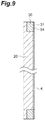
- the surface 31 of the second urethane portion 30 may be provided with an adhesive layer 54 as in a second modification example illustrated in FIG. 9 .
- the adhesive layer 54 is, for an example, a double-sided tape or the like and is provided over the entire surface 31.
- thickness reduction can be achieved and attachability can be ensured as in the above embodiment.
- the air filter 4 can be attached to the housing 2 by the adhesive layer 54, and thus the attachability of the air filter 4 can be ensured in an even more reliable manner.
- the through hole 41 may not be provided in the second modification example. In this case, the air filter 4 may be attached to the housing 2 only by the adhesive layer 54 without the screw 42 being used.
- the second urethane portion 30 may have a linear connecting portion 36 interconnecting the pair of long side portions as in a third modification example illustrated in FIG. 10A .
- the second urethane portion 30 may further have the linear connecting portion 36 interconnecting a pair of short side portions in the third modification example.
- thickness reduction can be achieved and attachability can be ensured as in the above embodiment.
- the rigidity of the second urethane portion 30 can be effectively enhanced because the connecting portion 36 is provided.
- the shape of the second urethane portion 30 in the third and fourth modification examples is particularly effective in a case where the planar shape of the air filter 4 is large.
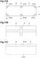
- the second urethane portion 30 may be constituted by four parts 37 overlapping with the four corner portions of the first urethane portion 20 in front view as in a fifth modification example illustrated in FIG. 11A .
- the through hole 41 may be formed at each part 37.
- the second urethane portion 30 may have a cross shape in front view as in a sixth modification example illustrated in FIG 11B .
- the second urethane portion 30 may be constituted by a pair of linear portions 38 overlapping with a pair of facing side portions of the first urethane portion 20 in front view as in a seventh modification example illustrated in FIG. 11C . Also with the air filter 4 of the fifth to seventh modification examples, thickness reduction can be achieved and attachability can be ensured as in the above embodiment.
- the air filter 4 may be applied to devices other than the light source device 1.
- the air filter 4 may be applied to a device in which a housing incorporates a heat generation unit (such as a light source, a light receiving portion, and a drive circuit) that generates heat in operation, air needs to flow into the housing, and dust intrusion into the housing needs to be prevented.
- the air filter 4 may be applied to radiation source devices such as X-ray devices, electron beam source devices, various light receiving devices, radiation detection devices, radiation imaging devices, projection devices (projectors), personal computers, and the like.
Landscapes
- Chemical & Material Sciences (AREA)
- Chemical Kinetics & Catalysis (AREA)
- Filtering Of Dispersed Particles In Gases (AREA)
- Filtering Materials (AREA)
- Laminated Bodies (AREA)
Abstract
Description
- An aspect of the present disclosure relates to an air filter, a light source device, and an air filter manufacturing method.
- Japanese Unexamined Patent Publication No.
2002-174855 - A device to which the air filter is applied may need to be reduced in size and the air filter may need to be reduced in thickness. However, simple air filter thickness reduction may lead to an increase in the complexity of air filter attachment to the housing. In addition, a separate frame member is necessary for the air filter to be sandwiched and fixed between the housing and the frame member, and then no sufficient device size reduction may be possible.
- An object of an aspect of the present disclosure is to provide an air filter that can be reduced in thickness with attachability ensured, a light source device that can be reduced in size, and an air filter manufacturing method for such an air filter.
- An air filter according to an aspect of the present disclosure includes a first urethane portion made of polyurethane foam and having air permeability and a second urethane portion made of polyurethane foam and disposed so as to overlap with a part of the first urethane portion. The second urethane portion is higher in density than the first urethane portion. The first urethane portion and the second urethane portion are integrated with each other in a state where the second urethane portion is incorporated in the part of the first urethane portion.
- In this air filter, the air-permeable first urethane portion made of polyurethane foam and the second urethane portion made of polyurethane foam are integrated with each other in a state where the second urethane portion is incorporated in the part of the first urethane portion. As a result, it is possible to omit a frame member as described above and it is possible to reduce the thickness of the air filter. In addition, because the density of the second urethane portion is higher than the density of the first urethane portion, rigidity can be ensured for the air filter even after the air filter is reduced in thickness and handling of the air filter can be facilitated. Further, the air filter can be easily fixed to an attachment target (such as a housing) in the high-density second urethane portion even after the air filter is reduced in thickness. Accordingly, the air filter can be reduced in thickness with attachability ensured.
- A recess may be provided in a surface of the first urethane portion and the second urethane portion may be disposed in the recess such that a surface of the second urethane portion is flush with the surface of the first urethane portion. In this case, the thickness of the air filter can be further reduced.
- The air filter according to an aspect of the present disclosure may further include a metallic mesh member disposed between the first urethane portion and the second urethane portion. In this case, the rigidity of the air filter can be enhanced and the attachability of the air filter can be ensured in a more reliable manner.
- The second urethane portion may be formed in a frame shape and disposed along an outer edge of the first urethane portion. In this case, the attachability of the air filter can be ensured in an even more reliable manner.
- A through hole may be provided so as to penetrate the first urethane portion and the second urethane portion. In this case, it is possible to attach the air filter to an attachment target by, for example, inserting a screw into the through hole and it is possible to ensure the attachability of the air filter in an even more reliable manner.
- An adhesive layer may be provided on a surface of the second urethane portion. In this case, the air filter can be attached to an attachment target by, for example, the adhesive layer and the attachability of the air filter can be ensured in an even more reliable manner.
- An opening penetrating the first urethane portion may be provided at a remaining part of the first urethane portion other than the part. In this case, the air filter can be attached to an attachment target such that a protruding portion is disposed in the opening in a case where, for example, the protruding portion (such as a terminal portion) is provided at the air filter attachment position in the attachment target and the attachability of the air filter can be ensured in an even more reliable manner.
- A light source device according to an aspect of the present disclosure includes the air filter and a housing provided with an intake port and accommodating a light source. The air filter is disposed so as to cover the intake port and fixed to the housing in the second urethane portion. This light source device includes the air filter, which can be reduced in thickness with attachability ensured as described above, and thus the light source device can be reduced in size.
- An air filter manufacturing method according to an aspect of the present disclosure includes an overlapping step of overlapping a first urethane member made of polyurethane foam and having air permeability and a second urethane member made of polyurethane foam and higher in density than the first urethane member with each other such that the second urethane member overlaps a part of the first urethane member and an integration step of integrating the first urethane member and the second urethane member with each other by thermocompression bonding after the overlapping step.
- In this air filter manufacturing method, the air-permeable first urethane member made of polyurethane foam and the second urethane member made of polyurethane foam are overlapped with each other and integrated with each other by thermocompression bonding. As a result, it is possible to omit the above-mentioned frame member and it is possible to obtain the thickness-reduced air filter. In the obtained air filter, the part that the second urethane member constitutes is higher in density than the part that the first urethane member constitutes. Accordingly, rigidity can be ensured for the air filter even after the air filter is reduced in thickness and handling of the air filter can be facilitated. Further, even in a case where the air filter is reduced in thickness, it is possible to easily fix the air filter to an attachment target (such as a housing) at the part that the second urethane member constitutes. As described above, the air filter that can be reduced in thickness with attachability ensured can be obtained by the air filter manufacturing method.
- In the integration step, the first urethane member and the second urethane member may be integrated with each other by thermocompression bonding in a state where the first urethane member and the second urethane member are directly overlapped with each other. In this case, the thickness of the air filter can be further reduced.
- In the overlapping step, the first urethane member, the second urethane member, and a metallic mesh member may be mutually overlapped such that the mesh member is disposed between the first urethane member and the second urethane member. In the integration step, the first urethane member and the second urethane member may be integrated with each other by thermocompression bonding in a state where the mesh member is disposed between the first urethane member and the second urethane member. In this case, the rigidity of the air filter can be enhanced and the attachability of the air filter can be ensured in a more reliable manner.
- The air filter manufacturing method according to an aspect of the present disclosure may further include a step of forming a through hole after the integration step, the through hole penetrating the first urethane member and the second urethane member. In this case, it is possible to attach the air filter to an attachment target by, for example, inserting a screw into the through hole and it is possible to ensure the attachability of the air filter in an even more reliable manner.
- The air filter manufacturing method according to an aspect of the present disclosure may further include a step of forming an adhesive layer on a surface of the second urethane member after the integration step. In this case, the air filter can be attached to an attachment target by, for example, the adhesive layer and the attachability of the air filter can be ensured in an even more reliable manner.
- The air filter manufacturing method according to an aspect of the present disclosure may further include a step of forming an opening at a remaining part of the first urethane member other than the part after the integration step, the opening penetrating the first urethane member. In this case, the air filter can be attached to an attachment target such that a protruding portion is disposed in the opening in a case where, for example, the protruding portion (such as a terminal portion) is provided at the air filter attachment position in the attachment target and the attachability of the air filter can be ensured in an even more reliable manner.
- According to an aspect of the present disclosure, it is possible to provide an air filter that can be reduced in thickness with attachability ensured, a light source device that can be reduced in size, and an air filter manufacturing method.
-
-
FIG. 1 is a perspective view in which a light source device provided with an air filter according to an embodiment is viewed from the front side. -
FIG. 2 is a perspective view in which the light source device illustrated inFIG. 1 is viewed from the back side. -
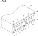
FIG. 3 is a diagram illustrating a state where the air filter is removed inFIG. 2 . -
FIG. 4 is a front view of the air filter. -
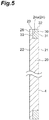
FIG. 5 is a cross-sectional view taken along line V-V illustrated inFIG. 4 . -
FIGS. 6A and 6B are diagrams illustrating an air filter manufacturing method. -
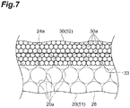
FIG. 7 is a schematic diagram illustrating a joint between a first urethane portion and a second urethane portion. -
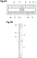
FIG. 8A is a front view of an air filter according to a first modification example, andFIG. 8B is a cross-sectional view taken along line B-B illustrated inFIG. 8A . -
FIG. 9 is a cross-sectional view of an air filter according to a second modification example. -
FIG 10A is a front view of an air filter according to a third modification example, andFIG. 10B is a front view of an air filter according to a fourth modification example. -
FIG. 11A is a front view of an air filter according to a fifth modification example,FIG. 11B is a front view of an air filter according to a sixth modification example, andFIG. 11C is a front view of an air filter according to a seventh modification example. - Hereinafter, an embodiment of the present disclosure will be described in detail with reference to accompanying drawings. In the following description, the same or corresponding elements will be denoted by the same reference numerals without redundant description.
- A
light source device 1 illustrated inFIGS. 1 ,2 , and3 is, for example, a high-power air-cooled LED light source. Thelight source device 1 is used as, for example, a light source unit mounted on a UV printing device (UV printer). Thelight source device 1 performs ink drying and the like by emitting light such as ultraviolet light, for example. Thelight source device 1 includes ahousing 2, anLED substrate 3, and anair filter 4. - The
housing 2 is, for example, metallic and formed in a rectangular box shape and accommodates theLED substrate 3. Thehousing 2 may further accommodate a heat sink thermally connected to theLED substrate 3, an electric circuit board provided with a drive circuit of thelight source device 1, a fan pumping air, and the like. - The
housing 2 has afront surface 11, aback surface 12, and aside surface 13. Thefront surface 11 and theback surface 12 face each other in the direction orthogonal to thefront surface 11. Theside surface 13 extends along the direction orthogonal to thefront surface 11 and is continuous with thefront surface 11 and theback surface 12. Thefront surface 11 is provided with atransparent emission window 14. Theback surface 12 is provided with a plurality of (five in this example)intake ports 15 for suctioning air into thehousing 2 from the outside. Although eachintake port 15 has, for example, a substantially rectangular cross-sectional shape, the number, shape, size, and disposition of theintake ports 15 may be set in any manner. Theside surface 13 may be provided with a discharge port for discharging air to the outside from the inside of thehousing 2. In thehousing 2, air flows from theintake port 15 side toward the discharge port side. - The
back surface 12 is further provided with a pair ofterminal portions 18 and a plurality of (six in this example)screw receiving portions 19. Eachterminal portion 18 is electrically connected to an internal circuit such as the electric circuit board. A cable for communication with the outside or the like is connected to eachterminal portion 18. Eachterminal portion 18 protrudes from theback surface 12 to the side opposite to thefront surface 11. The plurality ofscrew receiving portions 19 are respectively disposed at positions corresponding to the positions of a plurality of throughholes 41, which will be described later. - The
LED substrate 3 has, for example, a substrate constituting a predetermined circuit and a plurality of LED elements (light sources) provided side by side on the substrate. TheLED substrate 3 is disposed on thefront surface 11 side in thehousing 2. The light emitted from each LED element is emitted to an irradiation object through theemission window 14. - The
air filter 4 is a filter for protecting the inside of thehousing 2 from, for example, the dust and the mist that are contained in air suctioned into thehousing 2. Theair filter 4 is formed in a flat plate shape and is attached to thehousing 2 so as to cover eachintake port 15. In the present embodiment, theair filter 4 is formed in a rectangular plate shape corresponding to the shape of theback surface 12 and covers theentire back surface 12. For example, the length of the long side of theair filter 4 is approximately 100 mm and the length of the short side of theair filter 4 is approximately 40 mm. - As illustrated in
FIGS. 4 and5 , theair filter 4 includes afirst urethane portion 20 and asecond urethane portion 30. Theair filter 4 is formed symmetrically with respect to a plane passing through the center of theair filter 4 and orthogonal to the long side of theair filter 4. Theair filter 4 is formed symmetrically with respect to a plane passing through the center of theair filter 4 and orthogonal to the short side of theair filter 4. Theair filter 4 may not necessarily be formed symmetrically with respect to the planes. - The
first urethane portion 20 is formed in a substantially rectangular plate shape. Thefirst urethane portion 20 has afirst surface 21 and asecond surface 22 facing each other and aside surface 23 continuous with thefirst surface 21 and thesecond surface 22. Thefirst surface 21 is provided with arecess 24 having a shape corresponding to thesecond urethane portion 30. In the present embodiment, therecess 24 is a groove portion extending along the outer edge of thefirst urethane portion 20. Therecess 24 has a substantially rectangular ring shape in a cross section along thefirst surface 21 and has a rectangular shape in a cross section orthogonal to the extending direction of therecess 24. The thickness of thefirst urethane portion 20 in the direction orthogonal to the first surface 21 (that is, the distance between thefirst surface 21 and the second surface 22) is, for example, approximately 1.5 mm. - The
second urethane portion 30 is formed in a substantially rectangular frame shape. Thesecond urethane portion 30 is disposed so as to overlap with apart 26 of thefirst urethane portion 20 in front view (that is, when viewed from the direction orthogonal to the first surface 21). Thesecond urethane portion 30 is disposed in therecess 24 such that asurface 31 of thesecond urethane portion 30 is flush with thefirst surface 21 of thefirst urethane portion 20. In other words, thesurface 31 is positioned on the same plane as thefirst surface 21. Thesecond urethane portion 30 is disposed in therecess 24 without a gap. Thesecond urethane portion 30 is disposed along the outer edge of thefirst urethane portion 20. Aside surface 32, which is continuous with thesurface 31 of thesecond urethane portion 30, is flush with theside surface 23 of thefirst urethane portion 20. Thesecond urethane portion 30 has a substantially rectangular ring shape in a cross section along the first surface 21 (that is, a cross section parallel to the first surface 21) and has a rectangular shape in a cross section orthogonal to the extending direction of thesecond urethane portion 30. The thickness of thesecond urethane portion 30 in the direction orthogonal to thefirst surface 21 is, for example, approximately 10 mm. Thesecond urethane portion 30 is coupled to thepart 26 of thefirst urethane portion 20 at a bottom surface (that is, a surface opposite to the surface 31)33. Details of this coupling will be described later. In the present embodiment, thepart 26 of thefirst urethane portion 20 is a rectangular ring-shaped region extending along the outer edge of thefirst urethane portion 20 and is a region overlapping with abottom surface 24a of therecess 24 in plan view. - The part of the
first urethane portion 20 other than the part 26 (that is, the part not overlapping with thesecond urethane portion 30 in front view) is provided with a pair ofopenings 25 penetrating thefirst urethane portion 20 along the direction orthogonal to thefirst surface 21. Eachopening 25 has a cross-sectional shape corresponding to the outer shape of theterminal portion 18 such that theterminal portion 18 can be inserted through theopening 25, which is disposed at a position corresponding to the position of theterminal portion 18. For example, each opening 25 has a rectangular shape that is larger than theterminal portion 18 in a cross section along thefirst surface 21. The pair ofopenings 25 are respectively disposed on one side and the other side in the direction along the long side of thefirst urethane portion 20 with respect to the center of thefirst urethane portion 20. - The
first urethane portion 20 and thesecond urethane portion 30 are provided with the plurality of (six in this example) throughholes 41 penetrating thefirst urethane portion 20 and thesecond urethane portion 30 along the direction orthogonal to thefirst surface 21. The plurality of throughholes 41 are respectively disposed at positions corresponding to the positions of the plurality ofscrew receiving portions 19. - The
second urethane portion 30 has a throughhole forming portion 34, which protrudes toward the center of thefirst urethane portion 20, in each of four corner portions and the middle portions in two long side portions. The throughhole forming portions 34 that are provided in the long side portions have a semicircular shape. The throughhole forming portions 34 that are provided in the corner portions have a fan shape with a central angle of 90 degrees. The throughhole 41 described above is formed in the throughhole forming portion 34. - The
air filter 4 is fixed to theback surface 12 of thehousing 2 by a plurality ofscrews 42 being respectively inserted through the plurality of throughholes 41 and screwed into thescrew receiving portions 19. In other words, theair filter 4 is fixed to thehousing 2 in thesecond urethane portion 30 by the fastening force of thescrew 42. - Polyurethane foam having an open-cell structure constitutes the
first urethane portion 20. Polyurethane foam may be foam made of polyurethane or urethane sponge, for example. Thefirst urethane portion 20 is configured to include multiple interconnected cells (that is, open cells), has air permeability, and transmits air. In other words, thefirst urethane portion 20 includes open cells open to both thefirst surface 21 and thesecond surface 22. Polyurethane foam having an open-cell structure constitutes thesecond urethane portion 30. - The density of the
second urethane portion 30 is higher than the density of thefirst urethane portion 20. For example, the density of thefirst urethane portion 20 is approximately 30 kg/m3 and the density of thesecond urethane portion 30 is approximately 50 kg/m3. Further, the number of cells per unit length of thesecond urethane portion 30 is larger than the number of cells per unit length of thefirst urethane portion 20. In other words, the size of the cell of thesecond urethane portion 30 is smaller than the size of the cell of thefirst urethane portion 20. For example, the number of cells per unit length of thefirst urethane portion 20 is 8/25 mm to 20/25 mm. - Although the
second urethane portion 30 has an open-cell structure, thesecond urethane portion 30 is higher in density than thefirst urethane portion 20, and thus thesecond urethane portion 30 has no air permeability and hardly transmits air. Thesecond urethane portion 30 may have a closed-cell structure. In this case, thesecond urethane portion 30 is configured to include multiple disconnected cells (that is, closed cells), has no air permeability, and blocks air. Although thesecond urethane portion 30 is, for example, semi-rigid foam, thesecond urethane portion 30 may also be rigid foam or flexible foam. -
FIGS. 6A and 6B are diagrams illustrating a method for manufacturing theair filter 4. During the manufacturing of theair filter 4, afirst urethane member 51 that becomes thefirst urethane portion 20 after processing and asecond urethane member 52 that becomes thesecond urethane portion 30 after processing are overlapped with each other first (overlapping step), as illustrated inFIG 6A , such that thesecond urethane member 52 overlaps with a part of thefirst urethane member 51 when viewed from the direction orthogonal to asurface 51a of the first urethane member 51 (that is, the direction of overlapping of thefirst urethane member 51 and the second urethane member 52). The part of thefirst urethane member 51 becomes thepart 26 of thefirst urethane portion 20 after processing. - Subsequently, as illustrated in
FIG. 6B , thefirst urethane member 51 and thesecond urethane member 52 are integrated with each other by thermocompression bonding (integration step). More specifically, thefirst urethane member 51 and thesecond urethane member 52 are sandwiched by a pair ofheated press portions 5a by means of apress machine 5 having the pair ofpress portions 5a and are heat-pressed for a predetermined time. In the present embodiment, the heat pressing is performed in a state where thefirst urethane member 51 and thesecond urethane member 52 are directly overlapped with each other (that is, in a state where no other member is interposed between thefirst urethane member 51 and the second urethane member 52). The heat pressing is performed for 3 minutes at, for example, 180°C. - In the integration step, the
first urethane member 51 and thesecond urethane member 52 are integrated with (coupled to) each other while being compressed by the heat pressing and are formed into a single flat plate-shaped member, that is, theair filter 4. At this time, the part of thefirst urethane member 51 that overlaps with thesecond urethane member 52 when viewed from the direction orthogonal to thesurface 51a is compressed more than the other part. As a result, in the obtainedair filter 4, therecess 24 is formed in thefirst urethane portion 20 and thesecond urethane portion 30 is disposed in therecess 24 without a gap as described above. - Before the thermocompression bonding, for example, the thickness of the
first urethane member 51 is 3.5 mm and the thickness of thesecond urethane member 52 is 10 mm. After the thermocompression bonding, the total thickness of thefirst urethane member 51 and the second urethane member 52 (that is, the thickness of the air filter 4) is 1.5 mm. The planar shapes of thefirst urethane member 51 and thesecond urethane member 52 hardly change through the thermocompression bonding. Even before the thermocompression bonding, the density of thesecond urethane member 52 is higher than the density of thefirst urethane member 51 and the number of cells per unit length of thesecond urethane member 52 is larger than the number of cells per unit length of thefirst urethane member 51. - A joint part between the first urethane portion 20 (first urethane member 51) and the second urethane portion 30 (second urethane member 52) will be described with reference to
FIG. 7 . Thefirst urethane portion 20 and thesecond urethane portion 30 are integrated with each other in a state where thesecond urethane portion 30 is incorporated in thepart 26 of thefirst urethane portion 20. - The
first urethane portion 20 has an open-cell structure as described above. Thefirst urethane portion 20 includes multipleinterconnected cells 20a. Thefirst urethane portion 20 is lower in density than thesecond urethane portion 30. Accordingly, thefirst urethane portion 20 is sparser in structure than thesecond urethane portion 30. Thesecond urethane portion 30 has an open-cell structure as described above. Thesecond urethane portion 30 includes multipleinterconnected cells 30a. Thesecond urethane portion 30 is higher in density than thefirst urethane portion 20. Accordingly, thesecond urethane portion 30 is denser in structure than thefirst urethane portion 20. - Accordingly, once the heat pressing is performed in the integration step, the second urethane portion 30 (the fiber of the
second urethane portion 30 to be specific) enters thecells 20a at thepart 26 in the boundary portion between thepart 26 of thefirst urethane portion 20 and the second urethane portion 30 (that is, the contact portion between thebottom surface 24a of therecess 24 in thefirst urethane portion 20 and thebottom surface 33 of the second urethane portion 30). As a result, thefirst urethane portion 20 and thesecond urethane portion 30 are integrated with each other. Thepart 26 of thefirst urethane portion 20 and thesecond urethane portion 30 may be intertwined with each other. Although thecells 20a are not interconnected inFIG 7 , thecells 20a are interconnected in practice. The same applies to thecells 30a. Although thecells FIG. 7 , thecells - Returning to the method for manufacturing the
air filter 4, the plurality of throughholes 41 penetrating thefirst urethane member 51 and thesecond urethane member 52 are formed subsequently to the integration step. Subsequently, the pair ofopenings 25 penetrating thefirst urethane member 51 are formed at the part other than the part of thefirst urethane member 51 overlapping with thesecond urethane member 52. Theair filter 4 is obtained as a result of the above steps. Each of the above steps may be carried out by, for example, a worker and/or a work machine. - As described above, in the
air filter 4, the air-permeablefirst urethane portion 20 made of polyurethane foam and thesecond urethane portion 30 made of polyurethane foam are integrated with each other in a state where thesecond urethane portion 30 is incorporated (inserted) in thepart 26 of thefirst urethane portion 20. As a result, it is possible to omit a frame member for holding a filter member as described above or a frame member sandwiching and fixing an air filter between a housing and the frame member and it is possible to reduce the thickness of theair filter 4. In addition, because the density of thesecond urethane portion 30 is higher than the density of thefirst urethane portion 20, rigidity can be ensured for theair filter 4 even after theair filter 4 is reduced in thickness and handling of theair filter 4 can be facilitated. Further, theair filter 4 can be easily fixed to an attachment target (such as the housing 2) in the high-densitysecond urethane portion 30 even after theair filter 4 is reduced in thickness. Accordingly, theair filter 4 can be reduced in thickness with attachability ensured. - In the
air filter 4, thefirst surface 21 of thefirst urethane portion 20 is provided with therecess 24 and thesecond urethane portion 30 is disposed in therecess 24 such that thesurface 31 of thesecond urethane portion 30 is flush with thefirst surface 21 of thefirst urethane portion 20. As a result, the thickness of theair filter 4 can be further reduced. - In the
air filter 4, thesecond urethane portion 30 is formed in a frame shape and is disposed along the outer edge of thefirst urethane portion 20. As a result, the attachability of theair filter 4 can be ensured in a more reliable manner. - The
air filter 4 is provided with the throughhole 41 penetrating thefirst urethane portion 20 and thesecond urethane portion 30. As a result, it is possible to attach theair filter 4 to thehousing 2 by, for example, inserting thescrew 42 into the throughhole 41 and it is possible to ensure the attachability of theair filter 4 in an even more reliable manner. - In the
air filter 4, the remaining part of thefirst urethane portion 20 other than thepart 26 is provided with theopening 25 penetrating thefirst urethane portion 20. As a result, it is possible to attach theair filter 4 to thehousing 2 such that, for example, theterminal portion 18 is disposed in theopening 25 and it is possible to ensure the attachability of theair filter 4 in an even more reliable manner. - In the
light source device 1, theair filter 4 is disposed so as to cover theintake port 15 and is fixed to thehousing 2 in thesecond urethane portion 30. Thelight source device 1 is provided with theair filter 4, which can be reduced in thickness with attachability ensured as described above, and thus thelight source device 1 can be reduced in size. - In the method for manufacturing the
air filter 4, the air-permeablefirst urethane member 51 made of polyurethane foam and thesecond urethane member 52 made of polyurethane foam are overlapped with each other and integrated with each other by thermocompression bonding. As a result, it is possible to omit the frame member and it is possible to obtain the thickness-reducedair filter 4. In the obtainedair filter 4, the part that thesecond urethane member 52 constitutes (that is, the second urethane portion 30) is higher in density than the part that thefirst urethane member 51 constitutes (that is, the first urethane portion 20). Accordingly, rigidity can be ensured for theair filter 4 even after theair filter 4 is reduced in thickness and handling of theair filter 4 can be facilitated. Further, even in a case where theair filter 4 is reduced in thickness, it is possible to easily fix theair filter 4 to thehousing 2 at the part that thesecond urethane member 52 constitutes. As described above, theair filter 4 that can be reduced in thickness with attachability ensured can be obtained by the method for manufacturing theair filter 4. - The present disclosure is not limited to the embodiment of the present disclosure described above. For example, the
air filter 4 may be further include ametallic mesh member 53 disposed between thefirst urethane portion 20 and thesecond urethane portion 30 as in a first modification example illustrated inFIGS. 8A and 8B . Themesh member 53 has, for example, a rectangular outer shape corresponding to the outer shape of thefirst urethane portion 20. In the first modification example, therecess 24 is not formed in thefirst surface 21 of thefirst urethane portion 20 and thefirst surface 21 is a flat surface. During manufacturing of theair filter 4 of the first modification example, thefirst urethane member 51 and thesecond urethane member 52 are integrated with each other by thermocompression bonding in the integration step with themesh member 53 disposed between thefirst urethane member 51 and thesecond urethane member 52. In theair filter 4 of the first modification example, thefirst urethane portion 20 and thesecond urethane portion 30 are integrated with each other in a state where thesecond urethane portion 30 has entered thepart 26 of thefirst urethane portion 20 through themesh member 53. - In the first modification example, the
mesh member 53 has a mesh spacing of 2 mm or more such that thesecond urethane portion 30 is capable of easily entering the gap formed between the meshes of themesh member 53. This is based on the knowledge that thefirst urethane portion 20 and thesecond urethane portion 30 are satisfactorily coupled to each other in a case where themesh member 53 has a mesh diameter of 0.5 mm and a mesh spacing of 2.5 mm whereas thefirst urethane portion 20 and thesecond urethane portion 30 easily peel without being satisfactorily coupled to each other in a case where themesh member 53 has a mesh diameter of 0.2 mm and a mesh spacing of 1 mm. Also with theair filter 4 of the first modification example, thickness reduction can be achieved and attachability can be ensured as in the above embodiment. Further, theair filter 4 of the first modification example is further include themetallic mesh member 53 disposed between thefirst urethane portion 20 and thesecond urethane portion 30. Accordingly, the rigidity of theair filter 4 can be enhanced and the attachability of theair filter 4 can be ensured in an even more reliable manner. - The
surface 31 of thesecond urethane portion 30 may be provided with an adhesive layer 54 as in a second modification example illustrated inFIG. 9 . The adhesive layer 54 is, for an example, a double-sided tape or the like and is provided over theentire surface 31. Also with theair filter 4 of the second modification example, thickness reduction can be achieved and attachability can be ensured as in the above embodiment. Further, theair filter 4 can be attached to thehousing 2 by the adhesive layer 54, and thus the attachability of theair filter 4 can be ensured in an even more reliable manner. The throughhole 41 may not be provided in the second modification example. In this case, theair filter 4 may be attached to thehousing 2 only by the adhesive layer 54 without thescrew 42 being used. In a case where thescrew 42 and the adhesive layer 54 are used in combination, the adhesion between theair filter 4 and thehousing 2 can be improved and theair filter 4 can be more firmly fixed to thehousing 2. The adhesive layer 54 may be provided on thesurface 31 of thesecond urethane portion 30 in the first modification example described above. - The
second urethane portion 30 may have a linear connectingportion 36 interconnecting the pair of long side portions as in a third modification example illustrated inFIG. 10A . As in a fourth modification example illustrated inFIG. 10B , thesecond urethane portion 30 may further have the linear connectingportion 36 interconnecting a pair of short side portions in the third modification example. Also with theair filter 4 of the third and fourth modification examples, thickness reduction can be achieved and attachability can be ensured as in the above embodiment. Further, in the third and fourth modification examples, the rigidity of thesecond urethane portion 30 can be effectively enhanced because the connectingportion 36 is provided. The shape of thesecond urethane portion 30 in the third and fourth modification examples is particularly effective in a case where the planar shape of theair filter 4 is large. - The
second urethane portion 30 may be constituted by fourparts 37 overlapping with the four corner portions of thefirst urethane portion 20 in front view as in a fifth modification example illustrated inFIG. 11A . The throughhole 41 may be formed at eachpart 37. Thesecond urethane portion 30 may have a cross shape in front view as in a sixth modification example illustrated inFIG 11B . Thesecond urethane portion 30 may be constituted by a pair oflinear portions 38 overlapping with a pair of facing side portions of thefirst urethane portion 20 in front view as in a seventh modification example illustrated inFIG. 11C . Also with theair filter 4 of the fifth to seventh modification examples, thickness reduction can be achieved and attachability can be ensured as in the above embodiment. In the embodiment and each modification example, various materials and shapes can be adopted, without being limited to the above-described material and shape, for the material and shape of each configuration. Theair filter 4 may be applied to devices other than thelight source device 1. For example, theair filter 4 may be applied to a device in which a housing incorporates a heat generation unit (such as a light source, a light receiving portion, and a drive circuit) that generates heat in operation, air needs to flow into the housing, and dust intrusion into the housing needs to be prevented. For example, theair filter 4 may be applied to radiation source devices such as X-ray devices, electron beam source devices, various light receiving devices, radiation detection devices, radiation imaging devices, projection devices (projectors), personal computers, and the like.
Claims (14)
- An air filter comprising:a first urethane portion made of polyurethane foam and having air permeability; anda second urethane portion made of polyurethane foam and disposed so as to overlap with a part of the first urethane portion, whereinthe second urethane portion is higher in density than the first urethane portion, andthe first urethane portion and the second urethane portion are integrated with each other in a state where the second urethane portion is incorporated in the part of the first urethane portion.
- The air filter according to claim 1, wherein
a recess is provided in a surface of the first urethane portion, and
the second urethane portion is disposed in the recess such that a surface of the second urethane portion is flush with the surface of the first urethane portion. - The air filter according to claim 1, further comprising a metallic mesh member disposed between the first urethane portion and the second urethane portion.
- The air filter according to any one of claims 1 to 3, wherein the second urethane portion is formed in a frame shape and disposed along an outer edge of the first urethane portion.
- The air filter according to any one of claims 1 to 4, wherein a through hole is provided so as to penetrate the first urethane portion and the second urethane portion.
- The air filter according to any one of claims 1 to 5, wherein an adhesive layer is provided on a surface of the second urethane portion.
- The air filter according to any one of claims 1 to 6, wherein an opening penetrating the first urethane portion is provided at a remaining part of the first urethane portion other than the part.
- A light source device comprising:the air filter according to any one of claims 1 to 7; anda housing provided with an intake port and accommodating a light source,wherein the air filter is disposed so as to cover the intake port and fixed to the housing in the second urethane portion.
- An air filter manufacturing method comprising:an overlapping step of overlapping a first urethane member made of polyurethane foam and having air permeability and a second urethane member made of polyurethane foam and higher in density than the first urethane member with each other such that the second urethane member overlaps a part of the first urethane member; andan integration step of integrating the first urethane member and the second urethane member with each other by thermocompression bonding after the overlapping step.
- The air filter manufacturing method according to claim 9, wherein in the integration step, the first urethane member and the second urethane member are integrated with each other by thermocompression bonding in a state where the first urethane member and the second urethane member are directly overlapped with each other.
- The air filter manufacturing method according to claim 9, wherein
in the overlapping step, the first urethane member, the second urethane member, and a metallic mesh member are mutually overlapped such that the mesh member is disposed between the first urethane member and the second urethane member, and
in the integration step, the first urethane member and the second urethane member are integrated with each other by thermocompression bonding in a state where the mesh member is disposed between the first urethane member and the second urethane member. - The air filter manufacturing method according to any one of claims 9 to 11, further comprising a step of forming a through hole after the integration step, the through hole penetrating the first urethane member and the second urethane member.
- The air filter manufacturing method according to any one of claims 9 to 12, further comprising a step of forming an adhesive layer on a surface of the second urethane member after the integration step.
- The air filter manufacturing method according to any one of claims 9 to 13, further comprising a step of forming an opening at a remaining part of the first urethane member other than the part after the integration step, the opening penetrating the first urethane member.
Applications Claiming Priority (1)
| Application Number | Priority Date | Filing Date | Title |
|---|---|---|---|
| JP2018107901A JP7105622B2 (en) | 2018-06-05 | 2018-06-05 | AIR FILTER, LIGHT SOURCE DEVICE, AND AIR FILTER MANUFACTURING METHOD |
Publications (2)
| Publication Number | Publication Date |
|---|---|
| EP3578246A1 true EP3578246A1 (en) | 2019-12-11 |
| EP3578246B1 EP3578246B1 (en) | 2020-09-16 |
Family
ID=66676169
Family Applications (1)
| Application Number | Title | Priority Date | Filing Date |
|---|---|---|---|
| EP19173682.6A Active EP3578246B1 (en) | 2018-06-05 | 2019-05-10 | Air filter, light source device, and air filter manufacturing method |
Country Status (5)
| Country | Link |
|---|---|
| US (1) | US11229866B2 (en) |
| EP (1) | EP3578246B1 (en) |
| JP (1) | JP7105622B2 (en) |
| DK (1) | DK3578246T3 (en) |
| ES (1) | ES2831501T3 (en) |
Families Citing this family (1)
| Publication number | Priority date | Publication date | Assignee | Title |
|---|---|---|---|---|
| USD947346S1 (en) * | 2020-12-08 | 2022-03-29 | Pablo Garcia Mujica | Air purifier |
Citations (4)
| Publication number | Priority date | Publication date | Assignee | Title |
|---|---|---|---|---|
| GB894732A (en) * | 1960-01-12 | 1962-04-26 | Gen Motors Ltd | Improvements in and relating to filters for gases |
| JP2002174855A (en) | 2000-09-29 | 2002-06-21 | Sony Corp | Projection display device |
| JP2005336697A (en) * | 2004-04-30 | 2005-12-08 | Toyo Quality One Corp | Clothing / clothing pad, manufacturing method thereof and clothing / clothing |
| US20080072868A1 (en) * | 2005-03-31 | 2008-03-27 | Akira Sasaki | Air cleaner for motorcycles |
Family Cites Families (18)
| Publication number | Priority date | Publication date | Assignee | Title |
|---|---|---|---|---|
| US4152183A (en) * | 1977-01-14 | 1979-05-01 | Dart Industries, Inc. | Method for producing hollow cylindrical structures |
| JPS5398563A (en) * | 1977-02-10 | 1978-08-29 | Oshima Kazue | Method of fabricating filter element from urethane foam |
| JPS6137213U (en) | 1984-08-09 | 1986-03-07 | 井上エムテ−ピ−株式会社 | air filter |
| JPS62176512A (en) * | 1986-01-30 | 1987-08-03 | Inoue Mtp Co Ltd | Manufacture of air filter |
| JPS62126212U (en) | 1986-01-30 | 1987-08-11 | ||
| JP3424998B2 (en) * | 1995-01-05 | 2003-07-07 | 株式会社エッチ・ケー・エス | Air filter device for engine intake |
| JP2001000816A (en) * | 1999-06-21 | 2001-01-09 | Satoyoshi Seisakusho:Kk | Air filter structure |
| TWI296538B (en) * | 2001-12-28 | 2008-05-11 | Chao-Ming Wang | A foam filter and the manufacturing method thereof |
| US6926828B2 (en) * | 2002-01-25 | 2005-08-09 | Inoac Corporation | Fluid filter |
| TWI353303B (en) * | 2004-09-07 | 2011-12-01 | Toray Industries | Sandwich structure and integrated molding using th |
| US20070175192A1 (en) * | 2006-02-01 | 2007-08-02 | Advanced Flow Engineering, Inc. | Pleated hybrid air filter |
| GB2440515B (en) * | 2006-08-01 | 2011-06-15 | Dyson Technology Ltd | A filter assembly |
| KR20090091294A (en) * | 2006-12-21 | 2009-08-27 | 니폰 가세이 가부시키가이샤 | Humidity sheet |
| JP2011255298A (en) * | 2010-06-08 | 2011-12-22 | Sanyo Electric Co Ltd | Air filter device and projection-type picture displaying device using the same |
| JP2012011326A (en) | 2010-07-01 | 2012-01-19 | Hiramatsu Sangyo Kk | Filter material, filter, and device |
| JP5609334B2 (en) * | 2010-07-06 | 2014-10-22 | 東洋紡株式会社 | Spunbond nonwoven fabric and filter using the same |
| US20180133632A1 (en) * | 2016-11-11 | 2018-05-17 | Hollingsworth & Vose Company | Filter media having a density variation |
| BE1025309B1 (en) * | 2017-06-12 | 2019-01-24 | Atlas Copco Airpower Naamloze Vennootschap | Drainage medium for coalescing filter |
-
2018
- 2018-06-05 JP JP2018107901A patent/JP7105622B2/en not_active Expired - Fee Related
-
2019
- 2019-05-10 EP EP19173682.6A patent/EP3578246B1/en active Active
- 2019-05-10 ES ES19173682T patent/ES2831501T3/en active Active
- 2019-05-10 DK DK19173682.6T patent/DK3578246T3/en active
- 2019-06-04 US US16/430,786 patent/US11229866B2/en not_active Expired - Fee Related
Patent Citations (4)
| Publication number | Priority date | Publication date | Assignee | Title |
|---|---|---|---|---|
| GB894732A (en) * | 1960-01-12 | 1962-04-26 | Gen Motors Ltd | Improvements in and relating to filters for gases |
| JP2002174855A (en) | 2000-09-29 | 2002-06-21 | Sony Corp | Projection display device |
| JP2005336697A (en) * | 2004-04-30 | 2005-12-08 | Toyo Quality One Corp | Clothing / clothing pad, manufacturing method thereof and clothing / clothing |
| US20080072868A1 (en) * | 2005-03-31 | 2008-03-27 | Akira Sasaki | Air cleaner for motorcycles |
Also Published As
| Publication number | Publication date |
|---|---|
| US20190366253A1 (en) | 2019-12-05 |
| EP3578246B1 (en) | 2020-09-16 |
| US11229866B2 (en) | 2022-01-25 |
| JP7105622B2 (en) | 2022-07-25 |
| ES2831501T3 (en) | 2021-06-08 |
| JP2019209264A (en) | 2019-12-12 |
| DK3578246T3 (en) | 2020-11-09 |
Similar Documents
| Publication | Publication Date | Title |
|---|---|---|
| EP3811747B1 (en) | Electronic device including shielding member connected to conductive plate covering opening of shield can | |
| US10516814B2 (en) | Camera assembly and electronic device | |
| WO2021190199A1 (en) | Electronic apparatus | |
| KR20230079431A (en) | Electronics | |
| CN217386607U (en) | Display module assembly and display screen | |
| KR102589854B1 (en) | Electronic Device | |
| KR102090629B1 (en) | Speaker device and electronic device with the same | |
| CN111405414A (en) | Electronic device | |
| CN110087167A (en) | Terminal device | |
| JP2005062777A (en) | Display device | |
| US11229866B2 (en) | Air filter, light source device, and air filter manufacturing method | |
| KR102077140B1 (en) | A flexible display module | |
| US11212605B1 (en) | Microphone bracket for cosmetic port with no mesh | |
| US20190274225A1 (en) | Portable operation device | |
| CN209749010U (en) | Motherboard and its cooling device | |
| CN207283961U (en) | Display and patient monitor | |
| JP2015131406A (en) | Portable electronic device | |
| CN212115388U (en) | Mobile phone motherboard frame | |
| CN210406065U (en) | Shielding case and circuit board with same | |
| US9122086B2 (en) | Display apparatus | |
| CN116456591A (en) | Electronic equipment | |
| CN217238463U (en) | Optical transceiver module and optical network device | |
| CN116153208B (en) | Display device | |
| JP6521934B2 (en) | Electronic device | |
| CN217444175U (en) | Electronic device protective belt and interactive flat plate |
Legal Events
| Date | Code | Title | Description |
|---|---|---|---|
| PUAI | Public reference made under article 153(3) epc to a published international application that has entered the european phase |
Free format text: ORIGINAL CODE: 0009012 |
|
| STAA | Information on the status of an ep patent application or granted ep patent |
Free format text: STATUS: THE APPLICATION HAS BEEN PUBLISHED |
|
| AK | Designated contracting states |
Kind code of ref document: A1 Designated state(s): AL AT BE BG CH CY CZ DE DK EE ES FI FR GB GR HR HU IE IS IT LI LT LU LV MC MK MT NL NO PL PT RO RS SE SI SK SM TR |
|
| AX | Request for extension of the european patent |
Extension state: BA ME |
|
| STAA | Information on the status of an ep patent application or granted ep patent |
Free format text: STATUS: REQUEST FOR EXAMINATION WAS MADE |
|
| 17P | Request for examination filed |
Effective date: 20200316 |
|
| RBV | Designated contracting states (corrected) |
Designated state(s): AL AT BE BG CH CY CZ DE DK EE ES FI FR GB GR HR HU IE IS IT LI LT LU LV MC MK MT NL NO PL PT RO RS SE SI SK SM TR |
|
| GRAP | Despatch of communication of intention to grant a patent |
Free format text: ORIGINAL CODE: EPIDOSNIGR1 |
|
| STAA | Information on the status of an ep patent application or granted ep patent |
Free format text: STATUS: GRANT OF PATENT IS INTENDED |
|
| INTG | Intention to grant announced |
Effective date: 20200528 |
|
| GRAS | Grant fee paid |
Free format text: ORIGINAL CODE: EPIDOSNIGR3 |
|
| GRAA | (expected) grant |
Free format text: ORIGINAL CODE: 0009210 |
|
| STAA | Information on the status of an ep patent application or granted ep patent |
Free format text: STATUS: THE PATENT HAS BEEN GRANTED |
|
| AK | Designated contracting states |
Kind code of ref document: B1 Designated state(s): AL AT BE BG CH CY CZ DE DK EE ES FI FR GB GR HR HU IE IS IT LI LT LU LV MC MK MT NL NO PL PT RO RS SE SI SK SM TR |
|
| REG | Reference to a national code |
Ref country code: GB Ref legal event code: FG4D |
|
| REG | Reference to a national code |
Ref country code: CH Ref legal event code: EP |
|
| REG | Reference to a national code |
Ref country code: DE Ref legal event code: R096 Ref document number: 602019000694 Country of ref document: DE |
|
| REG | Reference to a national code |
Ref country code: IE Ref legal event code: FG4D |
|
| REG | Reference to a national code |
Ref country code: AT Ref legal event code: REF Ref document number: 1313642 Country of ref document: AT Kind code of ref document: T Effective date: 20201015 |
|
| REG | Reference to a national code |
Ref country code: DK Ref legal event code: T3 Effective date: 20201103 |
|
| PG25 | Lapsed in a contracting state [announced via postgrant information from national office to epo] |
Ref country code: NO Free format text: LAPSE BECAUSE OF FAILURE TO SUBMIT A TRANSLATION OF THE DESCRIPTION OR TO PAY THE FEE WITHIN THE PRESCRIBED TIME-LIMIT Effective date: 20201216 Ref country code: GR Free format text: LAPSE BECAUSE OF FAILURE TO SUBMIT A TRANSLATION OF THE DESCRIPTION OR TO PAY THE FEE WITHIN THE PRESCRIBED TIME-LIMIT Effective date: 20201217 Ref country code: SE Free format text: LAPSE BECAUSE OF FAILURE TO SUBMIT A TRANSLATION OF THE DESCRIPTION OR TO PAY THE FEE WITHIN THE PRESCRIBED TIME-LIMIT Effective date: 20200916 Ref country code: HR Free format text: LAPSE BECAUSE OF FAILURE TO SUBMIT A TRANSLATION OF THE DESCRIPTION OR TO PAY THE FEE WITHIN THE PRESCRIBED TIME-LIMIT Effective date: 20200916 Ref country code: FI Free format text: LAPSE BECAUSE OF FAILURE TO SUBMIT A TRANSLATION OF THE DESCRIPTION OR TO PAY THE FEE WITHIN THE PRESCRIBED TIME-LIMIT Effective date: 20200916 Ref country code: BG Free format text: LAPSE BECAUSE OF FAILURE TO SUBMIT A TRANSLATION OF THE DESCRIPTION OR TO PAY THE FEE WITHIN THE PRESCRIBED TIME-LIMIT Effective date: 20201216 |
|
| REG | Reference to a national code |
Ref country code: AT Ref legal event code: MK05 Ref document number: 1313642 Country of ref document: AT Kind code of ref document: T Effective date: 20200916 |
|
| REG | Reference to a national code |
Ref country code: NL Ref legal event code: MP Effective date: 20200916 |
|
| PG25 | Lapsed in a contracting state [announced via postgrant information from national office to epo] |
Ref country code: RS Free format text: LAPSE BECAUSE OF FAILURE TO SUBMIT A TRANSLATION OF THE DESCRIPTION OR TO PAY THE FEE WITHIN THE PRESCRIBED TIME-LIMIT Effective date: 20200916 Ref country code: LV Free format text: LAPSE BECAUSE OF FAILURE TO SUBMIT A TRANSLATION OF THE DESCRIPTION OR TO PAY THE FEE WITHIN THE PRESCRIBED TIME-LIMIT Effective date: 20200916 |
|
| REG | Reference to a national code |
Ref country code: LT Ref legal event code: MG4D |
|
| PG25 | Lapsed in a contracting state [announced via postgrant information from national office to epo] |
Ref country code: EE Free format text: LAPSE BECAUSE OF FAILURE TO SUBMIT A TRANSLATION OF THE DESCRIPTION OR TO PAY THE FEE WITHIN THE PRESCRIBED TIME-LIMIT Effective date: 20200916 Ref country code: RO Free format text: LAPSE BECAUSE OF FAILURE TO SUBMIT A TRANSLATION OF THE DESCRIPTION OR TO PAY THE FEE WITHIN THE PRESCRIBED TIME-LIMIT Effective date: 20200916 Ref country code: PT Free format text: LAPSE BECAUSE OF FAILURE TO SUBMIT A TRANSLATION OF THE DESCRIPTION OR TO PAY THE FEE WITHIN THE PRESCRIBED TIME-LIMIT Effective date: 20210118 Ref country code: CZ Free format text: LAPSE BECAUSE OF FAILURE TO SUBMIT A TRANSLATION OF THE DESCRIPTION OR TO PAY THE FEE WITHIN THE PRESCRIBED TIME-LIMIT Effective date: 20200916 Ref country code: LT Free format text: LAPSE BECAUSE OF FAILURE TO SUBMIT A TRANSLATION OF THE DESCRIPTION OR TO PAY THE FEE WITHIN THE PRESCRIBED TIME-LIMIT Effective date: 20200916 Ref country code: SM Free format text: LAPSE BECAUSE OF FAILURE TO SUBMIT A TRANSLATION OF THE DESCRIPTION OR TO PAY THE FEE WITHIN THE PRESCRIBED TIME-LIMIT Effective date: 20200916 |
|
| PG25 | Lapsed in a contracting state [announced via postgrant information from national office to epo] |
Ref country code: IS Free format text: LAPSE BECAUSE OF FAILURE TO SUBMIT A TRANSLATION OF THE DESCRIPTION OR TO PAY THE FEE WITHIN THE PRESCRIBED TIME-LIMIT Effective date: 20210116 Ref country code: PL Free format text: LAPSE BECAUSE OF FAILURE TO SUBMIT A TRANSLATION OF THE DESCRIPTION OR TO PAY THE FEE WITHIN THE PRESCRIBED TIME-LIMIT Effective date: 20200916 Ref country code: AT Free format text: LAPSE BECAUSE OF FAILURE TO SUBMIT A TRANSLATION OF THE DESCRIPTION OR TO PAY THE FEE WITHIN THE PRESCRIBED TIME-LIMIT Effective date: 20200916 Ref country code: AL Free format text: LAPSE BECAUSE OF FAILURE TO SUBMIT A TRANSLATION OF THE DESCRIPTION OR TO PAY THE FEE WITHIN THE PRESCRIBED TIME-LIMIT Effective date: 20200916 |
|
| REG | Reference to a national code |
Ref country code: ES Ref legal event code: FG2A Ref document number: 2831501 Country of ref document: ES Kind code of ref document: T3 Effective date: 20210608 |
|
| REG | Reference to a national code |
Ref country code: DE Ref legal event code: R097 Ref document number: 602019000694 Country of ref document: DE |
|
| PG25 | Lapsed in a contracting state [announced via postgrant information from national office to epo] |
Ref country code: SK Free format text: LAPSE BECAUSE OF FAILURE TO SUBMIT A TRANSLATION OF THE DESCRIPTION OR TO PAY THE FEE WITHIN THE PRESCRIBED TIME-LIMIT Effective date: 20200916 |
|
| PLBE | No opposition filed within time limit |
Free format text: ORIGINAL CODE: 0009261 |
|
| STAA | Information on the status of an ep patent application or granted ep patent |
Free format text: STATUS: NO OPPOSITION FILED WITHIN TIME LIMIT |
|
| 26N | No opposition filed |
Effective date: 20210617 |
|
| REG | Reference to a national code |
Ref country code: DK Ref legal event code: EBP Effective date: 20210531 |
|
| PG25 | Lapsed in a contracting state [announced via postgrant information from national office to epo] |
Ref country code: MC Free format text: LAPSE BECAUSE OF FAILURE TO SUBMIT A TRANSLATION OF THE DESCRIPTION OR TO PAY THE FEE WITHIN THE PRESCRIBED TIME-LIMIT Effective date: 20200916 Ref country code: LU Free format text: LAPSE BECAUSE OF NON-PAYMENT OF DUE FEES Effective date: 20210510 |
|
| REG | Reference to a national code |
Ref country code: BE Ref legal event code: MM Effective date: 20210531 |
|
| PG25 | Lapsed in a contracting state [announced via postgrant information from national office to epo] |
Ref country code: DK Free format text: LAPSE BECAUSE OF NON-PAYMENT OF DUE FEES Effective date: 20210531 Ref country code: IE Free format text: LAPSE BECAUSE OF NON-PAYMENT OF DUE FEES Effective date: 20210510 |
|
| PG25 | Lapsed in a contracting state [announced via postgrant information from national office to epo] |
Ref country code: FR Free format text: LAPSE BECAUSE OF NON-PAYMENT OF DUE FEES Effective date: 20210531 |
|
| PG25 | Lapsed in a contracting state [announced via postgrant information from national office to epo] |
Ref country code: BE Free format text: LAPSE BECAUSE OF NON-PAYMENT OF DUE FEES Effective date: 20210531 |
|
| REG | Reference to a national code |
Ref country code: CH Ref legal event code: PL |
|
| PG25 | Lapsed in a contracting state [announced via postgrant information from national office to epo] |
Ref country code: LI Free format text: LAPSE BECAUSE OF NON-PAYMENT OF DUE FEES Effective date: 20220531 Ref country code: CH Free format text: LAPSE BECAUSE OF NON-PAYMENT OF DUE FEES Effective date: 20220531 |
|
| P01 | Opt-out of the competence of the unified patent court (upc) registered |
Effective date: 20230509 |
|
| PG25 | Lapsed in a contracting state [announced via postgrant information from national office to epo] |
Ref country code: NL Free format text: LAPSE BECAUSE OF NON-PAYMENT OF DUE FEES Effective date: 20200923 Ref country code: CY Free format text: LAPSE BECAUSE OF FAILURE TO SUBMIT A TRANSLATION OF THE DESCRIPTION OR TO PAY THE FEE WITHIN THE PRESCRIBED TIME-LIMIT Effective date: 20200916 |
|
| PG25 | Lapsed in a contracting state [announced via postgrant information from national office to epo] |
Ref country code: HU Free format text: LAPSE BECAUSE OF FAILURE TO SUBMIT A TRANSLATION OF THE DESCRIPTION OR TO PAY THE FEE WITHIN THE PRESCRIBED TIME-LIMIT; INVALID AB INITIO Effective date: 20190510 |
|
| PG25 | Lapsed in a contracting state [announced via postgrant information from national office to epo] |
Ref country code: SI Free format text: LAPSE BECAUSE OF FAILURE TO SUBMIT A TRANSLATION OF THE DESCRIPTION OR TO PAY THE FEE WITHIN THE PRESCRIBED TIME-LIMIT Effective date: 20200916 |
|
| PG25 | Lapsed in a contracting state [announced via postgrant information from national office to epo] |
Ref country code: MK Free format text: LAPSE BECAUSE OF FAILURE TO SUBMIT A TRANSLATION OF THE DESCRIPTION OR TO PAY THE FEE WITHIN THE PRESCRIBED TIME-LIMIT Effective date: 20200916 |
|
| PGFP | Annual fee paid to national office [announced via postgrant information from national office to epo] |
Ref country code: GB Payment date: 20240402 Year of fee payment: 6 |
|
| PGFP | Annual fee paid to national office [announced via postgrant information from national office to epo] |
Ref country code: DE Payment date: 20240328 Year of fee payment: 6 |
|
| PGFP | Annual fee paid to national office [announced via postgrant information from national office to epo] |
Ref country code: ES Payment date: 20240605 Year of fee payment: 6 |
|
| PGFP | Annual fee paid to national office [announced via postgrant information from national office to epo] |
Ref country code: IT Payment date: 20240411 Year of fee payment: 6 |
|
| PG25 | Lapsed in a contracting state [announced via postgrant information from national office to epo] |
Ref country code: MT Free format text: LAPSE BECAUSE OF FAILURE TO SUBMIT A TRANSLATION OF THE DESCRIPTION OR TO PAY THE FEE WITHIN THE PRESCRIBED TIME-LIMIT Effective date: 20200916 |
|
| REG | Reference to a national code |
Ref country code: DE Ref legal event code: R119 Ref document number: 602019000694 Country of ref document: DE |
|
| PG25 | Lapsed in a contracting state [announced via postgrant information from national office to epo] |
Ref country code: TR Free format text: LAPSE BECAUSE OF FAILURE TO SUBMIT A TRANSLATION OF THE DESCRIPTION OR TO PAY THE FEE WITHIN THE PRESCRIBED TIME-LIMIT Effective date: 20200916 |
|
| GBPC | Gb: european patent ceased through non-payment of renewal fee |
Effective date: 20250510 |
|
| PG25 | Lapsed in a contracting state [announced via postgrant information from national office to epo] |
Ref country code: GB Free format text: LAPSE BECAUSE OF NON-PAYMENT OF DUE FEES Effective date: 20250510 |
|
| PG25 | Lapsed in a contracting state [announced via postgrant information from national office to epo] |
Ref country code: DE Free format text: LAPSE BECAUSE OF NON-PAYMENT OF DUE FEES Effective date: 20251202 |
|
| PG25 | Lapsed in a contracting state [announced via postgrant information from national office to epo] |
Ref country code: IT Free format text: LAPSE BECAUSE OF NON-PAYMENT OF DUE FEES Effective date: 20250510 |