EP3578034B1 - Verstellbare stoppelstampfer-/-häcksleranordnung - Google Patents
Verstellbare stoppelstampfer-/-häcksleranordnung Download PDFInfo
- Publication number
- EP3578034B1 EP3578034B1 EP19177828.1A EP19177828A EP3578034B1 EP 3578034 B1 EP3578034 B1 EP 3578034B1 EP 19177828 A EP19177828 A EP 19177828A EP 3578034 B1 EP3578034 B1 EP 3578034B1
- Authority
- EP
- European Patent Office
- Prior art keywords
- members
- control arm
- adjustable assembly
- header
- adjustable
- Prior art date
- Legal status (The legal status is an assumption and is not a legal conclusion. Google has not performed a legal analysis and makes no representation as to the accuracy of the status listed.)
- Active
Links
Images




Classifications
-
- A—HUMAN NECESSITIES
- A01—AGRICULTURE; FORESTRY; ANIMAL HUSBANDRY; HUNTING; TRAPPING; FISHING
- A01D—HARVESTING; MOWING
- A01D45/00—Harvesting of standing crops
- A01D45/02—Harvesting of standing crops of maize, i.e. kernel harvesting
- A01D45/021—Cornheaders
-
- A—HUMAN NECESSITIES
- A01—AGRICULTURE; FORESTRY; ANIMAL HUSBANDRY; HUNTING; TRAPPING; FISHING
- A01D—HARVESTING; MOWING
- A01D43/00—Mowers combined with apparatus performing additional operations while mowing
- A01D43/08—Mowers combined with apparatus performing additional operations while mowing with means for cutting up the mown crop, e.g. forage harvesters
- A01D43/081—Mowers combined with apparatus performing additional operations while mowing with means for cutting up the mown crop, e.g. forage harvesters specially adapted for ensilage of maize
- A01D43/082—Gathering units
-
- A—HUMAN NECESSITIES
- A01—AGRICULTURE; FORESTRY; ANIMAL HUSBANDRY; HUNTING; TRAPPING; FISHING
- A01D—HARVESTING; MOWING
- A01D65/00—Grain-crop lifters
- A01D65/08—Guard attachments for the wheels
-
- A—HUMAN NECESSITIES
- A01—AGRICULTURE; FORESTRY; ANIMAL HUSBANDRY; HUNTING; TRAPPING; FISHING
- A01D—HARVESTING; MOWING
- A01D75/00—Accessories for harvesters or mowers
- A01D75/18—Safety devices for parts of the machines
-
- A—HUMAN NECESSITIES
- A01—AGRICULTURE; FORESTRY; ANIMAL HUSBANDRY; HUNTING; TRAPPING; FISHING
- A01F—PROCESSING OF HARVESTED PRODUCE; HAY OR STRAW PRESSES; DEVICES FOR STORING AGRICULTURAL OR HORTICULTURAL PRODUCE
- A01F12/00—Parts or details of threshing apparatus
- A01F12/40—Arrangements of straw crushers or cutters
Definitions
- the present disclosure relates generally to an adjustable stalk stomper and/or chopper curtain assembly for use in conjunction with agricultural harvester headers, to headers comprising such adjustable assemblies, to agricultural harvesters comprising such headers, as well as to other machinery comprising such adjustable assemblies.
- Agricultural harvesters such as combine harvesters and windrowers, are machines for harvesting agricultural crops.
- a corn header is typically mounted on the combine harvester, which, when in use, severs the crop material (e.g., ears of corn) from the corn stalks.
- the removed ears of corn are then collected by the combine harvester, while the corn stalks are left standing in a field.
- the stalks if not chopped or knocked down, can cause damage to various components of the combine harvester, such as its drive, tires, and/or tracks, thereby negatively impacting both the durability and life-span of the combine harvester.
- a tremendous amount of flying debris is generated by conventional corn headers equipped with stalk choppers while chopping corn stalks during a corn harvesting operation. This flying debris can strike and damage components of the combine harvester, including its drive, tires, and/or tracks.
- stalk stompers are not integrated into corn headers, but rather are "after-market" add-ons subsequently attached thereto. Given the oftentimes limited available attachment space on corn headers, designing stalk stompers that fit in these tight spaces is a challenge. Furthermore, conventional stalk stompers are attached to corn headers via brackets that are bolted onto the toolbar or the back of the header. As a result, the stalk stompers project out considerably from behind the header, creating a tripping hazard. Additionally, conventional stalk stompers are typically manufactured from heavyweight materials, often weighing up to 100 pounds each. As such, this significant weight makes them difficult to use, reposition, or remove. Also, having a series of heavyweight stalk stompers attached to the header increases the overall weight of the header, which leads to an increased potential for soil compaction during harvesting operations.
- adjustable assemblies of the present invention when used in combination with conventional headers on agricultural harvesters, overcome one or more of the above disadvantages of conventional stalk stompers.
- CA 987 916 describes a footguard for a rotary mower.
- WO 2016/197231 A1 describes harvesting inter-seeded crops.
- US 3 524 307 A describes a rotating front guard for rotary lawn mowers.
- US 9 730 374 B2 describes a dual-position quick-connect mount and adjustably tensioned stalk stomper.
- WO 2016/109714 A1 describes an easy mount stalk stomper.
- One aspect according to the present invention is an adjustable assembly for attachment to a header of an agricultural harvester as set forth in claim 1.
- Another aspect according to the present disclosure is a header for an agricultural harvester as set forth in claim 9.
- the at least one member is removably connected to the control arm. In certain embodiments according to the present disclosure, the at least one member is substantially quadrilateral in shape.
- control arm of the adjustable assembly has a longitudinal axis and adjustment of the orientation of the at least one member relative to the ground and the header is achieved by rotation of the control arm about its longitudinal axis.
- the at least one member of the adjustable assembly is movable between a first position and a second position spaced from the first position.
- the adjustable assembly comprises a plurality of members connected to the control arm and the plurality of members of the adjustable assembly are adjacent to each other and aligned in a single plane.
- the plurality of members of the adjustable assembly comprises a plurality of members configured to knock down plant stalks and a plurality of members configured to shield the agricultural harvester from flying debris.
- Each member configured to knock down plant stalks and each member configured to shield the agricultural harvester from flying debris of the adjustable assembly is alternatingly arranged with respect to each other along a length of the control arm.
- the orientation of a first sub-plurality of members of the plurality of members connected to the control arm is adjustable independent of the orientation of a second sub-plurality of members of the plurality of members connected to the control arm.
- these first and second sub-pluralities of members are removably connectable to the control arm independent of each other.
- a longitudinal extent of a lateral edge of the at least one member of the adjustable assembly extends substantially the length of an entire longitudinal extent of a lateral edge of at least one other member of the adjustable assembly.
- the at least one member of the adjustable assembly has a longitudinal length greater than a longitudinal length of at least one other member of the adjustable assembly.
- the at least one member of the adjustable assembly comprises steel, a high density polymer, an elastomer, a composite, a glass-filled nylon, an ultra-high molecular weight polyethylene, and/or fiberglass-reinforced plastic.
- one of the plurality of members comprises a metal, a high density polymer, an elastomer, or a composite
- another of the plurality of members comprises another of a metal, a high density polymer, an elastomer, or a composite
- the at least one member of the adjustable assembly includes a planar upper portion and a curved lower portion extending from the planar upper portion.
- the at least one member of the adjustable assembly includes a biasing member for biasing the at least one member toward the ground.
- the biasing member for biasing the at least one member of the adjustable assembly is selected from the group consisting of torsion springs, polymer torsion blocks, gas shocks, and leaf springs.
- the biasing member for biasing the at least one member of the adjustable assembly is directly connected to the control arm and the at least one member is directly connected to the biasing member.
- the above-described header further includes an actuator operatively engaged with the control arm for adjusting the orientation of the at least one member relative to the ground, a frame of the header and/or the header.
- the at least one member is positioned about the lower rear end of a row unit of the above-described header.
- Another embodiment according to the present invention is an agricultural harvester comprising the above-described header.
- Another embodiment according to the present invention is a machine comprising the above-described adjustable assembly, wherein the machine is selected from the group consisting of combine harvesters, forage harvesters, flail mowers, and rotary mowers.
- plant refers to the lower part of a crop which is the discardable portion of the crop material.
- the adjustable assembly according to the present disclosure can be employed in the harvest of a variety of crops, including but not limited to, corn and other grains.
- debris material other than grain, and the like are used interchangeably.
- range format is merely for convenience and brevity and should not be construed as an inflexible limitation on the scope of the present disclosure. Accordingly, the description of a range should be considered to have specifically disclosed all the possible subranges, as well as individual numerical values within that range. For example, description of a range, such as from 1 to 6, should be considered to have specifically disclosed subranges, such as from 1 to 3, from 1 to 4, from 1 to 5, from 2 to 4, from 2 to 6, from 3 to 6, etc., as well as individual numbers within that range, for example, 1, 2, 2.7, 3, 4, 5, 5.3, and 6. This applies regardless of the breadth of the range.
- FIG. 1 illustrates a combine harvester 100.
- Combine harvester 100 includes a combine 102 and a header 200.
- the header 200 includes a frame 202 and several row units 204A, 204B, 204C, 204D, and 204E about the front end 206 of header 200.
- row units 204A, 204B, 204C, 204D, and 204E are known in the art and a further detailed description of their structure, function, and operation is not necessary for a complete understanding of the present disclosure.
- exemplary row units applicable to the present disclosure are disclosed in U.S. Patent Nos. 5,960,618 ; 7,073,316 ; 7,913,480 ; 7,874,134 ; and 7,373,767 .
- header 200 includes an elongated bar 208, commonly known in the art as a tool bar, which extends from one lateral side to another lateral side of the header 200.
- Tool bar 208 can be used to removably mount row units 204A, 204B, etc., and an adjustable assembly 300 comprising a control arm 302 and a plurality of members or tools connected to the control arm, wherein certain of the members or tools are configured to knock down/flatten plant/crop stalks, e.g.., stalk stompers 304A, 304B, and 304C, and certain others of the members or tools are configured to shield the agricultural harvester from flying debris, e.g., chopper curtains 306A, 306B, 306C, and 306D.
- flying debris e.g., chopper curtains 306A, 306B, 306C, and 306D.
- the members are configured to both knock down/flatten plant/crop stalks and shield the agricultural harvester from flying debris, i.e., the members function simultaneously as both stalk stompers and chopper curtains.
- Tool bar 208 can include mounting members 210 upon which control arm 302 is mounted.
- control arm 302 is a hollow elongated bar that extends from one lateral side to another lateral side of header 200 and is parallel or substantially parallel to tool bar 208.
- Control arm 302 is configured to receive the plurality of members configured to knock down/flatten plant/crop stalks and/or shield the agricultural harvester from flying debris, e.g., stalk stompers 304A, 304B, and 304C and chopper curtains 306A, 306B, 306C, and 306D.
- flying debris e.g., stalk stompers 304A, 304B, and 304C and chopper curtains 306A, 306B, 306C, and 306D.
- the at least one member connected to control arm 302, whether stalk stompers 304A, 304B, and 304C and/or chopper curtains 306A, 306B, 306C, and 306D, of the adjustable assemblies according to the present disclosure can be permanently or removably connected to the control arm.
- the plurality of stalk stompers 304A, 304B, and 304C and the plurality of chopper curtains 306A, 306B, 306C, and 306D are configured to receive fasteners 212, which connect the plurality of stalk stompers 304A, 304B, and 304C and the plurality of chopper curtains 306A, 306B, 306C, and 306D to control arm 302 via mounting members 210.
- control arm 302 is configured to receive a handle 314.
- the handle is positioned adjacent one of the lateral ends of control arm 302.
- handle 314 is an elongated lever used to manually facilitate the rotation of control arm 302 about its longitudinal axis 320.
- an actuator 318 can be installed on control arm 302 to facilitate rotation of control arm 302 about its longitudinal axis 320.
- the header 200 includes fasteners 216 to facilitate connections between tool bar 208 and mounting members 210. Any suitable fasteners may be used. An example of such fasteners includes, but is not limited to, u-bolts.
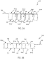
- the at least one member connected to control arm 302, whether functional as stalk stompers 304A, 304B, and 304C and/or chopper curtains 306A, 306B, 306C, and 306D, of the adjustable assembly according to the present disclosure can take any suitable shape. Examples of such shapes include, but are not limited to, quadrilateral shapes, such as squares, rectangles, trapezoids, rhomboids, and the like. In an exemplary aspect, and as best shown in Figures 3A and 3B , each of the plurality of stalk stompers 304A, 304B, and 304C and each of the plurality of chopper curtains 306A, 306B, 306C, and 306D are substantially rectangular in shape. In certain embodiments according to the present disclosure, each of the plurality of stalk stompers 304A, 304B, and 304C can include a planar upper portion 308 and a curved lower portion 310.
- the at least one member connected to control arm 302, whether functional as stalk stompers 304A, 304B, and 304C and/or chopper curtains 306A, 306B, 306C, and 306D, of the adjustable assemblies according to the present disclosure can be of any suitable dimension.
- each member when the at least one member connected to control arm 302 are quadrilateral in shape, each member can be of any suitable length and width. Examples of suitable widths, include, but are not limited to, any width from about 5 inches to 30 inches or from about 10 inches to 20 inches. In certain embodiments according to the present disclosure, a suitable width of a member that is quadrilateral in shape is from about 12 inches to 14 inches.
- a longitudinal length (L1) of each of the plurality of stalk stompers 304A, 304B, and 304C is greater than a longitudinal length (L2) of each of the plurality of chopper curtains 306A, 306B, 306C, and 306D.
- the at least one member connected to control arm 302, whether functional as stalk stompers 304A, 304B, and 304C and/or chopper curtains 306A, 306B, 306C, and 306D, of the adjustable assemblies according to the present disclosure can be formed from any suitable material.
- suitable materials include, but are not limited to, steel and lightweight materials, such as a high density polymers, fiberglass reinforced plastics (e.g., glass-filled nylon), elastomers, composites, ultra-high molecular weight polyethylene, and the like, or any combination thereof.
- the at least one member connected to control arm 302, whether functional as stalk stompers 304A, 304B, and 304C and/or chopper curtains 306A, 306B, 306C, and 306D, of the adjustable assembly according to the present disclosure can include a biasing member 312, which biases the at least one member connected to control arm 302 toward the ground.
- biasing members include, but are not limited to, torsion springs, polymer torsion blocks, gas shocks, and leaf springs.
- the control arm 302 is configured to receive a plurality of torsion springs as the biasing members. As depicted therein, each of the plurality of biasing members 312 biases each of the plurality of stalk stompers 304A, 304B, and 304C, respectively, toward the ground.
- header 200 is operatively connected to combine 102.
- Tool bar 208 is operatively connected to header 200.
- Mounting members 210 are fastened onto tool bar 208, e.g., with the aid of fasteners 216.
- Control arm 302 is operatively connected to tool bar 208 via mounting members 210.
- Control arm 302 is secured onto mounting members 210 and the plurality of members configured to knock down/flatten plant/crop stalks and/or shield the agricultural harvester from flying debris, e.g., stalk stompers 304A, 304B, and 304C and chopper curtains 306A, 306B, 306C, and 306D are operatively connected to control arm 302 via fasteners 212 such that the plurality of stalk stompers 304A, 304B, and 304C and chopper curtains 306A, 306B, 306C, and 306D are aligned linearly adjacent to one another in a single plane or substantially in a single plane in an alternating fashion on control arm 302.
- flying debris e.g., stalk stompers 304A, 304B, and 304C and chopper curtains 306A, 306B, 306C, and 306D are operatively connected to control arm 302 via fasteners 212 such that the plurality of stalk s
- the at least one members connected to control arm 302, whether functional as stalk stompers 304A, 304B, and 304C and/or chopper curtains 306A, 306B, 306C, and 306D, can also be arranged randomly, or in any suitable pattern or group, and in any plane or orientation relative to each other, on control arm 302.
- Biasing members 312 are mounted on control arm 302 and operatively connected to each of the plurality of stalk stompers 304A, 304B, and 304C for biasing the stalk stompers toward the ground.
- adjustable assembly 300 is configured such that control arm 302 is rotatable about its longitudinal axis 314.
- control arm 302 can be rotated between a work position, wherein, for example, lower portions 310 of the plurality of stalk stompers 304A, 304B, and 304C can come in contact with the stalks or the ground, and a storage position, wherein lower portions 310 of the plurality of stalk stompers 304A, 304B, and 304C can be spaced away from and the stalks and the ground at any desired angle.
- This adjustment of the angle of the plurality stalk stompers 304A, 304B, and 304C provides for a tensioning system to achieve a desired force to flatten/knock down stalks during harvesting operations. Adjustment of the desired angle can be achieved either by manually rotating control arm 302 with the aid of handle 314 or, alternatively, via actuator 318 operatively engaged with control arm 302 for adjusting the rotational position of control arm 302.
- the height of tool bar 202 can be raised or lowered relative to the ground to adjust the height of the plurality of members, e.g., stalk stompers 304A, 304B, and 304C and chopper curtains 306A, 306B, 306C, and 306D, based on different cut heights of the stalks.
- the plurality of members e.g., stalk stompers 304A, 304B, and 304C and chopper curtains 306A, 306B, 306C, and 306D
- the adjustable assemblies according to the present invention can be automated and/or self-adjusting with regard to the distance of the plurality of members configured to knock down/flatten plant/crop stalks and/or shield the agricultural harvester from flying debris, e.g., stalk stompers 304A, 304B, and 304C and chopper curtains 306A, 306B, 306C, and 306D, from the ground or stalk cut heights.
- flying debris e.g., stalk stompers 304A, 304B, and 304C and chopper curtains 306A, 306B, 306C, and 306D
- the adjustable assemblies according to the present disclosure can further include one or more sensors that detect proximity to the ground and/or plant/crop stalks and/or detect pressure against the at least one member configured to knock down plant stalks and/or to shield the agricultural harvester from flying debris and that are in operative communication with a control unit, which, in turn, is in operative communication with an actuator 318 to control a height, angle, and/or other position of the adjustable assembly, as necessary to optimize harvesting operations based on, e.g., crop type, crop height, and/or terrain conditions.
- the control unit is pre-programmed to respond based on the data input received from the one or more sensors.
- control unit is operated manually, e.g., by the operator in the cab of the combine harvester, based on the data received from the one or more sensors.
- adjustable assemblies according to the present disclosure can be programmed and/or operated, for example, from the cab of the combine harvester by the operator, such that the members configured to knock down plant stalks and/or to shield the agricultural harvester from flying debris are automatically rotatably deployed downwards while the combine harvester is performing harvesting operations and retracted upwards when the combine harvester is stationary or moving in reverse or when the header is being transported or stored.
- the adjustable assemblies according to present disclosure can be modular.
- the adjustable assemblies according to present disclosure can be independently attached to tool bar 208, operated (e.g., rotatably raised into a storage position and rotatably lowered into a working position), and removed from tool bar 208 as discrete segments 500A and 500B of rotating control arms 302 to which is connected at least one member configured to knock down plant stalks and/or to shield the agricultural harvester from flying debris (e.g., a plurality of stalk stompers 304A, 304B, and 304C and/or chopper curtains 306A, 306B, 306C, and 306D).
- flying debris e.g., a plurality of stalk stompers 304A, 304B, and 304C and/or chopper curtains 306A, 306B, 306C, and 306D.
- the orientation of a first sub-plurality (e.g., module) of members of the plurality of members configured to knock down plant stalks and/or to shield the agricultural harvester from flying debris connected to the control arm 302 is adjustable independent of the orientation of a second module of these members.
- This independent movement of each module of adjustable assemblies can be achieved by any suitable mechanism, including, for example, by rotors 502A and 502B.
- such first and second (or third, etc.) modules of members configured to knock down plant stalks and/or to shield the agricultural harvester from flying debris can be removably connectable to the control arm 302 independent of each other.
- the primary purpose of the plurality of stalk stompers 304A, 304B, and 304C is to flatten/knock down crop stalks (e.g., corn stalks) after the crop (e.g., ears of corn) has been removed.
- crop stalks e.g., corn stalks
- the plurality of stalks stompers 304A, 304B, and 304C also serve to effectively block the flying debris generated during harvesting operations in the same manner as the plurality of chopper curtains 306A, 306B, 306C, and 306D, e.g., by effectively forming a blocking wall.
- the plurality of stalk stompers 304A, 304B, and 304C in conjunction with the plurality of chopper curtains 304A, 304B, 304C, and 304D, also assists in containing the sucrose spray spattered by corn stalks during the harvesting operations.
- Headers comprising the various embodiments of the of the present invention provide numerous advantages over conventional headers equipped with either stalk stompers or chopper curtains alone or with both stalk stompers and chopper curtains individually attached to the header as separate components.
- the adjustable assemblies according to the present disclosure prevent damage to components of agricultural harvesters by flattening/knocking down standing corn stalks and blocking flying debris generated during harvesting operations. Additionally, by configuring the adjustable assemblies according to the present invention such that the stalk stompers 304A, 304B, and 304C and chopper curtains 306A, 306B, 306C, and 306D are alternated along the control arm 302 in the same plane reduces the complexity involved in positioning these tools along the tool bar.
- the stalk stompers of the adjustable assemblies according to the present disclosure can be formed from lightweight materials, so that the overall weight of the adjustable assemblies is substantially less than the total weight of an equivalent plurality of conventional stalk stompers and chopper curtains, which makes the adjustable assemblies of the present disclosure easier to use, reposition, and remove, as well as mitigating the risk of soil compaction.
- the adjustable assemblies according to the present invention also allow for movement from a work position to a storage position and back without removing any components from the header and at a single time rather than needing to adjust these components individually.
- this retractability of the adjustable assemblies according to the present disclosure into a storage position is advantageous when placing the header on a trailer for transport or on the ground for storage, as it eliminates the need to remove the members configured to knock down plant stalks and/or to shield the agricultural harvester from flying debris from the adjustable assembly.
- the adjustable assemblies according to the present disclosure can also be configured to have multiple set points to accommodate different stalk stubble cut heights.
- the adjustable assemblies according to the present disclosure can be modular and, as such, can be either factory or customer installed. Overall, the design of the adjustable assemblies according to the present disclosure are more streamlined compared to conventional assemblies of conventional stalk stompers and chopper curtains, resulting in less weight, improved weight distribution and functionality, as well as mitigation of tripping hazards.
Landscapes
- Life Sciences & Earth Sciences (AREA)
- Environmental Sciences (AREA)
- Harvesting Machines For Specific Crops (AREA)
- Catching Or Destruction (AREA)
- Harvesting Machines For Root Crops (AREA)
- Harvester Elements (AREA)
Claims (12)
- Verstellbare Anordnung (300) zur Anbringung eines Vorsatzes (200) einer landwirtschaftlichen Erntemaschine (100), aufweisend:einen Steuerungsarm (302),mindestens ein Element, das mit dem Steuerungsarm (302) verbunden ist, um Pflanzenstoppel einzustampfen und/oder vor herumfliegenden Teilen zu schützen,wobei das mindestens eine Element eine Mehrzahl von Elementen aufweist, die mit dem Steuerungsarm (302) verbunden sind, und wobei jedes der Mehrzahl von Elementen benachbart zu einem anderen angeordnet und/oder im Wesentlichen in einer einzigen Ebene ausgerichtet ist,wobei der Steuerungsarm (302) eingerichtet ist, um die Ausrichtung des mindestens einen Elements relativ zum Untergrund einzustellen,wobei die verstellbare Anordnung (300) dadurch gekennzeichnet ist, dass:
die Mehrzahl von Elementen eine Mehrzahl von Stoppelstampfern (304A, 304B, 304C), die eingerichtet sind, um Pflanzenstoppel zu zerschlagen, und eine Mehrzahl von Häckselschürzen (306A, 306B, 306C), die eingerichtet sind, um vor herumfliegenden Teilen zu schützen, aufweist, oder die Mehrzahl von Elementen eine Mehrzahl von Stoppelstampfern (304A, 304B, 304C) und eine Mehrzahl von Häckselschürzen (306A, 306B, 306C) aufweist und jeder der Mehrzahl von Stoppelstampfern mit jeder der Mehrzahl von Häckselschürzen entlang einer Länge des Steuerungsarms abwechselnd angeordnet ist. - Verstellbare Anordnung nach Anspruch 1, wobei sich eine Längserstreckung eines seitlichen Rands eines der Mehrzahl von Elementen im Wesentlichen über die Länge einer gesamten Längserstreckung eines seitlichen Rands mindestens eines weiteren der Mehrzahl von Elementen erstreckt.
- Verstellbare Anordnung nach den Ansprüchen 1 bis 2, wobei eines der Mehrzahl von Elementen eine Längsabmessung (L1) hat, die größer als eine Längsabmessung (L2) von mindestens einem weiteren der Mehrzahl von Elementen ist und/oder ein Metall, ein Polymer mit hoher Dichte, ein Elastomer oder ein Verbundmaterial aufweist, und wobei ein weiteres der Mehrzahl von Elementen ein weiteres von Metall, Polymer mit hoher Dichte, Elastomer oder Verbundmaterial aufweist.
- Verstellbare Anordnung nach den Ansprüchen 1 bis 3, wobei die Ausrichtung einer ersten untergeordneten Mehrzahl von Elementen (500A) der Mehrzahl von Elementen, die mit dem Steuerungsarm (302) verbunden ist, unabhängig von der Ausrichtung einer zweiten untergeordneten Mehrzahl von Elementen (500B) der Mehrzahl von Elementen, die mit dem Steuerungsarm (302) verbunden ist, verstellbar ist.
- Verstellbare Anordnung nach Anspruch 4, wobei die erste und die zweite untergeordnete Mehrzahl von Elementen (500A) mit dem Steuerungsarm (302) unabhängig voneinander abnehmbar befestigbar sind.
- Verstellbare Anordnung nach den Ansprüchen 1 bis 5, wobei das mindestens eine Element mit dem Steuerungsarm (302) abnehmbar verbunden ist, oder wobei das mindestens eine Element eine vierseitige Form hat, oder wobei das mindestens eine Element einen ebenen oberen Abschnitt und einen gekrümmten unteren Abschnitt, der sich von dem ebenen oberen Abschnitt erstreckt, hat, oder wobei das mindestens eine Element zwischen einer ersten Position und einer zweiten Position, die von der ersten Position beabstandet ist, bewegbar ist.
- Verstellbare Anordnung nach den Ansprüchen 1 bis 6, wobei der Steuerungsarm (302) um seine Längsachse (320) drehbar ist, um die Ausrichtung des mindestens einen Elements relativ zum Untergrund einzustellen.
- Verstellbare Anordnung nach den Ansprüchen 1 bis 7, weiterhin aufweisend ein Vorspannelement (312), das das mindestens eine Element in Richtung auf den Untergrund vorspannt.
- Vorsatz (200) für eine landwirtschaftliche Erntemaschine (102), aufweisend die verstellbare Anordnung (300) nach den Ansprüchen 1 bis 8, wobei der Vorsatz (200) weiterhin einen Rahmen (202) mit einem Werkzeugbalken (208) aufweist, wobei der Steuerungsarm (302) der verstellbaren Anordnung (300) mit dem Werkzeugbalken (208) in Wirkverbindung steht.
- Vorsatz nach Anspruch 9, weiterhin aufweisend eine Betätigungseinrichtung, die mit dem Werkzeugbalken (208) zum Verstellen einer Translationsposition und/oder eines Winkels des Steuerungsarms (302) relativ zum Rahmen (202) in Wirkeingriff steht, oder weiterhin aufweisend eine Reiheneinheit, wobei das mindestens eine Element um ein unteres hinteres Ende der Reiheneinheit angeordnet ist.
- Landwirtschaftliche Erntemaschine (102) aufweisend den Vorsatz (200) nach den Ansprüchen 9 bis 10.
- Maschine aufweisend die verstellbare Anordnung (300) nach den Ansprüchen 1 bis 8, wobei die Maschine ausgewählt ist aus einer Gruppe bestehend aus Mähdreschern, Mähladern, Schlegelmähern, und Sichelmähern.
Applications Claiming Priority (1)
| Application Number | Priority Date | Filing Date | Title |
|---|---|---|---|
| US16/000,392 US10945371B2 (en) | 2018-06-05 | 2018-06-05 | Adjustable stalk stomper/chopper curtain assembly |
Publications (2)
| Publication Number | Publication Date |
|---|---|
| EP3578034A1 EP3578034A1 (de) | 2019-12-11 |
| EP3578034B1 true EP3578034B1 (de) | 2021-11-24 |
Family
ID=66690213
Family Applications (1)
| Application Number | Title | Priority Date | Filing Date |
|---|---|---|---|
| EP19177828.1A Active EP3578034B1 (de) | 2018-06-05 | 2019-06-03 | Verstellbare stoppelstampfer-/-häcksleranordnung |
Country Status (3)
| Country | Link |
|---|---|
| US (1) | US10945371B2 (de) |
| EP (1) | EP3578034B1 (de) |
| BR (1) | BR102019011487A2 (de) |
Families Citing this family (3)
| Publication number | Priority date | Publication date | Assignee | Title |
|---|---|---|---|---|
| USD908743S1 (en) * | 2019-05-09 | 2021-01-26 | Deere & Company | Panel of a harvester |
| DE102020119368B4 (de) * | 2020-07-22 | 2024-10-24 | Maschinenfabrik Bernard Krone GmbH & Co. KG | Schneidvorrichtung |
| US20250057065A1 (en) * | 2023-08-16 | 2025-02-20 | Cnh Industrial America Llc | Mower folding flail curtain |
Family Cites Families (40)
| Publication number | Priority date | Publication date | Assignee | Title |
|---|---|---|---|---|
| US3306015A (en) | 1964-08-04 | 1967-02-28 | Deere & Co | Safety curtain for farm implements |
| US3524307A (en) | 1967-02-28 | 1970-08-18 | Outboard Marine Corp | Rotating front guard for rotary lawnmowers |
| US3611681A (en) * | 1969-11-24 | 1971-10-12 | Int Harvester Co | Automatic unit height control for cotton harvester |
| CA987916A (en) | 1973-08-28 | 1976-04-27 | Canadian General Electric Company Limited | Footguard for rotary mower |
| US3982384A (en) * | 1975-02-21 | 1976-09-28 | Deere & Company | Row crop harvesting header |
| US4149361A (en) * | 1977-03-18 | 1979-04-17 | Deere & Company | Crop stubble masher for harvesting machine |
| US4466492A (en) * | 1981-11-09 | 1984-08-21 | Hiniker Company | Earthworking implement having spring biased arms |
| US5103624A (en) * | 1991-01-03 | 1992-04-14 | Marshall James W | Method and means for sweeping stalks from furrows onto ridges and shredding same |
| US5960618A (en) | 1997-01-09 | 1999-10-05 | Case Corporation | Row unit crop guide for harvesting multiple rows |
| US6539697B2 (en) * | 2001-02-22 | 2003-04-01 | Carl A. Burk | Apparatus and method for knocking down and crushing farm crop residue |
| DE20116343U1 (de) * | 2001-10-05 | 2001-12-20 | FAE ITALIA S.r.l., Fonto, Trento | Zerkleinerungsmaschine |
| US7373767B2 (en) | 2002-03-15 | 2008-05-20 | Marion Calmer | Corn head row unit |
| DE10242796A1 (de) | 2002-09-14 | 2004-03-18 | Maschinenfabrik Kemper Gmbh & Co. Kg | Erntegerät zur Ernte stängelartiger Pflanzen |
| HU229564B1 (en) * | 2007-01-26 | 2014-02-28 | Optigep Kft | Harvest adapter equipped with stalk crusher for cereals, mainly for sunflower |
| US7913480B2 (en) | 2008-09-23 | 2011-03-29 | Deere & Company | Row unit for an agricultural harvester |
| US7874134B1 (en) | 2009-07-17 | 2011-01-25 | Deere & Company | Converting a corn head row unit for harvesting corn stalks in addition to ears |
| US8171707B2 (en) * | 2010-01-25 | 2012-05-08 | Kitchel Enterprises, Llc | Corn stalk rollers |
| US20130061569A1 (en) * | 2010-11-03 | 2013-03-14 | Dean J. McClenathen | Device for flattening corn stalk stubbles |
| US8567167B2 (en) * | 2011-07-19 | 2013-10-29 | Kenneth E. Shoup | Quick connect/disconnect coupling for a stalk stomper |
| US8858110B2 (en) * | 2011-07-19 | 2014-10-14 | Kenneth E. Shoup | Quick connect/disconnect coupling for a stalk stomper |
| US8418432B2 (en) * | 2011-07-19 | 2013-04-16 | Kenneth E. Shoup | Quick connect/disconnect coupling for a stalk stomper |
| GB201112453D0 (en) * | 2011-07-20 | 2011-08-31 | Cnh Belgium Nv | Header assembly for a harvesting machine |
| DE102011051981A1 (de) | 2011-07-20 | 2013-01-24 | Cnh Belgium Nv | Modulares landwirtschaftliches Schneidwerk für eine Arbeitsmaschine |
| US8806846B2 (en) * | 2011-07-22 | 2014-08-19 | Lankota Group, Inc. | Stem deflector |
| US20130174529A1 (en) * | 2012-01-11 | 2013-07-11 | Lankota Group, Inc. | Stem Deflector Mount |
| US20130177348A1 (en) * | 2012-01-11 | 2013-07-11 | Lankota Group, Inc. | Stem deflector mount |
| US20140151073A1 (en) * | 2012-06-12 | 2014-06-05 | Titan International, Inc. | Stalk Folding and Breaking Device |
| DE102012108708B4 (de) * | 2012-09-17 | 2015-02-05 | Thomas Reiter | Erntegutaufnehmer |
| US8979106B2 (en) | 2012-11-12 | 2015-03-17 | Shoup Manufacturing Company | Tire protection mount |
| DE102013004438B3 (de) * | 2013-03-15 | 2014-03-13 | Wilhelm Lohaus | Maiserntevorrichtung |
| DE102013011272A1 (de) | 2013-07-05 | 2015-01-08 | Baß Antriebstechnik GmbH | Landwirtschaftliches Gerät und Verfahren zur Bearbeitung von Pflanzenstoppeln |
| US9730374B2 (en) | 2014-01-17 | 2017-08-15 | May-Wes Mfg. | Dual-position quick-connect mount and adjustably tensioned stalk stomper |
| US20150250098A1 (en) | 2014-03-04 | 2015-09-10 | Deere & Company | Stalk Breaker for a Corn Head |
| US9861036B2 (en) * | 2014-07-15 | 2018-01-09 | Cnh Industrial America Llc | Skid shoe for a header of an agricultural harvester |
| US9538709B2 (en) * | 2014-08-15 | 2017-01-10 | Kuhn North America, Inc. | Merger and pick-up header for a merger having an adjustable skid shoe |
| US20160066504A1 (en) | 2014-09-05 | 2016-03-10 | Michael Holman | Crop Stubble Flattening and Slicing Apparatus |
| US10231379B2 (en) * | 2014-12-30 | 2019-03-19 | Agco Corporation | Easy mount stalk stomper |
| US9743587B2 (en) * | 2014-12-30 | 2017-08-29 | Agco Corporation | Breakaway stalk stomper for corn header |
| CA2894100A1 (en) | 2015-06-11 | 2016-12-11 | Dave Dietrich | Harvesting apparatus for inter-seeded corps |
| EP3272199B1 (de) * | 2016-07-20 | 2019-09-25 | Deere & Company | Mulchgerät zur bearbeitung von auf einem feld stehenden pflanzenstümpfen |
-
2018
- 2018-06-05 US US16/000,392 patent/US10945371B2/en active Active
-
2019
- 2019-06-03 EP EP19177828.1A patent/EP3578034B1/de active Active
- 2019-06-04 BR BR102019011487A patent/BR102019011487A2/pt active Search and Examination
Also Published As
| Publication number | Publication date |
|---|---|
| BR102019011487A2 (pt) | 2019-12-10 |
| US10945371B2 (en) | 2021-03-16 |
| EP3578034A1 (de) | 2019-12-11 |
| US20190364736A1 (en) | 2019-12-05 |
Similar Documents
| Publication | Publication Date | Title |
|---|---|---|
| EP3469878B1 (de) | Rollzentrum für erntevorsatzrahmensteuerungsarmen | |
| US9861036B2 (en) | Skid shoe for a header of an agricultural harvester | |
| EP2734031B1 (de) | Kopfanordnung für eine erntemaschine | |
| US10398080B2 (en) | Mulching device for processing plant stubble on a field | |
| EP3258771B1 (de) | Einstellvorrichtung für haube und reihenteiler für eine landwirtschaftliche erntemaschine | |
| EP3578034B1 (de) | Verstellbare stoppelstampfer-/-häcksleranordnung | |
| US20200084968A1 (en) | Arrangement for controlling the height and/or incline of a combine header for harvesting thin-stemmed crops | |
| EP2993967B1 (de) | Abdeckung für die schneideanordnung eines vorsatzes einer landwirtschaftlichen maschine | |
| US7975458B1 (en) | Control system for a crop harvesting header | |
| US20240315173A1 (en) | Cam track adjustment assembly for a harvesting reel | |
| US10638664B2 (en) | Tool bar mounted folding wing mower apparatus | |
| EP3434097B1 (de) | Halmteiler für den erntevorsatz einer landwirtschaftlichen erntemaschine mit mehreren erntehaspeln | |
| US20090272090A1 (en) | Flexible tall crop pusher | |
| US20030110752A1 (en) | Guard for crop pick up apparatus | |
| US4199927A (en) | Combine reel weed shield | |
| US8312700B2 (en) | Tine assembly | |
| EP0558437B1 (de) | Mähmaschine für Gewächs | |
| EP3069595B1 (de) | Vorsatz für eine landwirtschaftliche erntemaschine mit doppeltem schneidwerk | |
| EP0432318B1 (de) | Universelles Ernte-Zusatzgerät für Mähdrescher | |
| CN109923999B (zh) | 具有处理立于田地上的植物茬杆用的覆盖装置的收割附件 | |
| EP3695704B1 (de) | Laufradkonditionierer mit einer zinkenvorrichtung mit begrenzter seitlicher bewegung | |
| US20120210691A1 (en) | Bell Knife for Rotary Mower | |
| US6662539B1 (en) | Crop harvesting machine with side discharge directed rearward | |
| CA1227044A (en) | Pickup attachment for harvesting machines | |
| AU2014202792A1 (en) | Harvesting cam reel with convertible transport mode |
Legal Events
| Date | Code | Title | Description |
|---|---|---|---|
| PUAI | Public reference made under article 153(3) epc to a published international application that has entered the european phase |
Free format text: ORIGINAL CODE: 0009012 |
|
| STAA | Information on the status of an ep patent application or granted ep patent |
Free format text: STATUS: THE APPLICATION HAS BEEN PUBLISHED |
|
| AK | Designated contracting states |
Kind code of ref document: A1 Designated state(s): AL AT BE BG CH CY CZ DE DK EE ES FI FR GB GR HR HU IE IS IT LI LT LU LV MC MK MT NL NO PL PT RO RS SE SI SK SM TR |
|
| AX | Request for extension of the european patent |
Extension state: BA ME |
|
| STAA | Information on the status of an ep patent application or granted ep patent |
Free format text: STATUS: REQUEST FOR EXAMINATION WAS MADE |
|
| 17P | Request for examination filed |
Effective date: 20200612 |
|
| RBV | Designated contracting states (corrected) |
Designated state(s): AL AT BE BG CH CY CZ DE DK EE ES FI FR GB GR HR HU IE IS IT LI LT LU LV MC MK MT NL NO PL PT RO RS SE SI SK SM TR |
|
| GRAP | Despatch of communication of intention to grant a patent |
Free format text: ORIGINAL CODE: EPIDOSNIGR1 |
|
| STAA | Information on the status of an ep patent application or granted ep patent |
Free format text: STATUS: GRANT OF PATENT IS INTENDED |
|
| INTG | Intention to grant announced |
Effective date: 20210610 |
|
| GRAS | Grant fee paid |
Free format text: ORIGINAL CODE: EPIDOSNIGR3 |
|
| GRAA | (expected) grant |
Free format text: ORIGINAL CODE: 0009210 |
|
| STAA | Information on the status of an ep patent application or granted ep patent |
Free format text: STATUS: THE PATENT HAS BEEN GRANTED |
|
| AK | Designated contracting states |
Kind code of ref document: B1 Designated state(s): AL AT BE BG CH CY CZ DE DK EE ES FI FR GB GR HR HU IE IS IT LI LT LU LV MC MK MT NL NO PL PT RO RS SE SI SK SM TR |
|
| REG | Reference to a national code |
Ref country code: GB Ref legal event code: FG4D |
|
| REG | Reference to a national code |
Ref country code: AT Ref legal event code: REF Ref document number: 1449123 Country of ref document: AT Kind code of ref document: T Effective date: 20211215 |
|
| REG | Reference to a national code |
Ref country code: DE Ref legal event code: R096 Ref document number: 602019009459 Country of ref document: DE |
|
| REG | Reference to a national code |
Ref country code: IE Ref legal event code: FG4D |
|
| REG | Reference to a national code |
Ref country code: LT Ref legal event code: MG9D |
|
| REG | Reference to a national code |
Ref country code: NL Ref legal event code: MP Effective date: 20211124 |
|
| REG | Reference to a national code |
Ref country code: AT Ref legal event code: MK05 Ref document number: 1449123 Country of ref document: AT Kind code of ref document: T Effective date: 20211124 |
|
| PG25 | Lapsed in a contracting state [announced via postgrant information from national office to epo] |
Ref country code: RS Free format text: LAPSE BECAUSE OF FAILURE TO SUBMIT A TRANSLATION OF THE DESCRIPTION OR TO PAY THE FEE WITHIN THE PRESCRIBED TIME-LIMIT Effective date: 20211124 Ref country code: LT Free format text: LAPSE BECAUSE OF FAILURE TO SUBMIT A TRANSLATION OF THE DESCRIPTION OR TO PAY THE FEE WITHIN THE PRESCRIBED TIME-LIMIT Effective date: 20211124 Ref country code: FI Free format text: LAPSE BECAUSE OF FAILURE TO SUBMIT A TRANSLATION OF THE DESCRIPTION OR TO PAY THE FEE WITHIN THE PRESCRIBED TIME-LIMIT Effective date: 20211124 Ref country code: BG Free format text: LAPSE BECAUSE OF FAILURE TO SUBMIT A TRANSLATION OF THE DESCRIPTION OR TO PAY THE FEE WITHIN THE PRESCRIBED TIME-LIMIT Effective date: 20220224 Ref country code: AT Free format text: LAPSE BECAUSE OF FAILURE TO SUBMIT A TRANSLATION OF THE DESCRIPTION OR TO PAY THE FEE WITHIN THE PRESCRIBED TIME-LIMIT Effective date: 20211124 |
|
| PG25 | Lapsed in a contracting state [announced via postgrant information from national office to epo] |
Ref country code: IS Free format text: LAPSE BECAUSE OF FAILURE TO SUBMIT A TRANSLATION OF THE DESCRIPTION OR TO PAY THE FEE WITHIN THE PRESCRIBED TIME-LIMIT Effective date: 20220324 Ref country code: SE Free format text: LAPSE BECAUSE OF FAILURE TO SUBMIT A TRANSLATION OF THE DESCRIPTION OR TO PAY THE FEE WITHIN THE PRESCRIBED TIME-LIMIT Effective date: 20211124 Ref country code: PT Free format text: LAPSE BECAUSE OF FAILURE TO SUBMIT A TRANSLATION OF THE DESCRIPTION OR TO PAY THE FEE WITHIN THE PRESCRIBED TIME-LIMIT Effective date: 20220324 Ref country code: PL Free format text: LAPSE BECAUSE OF FAILURE TO SUBMIT A TRANSLATION OF THE DESCRIPTION OR TO PAY THE FEE WITHIN THE PRESCRIBED TIME-LIMIT Effective date: 20211124 Ref country code: NO Free format text: LAPSE BECAUSE OF FAILURE TO SUBMIT A TRANSLATION OF THE DESCRIPTION OR TO PAY THE FEE WITHIN THE PRESCRIBED TIME-LIMIT Effective date: 20220224 Ref country code: NL Free format text: LAPSE BECAUSE OF FAILURE TO SUBMIT A TRANSLATION OF THE DESCRIPTION OR TO PAY THE FEE WITHIN THE PRESCRIBED TIME-LIMIT Effective date: 20211124 Ref country code: LV Free format text: LAPSE BECAUSE OF FAILURE TO SUBMIT A TRANSLATION OF THE DESCRIPTION OR TO PAY THE FEE WITHIN THE PRESCRIBED TIME-LIMIT Effective date: 20211124 Ref country code: HR Free format text: LAPSE BECAUSE OF FAILURE TO SUBMIT A TRANSLATION OF THE DESCRIPTION OR TO PAY THE FEE WITHIN THE PRESCRIBED TIME-LIMIT Effective date: 20211124 Ref country code: GR Free format text: LAPSE BECAUSE OF FAILURE TO SUBMIT A TRANSLATION OF THE DESCRIPTION OR TO PAY THE FEE WITHIN THE PRESCRIBED TIME-LIMIT Effective date: 20220225 Ref country code: ES Free format text: LAPSE BECAUSE OF FAILURE TO SUBMIT A TRANSLATION OF THE DESCRIPTION OR TO PAY THE FEE WITHIN THE PRESCRIBED TIME-LIMIT Effective date: 20211124 |
|
| PG25 | Lapsed in a contracting state [announced via postgrant information from national office to epo] |
Ref country code: SM Free format text: LAPSE BECAUSE OF FAILURE TO SUBMIT A TRANSLATION OF THE DESCRIPTION OR TO PAY THE FEE WITHIN THE PRESCRIBED TIME-LIMIT Effective date: 20211124 Ref country code: SK Free format text: LAPSE BECAUSE OF FAILURE TO SUBMIT A TRANSLATION OF THE DESCRIPTION OR TO PAY THE FEE WITHIN THE PRESCRIBED TIME-LIMIT Effective date: 20211124 Ref country code: RO Free format text: LAPSE BECAUSE OF FAILURE TO SUBMIT A TRANSLATION OF THE DESCRIPTION OR TO PAY THE FEE WITHIN THE PRESCRIBED TIME-LIMIT Effective date: 20211124 Ref country code: EE Free format text: LAPSE BECAUSE OF FAILURE TO SUBMIT A TRANSLATION OF THE DESCRIPTION OR TO PAY THE FEE WITHIN THE PRESCRIBED TIME-LIMIT Effective date: 20211124 Ref country code: DK Free format text: LAPSE BECAUSE OF FAILURE TO SUBMIT A TRANSLATION OF THE DESCRIPTION OR TO PAY THE FEE WITHIN THE PRESCRIBED TIME-LIMIT Effective date: 20211124 Ref country code: CZ Free format text: LAPSE BECAUSE OF FAILURE TO SUBMIT A TRANSLATION OF THE DESCRIPTION OR TO PAY THE FEE WITHIN THE PRESCRIBED TIME-LIMIT Effective date: 20211124 |
|
| REG | Reference to a national code |
Ref country code: DE Ref legal event code: R097 Ref document number: 602019009459 Country of ref document: DE |
|
| PLBE | No opposition filed within time limit |
Free format text: ORIGINAL CODE: 0009261 |
|
| STAA | Information on the status of an ep patent application or granted ep patent |
Free format text: STATUS: NO OPPOSITION FILED WITHIN TIME LIMIT |
|
| PG25 | Lapsed in a contracting state [announced via postgrant information from national office to epo] |
Ref country code: AL Free format text: LAPSE BECAUSE OF FAILURE TO SUBMIT A TRANSLATION OF THE DESCRIPTION OR TO PAY THE FEE WITHIN THE PRESCRIBED TIME-LIMIT Effective date: 20211124 |
|
| 26N | No opposition filed |
Effective date: 20220825 |
|
| PG25 | Lapsed in a contracting state [announced via postgrant information from national office to epo] |
Ref country code: SI Free format text: LAPSE BECAUSE OF FAILURE TO SUBMIT A TRANSLATION OF THE DESCRIPTION OR TO PAY THE FEE WITHIN THE PRESCRIBED TIME-LIMIT Effective date: 20211124 |
|
| PG25 | Lapsed in a contracting state [announced via postgrant information from national office to epo] |
Ref country code: MC Free format text: LAPSE BECAUSE OF FAILURE TO SUBMIT A TRANSLATION OF THE DESCRIPTION OR TO PAY THE FEE WITHIN THE PRESCRIBED TIME-LIMIT Effective date: 20211124 |
|
| REG | Reference to a national code |
Ref country code: CH Ref legal event code: PL |
|
| REG | Reference to a national code |
Ref country code: BE Ref legal event code: MM Effective date: 20220630 |
|
| PG25 | Lapsed in a contracting state [announced via postgrant information from national office to epo] |
Ref country code: LU Free format text: LAPSE BECAUSE OF NON-PAYMENT OF DUE FEES Effective date: 20220603 Ref country code: LI Free format text: LAPSE BECAUSE OF NON-PAYMENT OF DUE FEES Effective date: 20220630 Ref country code: IE Free format text: LAPSE BECAUSE OF NON-PAYMENT OF DUE FEES Effective date: 20220603 Ref country code: CH Free format text: LAPSE BECAUSE OF NON-PAYMENT OF DUE FEES Effective date: 20220630 |
|
| PG25 | Lapsed in a contracting state [announced via postgrant information from national office to epo] |
Ref country code: BE Free format text: LAPSE BECAUSE OF NON-PAYMENT OF DUE FEES Effective date: 20220630 |
|
| PG25 | Lapsed in a contracting state [announced via postgrant information from national office to epo] |
Ref country code: MK Free format text: LAPSE BECAUSE OF FAILURE TO SUBMIT A TRANSLATION OF THE DESCRIPTION OR TO PAY THE FEE WITHIN THE PRESCRIBED TIME-LIMIT Effective date: 20211124 Ref country code: CY Free format text: LAPSE BECAUSE OF FAILURE TO SUBMIT A TRANSLATION OF THE DESCRIPTION OR TO PAY THE FEE WITHIN THE PRESCRIBED TIME-LIMIT Effective date: 20211124 |
|
| PG25 | Lapsed in a contracting state [announced via postgrant information from national office to epo] |
Ref country code: HU Free format text: LAPSE BECAUSE OF FAILURE TO SUBMIT A TRANSLATION OF THE DESCRIPTION OR TO PAY THE FEE WITHIN THE PRESCRIBED TIME-LIMIT; INVALID AB INITIO Effective date: 20190603 |
|
| PG25 | Lapsed in a contracting state [announced via postgrant information from national office to epo] |
Ref country code: TR Free format text: LAPSE BECAUSE OF FAILURE TO SUBMIT A TRANSLATION OF THE DESCRIPTION OR TO PAY THE FEE WITHIN THE PRESCRIBED TIME-LIMIT Effective date: 20211124 |
|
| PG25 | Lapsed in a contracting state [announced via postgrant information from national office to epo] |
Ref country code: MT Free format text: LAPSE BECAUSE OF FAILURE TO SUBMIT A TRANSLATION OF THE DESCRIPTION OR TO PAY THE FEE WITHIN THE PRESCRIBED TIME-LIMIT Effective date: 20211124 |
|
| PGFP | Annual fee paid to national office [announced via postgrant information from national office to epo] |
Ref country code: DE Payment date: 20250626 Year of fee payment: 7 |
|
| PGFP | Annual fee paid to national office [announced via postgrant information from national office to epo] |
Ref country code: GB Payment date: 20250617 Year of fee payment: 7 |
|
| PGFP | Annual fee paid to national office [announced via postgrant information from national office to epo] |
Ref country code: FR Payment date: 20250624 Year of fee payment: 7 |
|
| PGFP | Annual fee paid to national office [announced via postgrant information from national office to epo] |
Ref country code: IT Payment date: 20250623 Year of fee payment: 7 |