EP3577324B1 - Verfahren zum verdichten von in einem partikelfilter abgeschiedener asche durch zuführen eines niedertemperaturschmelzsalzes in diesen filter - Google Patents
Verfahren zum verdichten von in einem partikelfilter abgeschiedener asche durch zuführen eines niedertemperaturschmelzsalzes in diesen filter Download PDFInfo
- Publication number
- EP3577324B1 EP3577324B1 EP18747224.6A EP18747224A EP3577324B1 EP 3577324 B1 EP3577324 B1 EP 3577324B1 EP 18747224 A EP18747224 A EP 18747224A EP 3577324 B1 EP3577324 B1 EP 3577324B1
- Authority
- EP
- European Patent Office
- Prior art keywords
- low
- temperature melting
- particulate filter
- melting salt
- salt
- Prior art date
- Legal status (The legal status is an assumption and is not a legal conclusion. Google has not performed a legal analysis and makes no representation as to the accuracy of the status listed.)
- Active
Links
Images


Classifications
-
- F—MECHANICAL ENGINEERING; LIGHTING; HEATING; WEAPONS; BLASTING
- F01—MACHINES OR ENGINES IN GENERAL; ENGINE PLANTS IN GENERAL; STEAM ENGINES
- F01N—GAS-FLOW SILENCERS OR EXHAUST APPARATUS FOR MACHINES OR ENGINES IN GENERAL; GAS-FLOW SILENCERS OR EXHAUST APPARATUS FOR INTERNAL-COMBUSTION ENGINES
- F01N9/00—Electrical control of exhaust gas treating apparatus
-
- B—PERFORMING OPERATIONS; TRANSPORTING
- B01—PHYSICAL OR CHEMICAL PROCESSES OR APPARATUS IN GENERAL
- B01D—SEPARATION
- B01D46/00—Filters or filtering processes specially modified for separating dispersed particles from gases or vapours
- B01D46/02—Particle separators, e.g. dust precipitators, having hollow filters made of flexible material
- B01D46/04—Cleaning filters
-
- B—PERFORMING OPERATIONS; TRANSPORTING
- B01—PHYSICAL OR CHEMICAL PROCESSES OR APPARATUS IN GENERAL
- B01D—SEPARATION
- B01D46/00—Filters or filtering processes specially modified for separating dispersed particles from gases or vapours
- B01D46/66—Regeneration of the filtering material or filter elements inside the filter
-
- B—PERFORMING OPERATIONS; TRANSPORTING
- B01—PHYSICAL OR CHEMICAL PROCESSES OR APPARATUS IN GENERAL
- B01D—SEPARATION
- B01D46/00—Filters or filtering processes specially modified for separating dispersed particles from gases or vapours
- B01D46/66—Regeneration of the filtering material or filter elements inside the filter
- B01D46/80—Chemical processes for the removal of the retained particles, e.g. by burning
- B01D46/82—Chemical processes for the removal of the retained particles, e.g. by burning with catalysts
-
- F—MECHANICAL ENGINEERING; LIGHTING; HEATING; WEAPONS; BLASTING
- F01—MACHINES OR ENGINES IN GENERAL; ENGINE PLANTS IN GENERAL; STEAM ENGINES
- F01N—GAS-FLOW SILENCERS OR EXHAUST APPARATUS FOR MACHINES OR ENGINES IN GENERAL; GAS-FLOW SILENCERS OR EXHAUST APPARATUS FOR INTERNAL-COMBUSTION ENGINES
- F01N3/00—Exhaust or silencing apparatus having means for purifying, rendering innocuous, or otherwise treating exhaust
- F01N3/02—Exhaust or silencing apparatus having means for purifying, rendering innocuous, or otherwise treating exhaust for cooling, or for removing solid constituents of, exhaust
- F01N3/021—Exhaust or silencing apparatus having means for purifying, rendering innocuous, or otherwise treating exhaust for cooling, or for removing solid constituents of, exhaust by means of filters
-
- F—MECHANICAL ENGINEERING; LIGHTING; HEATING; WEAPONS; BLASTING
- F01—MACHINES OR ENGINES IN GENERAL; ENGINE PLANTS IN GENERAL; STEAM ENGINES
- F01N—GAS-FLOW SILENCERS OR EXHAUST APPARATUS FOR MACHINES OR ENGINES IN GENERAL; GAS-FLOW SILENCERS OR EXHAUST APPARATUS FOR INTERNAL-COMBUSTION ENGINES
- F01N3/00—Exhaust or silencing apparatus having means for purifying, rendering innocuous, or otherwise treating exhaust
- F01N3/02—Exhaust or silencing apparatus having means for purifying, rendering innocuous, or otherwise treating exhaust for cooling, or for removing solid constituents of, exhaust
- F01N3/021—Exhaust or silencing apparatus having means for purifying, rendering innocuous, or otherwise treating exhaust for cooling, or for removing solid constituents of, exhaust by means of filters
- F01N3/023—Exhaust or silencing apparatus having means for purifying, rendering innocuous, or otherwise treating exhaust for cooling, or for removing solid constituents of, exhaust by means of filters using means for regenerating the filters, e.g. by burning trapped particles
- F01N3/0232—Exhaust or silencing apparatus having means for purifying, rendering innocuous, or otherwise treating exhaust for cooling, or for removing solid constituents of, exhaust by means of filters using means for regenerating the filters, e.g. by burning trapped particles removing incombustible material from a particle filter, e.g. ash
-
- F—MECHANICAL ENGINEERING; LIGHTING; HEATING; WEAPONS; BLASTING
- F01—MACHINES OR ENGINES IN GENERAL; ENGINE PLANTS IN GENERAL; STEAM ENGINES
- F01N—GAS-FLOW SILENCERS OR EXHAUST APPARATUS FOR MACHINES OR ENGINES IN GENERAL; GAS-FLOW SILENCERS OR EXHAUST APPARATUS FOR INTERNAL-COMBUSTION ENGINES
- F01N9/00—Electrical control of exhaust gas treating apparatus
- F01N9/002—Electrical control of exhaust gas treating apparatus of filter regeneration
-
- B—PERFORMING OPERATIONS; TRANSPORTING
- B01—PHYSICAL OR CHEMICAL PROCESSES OR APPARATUS IN GENERAL
- B01D—SEPARATION
- B01D2279/00—Filters adapted for separating dispersed particles from gases or vapours specially modified for specific uses
- B01D2279/30—Filters adapted for separating dispersed particles from gases or vapours specially modified for specific uses for treatment of exhaust gases from IC Engines
-
- F—MECHANICAL ENGINEERING; LIGHTING; HEATING; WEAPONS; BLASTING
- F01—MACHINES OR ENGINES IN GENERAL; ENGINE PLANTS IN GENERAL; STEAM ENGINES
- F01N—GAS-FLOW SILENCERS OR EXHAUST APPARATUS FOR MACHINES OR ENGINES IN GENERAL; GAS-FLOW SILENCERS OR EXHAUST APPARATUS FOR INTERNAL-COMBUSTION ENGINES
- F01N2250/00—Combinations of different methods of purification
- F01N2250/14—Combinations of different methods of purification absorption or adsorption, and filtering
-
- F—MECHANICAL ENGINEERING; LIGHTING; HEATING; WEAPONS; BLASTING
- F01—MACHINES OR ENGINES IN GENERAL; ENGINE PLANTS IN GENERAL; STEAM ENGINES
- F01N—GAS-FLOW SILENCERS OR EXHAUST APPARATUS FOR MACHINES OR ENGINES IN GENERAL; GAS-FLOW SILENCERS OR EXHAUST APPARATUS FOR INTERNAL-COMBUSTION ENGINES
- F01N2430/00—Influencing exhaust purification, e.g. starting of catalytic reaction, filter regeneration, or the like, by controlling engine operating characteristics
- F01N2430/04—Influencing exhaust purification, e.g. starting of catalytic reaction, filter regeneration, or the like, by controlling engine operating characteristics by adding non-fuel substances to combustion air or fuel, e.g. additives
-
- F—MECHANICAL ENGINEERING; LIGHTING; HEATING; WEAPONS; BLASTING
- F01—MACHINES OR ENGINES IN GENERAL; ENGINE PLANTS IN GENERAL; STEAM ENGINES
- F01N—GAS-FLOW SILENCERS OR EXHAUST APPARATUS FOR MACHINES OR ENGINES IN GENERAL; GAS-FLOW SILENCERS OR EXHAUST APPARATUS FOR INTERNAL-COMBUSTION ENGINES
- F01N2550/00—Monitoring or diagnosing the deterioration of exhaust systems
- F01N2550/14—Systems for adding secondary air into exhaust
-
- F—MECHANICAL ENGINEERING; LIGHTING; HEATING; WEAPONS; BLASTING
- F01—MACHINES OR ENGINES IN GENERAL; ENGINE PLANTS IN GENERAL; STEAM ENGINES
- F01N—GAS-FLOW SILENCERS OR EXHAUST APPARATUS FOR MACHINES OR ENGINES IN GENERAL; GAS-FLOW SILENCERS OR EXHAUST APPARATUS FOR INTERNAL-COMBUSTION ENGINES
- F01N2610/00—Adding substances to exhaust gases
-
- F—MECHANICAL ENGINEERING; LIGHTING; HEATING; WEAPONS; BLASTING
- F01—MACHINES OR ENGINES IN GENERAL; ENGINE PLANTS IN GENERAL; STEAM ENGINES
- F01N—GAS-FLOW SILENCERS OR EXHAUST APPARATUS FOR MACHINES OR ENGINES IN GENERAL; GAS-FLOW SILENCERS OR EXHAUST APPARATUS FOR INTERNAL-COMBUSTION ENGINES
- F01N2610/00—Adding substances to exhaust gases
- F01N2610/01—Adding substances to exhaust gases the substance being catalytic material in liquid form
-
- F—MECHANICAL ENGINEERING; LIGHTING; HEATING; WEAPONS; BLASTING
- F01—MACHINES OR ENGINES IN GENERAL; ENGINE PLANTS IN GENERAL; STEAM ENGINES
- F01N—GAS-FLOW SILENCERS OR EXHAUST APPARATUS FOR MACHINES OR ENGINES IN GENERAL; GAS-FLOW SILENCERS OR EXHAUST APPARATUS FOR INTERNAL-COMBUSTION ENGINES
- F01N2610/00—Adding substances to exhaust gases
- F01N2610/12—Adding substances to exhaust gases the substance being in solid form, e.g. pellets or powder
-
- F—MECHANICAL ENGINEERING; LIGHTING; HEATING; WEAPONS; BLASTING
- F01—MACHINES OR ENGINES IN GENERAL; ENGINE PLANTS IN GENERAL; STEAM ENGINES
- F01N—GAS-FLOW SILENCERS OR EXHAUST APPARATUS FOR MACHINES OR ENGINES IN GENERAL; GAS-FLOW SILENCERS OR EXHAUST APPARATUS FOR INTERNAL-COMBUSTION ENGINES
- F01N2900/00—Details of electrical control or of the monitoring of the exhaust gas treating apparatus
- F01N2900/06—Parameters used for exhaust control or diagnosing
- F01N2900/16—Parameters used for exhaust control or diagnosing said parameters being related to the exhaust apparatus, e.g. particulate filter or catalyst
- F01N2900/1611—Particle filter ash amount
-
- Y—GENERAL TAGGING OF NEW TECHNOLOGICAL DEVELOPMENTS; GENERAL TAGGING OF CROSS-SECTIONAL TECHNOLOGIES SPANNING OVER SEVERAL SECTIONS OF THE IPC; TECHNICAL SUBJECTS COVERED BY FORMER USPC CROSS-REFERENCE ART COLLECTIONS [XRACs] AND DIGESTS
- Y02—TECHNOLOGIES OR APPLICATIONS FOR MITIGATION OR ADAPTATION AGAINST CLIMATE CHANGE
- Y02T—CLIMATE CHANGE MITIGATION TECHNOLOGIES RELATED TO TRANSPORTATION
- Y02T10/00—Road transport of goods or passengers
- Y02T10/10—Internal combustion engine [ICE] based vehicles
- Y02T10/40—Engine management systems
Definitions
- the present disclosure relates in general to methods of compacting ash deposited in a particulate filter for a vehicle exhaust gas system.
- the present disclosure further relates to engine systems and vehicles for implementing such methods.
- An internal combustion engine combusts a fuel and air mixture in order to generate a driving moment, which powers for example a heavy vehicle, such as a bus or truck.
- the combustion process generates exhaust gases which exit the engine and are transferred to an exhaust gas system.
- the exhaust gases from a lean diesel combustion engine mainly comprise nitrogen oxide gases (NO x ), carbon dioxide (CO 2 ), carbon monoxide (CO), water (H 2 O), hydrocarbon (HC), and particulates.
- the exhaust gas particulates comprise soot, i.e. carbon-rich particles resulting from the incomplete combustion of fuel, and ash, i.e. non-combustible inorganic matter deriving primarily from additives in the engine lubrication oil and impurities in the fuel.
- the exhaust gas system typically includes one or more particulate filters, for example a diesel particulate filter (DPF) such as a catalysed soot filter (CSF), in order to trap particulates in the exhaust gas.
- DPF diesel particulate filter
- CSF catalysed soot filter
- Additional catalysts may also be provided in the exhaust gas system, such as a diesel oxidation catalyst (DOC), a selective catalytic reduction (SCR) catalyst, and an ammonia slip catalyst (ASC).
- DOC diesel oxidation catalyst
- SCR selective catalytic reduction
- ASC ammonia slip catalyst
- the diesel particulate filter accumulates ash and soot particulate matter during operation, leading to clogging of the filter and increased exhaust back-pressure if not remedied.
- Combustible matter i.e. soot
- the particulate filter can be provided with a coating of an oxidation catalyst (catalysed DPF, cDPF) and/or have a DOC arranged upstream.
- oxidation catalyst catalysed DPF, cDPF
- DOC oxidation catalyst
- These catalysts oxidise NO to NO 2 , which is a highly effective oxidant for soot.
- the presence of these catalysts therefore enables the oxidation of soot at relatively low temperatures, allowing continuous regeneration of the filter under normal operating conditions. This is known as passive regeneration.
- the incombustible matter commonly referred to as ash
- ash is accumulated as a low-density deposit in the inlet channels of a wall-flow particulate filter. If left unremedied, the accumulated ash will fill the particulate filter and cause excessive back-pressure. Accumulated ash cannot easily be removed from the particulate filter, without replacing the filter. There are however methods of compacting and redistributing the ash further back in the flow path through the filter, thus reducing the pressure drop across the filter and allowing a longer service life prior to replacing the filter.
- the density and distribution of ash is affected by flow and temperature conditions in the particulate filter. At conditions used in active regeneration, the ash is sintered, leading to a much more compact ash and redistributing the ash deeper within the inlet channels of the particulate filter. Such compaction and redistribution may be achieved either by regulating the engine to provide higher exhaust temperatures, or by providing fuel to the diesel oxidation catalyst, which in an exothermic reaction oxidises the fuel, thus raising the exhaust temperature downstream of the oxidation catalyst.
- US20030101717 discloses a diesel particle filter having an impaction surface such that adhesion of non-combustible ash particles occurs on this surface only with such binding forces that the ash particles can be removed from the impaction surface with a fluid and/or by vibrational effects.
- An additive functioning to lower the adhesion of the ash particles to one another and/or to the impaction-side surface of the diesel particle filter may be added to one or more of a fuel, a motor oil, an intake air and/or an exhaust gas flow, during the operation of the diesel engine.
- EP 1 411 106 is related to the use of a fuel additive for protecting and improving operation of combustion exhaust after treatment systems.
- the additive contains one or more manganese compounds.
- CN 105 802 713 discloses a lubricating composition
- a base oil comprising calcium chloride.
- the inventors of the present invention have identified shortcomings in the prior art. They have recognised that the low density packing and unfavourable distribution of ash in the particulate filter leads to premature plugging of the filter. This leads to the need to either over-dimension filters or to frequently service/replace them. Compaction and redistribution can assist in reducing the pressure drop over the particulate filter, but attainment of such compaction and redistribution requires subjecting the particulate filter to high temperatures. Subjecting the particulate filter to such high temperatures requires excessive energy expenditure and may cause wear or even premature failure of exhaust system components. Prior art methods for addressing ash plugging may require specially coated or treated surfaces and are not applicable to regular particulate filters lacking such surfaces.
- the particulate filter By bringing the particulate filter to a compaction temperature it is meant that the temperature of the filter is brought to a temperature equal to or above a minimum compaction temperature required to achieve compaction of the mixture of the ash and the low-temperature melting salt.
- the particulate filter may be brought to a compaction temperature by routine operation of the vehicle.
- the particle filter may be brought to a compaction temperature by active measures to heat the particulate filter, such as raising the temperature of the exhaust stream or utilizing heating elements in the housing of the particulate filter.
- the step a) of providing a low-temperature melting salt to the particulate filter may be achieved by dosing the low-temperature melting salt to an engine oil, dosing the low-temperature melting salt to a fuel, dosing the low-temperature melting salt to an intake air, and/or dosing the low-temperature melting salt to the vehicle exhaust gas system upstream of the particulate filter. Therefore, there is an abundance of different means of delivering the low-temperature melting salt to the particulate filter, many of which do not necessarily require significant reengineering of the engine system components.
- the low-temperature melting salt may be dosed as a powder, a solid-in-solid dispersion, a solid-in-liquid dispersion or a molten salt. This allows delivery of the salt to the particulate filter in a convenient manner.
- the low-temperature melting salt may have a melting point of from 100 °C to 1000 °C. This is much lower than the principle component of ash deriving from lubricant oil, calcium sulfate (m.p. 1460 °C), and should ensure that compaction is obtained at temperatures much lower than is commonly the case.
- the low-temperature melting salt may comprise at least one cationic component and at least one anionic component, wherein the at least one cationic component may be lithium (Li + ), sodium (Na + ), potassium (K + ), rubidium (Rb + ), caesium (Cs + ), calcium (Ca 2+ ) or ammonium (NH 4 + ) ion, and the at least one anionic component may be fluoride (F - ), chloride (Cl - ), bromide (Br - ), iodide (I - ), nitrate (NO 3 - ), or sulfate (SO 4 2- ) ion.
- the low-temperature melting comprises alkali metal halide salts. Such alkali metal halides are cheap, abundant and readily available.
- the low-temperature melting salt may be provided to the particulate filter in an amount of from 0.2 weight% to 20 weight%, relative to the dry weight of uncompacted ash deposited in the particulate filter. This ensures sufficient salt to provide the desired compaction effect while avoiding over-deposition of inorganic matter on the particulate filter.
- the compaction temperature may be from 300 °C to 700 °C, preferably from 400 °C to 500 °C. Such temperatures may be low enough to avoid excessive thermal wear of exhaust system components.
- the present invention also concerns the use of a low-melting salt for compacting an ash deposited in a particulate filter for a vehicle exhaust gas system.
- the compaction temperature may be routinely achieved during normal operation of the vehicle.
- the low-temperature melting salt in the engine oil may comprise at least one cationic component and at least one anionic component, wherein the at least one cationic component is lithium (Li + ), sodium (Na + ), potassium (K + ), rubidium (Rb + ), caesium (Cs + ), calcium (Ca 2+ ) or ammonium (NH 4 + ) ion, and the at least one anionic component is fluoride (F - ), chloride (Cl - ), bromide (Br - ),iodide (I - ), nitrate (NO 3 - ), or sulfate (SO 4 2- ) ion.
- the low-temperature melting salt in the engine oil may comprise alkali metal halide salts. Such alkali metal halides are cheap, abundant and readily available.
- the solid matrix may be a controlled-release matrix arranged to controllably release the low-temperature melting salt when submerged in an engine oil at temperatures of 50 °C and over, preferably at temperatures of 100 °C and over. This allows for an optimal concentration of the salt at all times whilst minimizing the need to periodically provide additives to the engine oil.
- the low-temperature melting salt in the dosage product may comprise at least one cationic component and at least one anionic component, wherein the at least one cationic component is lithium (Li + ), sodium (Na + ), potassium (K + ), rubidium (Rb + ), caesium (Cs + ), calcium (Ca 2+ ) or ammonium (NH 4 + ) ion, and the at least one anionic component is fluoride (F - ), chloride (Cl - ), bromide (Br - ),iodide (I - ), nitrate (NO 3 - ), or sulfate (SO 4 2- ) ion.
- the low-temperature melting salt in the dosage product comprises alkali metal halide salts. Such alkali metal halides are cheap, abundant and readily available.
- an engine system for a vehicle according to the appended claims.
- the engine system comprises:
- an engine system with a salt dosing unit allows for a more precise dosing of the low temperature melting salt and permits the salt only to be dosed under specific circumstances, e.g. prior to an active regeneration of the particulate filter or when the pressure drop across the filter becomes excessively high.
- the salt dosing unit may be arranged to dose the low-temperature melting salt as a powder, a solid-in-solid dispersion, a solid-in-liquid dispersion or a molten salt.
- a variety of wellcharacterised and robust dosing technologies may be used.
- the objects of the invention are achieved by a vehicle comprising an engine oil, and/or a low-temperature melting salt dosage product and/or an engine system as disclosed herein.
- the present invention is based on the insight by the inventors that compaction and redistribution of ash in the particulate filter of a vehicle may be assisted by providing one or more auxiliary salts mixed in the ash.
- auxiliary salts have more favourable compaction and redistribution properties than typical motor ash, and aid the typical ash in compacting and redistributing within the particulate filter. This results in lower exhaust temperatures being required for compaction of the low-temperature melting salt/ash mixture, meaning that compaction may be achieved under milder conditions than typically required.
- the method of compacting deposited ash comprises the steps of:
- the auxiliary salts are low-temperature melting salts.
- low-temperature melting salt it is meant a salt that has a lower melting point than the inorganic materials and salts typically present in the ash.
- the primary constituent of motor ash is typically calcium sulfate, which has a melting point of 1460 °C.
- the low-temperature melting salts of the present invention may have a melting point of about 1000 °C or lower, such as lower than about 900 °C or lower than about 800 °C.
- the low-temperature melting salt may comprise at least one cationic component and at least one anionic component.
- the at least one cationic component may be selected from lithium (Li + ), sodium (Na + ), potassium (K + ), rubidium (Rb + ), caesium (Cs + ), calcium (Ca 2+ ) or ammonium (NH 4 + ) ions.
- the at least one anionic component may be selected from fluoride (F - ), chloride (Cl - ), bromide (Br - ),iodide (I - ), nitrate (NO 3 - ), or sulfate (SO 4 2- ) ions.
- the low-temperature melting salt may comprise further cations or anions other than those listed above.
- a proton (H + ) may be present as a cation in salts having a divalent anion, e.g. NaHSO 4 .
- Suitable salts include, but are not limited to lithium fluoride, lithium chloride, lithium bromide, lithium iodide, lithium nitrate, lithium sulfate, sodium fluoride, sodium chloride, sodium bromide, sodium iodide, sodium nitrate, sodium sulfate, potassium fluoride, potassium chloride, potassium bromide, potassium iodide, potassium nitrate, potassium sulfate, rubidium fluoride, rubidium chloride, rubidium bromide, rubidium iodide, rubidium nitrate, rubidium sulfate, caesium fluoride, caesium chloride, caesium bromide, caesium iodide, caesium nitrate, caesium sulfate, calcium fluoride, calcium chloride, calcium bromide, calcium iodide, calcium nitrate, calcium sulfate, ammonium fluoride, ammoni
- the low-temperature melting salt assists in the compaction and redistribution of the typical ash inorganic matter. This may be due to a number of effects.
- the low-melting salt may act as a sintering aid to the ash inorganic matter, thus causing the ash to sinter at lower exhaust temperatures.
- the low-melting salt may form an eutectic composition with the ash, thus lowering the overall melting point of the ash/salt composition.
- the low-temperature melting salt may assist in the conglomeration and/or packing of the ash.
- the low-temperature melting salt may be added to non-compacted ash in quantities of from about 0.2 weight% to about 20 weight%, relative to the dry weight of uncompacted ash deposited in the particulate filter.
- the low-temperature melting salt is added in quantities sufficient to induce compaction and redistribution of the ash without loading the particulate filter with unnecessarily large quantities of inorganic materials.
- the temperature of the particulate filter is brought to a compacting temperature in order to compact and redistribute the deposited ash/salt mixture.
- compaction temperature it is meant any temperature equal to or above the minimum compaction temperature.
- the minimum compaction temperature is the lowest temperature at which the compaction of the ash/salt mixture occurs on the particulate filter.
- the particulate filter may be brought to a compaction temperature by routine operation of the vehicle, without any particular measures to raise the temperature of the particulate filter.
- the particulate filter may be brought to a compaction temperature by heat-generating measures taken during regular passive regeneration of the particulate filter, irrespective of the ash loading of the filter. If relatively high compaction temperatures are required, active measures to raise the temperature of the particulate filter may be performed.
- the step of increasing the temperature may vary. For example, if the low-temperature melting salt is dosed discretely, for example using a salt dosing unit located in the exhaust system, then the temperature increase may be timed to coincide or correspond with the dosing of the low-temperature melting salt. If the low-temperature melting salt is dosed continuously, for example by dispersion in the engine oil, then the temperature increase may be initiated by another parameter, e.g. the temperature may be increased periodically, or whenever the pressure drop across the particulate filter increases above a threshold level.
- the temperature of the particulate filter may be raised using any means known in the art. For example, if a diesel oxidation catalyst (DOC) is arranged upstream of the particulate filter, or if the particulate filter is itself catalysed (e.g. a catalysed soot filter, CSF), then the temperature may be raised by exothermic oxidation of hydrocarbons in the exhaust stream. Hydrocarbons may be introduced into the exhaust stream by a specific injector in the exhaust system or by controlling the timing of the engine valves to allow uncombusted fuel to pass through to the exhaust stream. The temperature in the exhaust system may also be raised by controlling the engine to produce a hotter exhaust stream. The particulate filter may also be specifically heated, for example by incorporation of a heating element in the housing of the filter.
- DOC diesel oxidation catalyst
- the compaction temperature required to achieve sufficient compacting of the low-temperature melting salt/ash mixture may depend on a number of factors including the nature of the low-temperature melting salt, the exhaust volume flow, the duration that the particulate filter is subjected to the compaction temperature, the salt-to-ash ratio and the ash loading of the particulate filter.
- the minimum compaction temperature may be from about 300 °C to about 700 °C.
- the minimum compaction temperature may be from about 300 °C to about 600 °C, such as from about 400 °C to 500 °C.
- the typical temperature required for active regeneration of a particulate filter, whereby soot is removed using oxygen as the primary oxidant is 600 °C.
- the minimum compaction temperature is below the temperature required for active regeneration.
- the low-temperature melting salt may be introduced into any material flow that ultimately leads to the particulate filter.
- this includes introduction into the fuel, the intake air, the engine lubrication oil or the exhaust gases. Combinations of such means of depositing the low-temperature melting salt on the particulate filter may also be used.
- An engine lubrication oil comprising the low-temperature melting salt may be manufactured.
- particles of the low-temperature melting salt may be dispersed in a lubrication oil used for lubrication of an engine, such as a multi-grade synthetic oil.
- the low-temperature melting salt may be present in the oil in amounts of from about 10 ppm to about 1000 ppm by mass.
- a discrete dosage form may be prepared for addition to engine oils that already are commercially available.
- This low-temperature melting salt dosage product may take the form of a low-temperature melting salt dispersed in a solid matrix, such as a wax.
- the matrix may dissolve upon submersion in the engine oil, thereby rapidly providing a dispersion of the low-temperature melting salt in the engine oil.
- the matrix solid may be a controlled-release matrix allowing for a slow, continuous release of low-temperature melting salt into the oil at the conditions prevailing in the engine lubricant system.
- Such a controlled-release matrix material may comprise a lipophilic solid such as a wax that has a melting point in excess of the temperature prevailing within the engine lubrication system.
- a lipophilic solid such as a wax that has a melting point in excess of the temperature prevailing within the engine lubrication system.
- thermostat waxes may be suitable as a controlled-release matrix. Erosion and/or dissolution of the matrix releases the low-temperature melting salt into the engine oil in a controlled fashion over an extended time period.
- the low-temperature melting salt may be provided dispersed in the fuel of the vehicle.
- a diesel fuel comprising dispersed low-temperature melting salt may be manufactured, or the low-temperature melting salt may be added as an additive to a commercially available fuel.
- An engine system of a vehicle may be adapted to provide for dosing of the low-temperature melting salt at one or more points in the system.
- the engine system of a vehicle typically comprises at least the following systems and/or components: an internal combustion engine; a fuel supply system; an air intake system; a lubrication system and an exhaust gas system. Any of the listed components and/or systems may be adapted to provide for dosing of the low-temperature melting salt. Depending on the nature of the salt used and the temperature prevailing in the relevant system and/or component, the low-temperature melting salt may be dosed in a variety of forms.
- salts having a melting point of lower than 200 °C such as a mixture of sodium, potassium and calcium nitrates having a melting point of 131 °C, may be dosed in a pure form as a molten salt.
- Salts having a higher melting point may be dosed as powders using a metering device, or may be dosed as aqueous solutions by injector.
- an injector may be arranged in the intake manifold of a vehicle in order to inject an aqueous solution of a low-temperature melting salt.
- An injector may be arranged in the exhaust conduit of a vehicle upstream of the particulate filter in order inject an aqueous solution of a low-temperature melting salt directly to the exhaust stream.
- a powder metering device may be arranged to provide low-temperature melting salt as a powder to the oil sump of a vehicle.
- a solids metering device may be arranged in conjunction with the oil sump of a vehicle in order to provide low-temperature melting salt as a powder to the engine oil.
- a powder metering device may be arranged in conjunction with the return line of a fuel common-rail in order to provide low-temperature melting salt as a powder to the fuel.
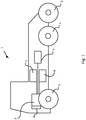
- Fig. 1 depicts a vehicle 1, here in the form of a truck, in a schematic side view.
- the vehicle may however be any other motor driven vehicle, for example a bus, a watercraft, or a passenger car.
- the vehicle comprises a combustion engine 2 which powers the vehicle's tractive wheels 3 via a gearbox (not shown) and a propeller shaft (not shown).
- the engine 2 is provided with an exhaust gas treatment system comprising a particulate filter 4.
- the engine 2 is powered by fuel supplied to it via a fuel system which comprises a fuel tank 5.
- An air intake system comprising an intake manifold 6 provides air to the combustion engine 2.
- An engine lubrication system 8 supplies lubricant to the moving parts of the engine 2.
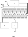
- Fig. 2 depicts schematically an engine system 10 according to the present invention.
- the engine system 10 comprises an internal combustion engine 2 having combustion cylinders 11.
- An intake manifold 6 provides air to the internal combustion engine 2, and a fuel common rail 12 supplies fuel to the cylinders 11 from fuel tank 5. Exhaust gases resulting from combustion of the fuel are collected by the exhaust manifold 14 and conveyed to particulate filter 4.
- a lubricant system 15 provides lubricant to the components of the engine 2.
- a salt dosing unit 16, here illustrated as an injector for injecting a salt solution, is arranged in the intake manifold 6 dosing of the low-temperature melting salt to the intake air. Salt supplied to the intake air manifold 6 will be conveyed via the combustion cylinders 11 and exhaust manifold 14 to the particulate filter 4.
- the salt will assist in compacting and redistributing any ash deposited in the particulate filter 4.
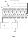
- Fig. 3 schematically depicts an engine system 10 similar to that of Fig. 2 .
- the salt dosing unit 16 is arranged in conjunction with the exhaust manifold 14.
- the engine components are therefore not exposed to the potentially corrosive salt, and the salt is not subjected to the highly oxidising conditions prevailing in the combustion cylinders 11.
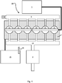
- Fig. 4 schematically depicts an engine system 10 similar to that of Figs. 2 and 3 .
- the salt dosing unit 16 is a powder feeder arranged in conjunction with the lubricant system 15.
- Fig. 5 depicts schematically a process flow chart for the method of compacting an ash deposited in a particulate filter according to the present invention.
- Step s501 denotes the start of the method.
- step s503 the low-temperature melting salt is provided to the particulate filter, for example using one of the means described above. In this manner, a mixture of ash and the low-temperature melting salt is formed in the particulate filter.
- step s505 the particulate filter is brought to a compaction temperature, for example using one of the means described above, thereby compacting the mixture of the ash and the low-temperature melting salt.
- Step s507 denotes the end of the method.
Landscapes
- Engineering & Computer Science (AREA)
- Chemical & Material Sciences (AREA)
- Combustion & Propulsion (AREA)
- Mechanical Engineering (AREA)
- General Engineering & Computer Science (AREA)
- Chemical Kinetics & Catalysis (AREA)
- Processes For Solid Components From Exhaust (AREA)
- Exhaust Gas After Treatment (AREA)
- Filtering Materials (AREA)
- Lubrication Details And Ventilation Of Internal Combustion Engines (AREA)
Claims (9)
- Verfahren zum Verdichten einer in einem Partikelfilter (4) für ein Fahrzeugabgassystem abgeschiedenen Asche, wobei das Verfahren die folgenden Schritte umfasst:a) Zuführen eines Niedertemperatur-Schmelzsalzes zu dem Partikelfilter (4), wodurch ein Gemisch aus der Asche und dem Niedertemperatur-Schmelzsalz gebildet wird; undb) Bringen des Partikelfilters (4) auf eine Verdichtungstemperatur, wodurch das Gemisch aus der Asche und dem Niedertemperatur-Schmelzsalz verdichtet wird,dadurch gekennzeichnet, dass das Niedertemperatur-Schmelzsalz ein Alkalimetallhalogenid ist.
- Verfahren nach Anspruch 1, wobei der Schritt a) des Zuführens eines Niedertemperatur-Schmelzsalzes zu dem Partikelfilter durch Dosieren des Niedertemperatur-Schmelzsalzes zu einem Motoröl, durch Dosieren des Niedertemperatur-Schmelzsalzes zu einem Kraftstoff, durch Dosieren des Niedertemperatur-Schmelzsalzes zu einer Ansaugluft und/oder durch Dosieren des Niedertemperatur-Schmelzsalzes zu dem Fahrzeugabgassystem stromaufwärts des Partikelfilters erreicht wird.
- Verfahren nach Anspruch 2, wobei das Niedertemperatur-Schmelzsalz als Pulver, als Feststoff-in-Feststoff-Dispersion, als Feststoff-in-Flüssigkeit-Dispersion oder als geschmolzenes Salz dosiert wird.
- Verfahren nach einem der vorhergehenden Ansprüche, wobei das Niedertemperatur-Schmelzsalz einen Schmelzpunkt von 100 °C bis 1000 °C aufweist.
- Verfahren nach einem der vorhergehenden Ansprüche, wobei das Niedertemperatur-Schmelzsalz dem Partikelfilter (4) in einer Menge von 0,2 Gew.-% bis 20 Gew.-%, bezogen auf das Trockengewicht der in dem Partikelfilter abgeschiedenen unverdichteten Asche, zugeführt wird.
- Verfahren nach einem der vorhergehenden Ansprüche, wobei der Partikelfilter auf eine Mindestverdichtungstemperatur von 300 °C bis 700 °C, vorzugsweise von 400 °C bis 500 °C, gebracht wird.
- Motorsystem (10) für ein Fahrzeug, wobei das Motorsystem umfasst:- einen Verbrennungsmotor (2), der so angeordnet ist, dass er durch Verbrennung eines Kraftstoffs in Ansaugluft betrieben wird, der so angeordnet ist, dass er mittels eines Motoröls geschmiert wird, und der so angeordnet ist, dass er bei der Verbrennung eines Kraftstoffs Abgase erzeugt;- ein Kraftstoffversorgungssystem, das so angeordnet ist, dass es den Kraftstoff zum Verbrennungsmotor befördert;- ein Lufteinlasssystem, das so angeordnet ist, dass es Ansaugluft zum Verbrennungsmotor befördert;- ein Schmiersystem, das so angeordnet ist, dass es das Motoröl zum Verbrennungsmotor befördert;- ein Abgassystem, das so angeordnet ist, dass es die Abgase des Verbrennungsmotors befördert, wobei das Abgassystem einen Partikelfilter (4) zum Auffangen von in den Abgasen dispergierter Asche und/oder Ruß umfasst; undwobei das Motorsystem ferner eine Salzdosiereinheit (16) umfasst, die so angeordnet ist, dass sie dem Kraftstoff und/oder dem Motoröl und/oder der Ansaugluft und/oder dem Abgassystem stromaufwärts des Partikelfilters ein Niedertemperatur-Schmelzsalz dosiert zuführt,
dadurch gekennzeichnet, dass das Niedertemperatur-Schmelzsalz ein Alkalimetallhalogenid ist. - Motorsystem nach Anspruch 7, wobei die Salzdosiereinheit (16) so angeordnet ist, dass sie das Niedertemperatur-Schmelzsalz als Pulver, als Feststoff-in-Feststoff-Dispersion, als Feststoff-in-Flüssigkeit-Dispersion oder als geschmolzenes Salz dosiert.
- Fahrzeug (1) mit einem Motorsystem (10) nach einem der Ansprüche 7-8.
Applications Claiming Priority (2)
| Application Number | Priority Date | Filing Date | Title |
|---|---|---|---|
| SE1750091A SE541936C2 (en) | 2017-02-03 | 2017-02-03 | Method of compacting ash deposited in a particulate filter by providing a low-temperature melting salt to said filter |
| PCT/SE2018/050049 WO2018143867A1 (en) | 2017-02-03 | 2018-01-23 | Method of compacting ash deposited in a particulate filter by providing a low-temperature melting salt to said filter |
Publications (3)
| Publication Number | Publication Date |
|---|---|
| EP3577324A1 EP3577324A1 (de) | 2019-12-11 |
| EP3577324A4 EP3577324A4 (de) | 2020-08-05 |
| EP3577324B1 true EP3577324B1 (de) | 2022-01-12 |
Family
ID=63039934
Family Applications (1)
| Application Number | Title | Priority Date | Filing Date |
|---|---|---|---|
| EP18747224.6A Active EP3577324B1 (de) | 2017-02-03 | 2018-01-23 | Verfahren zum verdichten von in einem partikelfilter abgeschiedener asche durch zuführen eines niedertemperaturschmelzsalzes in diesen filter |
Country Status (7)
| Country | Link |
|---|---|
| US (1) | US11098624B2 (de) |
| EP (1) | EP3577324B1 (de) |
| KR (1) | KR20190089065A (de) |
| CN (1) | CN110226023B (de) |
| BR (1) | BR112019013300A2 (de) |
| SE (1) | SE541936C2 (de) |
| WO (1) | WO2018143867A1 (de) |
Families Citing this family (1)
| Publication number | Priority date | Publication date | Assignee | Title |
|---|---|---|---|---|
| CN112354280B (zh) * | 2020-11-09 | 2022-01-18 | 淄博海益精细化工有限公司 | 一种带有球形滤芯的气通型高脱附率滤袋 |
Family Cites Families (37)
| Publication number | Priority date | Publication date | Assignee | Title |
|---|---|---|---|---|
| US3754074A (en) * | 1967-11-20 | 1973-08-21 | North American Rockwell | Removal of nitrogen oxides and other impurities from gaseous mixtures |
| US3634242A (en) * | 1968-12-18 | 1972-01-11 | Exxon Research Engineering Co | Fluorinated organic compounds as oil and distillate fuel additives |
| US3647358A (en) * | 1970-07-23 | 1972-03-07 | Anti Pollution Systems | Method of catalytically inducing oxidation of carbonaceous materials by the use of molten salts |
| US3899322A (en) * | 1972-06-20 | 1975-08-12 | Rockwell International Corp | Noble-type metal recovery process by use of molten salt bath |
| DE3232729A1 (de) * | 1982-09-03 | 1984-03-08 | Degussa Ag, 6000 Frankfurt | Verfahren zur herabsetzung der zuendtemperatur von aus dem abgas von dieselmotoren herausgefiltertem dieselruss |
| GB8705839D0 (en) | 1987-03-12 | 1987-04-15 | Exxon Chemical Patents Inc | Fuel compositions |
| ES2152282T3 (es) | 1988-12-06 | 2001-02-01 | Idemitsu Kosan Co | Aceite lubricante para refrigerador por compresion. |
| DE4041127A1 (de) | 1990-12-21 | 1992-02-20 | Daimler Benz Ag | Verfahren zur verringerung der schadstoffemission der verbrennungsabgase von dieselmotoren |
| GB9511266D0 (en) * | 1995-06-05 | 1995-08-02 | Exxon Chemical Patents Inc | Ester-free synthetic lubricating oils |
| WO1998003589A1 (en) * | 1996-07-24 | 1998-01-29 | Alliedsignal Inc. | Rigid copolyester blends mixed with a low molecular weight copolymer salt compatibilizer |
| ATE246239T1 (de) * | 1997-10-01 | 2003-08-15 | Unichema Chemie Bv | Komplexaster, diese enthaltende zusammensetzungen und ihre verwendung |
| KR100653817B1 (ko) | 1998-01-15 | 2006-12-05 | 이노스펙 리미티드 | 연료 첨가제 |
| US6013599A (en) * | 1998-07-15 | 2000-01-11 | Redem Corporation | Self-regenerating diesel exhaust particulate filter and material |
| EP1362905B1 (de) | 2000-08-22 | 2019-01-23 | Idemitsu Kosan Co., Ltd. | Verwendung einer ölzusammenstzung für dieselpartikelfilter |
| DE20117862U1 (de) | 2001-11-06 | 2003-04-10 | DaimlerChrysler AG, 70567 Stuttgart | Dieselpartikelfilter sowie Dieselmotor mit einem Dieselpartikelfilter |
| US6764664B2 (en) * | 2002-04-22 | 2004-07-20 | Delphi Technologies, Inc. | Catalyst for the combustion of diesel soot, methods for making the catalyst and methods of using the catalyst |
| US7297656B2 (en) * | 2002-04-22 | 2007-11-20 | Umicore Ag & Co. Kg | Particulate filter and method for treating soot |
| US20040074230A1 (en) | 2002-10-16 | 2004-04-22 | Guinther Gregory H. | Method of oxidizing soot and reducing soot accumulation in a diesel fuel combustion after treatment system |
| DE10359395A1 (de) * | 2003-12-18 | 2005-07-21 | Daimlerchrysler Ag | Verfahren zum Betreiben eines Partikelfilters im Abgasstrang einer Brennkraftmaschine eines Kraftfahrzeugs |
| WO2005077498A1 (en) * | 2004-02-04 | 2005-08-25 | Battelle Memorial Institute | Sulfur oxide adsorbents and emissions control |
| US20060205592A1 (en) * | 2005-03-14 | 2006-09-14 | Chien-Chung Chao | Catalytic adsorbents for mercury removal from flue gas and methods of manufacture therefor |
| EP2027371B1 (de) * | 2006-06-15 | 2019-12-04 | Dinex Finland Oy | Beschichtung für teilchenfilter |
| US20080311380A1 (en) * | 2007-06-12 | 2008-12-18 | Ajjer Llc | High refractive index materials and composites thereof |
| US9782748B2 (en) * | 2008-08-08 | 2017-10-10 | The University Of Toledo | Synthesis of polymeric ionic liquids using a photochemical polymerization process |
| US9500158B1 (en) * | 2009-03-02 | 2016-11-22 | Michael Anthony | Thermal engine for operation with noncombustible fuels |
| JP2013500152A (ja) * | 2009-07-29 | 2013-01-07 | コモンウェルス サイエンティフィック アンド インダストリアル リサーチ オーガニゼイション | イオン性液体 |
| DE102010020757A1 (de) * | 2010-05-17 | 2011-11-17 | Schaeffler Technologies Gmbh & Co. Kg | Verfahren zur Ermittlung einer Viskositäts-Kenngröße eines Motoröls sowie Steuereinrichtung zur elektronischen Motorsteuerung |
| US20130004586A1 (en) * | 2011-06-24 | 2013-01-03 | Vachon David J | Biologically Efficacious Compositions, Articles of Manufacture and Processes for Producing and/or Using Same |
| WO2013119718A1 (en) * | 2012-02-07 | 2013-08-15 | Jones Coyte | Treating waste streams with organic content |
| US9334772B2 (en) * | 2012-10-29 | 2016-05-10 | Massachusetts Institute Of Technology | Particulate filter control system and method |
| WO2014153570A2 (en) * | 2013-03-15 | 2014-09-25 | Transtar Group, Ltd | New and improved system for processing various chemicals and materials |
| US10530011B1 (en) * | 2014-07-21 | 2020-01-07 | Imprint Energy, Inc. | Electrochemical cells and metal salt-based electrolytes |
| US20160047284A1 (en) * | 2014-08-12 | 2016-02-18 | Luke J. Turgeon | Apparatus and Method for Preventing and Removing Carbon Deposits |
| JP2018507396A (ja) * | 2014-12-29 | 2018-03-15 | テラパワー, エルエルシー | 核物質処理 |
| SE539615C2 (en) * | 2016-02-11 | 2017-10-17 | Scania Cv Ab | An engine system lubricated by means of a lubrication oil that forms ammonia-soluble ash when combusted and a vehicle corprising the engine system |
| CN105802713A (zh) * | 2016-04-08 | 2016-07-27 | 苏州捷德瑞精密机械有限公司 | 一种耐低温润滑油及其制备方法 |
| WO2018227081A1 (en) * | 2017-06-09 | 2018-12-13 | Massachusetts Institute Of Technology | Carbon dioxide removal using lithium borate |
-
2017
- 2017-02-03 SE SE1750091A patent/SE541936C2/en unknown
-
2018
- 2018-01-23 KR KR1020197019641A patent/KR20190089065A/ko not_active Ceased
- 2018-01-23 EP EP18747224.6A patent/EP3577324B1/de active Active
- 2018-01-23 US US16/477,313 patent/US11098624B2/en active Active
- 2018-01-23 BR BR112019013300A patent/BR112019013300A2/pt not_active Application Discontinuation
- 2018-01-23 WO PCT/SE2018/050049 patent/WO2018143867A1/en not_active Ceased
- 2018-01-23 CN CN201880008674.2A patent/CN110226023B/zh active Active
Also Published As
| Publication number | Publication date |
|---|---|
| SE1750091A1 (sv) | 2018-08-04 |
| BR112019013300A2 (pt) | 2019-12-10 |
| WO2018143867A1 (en) | 2018-08-09 |
| CN110226023B (zh) | 2021-10-08 |
| US20200032684A1 (en) | 2020-01-30 |
| SE541936C2 (en) | 2020-01-07 |
| EP3577324A4 (de) | 2020-08-05 |
| EP3577324A1 (de) | 2019-12-11 |
| US11098624B2 (en) | 2021-08-24 |
| KR20190089065A (ko) | 2019-07-29 |
| CN110226023A (zh) | 2019-09-10 |
Similar Documents
| Publication | Publication Date | Title |
|---|---|---|
| DE69827803T2 (de) | VERMINDERUNG DES NOx AUSSTOSSES EINES MOTORS BEI MAXIMALER BRENNSTOFFEKONOMIE | |
| DE102013208042B4 (de) | Verfahren zum Steuern eines Betriebs eines Nachbehandlungssystems in einem Fahrzeug sowie entsprechend ausgebildetes Fahrzeug | |
| Khair | A review of diesel particulate filter technologies | |
| DE602004003354T2 (de) | Einen teilchenfilter und nox-absorber enthaltendes abgassystem für brennkraftmaschine mit magergemischverbrennung | |
| DE102010023820B4 (de) | Abgasbehandlungssystem für einen Dieselmotor, Verfahren zur Verwendung eines Abgasbehandlungssystems und Dieselmotor- und Abgasbehandlungssystem | |
| EP2644857B1 (de) | Verfahren zur Anwendung in Verbindung mit einer Abgasnachbehandlungsanlage | |
| SE1550228A1 (sv) | Förfarande och avgasbehandlingssystem för behandling av en avgasström | |
| RU2682203C1 (ru) | Система очистки выхлопных газов и способ для очистки потока выхлопных газов | |
| DE10156714B4 (de) | Reduktionsmittelzufuhrvorrichtung für Verbrennungsmotor | |
| DE102009006404B3 (de) | Diesel-Oxidationskatalysator mit guter Tieftemperaturaktivität | |
| RU2696654C1 (ru) | Способ и система для очистки потока выхлопных газов | |
| AT521448B1 (de) | Verfahren und Ottomotoranordnung mit verbesserter Partikelfilterung II | |
| RU2464428C2 (ru) | Избирательный впрыск катализатора окисления с учетом температуры | |
| KR102502788B1 (ko) | 가용성 염기성 금속 카르보네이트를 포함하는 배기 가스 오염 방지 유체, 이의 제조 방법, 및 내부-연소 엔진을 위한 이의 용도 | |
| US11098624B2 (en) | Method of compacting ash deposited in a particulate filter by providing a low-temperature melting salt to said filter | |
| US9675919B2 (en) | Method to enhance the ash storage capacity of a particulate filter | |
| WO2020000009A1 (de) | Verfahren und ottomotoranordnung mit einer verbesserten partikelfilterung i | |
| DE102016102436A1 (de) | Harnstoffzusatzsteuereinheit und Lerneinheit | |
| DE602004002347T2 (de) | Verfahren und Vorrichtung zur Reinigung von Abgasen einer Brennkraftmaschine | |
| DE102018119047A1 (de) | Verfahren zur überwachung und regenerierung von selektiven katalytischen reduktionsfiltervorrichtungen | |
| DE60210631T2 (de) | Verfahren zur Regenerierung einer Abgasfiltervorrichtung für Dieselmotoren und Vorrichtung dafür | |
| EP1520964B1 (de) | Abgasstrang und Verfahren zur Regenerierung eines Russfilters | |
| AT521749A1 (de) | Verfahren und Ottomotoranordnung mit einer verbesserten Abgasnachbehandlung durch eine Oxidationskatalysator-Beschichtung | |
| PL243930B1 (pl) | Sposób regeneracji filtra cząstek stałych | |
| DE102005022046A1 (de) | Abgasreinigungsanlage für Verbrennungsmotoren und Verfahren zur Abgasreinigung |
Legal Events
| Date | Code | Title | Description |
|---|---|---|---|
| STAA | Information on the status of an ep patent application or granted ep patent |
Free format text: STATUS: THE INTERNATIONAL PUBLICATION HAS BEEN MADE |
|
| PUAI | Public reference made under article 153(3) epc to a published international application that has entered the european phase |
Free format text: ORIGINAL CODE: 0009012 |
|
| STAA | Information on the status of an ep patent application or granted ep patent |
Free format text: STATUS: REQUEST FOR EXAMINATION WAS MADE |
|
| 17P | Request for examination filed |
Effective date: 20190903 |
|
| AK | Designated contracting states |
Kind code of ref document: A1 Designated state(s): AL AT BE BG CH CY CZ DE DK EE ES FI FR GB GR HR HU IE IS IT LI LT LU LV MC MK MT NL NO PL PT RO RS SE SI SK SM TR |
|
| AX | Request for extension of the european patent |
Extension state: BA ME |
|
| RIN1 | Information on inventor provided before grant (corrected) |
Inventor name: REGALI, FRANCESCO Inventor name: RAYMAND, DAVID Inventor name: ERIKSSON, HENRIK Inventor name: NYLEN, ULF Inventor name: BERGER, MATTIAS Inventor name: CARLSSON, JOEL |
|
| DAV | Request for validation of the european patent (deleted) | ||
| DAX | Request for extension of the european patent (deleted) | ||
| A4 | Supplementary search report drawn up and despatched |
Effective date: 20200702 |
|
| RIC1 | Information provided on ipc code assigned before grant |
Ipc: F01N 3/02 20060101AFI20200626BHEP Ipc: F01N 9/00 20060101ALI20200626BHEP Ipc: B01D 46/04 20060101ALI20200626BHEP |
|
| STAA | Information on the status of an ep patent application or granted ep patent |
Free format text: STATUS: EXAMINATION IS IN PROGRESS |
|
| RAP3 | Party data changed (applicant data changed or rights of an application transferred) |
Owner name: SCANIA CV AB |
|
| 17Q | First examination report despatched |
Effective date: 20210423 |
|
| GRAP | Despatch of communication of intention to grant a patent |
Free format text: ORIGINAL CODE: EPIDOSNIGR1 |
|
| STAA | Information on the status of an ep patent application or granted ep patent |
Free format text: STATUS: GRANT OF PATENT IS INTENDED |
|
| INTG | Intention to grant announced |
Effective date: 20210927 |
|
| GRAS | Grant fee paid |
Free format text: ORIGINAL CODE: EPIDOSNIGR3 |
|
| GRAA | (expected) grant |
Free format text: ORIGINAL CODE: 0009210 |
|
| STAA | Information on the status of an ep patent application or granted ep patent |
Free format text: STATUS: THE PATENT HAS BEEN GRANTED |
|
| AK | Designated contracting states |
Kind code of ref document: B1 Designated state(s): AL AT BE BG CH CY CZ DE DK EE ES FI FR GB GR HR HU IE IS IT LI LT LU LV MC MK MT NL NO PL PT RO RS SE SI SK SM TR |
|
| REG | Reference to a national code |
Ref country code: GB Ref legal event code: FG4D |
|
| REG | Reference to a national code |
Ref country code: CH Ref legal event code: EP |
|
| REG | Reference to a national code |
Ref country code: DE Ref legal event code: R096 Ref document number: 602018029538 Country of ref document: DE |
|
| REG | Reference to a national code |
Ref country code: IE Ref legal event code: FG4D |
|
| REG | Reference to a national code |
Ref country code: AT Ref legal event code: REF Ref document number: 1462528 Country of ref document: AT Kind code of ref document: T Effective date: 20220215 |
|
| REG | Reference to a national code |
Ref country code: LT Ref legal event code: MG9D |
|
| REG | Reference to a national code |
Ref country code: NL Ref legal event code: MP Effective date: 20220112 |
|
| REG | Reference to a national code |
Ref country code: AT Ref legal event code: MK05 Ref document number: 1462528 Country of ref document: AT Kind code of ref document: T Effective date: 20220112 |
|
| PG25 | Lapsed in a contracting state [announced via postgrant information from national office to epo] |
Ref country code: NL Free format text: LAPSE BECAUSE OF FAILURE TO SUBMIT A TRANSLATION OF THE DESCRIPTION OR TO PAY THE FEE WITHIN THE PRESCRIBED TIME-LIMIT Effective date: 20220112 |
|
| PG25 | Lapsed in a contracting state [announced via postgrant information from national office to epo] |
Ref country code: SE Free format text: LAPSE BECAUSE OF FAILURE TO SUBMIT A TRANSLATION OF THE DESCRIPTION OR TO PAY THE FEE WITHIN THE PRESCRIBED TIME-LIMIT Effective date: 20220112 Ref country code: RS Free format text: LAPSE BECAUSE OF FAILURE TO SUBMIT A TRANSLATION OF THE DESCRIPTION OR TO PAY THE FEE WITHIN THE PRESCRIBED TIME-LIMIT Effective date: 20220112 Ref country code: PT Free format text: LAPSE BECAUSE OF FAILURE TO SUBMIT A TRANSLATION OF THE DESCRIPTION OR TO PAY THE FEE WITHIN THE PRESCRIBED TIME-LIMIT Effective date: 20220512 Ref country code: NO Free format text: LAPSE BECAUSE OF FAILURE TO SUBMIT A TRANSLATION OF THE DESCRIPTION OR TO PAY THE FEE WITHIN THE PRESCRIBED TIME-LIMIT Effective date: 20220412 Ref country code: LT Free format text: LAPSE BECAUSE OF FAILURE TO SUBMIT A TRANSLATION OF THE DESCRIPTION OR TO PAY THE FEE WITHIN THE PRESCRIBED TIME-LIMIT Effective date: 20220112 Ref country code: HR Free format text: LAPSE BECAUSE OF FAILURE TO SUBMIT A TRANSLATION OF THE DESCRIPTION OR TO PAY THE FEE WITHIN THE PRESCRIBED TIME-LIMIT Effective date: 20220112 Ref country code: ES Free format text: LAPSE BECAUSE OF FAILURE TO SUBMIT A TRANSLATION OF THE DESCRIPTION OR TO PAY THE FEE WITHIN THE PRESCRIBED TIME-LIMIT Effective date: 20220112 Ref country code: BG Free format text: LAPSE BECAUSE OF FAILURE TO SUBMIT A TRANSLATION OF THE DESCRIPTION OR TO PAY THE FEE WITHIN THE PRESCRIBED TIME-LIMIT Effective date: 20220412 |
|
| PG25 | Lapsed in a contracting state [announced via postgrant information from national office to epo] |
Ref country code: PL Free format text: LAPSE BECAUSE OF FAILURE TO SUBMIT A TRANSLATION OF THE DESCRIPTION OR TO PAY THE FEE WITHIN THE PRESCRIBED TIME-LIMIT Effective date: 20220112 Ref country code: LV Free format text: LAPSE BECAUSE OF FAILURE TO SUBMIT A TRANSLATION OF THE DESCRIPTION OR TO PAY THE FEE WITHIN THE PRESCRIBED TIME-LIMIT Effective date: 20220112 Ref country code: GR Free format text: LAPSE BECAUSE OF FAILURE TO SUBMIT A TRANSLATION OF THE DESCRIPTION OR TO PAY THE FEE WITHIN THE PRESCRIBED TIME-LIMIT Effective date: 20220413 Ref country code: FI Free format text: LAPSE BECAUSE OF FAILURE TO SUBMIT A TRANSLATION OF THE DESCRIPTION OR TO PAY THE FEE WITHIN THE PRESCRIBED TIME-LIMIT Effective date: 20220112 Ref country code: AT Free format text: LAPSE BECAUSE OF FAILURE TO SUBMIT A TRANSLATION OF THE DESCRIPTION OR TO PAY THE FEE WITHIN THE PRESCRIBED TIME-LIMIT Effective date: 20220112 |
|
| REG | Reference to a national code |
Ref country code: CH Ref legal event code: PL |
|
| PG25 | Lapsed in a contracting state [announced via postgrant information from national office to epo] |
Ref country code: IS Free format text: LAPSE BECAUSE OF FAILURE TO SUBMIT A TRANSLATION OF THE DESCRIPTION OR TO PAY THE FEE WITHIN THE PRESCRIBED TIME-LIMIT Effective date: 20220512 |
|
| REG | Reference to a national code |
Ref country code: DE Ref legal event code: R097 Ref document number: 602018029538 Country of ref document: DE |
|
| PG25 | Lapsed in a contracting state [announced via postgrant information from national office to epo] |
Ref country code: SM Free format text: LAPSE BECAUSE OF FAILURE TO SUBMIT A TRANSLATION OF THE DESCRIPTION OR TO PAY THE FEE WITHIN THE PRESCRIBED TIME-LIMIT Effective date: 20220112 Ref country code: SK Free format text: LAPSE BECAUSE OF FAILURE TO SUBMIT A TRANSLATION OF THE DESCRIPTION OR TO PAY THE FEE WITHIN THE PRESCRIBED TIME-LIMIT Effective date: 20220112 Ref country code: RO Free format text: LAPSE BECAUSE OF FAILURE TO SUBMIT A TRANSLATION OF THE DESCRIPTION OR TO PAY THE FEE WITHIN THE PRESCRIBED TIME-LIMIT Effective date: 20220112 Ref country code: MC Free format text: LAPSE BECAUSE OF FAILURE TO SUBMIT A TRANSLATION OF THE DESCRIPTION OR TO PAY THE FEE WITHIN THE PRESCRIBED TIME-LIMIT Effective date: 20220112 Ref country code: LU Free format text: LAPSE BECAUSE OF NON-PAYMENT OF DUE FEES Effective date: 20220123 Ref country code: EE Free format text: LAPSE BECAUSE OF FAILURE TO SUBMIT A TRANSLATION OF THE DESCRIPTION OR TO PAY THE FEE WITHIN THE PRESCRIBED TIME-LIMIT Effective date: 20220112 Ref country code: DK Free format text: LAPSE BECAUSE OF FAILURE TO SUBMIT A TRANSLATION OF THE DESCRIPTION OR TO PAY THE FEE WITHIN THE PRESCRIBED TIME-LIMIT Effective date: 20220112 Ref country code: CZ Free format text: LAPSE BECAUSE OF FAILURE TO SUBMIT A TRANSLATION OF THE DESCRIPTION OR TO PAY THE FEE WITHIN THE PRESCRIBED TIME-LIMIT Effective date: 20220112 |
|
| PLBE | No opposition filed within time limit |
Free format text: ORIGINAL CODE: 0009261 |
|
| STAA | Information on the status of an ep patent application or granted ep patent |
Free format text: STATUS: NO OPPOSITION FILED WITHIN TIME LIMIT |
|
| PG25 | Lapsed in a contracting state [announced via postgrant information from national office to epo] |
Ref country code: AL Free format text: LAPSE BECAUSE OF FAILURE TO SUBMIT A TRANSLATION OF THE DESCRIPTION OR TO PAY THE FEE WITHIN THE PRESCRIBED TIME-LIMIT Effective date: 20220112 |
|
| 26N | No opposition filed |
Effective date: 20221013 |
|
| PG25 | Lapsed in a contracting state [announced via postgrant information from national office to epo] |
Ref country code: LI Free format text: LAPSE BECAUSE OF NON-PAYMENT OF DUE FEES Effective date: 20220131 Ref country code: CH Free format text: LAPSE BECAUSE OF NON-PAYMENT OF DUE FEES Effective date: 20220131 |
|
| PG25 | Lapsed in a contracting state [announced via postgrant information from national office to epo] |
Ref country code: IE Free format text: LAPSE BECAUSE OF NON-PAYMENT OF DUE FEES Effective date: 20220123 |
|
| PG25 | Lapsed in a contracting state [announced via postgrant information from national office to epo] |
Ref country code: SI Free format text: LAPSE BECAUSE OF FAILURE TO SUBMIT A TRANSLATION OF THE DESCRIPTION OR TO PAY THE FEE WITHIN THE PRESCRIBED TIME-LIMIT Effective date: 20220112 |
|
| P01 | Opt-out of the competence of the unified patent court (upc) registered |
Effective date: 20230518 |
|
| PG25 | Lapsed in a contracting state [announced via postgrant information from national office to epo] |
Ref country code: IT Free format text: LAPSE BECAUSE OF FAILURE TO SUBMIT A TRANSLATION OF THE DESCRIPTION OR TO PAY THE FEE WITHIN THE PRESCRIBED TIME-LIMIT Effective date: 20220112 |
|
| PG25 | Lapsed in a contracting state [announced via postgrant information from national office to epo] |
Ref country code: MK Free format text: LAPSE BECAUSE OF FAILURE TO SUBMIT A TRANSLATION OF THE DESCRIPTION OR TO PAY THE FEE WITHIN THE PRESCRIBED TIME-LIMIT Effective date: 20220112 Ref country code: CY Free format text: LAPSE BECAUSE OF FAILURE TO SUBMIT A TRANSLATION OF THE DESCRIPTION OR TO PAY THE FEE WITHIN THE PRESCRIBED TIME-LIMIT Effective date: 20220112 |
|
| PG25 | Lapsed in a contracting state [announced via postgrant information from national office to epo] |
Ref country code: HU Free format text: LAPSE BECAUSE OF FAILURE TO SUBMIT A TRANSLATION OF THE DESCRIPTION OR TO PAY THE FEE WITHIN THE PRESCRIBED TIME-LIMIT; INVALID AB INITIO Effective date: 20180123 |
|
| PG25 | Lapsed in a contracting state [announced via postgrant information from national office to epo] |
Ref country code: MT Free format text: LAPSE BECAUSE OF FAILURE TO SUBMIT A TRANSLATION OF THE DESCRIPTION OR TO PAY THE FEE WITHIN THE PRESCRIBED TIME-LIMIT Effective date: 20220112 |
|
| PG25 | Lapsed in a contracting state [announced via postgrant information from national office to epo] |
Ref country code: TR Free format text: LAPSE BECAUSE OF FAILURE TO SUBMIT A TRANSLATION OF THE DESCRIPTION OR TO PAY THE FEE WITHIN THE PRESCRIBED TIME-LIMIT Effective date: 20220112 |
|
| PGFP | Annual fee paid to national office [announced via postgrant information from national office to epo] |
Ref country code: GB Payment date: 20251204 Year of fee payment: 9 |
|
| PGFP | Annual fee paid to national office [announced via postgrant information from national office to epo] |
Ref country code: FR Payment date: 20251128 Year of fee payment: 9 |
|
| PGFP | Annual fee paid to national office [announced via postgrant information from national office to epo] |
Ref country code: DE Payment date: 20251203 Year of fee payment: 9 |
|
| PGFP | Annual fee paid to national office [announced via postgrant information from national office to epo] |
Ref country code: BE Payment date: 20260106 Year of fee payment: 9 |