EP3576440B1 - Adaptive mehrkanalige v2x-kommunikation - Google Patents
Adaptive mehrkanalige v2x-kommunikation Download PDFInfo
- Publication number
- EP3576440B1 EP3576440B1 EP19174961.3A EP19174961A EP3576440B1 EP 3576440 B1 EP3576440 B1 EP 3576440B1 EP 19174961 A EP19174961 A EP 19174961A EP 3576440 B1 EP3576440 B1 EP 3576440B1
- Authority
- EP
- European Patent Office
- Prior art keywords
- channel
- frequencies
- communication unit
- determining
- range
- Prior art date
- Legal status (The legal status is an assumption and is not a legal conclusion. Google has not performed a legal analysis and makes no representation as to the accuracy of the status listed.)
- Active
Links
Images






Classifications
-
- H—ELECTRICITY
- H04—ELECTRIC COMMUNICATION TECHNIQUE
- H04W—WIRELESS COMMUNICATION NETWORKS
- H04W72/00—Local resource management
- H04W72/04—Wireless resource allocation
- H04W72/044—Wireless resource allocation based on the type of the allocated resource
- H04W72/0453—Resources in frequency domain, e.g. a carrier in FDMA
-
- H—ELECTRICITY
- H04—ELECTRIC COMMUNICATION TECHNIQUE
- H04B—TRANSMISSION
- H04B17/00—Monitoring; Testing
- H04B17/30—Monitoring; Testing of propagation channels
- H04B17/309—Measuring or estimating channel quality parameters
- H04B17/336—Signal-to-interference ratio [SIR] or carrier-to-interference ratio [CIR]
-
- H—ELECTRICITY
- H04—ELECTRIC COMMUNICATION TECHNIQUE
- H04B—TRANSMISSION
- H04B17/00—Monitoring; Testing
- H04B17/30—Monitoring; Testing of propagation channels
- H04B17/382—Monitoring; Testing of propagation channels for resource allocation, admission control or handover
-
- H—ELECTRICITY
- H04—ELECTRIC COMMUNICATION TECHNIQUE
- H04W—WIRELESS COMMUNICATION NETWORKS
- H04W36/00—Hand-off or reselection arrangements
- H04W36/06—Reselecting a communication resource in the serving access point
-
- H—ELECTRICITY
- H04—ELECTRIC COMMUNICATION TECHNIQUE
- H04W—WIRELESS COMMUNICATION NETWORKS
- H04W4/00—Services specially adapted for wireless communication networks; Facilities therefor
- H04W4/30—Services specially adapted for particular environments, situations or purposes
- H04W4/40—Services specially adapted for particular environments, situations or purposes for vehicles, e.g. vehicle-to-pedestrians [V2P]
-
- H—ELECTRICITY
- H04—ELECTRIC COMMUNICATION TECHNIQUE
- H04W—WIRELESS COMMUNICATION NETWORKS
- H04W4/00—Services specially adapted for wireless communication networks; Facilities therefor
- H04W4/30—Services specially adapted for particular environments, situations or purposes
- H04W4/40—Services specially adapted for particular environments, situations or purposes for vehicles, e.g. vehicle-to-pedestrians [V2P]
- H04W4/44—Services specially adapted for particular environments, situations or purposes for vehicles, e.g. vehicle-to-pedestrians [V2P] for communication between vehicles and infrastructures, e.g. vehicle-to-cloud [V2C] or vehicle-to-home [V2H]
-
- H—ELECTRICITY
- H04—ELECTRIC COMMUNICATION TECHNIQUE
- H04W—WIRELESS COMMUNICATION NETWORKS
- H04W4/00—Services specially adapted for wireless communication networks; Facilities therefor
- H04W4/30—Services specially adapted for particular environments, situations or purposes
- H04W4/40—Services specially adapted for particular environments, situations or purposes for vehicles, e.g. vehicle-to-pedestrians [V2P]
- H04W4/46—Services specially adapted for particular environments, situations or purposes for vehicles, e.g. vehicle-to-pedestrians [V2P] for vehicle-to-vehicle communication [V2V]
-
- H—ELECTRICITY
- H04—ELECTRIC COMMUNICATION TECHNIQUE
- H04W—WIRELESS COMMUNICATION NETWORKS
- H04W72/00—Local resource management
- H04W72/50—Allocation or scheduling criteria for wireless resources
- H04W72/54—Allocation or scheduling criteria for wireless resources based on quality criteria
- H04W72/541—Allocation or scheduling criteria for wireless resources based on quality criteria using the level of interference
-
- H—ELECTRICITY
- H04—ELECTRIC COMMUNICATION TECHNIQUE
- H04W—WIRELESS COMMUNICATION NETWORKS
- H04W74/00—Wireless channel access
- H04W74/08—Non-scheduled access, e.g. ALOHA
- H04W74/0808—Non-scheduled access, e.g. ALOHA using carrier sensing, e.g. carrier sense multiple access [CSMA]
-
- H—ELECTRICITY
- H04—ELECTRIC COMMUNICATION TECHNIQUE
- H04W—WIRELESS COMMUNICATION NETWORKS
- H04W28/00—Network traffic management; Network resource management
- H04W28/02—Traffic management, e.g. flow control or congestion control
- H04W28/0231—Traffic management, e.g. flow control or congestion control based on communication conditions
- H04W28/0236—Traffic management, e.g. flow control or congestion control based on communication conditions radio quality, e.g. interference, losses or delay
-
- H—ELECTRICITY
- H04—ELECTRIC COMMUNICATION TECHNIQUE
- H04W—WIRELESS COMMUNICATION NETWORKS
- H04W4/00—Services specially adapted for wireless communication networks; Facilities therefor
- H04W4/90—Services for handling of emergency or hazardous situations, e.g. earthquake and tsunami warning systems [ETWS]
Definitions
- the present disclosure relates to wireless communications, and in particular to vehicular wireless communications.
- V2X communication provides wireless exchange of information between vehicles and external devices in a vehicular environment, such as other vehicles, network infrastructure devices, and pedestrians.
- V2X communication systems are typically designed to improve road safety, enhance the efficient flow of road traffic, and provide various types of information services to vehicles and other entities in a vehicular environment.
- Multi-channel Usage in Day 2 and beyond EU V2X Systems outlines options for channel usage in view of cross channel interference, and impacts from decentralized congestion control (DCC).
- DCC decentralized congestion control
- MCO multi-channel operation
- a method for transmitting, by a communication unit, channel allocation information for V2X (Vehicle-to-Everything) communications in a wireless communication.
- the method includes: determining a first channel, among a plurality of channels, that is utilized for V2X communications, the first channel defined by a first range of frequencies; determining state information that includes first state information regarding signal interference in the first channel; determining whether the state information satisfies at least one criteria; and based on a determination that the state information satisfies the at least one criteria: determining a second channel, among the plurality of channels, through which to transmit channel-reassignment information, the second channel defined by a second range of frequencies; determining a third range of frequencies, different from the first and second ranges of frequencies, to which to re- assign the V2X communications of the first channel; and transmitting, by the communication unit through the second channel to at least one vehicle, the channel-reassignment information regarding a change in
- implementations of this aspect include corresponding computer systems, apparatus, and computer programs recorded on one or more computer storage devices, each configured to cause at least one operably connected processor to perform the actions of the methods.
- determining the third range of frequencies, different from the first and second ranges of frequencies, to which to re-assign the V2X communications of the first channel may include: determining a third channel, among the plurality of channels, that defines the third range of frequencies to which to re-assign the V2X communications of the first channel, where the third range of frequencies is disjoint from the first range of frequencies of the first channel.
- determining the third range of frequencies, different from the first and second ranges of frequencies, to which to re-assign the V2X communications of the first channel may include: segmenting the first channel into at least two channel segments; and determining a first channel segment, among the at least two channel segments, that defines the third range of frequencies to which to re-assign the V2X communications of the first channel, where the third range of frequencies is a subset of the first range of frequencies of the first channel.
- determining the third range of frequencies, different from the first and second ranges of frequencies, to which to re-assign the V2X communications of the first channel may include: determining the third range of frequencies as a result of merging the first range of frequencies and a fourth range of frequencies.
- determining the third range of frequencies, different from the first and second ranges of frequencies, to which to re-assign the V2X communications of the first channel may include: monitoring, among the plurality of channels, a plurality of candidate channels and their respective signal-to-interference conditions; and determining, based on monitoring the plurality of candidate channels and their respective signal-to-interference conditions, a third channel having a signal-to-interference that is minimal among the plurality of candidate channels.
- determining the state information that may include the first state information regarding signal interference in the first channel may include: measuring a first ratio of time that the first channel is busy, as perceived by the communication unit; and determining a second ratio of time that the first channel is busy, as perceived by at least one vehicle other than the communication unit.
- measuring the first ratio of time that the first channel is busy, as perceived by the communication unit may include: measuring, at a transceiver of the communication unit, signal-to-interference in the first channel; and determining a first duration of time during which the signal-to-interference in the first channel measured at the transceiver of the communication unit exceeds a threshold.
- the state information may further include second state information regarding congestion around the communication unit, the second state information related to a number of sources of interference in the first channel.
- the second state information regarding congestion around the communication unit may include at least one of: (i) a number of messages that have been transmitted or received in the first channel by the communication unit or by at least one vehicle other than the communication unit, (ii) a number of neighboring vehicles around the communication unit, or (iii) sensing information that has been detected by the at least one vehicle other than the communication unit.
- determining that the state information satisfies the at least one criteria may include: determining, for the first state information, that the signal interference in the first channel exceeds a threshold interference criteria; and determining, for the second state information, that the congestion around the communication unit does not exceed a threshold congestion criteria.
- transmitting the channel-reassignment information by the communication unit through the second channel to the at least one vehicle may include: transmitting the channel-reassignment information, through the second channel, using an IEEE802.11p-based communication protocol.
- the communication unit may be configured to implement a Wireless Access in Vehicular Environments (WAVE) protocol, and the channel reassignment information may be configured as a WAVE Service Announcement (WSA) message.
- WAVE Wireless Access in Vehicular Environments
- WSA WAVE Service Announcement
- the channel reassignment information may include channel bandwidth information and interference information.
- the second channel may include a Control Channel (CCH) that has been assigned for the V2X communications.
- the second channel may be channel number 178 that has been assigned for the V2X communications.
- the plurality of channels may consist of seven channels, each having a bandwidth of 10 MHz, in a 5.9 GHz band of 5.855 GHz to 5.925 GHz.
- All or part of the features described throughout this application can be implemented as a computer program product including instructions that are stored on one or more non-transitory machine-readable storage media, and that are executable on one or more processing devices. All or part of the features described throughout this application can be implemented as an apparatus, method, or electronic system that can include one or more processing devices and memory to store executable instructions to implement the stated functions.
- AMCO adaptive multi-channel operation
- V2X vehicular communication system systems and techniques are disclosed herein that enable adaptive multi-channel operation (AMCO) in a wireless V2X vehicular communication system.
- the AMCO techniques provide improved resistance against interference and improve reliability in V2X communications by enabling dynamic and adaptive channel switching.
- channel switching information may be transmitted on a separate channel, indicating that V2X communications is to be switched from one channel to another lower-interference channel.
- the channel switching may be determined based on both signal interference and congestion information around a vehicle.
- V2X communications is configured to utilize a range of frequencies that is divided into multiple channels. Certain channels may be reserved exclusively for critical safety communications or public safety uses, while other channels may be used for non-safety V2X communications. In particular, critical safety communications are typically required to meet stringent reliability and latency requirements for the functioning of crucial vehicular applications, such as advanced driver assistance systems (ADAS).
- ADAS advanced driver assistance systems
- a V2X system may implement decentralized congestion control (DCC) to help ensure that a channel is not congested by an excess number of transmissions.
- DCC decentralized congestion control
- the DCC mechanism enables a V2X communication unit, such as an on-board unit (OBU) in a vehicle or a road side unit (RSU) installed in an infrastructure, to adapt its transmission behavior dynamically based on congestion in a channel.
- OBU on-board unit
- RSU road side unit
- a V2X communication unit may monitor a congestion level of a channel and may take actions to mitigate high congestion levels, such as reducing output power (to reduce interference for other vehicles), increasing inter-packet transmission time (to allow other vehicles more opportunity to transmit), drop packets, and/or increase transmission rate (to shorten the transmission duration and allowing other vehicles more time to transmit).
- reducing output power to reduce interference for other vehicles
- increasing inter-packet transmission time to allow other vehicles more opportunity to transmit
- drop packets and/or increase transmission rate (to shorten the transmission duration and allowing other vehicles more time to transmit).
- a communication unit may monitor a level of signal-to-interference in the channel.
- Information regarding the level of signal-to-interference in a channel may be determined by the communication unit itself through local interference measurements, or may be obtained from neighboring vehicles.
- V2X communication units may adapt their transmission behavior to help reduce channel congestion.
- DCC mechanisms rely on the cooperative behavior of communication units to help reduce overall congestion in the channel.
- DCC mechanisms that rely on signal-to-interference information alone may be less effective in scenarios where interference is caused by sources other than DCC-based communication units, such as interference caused by devices using non-DCC protocols or interference caused by environmental sources.
- communication units that adapt their transmission behavior according to such DCC mechanisms may be forced to throttle their transmissions and/or suffer increased errors, while the non-DCC source(s) of interference continue to cause interference unimpeded.
- DCC-based communication units that adapt their transmission behavior simply based on channel interference alone may suffer from extended periods of low-rate and/or high-latency communication.
- a non-DCC device such as a drone (or other unmanned aerial vehicle)
- a non-DCC device may be present in a vehicular environment, and may continuously transmit video with high transmission power. Consequently, nearby V2X devices that implement DCC mechanisms may sense a high level of interference in their respective channels, and throttle their transmissions (e.g., by reducing output power and/or increasing inter-packet delays) or accept a higher error rate (e.g., by increasing the transmission rate) accordingly. Meanwhile, the non-DCC drone would continue to transmit at a high transmission power, and thus force the nearby DCC-based V2X vehicles to wait for extended periods of time, potentially causing delays and/or errors in transmission of safety-critical information.
- Implementations disclosed herein mitigate such challenges by enabling DCC-based communication units to recognize whether a high level of interference is actually caused by high levels of traffic congestion on the road, or whether the interference is due to non-congestion reasons (e.g., a single source of interference).
- DCC-based communication units are enabled to proactively switch channels and re-assign their communications to a less-congested channel when appropriate.
- implementations disclosed herein enable a more flexible and dynamic DCC-based multi-channel operation (MCO) that is not necessarily limited to utilize fixed channel assignments, e.g., for critical safety communication.
- MCO multi-channel operation
- implementations disclosed herein enable more adaptive transmission of such safety information over different channels.
- important service announcements may be distributed over different channels, and thus help reduce congestion and delay.
- implementations disclosed herein may provide a communication environment that is more resistant to attacks by malicious users, as well as more resistant to interference caused by various types of sources.
- implementations disclosed herein may utilize one or more of the following features.
- implementations of AMCO disclosed herein provide improved interference-resistant V2X communications and more flexible and dynamic V2X communication techniques that are not limited to utilizing a fixed channel(s) for communicating traffic safety information.
- V2X communication environments may be improved by being more resistant to attacks by malicious users, as well as being more resistant to interference caused by various types of messages.
- Such implementations may provide lower latency, higher throughput, and/or fewer errors in a V2X communication system.
- FIG. 1 illustrates an example of a V2X communication system 100.
- V2X communications is defined by the 3rd Generation Partnership Project (3GPP) as consisting of four types of communication: Vehicle-to-vehicle (V2V), Vehicle-to-infrastructure (V2I), Vehicle-to-network (V2N), and Vehicle-to-pedestrian (V2P).
- V2V and V2P communication are typically based on broadcast transmissions between vehicles or between vehicles and vulnerable road users (VRUs, e.g., pedestrians and cyclists).
- VRUs vulnerable road users
- V2I communication is typically performed between a vehicle and a road side unit (RSU) installed as part of an infrastructure, which may be used as a traffic control device or as a forwarding node (e.g., repeater) that extends the range of V2X communications.
- V2N communication is typically performed between a vehicle and a V2X application server, such as a server in a 4G/5G network, for traffic operations.
- V2O refers to communication between a vehicle with a V2X transceiver and a VRU with a V2X transceiver.
- 120 refers to communication between an infrastructure with a V2X transceiver and a VRU with a V2X transceiver.
- V2X systems may also be referred to as Cooperative Connected Vehicles or cooperative Intelligent Transport Systems (ITS).
- ITS cooperative Intelligent Transport Systems
- a V2X-enabled vehicle may be equipped with an On-Board Unit (OBU), and the OBU may implement Dedicated Short-Range Communications (DSRC) communication modem.
- DSRC is a family of standards designed to support V2X communications, and may also be referred to as WAVE and are defined in the standards IEEE 1609 and 802.11p.
- implementations disclosed herein are not limited to DSRC/WAVE, and may utilize other mobile communications protocols such as GSM, LTE, LTE-A, and 5G.
- the 802.11p protocol is designed to use a default channel bandwidth of 10MHz, other channel bandwidths may be implemented, such as 5MHz and 20 MHz.
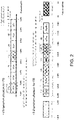
- FIG. 2 illustrates examples of a multi-channel arrangement in a V2X communication system.
- FIG. 2 illustrates examples of multi-channel operation and frequency allocation and usage in North America and in Europe.
- a V2X communication system may allocate seven different frequency channels in the 5.9 GHz band (5.855 to 5.925 GHz). Each frequency channel may have a bandwidth of 10 MHz, although implementations are not limited thereto.
- additional frequency bands may be allocated, e.g., to communicate time-sensitive data, such as an ITS-G63 band at an upper frequency range and an ITS-G5C band at a lower frequency range.
- one channel may be reserved as a control channel (CCH) and six channels may be utilized as service channels (SCH).
- CCH may be allocated to channel number 178 (e.g., in the U.S.) or channel number 180 (e.g., in Europe), and may be utilized as a default channel for common safety communications.
- SCH channels may be available for both safety and non-safety communications.
- messages e.g., service announcement messages
- pairs of channels may be merged to form a single 20 MHz channel, for example, channels 174 and 176 may be merged to form channel 175, and channels 180 and 182 may be merged to form channel 181.
- certain channels e.g., channel 172 may be reserved exclusively for critical safety-of-life communications, and other channels (e.g., channel 184) may be reserved for high-power public safety uses. The remaining channels may be used for non-safety-related applications.
- a set of vehicle safety messages may be provided as WAVE short messages (WSMs) provided by the WAVE Short Message Protocol (WSMP), as defined in the IEEE 1609.3 standard.
- WSMs WAVE short messages
- WSMP WAVE Short Message Protocol
- BSM Basic Safety Message
- vehicle state information e.g., location, speed, acceleration, and heading
- ADAS ADAS
- FIG. 3 illustrates examples of multi-channel operation in a V2X communication system.
- a V2X communication system may implement a series of channel intervals that segment time into alternating Control Channel (CCH) intervals and Service Channel (SCH) intervals. Consecutive intervals may be used to transmit through different channels in an alternating manner (alternating access), or may be used to transmit through a single channel in a continuous manner (extended access).
- CCH Control Channel
- SCH Service Channel
- a communication unit e.g., a DSRC onboard unit in a vehicle
- a communication unit may be configured to, by default, be tuned to a particular channel (e.g., CCH) to send and receive safety messages. If the communication unit then utilizes another channel (e.g., a SCH) to engage in non-safety communications, then the communication unit may alternate between the CCH and SCH channels. Through such alternating channel access, the communication unit may monitor for safety communications during CCH intervals, and communicate non-safety information for other applications during SCH intervals.
- CCH channel
- SCH e.g., SCH
- a guard interval may be inserted between adjacent signal blocks, for example to mitigate effects of delay spread in the wireless communications.
- the guard interval may include a specific sequence to facilitate synchronization or channel estimation at the receiver. For example, in an OFDM system, a cyclic prefix may be inserted into a guard interval of an OFDM symbol. Such guard intervals, however, may be omitted or may be replaced by other structures or techniques having similar or equivalent functionality.
- FIG. 3 illustrates a scenario of alternating between different channels at fixed interval boundaries, which may be referred to as fully synchronous operation
- implementations are not limited thereto.
- Such fully synchronous channel access may be implemented based on an absolute time (e.g., a global positioning satellite, or GPS, time).
- absolute time e.g., a global positioning satellite, or GPS, time
- some implementations may implement channel access in a partially synchronous or asynchronous manner, regardless of interval boundaries, for example according to the contents of the messages being transmitted.
- a V2X communication unit may implement decentralized congestion control (DCC) to adapt its transmission behavior dynamically based on congestion in a channel. For example, a V2X communication unit may monitor a congestion level of a channel and reduce output power, increase inter-packet transmission time, drop packets, and/or reduce transmission rate to mitigate high congestion levels.
- DCC decentralized congestion control
- a problem may arise in that interference caused by non-DCC sources (e.g., interference caused by a device using other protocols, or interference caused by environmental factors) may cause nearby DCC-based communication units to throttle transmission or suffer increased errors for an extended period of time. Such problems may result in delays and errors in transmitting critical safety information for the V2X communication system.
- non-DCC sources e.g., interference caused by a device using other protocols, or interference caused by environmental factors
- a communication unit may switch V2X communications to another channel in a dynamic and adaptive manner based on detected levels of congestion. For example, a communication unit may transmit, to other communication units, a message that includes channel-reassignment information that informs the other communication units to switch to another channel. Such channel-reassignment information may be transmitted on a channel other than the channel originally used for transmitting the V2X communications, thus helping to ensure improved reliability and less delay in switching channels.
- the decision as to whether to switch channels may be made based on additional state information that supplements state information regarding signal interference alone.
- additional state information may include information regarding a number of vehicles in a vicinity of the communication unit (e.g., within a certain number of hops of communication, or within a certain geographic distance), or regarding a number of messages that are detected on the channel, or regarding sensing information that is received from other vehicles (e.g., information sensed by ADAS sensors of other vehicles, including nearby objects), or other types of information that generally relates to a level of congestion (e.g., a number of interference sources) for the channel.
- a level of congestion e.g., a number of interference sources
- AMCO Adaptive Multi-Channel Operation
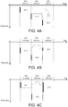
- FIGS. 4A, 4B, and 4C illustrate examples of adaptive multi-channel operation (AMCO), according to some implementations disclosed herein.
- FIGS. 4A to 4C illustrate various examples of switching between channels in an AMCO system.
- a communication unit switches from a first channel to a third channel (or a third range of frequencies) based on channel re- assignment information that is transmitted over a second channel.
- FIG. 4A illustrates an example of switching from a first channel to a third channel that is disjoint from the first channel.
- the communication unit selects the third channel from among multiple candidate channels (e.g., from among the seven 10MHz channels provided in a DSRC system).
- the communication unit may select the third channel based on a level of interference and congestion measured for the third channel.
- the communication unit then shifts the channel load from the first channel to the smaller-load third channel, and informs the channel re-assignment to other vehicles.
- FIG. 4B illustrates an example of segmenting the first channel into multiple channel segments, and switching from the first channel to a third channel (or, in general, a third range of frequencies) that is one of the channel segments within the first channel.
- the first channel may be a 10MHz channel that is segmented into two 5MHz channel segments (e.g., an upper frequency segment, and a lower frequency segment).
- the communication unit may then select one of the channel segments that has acceptable interference and congestion levels, and switch channel assignment from the first channel to the selected channel segment.
- any number of channel segments may be generated that may each have the same or different bandwidths.
- FIG. 4C illustrates an example of merging the first channel with another range of frequencies, and switching from the first channel to a third channel (or a third range of frequencies) that is a result of merged frequencies.
- the communication unit may merge the first channel with an adjacent range of frequencies, resulting in a third channel (or, in general, a third range of frequencies).
- transmission power may be distributed over the larger range of frequencies in the third channel, providing improved resistance to interference that may occur at particular frequencies.
- priority may be given to critical safety communication by assigning such applications to the newly merged adjacent frequencies, while keeping less-critical communications in the original first channel.
- the benefits of ACMO may be further enhanced by prioritizing critical safety applications over lower-priority applications (e.g., non-safety applications, or multi-hop applications).
- channel-reassignment information may be transmitted over a second channel that is different from the first channel and the third channel (or the third range of frequencies).
- transmission of the channel reassignment information may be made more resistant to interference and delays, as compared to transmitting the channel reassignment information through the first channel itself (which may have had high signal interference to begin with).
- dynamic and adaptive channel allocation may be achieved in a fast and reliable manner.
- implementations disclosed herein enable AMCO that adapts flexibly to the influence of congestion or interference.
- FIG. 5 illustrates an example of a scenario of utilizing AMCO, according to some implementations disclosed herein. This example illustrates two different geographic regions, 500 and 502, that each have high levels of signal interference, but that have different sources of that signal interference.
- a large number of vehicles communicate over a common channel (e.g., channel 172).
- a decentralized congestion control (DCC) mechanism the vehicles will cooperate to attempt to reduce the overall level of interference in the channel, thus allowing critical safety information to be transmitted quickly and reliably.
- each of the vehicles may reduce their transmission power (thus reducing interference for other vehicles), or may increase the time between transmitting packets (thus giving other vehicles more opportunities to transmit on lower-interference time intervals), and/or may increase transmission rate (thus reducing the transmission time and allowing other vehicles more time to transmit).
- the vehicles may collectively strive to reduce overall interference in the channel and help prevent delays and errors in critical safety-related communication.
- a non-DCC device such as a drone (or other unmanned aerial vehicle).
- the drone may be continuously transmitting video or other data with high transmission power, disregarding the cooperative congestion control behavior of the DCC protocol. Consequently, a nearby V2X vehicle that implements DCC senses a high level of interference in the channel, and throttles its transmission (e.g., reduces output power and/or increases inter-packet delay) or suffers increased error rate (e.g., increases its transmission rate) according to the DCC protocol.
- the drone does not follow the DCC protocol and therefore continues to transmit at a high transmission power, the DCC vehicle is forced to suffer delays and errors for an extended period of time, potentially disrupting the transmission of safety-critical information.
- DCC-based communication units to recognize whether a high level of interference is caused by high levels of congestion on the road, or whether the interference is caused by non- congestion reasons (e.g., a single source of interference or environmental factors).
- DCC-based communication units are enabled to recognize an abnormal situation of non- congested high-interference, and switch channels and re-assign their V2X communications to a less-congested channel.
- the vehicle in region 502 may utilize various types of information, in addition to signal interference information, to recognize a non-congested and high-interference state.
- additional information may include a number of neighboring vehicles, a number of messages (e.g., V2X messages) transmitted on the channel, road traffic information (e.g., as received from a Traffic Management Center (TMR) or navigation system), and/or sensing information received from nearby vehicles (e.g., ADAS sensor information regarding nearby objects).
- TMR Traffic Management Center
- ADAS sensor information regarding nearby objects e.g., ADAS sensor information regarding nearby objects.
- Such information may generally be referred to as congestion-related information, as they relate to a level of congestion (e.g., a number of potential interference sources), and can be distinguished from interference-related information that simply relates to a level of signal interference (which can be caused by just a single interference source).
- a communication unit may effectively perform adaptive multi-channel operation (AMCO) that adapts to a variety of different situations of interference.
- AMCO adaptive multi-channel operation
- FIG. 6 is a flowchart illustrating an example method 600 of operations performed by a transmitter using AMCO according to some implementations disclosed herein.
- the method 600 may be performed by one or more processors, such as one or more CPUs, GPUs, DSPs, FPGAs, ASICs, TPUs, neuromorphic chips, or vector accelerators that execute instructions encoded on at least one computer storage medium.
- processors such as one or more CPUs, GPUs, DSPs, FPGAs, ASICs, TPUs, neuromorphic chips, or vector accelerators that execute instructions encoded on at least one computer storage medium.
- the method 600 may be used by a communication unit to transmit channel allocation information for V2X (Vehicle-to-Everything) communications in a wireless communication system.
- V2X Vehicle-to-Everything
- the example transmission method 600 includes determining a first channel, among a plurality of channels, that is utilized for V2X communications, the first channel defined by a first range of frequencies (602).
- the plurality of channels may consist of seven channels, each having a bandwidth of 10 MHz, in a 5.9 GHz band of 5.855 GHz to 5.925 GHz, as defined in the DSRC protocol.
- the method 600 further includes determining state information that includes first state information regarding signal interference in the first channel (604).
- the state information is determined by measuring a first ratio of time that the first channel is busy, as perceived by the communication unit; and determining a second ratio of time that the first channel is busy, as perceived by at least one vehicle other than the communication unit.
- measuring the first ratio of time that the first channel is busy, as perceived by the communication unit may include measuring, at a transceiver of the communication unit, signal-to-interference in the first channel; and determining a first duration of time during which the signal-to-interference in the first channel measured at the transceiver of the communication unit exceeds a threshold.
- measuring the second ratio of time that the first channel is busy, as perceived by the at least one vehicle other than the communication unit may include receiving, by the communication unit, information regarding a second duration of time during which signal-to-interference in the first channel measured by the at least one vehicle other than the communication unit exceeds a threshold.
- determining the second ratio of time that the first channel is busy, as perceived by the at least one vehicle other than the communication unit may include receiving, by the communication unit, information regarding the second ratio of time that the first channel is busy, as perceived by a first vehicle that is 1-hop away from the communication unit, or as perceived by a second vehicle that is 2-hops away from the communication unit.
- the state information may further include second state information regarding congestion around the communication unit, the second state information related to a number of sources of interference in the first channel.
- the second state information may include at least one of (i) a number of messages transmitted or received in the first channel by the communication unit or by at least one vehicle other than the communication unit, (ii) a number of neighboring vehicles around the communication unit, or (iii) sensing information detected by the at least one vehicle other than the communication unit.
- the method 600 further includes determining whether the state information satisfies at least one criteria (606).
- determining that the state information satisfies the at least one criteria may include: determining, for the first state information, that the signal interference in the first channel exceeds a threshold interference criteria; and determining, for the second state information, that the congestion around the communication unit does not exceed a threshold congestion criteria.
- the method 600 further includes, based on a determination that the state information satisfies the at least one criteria, determining a second channel, among the plurality of channels, through which to transmit channel-reassignment information, the second channel defined by a second range of frequencies (608).
- the second channel may include a Control Channel (CCH) for DSRC, such as channel number 178.
- CCH Control Channel
- the method 600 further includes determining a third range of frequencies, different from the first and second ranges of frequencies, to which to re-assign the V2X communications of the first channel (610).
- determining the third range of frequencies may include determining a third channel that defines the third range of frequencies to which to re-assign the V2X communications of the first channel, where the third range of frequencies is disjoint from the first range of frequencies of the first channel.
- determining the third range of frequencies may include segmenting the first channel into at least two channel segments, and determining a first channel segment, among the at least two channel segments, that defines the third range of frequencies to which to re-assign the V2X communications of the first channel (the third range of frequencies being a subset of the first range of frequencies of the first channel).
- determining the third range of frequencies may include determining the third range of frequencies as a result of merging the first range of frequencies and a fourth range of frequencies.
- the third channel is determined by monitoring a plurality of candidate channels and their respective signal-to-interference conditions; and determining the third channel having a signal-to-interference that is minimal among the plurality of candidate channels.
- the method 600 further includes transmitting, by the communication unit through the second channel to at least one vehicle, the channel-reassignment information regarding a change in channel assignment for the V2X communications from the first channel to the third range of frequencies (612).
- the channel-reassignment information may be transmitted through the second channel using an IEEE 802.11p-based communication protocol.
- the communication unit may be configured to implement a Wireless Access in Vehicular Environments (WAVE) protocol, and the channel re-assignment information may be configured as a WAVE Service Announcement (WSA) message.
- WAVE Wireless Access in Vehicular Environments
- WSA WAVE Service Announcement
- the channel re-assignment information includes channel bandwidth information and interference information.
- FIG. 7A and 7B are flowcharts illustrating an example method 700 of operations performed by a receiver using AMCO according to some implementations disclosed herein.
- the method 700 may be performed by one or more processors, such as one or more CPUs, GPUs, DSPs, FPGAs, ASICs, TPUs, neuromorphic chips, or vector accelerators that execute instructions encoded on a computer storage medium.
- processors such as one or more CPUs, GPUs, DSPs, FPGAs, ASICs, TPUs, neuromorphic chips, or vector accelerators that execute instructions encoded on a computer storage medium.
- the method 700 may be used by a communication unit to receive channel allocation information for V2X (Vehicle-to-Everything) communications in a wireless communication system.
- V2X Vehicle-to-Everything
- the example reception method 700 includes receiving, by the communication unit through the second channel, channel-reassignment information regarding a change in channel assignment for the V2X communications from a first channel to a third range of frequencies (702).
- the third range of frequencies may be different from a first range of frequencies of the first channel and a second range of frequencies of the second channel.
- the reception method 700 further includes controlling a transceiver of the communication device to change the channel assignment for the V2X communications from the first channel to the third range of frequencies (704).
- the channel-reassignment information described in FIGS. 6 and 7A-7B may be implemented by a particular message (e.g., ChControlMessage, described further below) carrying ITS channel control information.
- a particular message e.g., ChControlMessage, described further below
- the channel reassignment information described in FIGS. 6 and 7A-7B may further include information regarding monitoring channels for signal interference. Such information may be used, for example, to collect interference information that is used to decide whether to switch channels in the AMCO mechanism.
- the receiving communication unit may check a particular field (e.g., a ChControlType field). If the ChControlType field is present, then the receiving communication unit may determine whether to implement one or more monitoring modes. For example, if the ChControlType field has a '0' value, then control may be is released so that no channel monitoring is performed.
- a ChControlType field e.g., a ChControlType field
- the receiving communication unit may check whether an "auto mode” is set, and if "auto mode” is not set, then the receiving communication unit (e.g., an OBU of a vehicle) may guide a driver of the vehicle through instructions (e.g., by navigator or voice) to inform the user of channel environments and turn over channel monitoring control to the driver. Otherwise, if the "auto mode" setting is on, then the receiving communication unit may automatically implement a monitoring mode that is pre-specified, and set a timer using a timer value specified in the ChControlMessage.
- the receiving communication unit may automatically implement a monitoring mode that is pre-specified, and set a timer using a timer value specified in the ChControlMessage.
- the receiving communication unit may mandatorily implement a specified monitoring mode and set a timer to a specified value. Subsequently, the receiving communication unit may wait for the next V2X message.
- V2X communication units may implement various types of power-saving techniques to balance channel monitoring with power consumption.
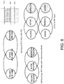
- FIG. 8 illustrates an example of AMCO based on a combination of interference and congestion according to some implementations disclosed herein.
- Congestion information may be used to manage a status of DCC as discussed above.
- the example of FIG. 8 illustrates an example of utilizing congestion information to manage DCC state and interference modes according to some implementations.
- a DCC state management and CST Channel Sensing Threshold
- the signal interference of the channel may be characterized by a channel business ratio (CBR), which may be a ratio of time that the signal interference is above a threshold.
- CBR channel business ratio
- the CBR is classified into three states, "RELAXED” (indicating a low level of interference), "ACTIVE” (indicating a higher level of interference), and "RESTRICTIVE” (indicating the highest level of interference).
- a communication unit may easily classify and determine the interference level of the channel.
- additional congestion information is utilized to augment each state or augment the state space with additional "Interference Mode” or "Interference State” information.
- a binary value of interference mode e.g., "ON” or "OFF" is utilized to indicate an abnormal interference situation (e.g., strong interference caused by a few number of sources). Such a determination may be made, for example, based on whether congestion information (as described previously) is below a threshold (indicating low congestion and therefore likely abnormal interference caused by a few number of non-DCC sources) or above a threshold (indicating high congestion and therefore likely normal interference caused by numerous DCC-based vehicles).
- an interference state is utilized to reflect a more granular level of interference information.
- three interference states may be implemented, indicating whether to "IGNORE” the interference (e.g., due to normal interference caused by numerous DCC-based vehicles), or to provide a "WARNING” (e.g., due to potential medium levels of interference caused by fewer interference sources), or to indicate an "URGENT” interference situation (e.g., due to high levels of interference caused by a few number of non-DCC sources).
- the interference state may be determined based on both signal interference in the channel, as well as congestion information reflecting a number of interference sources (as discussed previously).
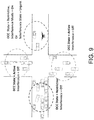
- FIG. 9 illustrates an example of a scenario utilizing a combination of interference and congestion, according to some implementations disclosed herein.
- a communication unit e.g., an OBU of a vehicle
- FIG. 9 illustrates three scenarios in which a vehicle detects a congestion level that exceeds a threshold, and therefore sets an interference mode to be "OFF" to indicate that interference is likely to be caused by a normal situation in which a large number of DCC- based vehicles are concurrently utilizing a channel.
- the DCC state is "ACTIVE” to indicate a medium level of signal interference (CBR value)
- the DCC state is "RESTRICTIVE” to indicate a level of signal interference (CBR value).
- the DCC state determines the remedial action that a DCC-based vehicle will implement to cooperatively reduce interference in the channel (e.g., by reducing power, increasing inter-packet delay, or increasing transmission rate).
- FIG. 9 illustrates one scenario in which a vehicle detects a congestion level that does not exceed a threshold, but detects a high level of signal interference, and therefore sets an interference mode to be "ON” (alternatively, sets an interference state to be "URGENT").
- the AMCO mechanism according to implementations disclosed herein will automatically switch to another channel, to avoid excessive delays and errors in communication caused by non-DCC interference sources.
- FIG. 11 illustrates an example of collecting interference information from other vehicles, according to some implementations disclosed herein.
- an interference monitoring vehicle collects interference information (e.g., CBR information) for AMCO from three other vehicles (vehicle-0, vehicle-1, vehicle-2) according to their respective channels that are being used. As shown in FIG. 11 , the three other vehicles are utilizing one CCH and two SCHs.
- the monitoring vehicle is able to leverage interference information (CBR information) that was received from the three other vehicles to monitor interference levels of the different channels, without necessarily being required to perform separate interference monitoring for each of the different channels in each time slot.
- different vehicles in a V2X communication system may share interference information (e.g., CBR values) collectively monitor interference levels in different channels in an efficient manner.
- FIG. 12 illustrates an example of a system diagram for V2X communications, according to some implementations disclosed herein.
- a V2X system implements DSRC technology, which is composed of a V2X transmitter and a V2X receiver.
- the V2X transmitter 1100 has a DSRC radio unit 1120 for wireless data transmission.
- This DSRC radio unit 1120 may implement the IEEE802.11p standard based on WLAN (Wireless Local Area Networks) and WAVE (Wireless Access in Vehicular Environments).
- the DSRC device processor unit 1130 encodes or decodes the WSM massage.
- the GNSS unit 1110 is configured to utilize a global navigation satellite system (GNSS) to acquire position information and time information.
- GNSS global navigation satellite system
- the application ECU unit 1140 implements one or more processors that provide a specific application service. In order to provide a service, the application ECU unit 1140 generates an action based on sensor information and user input information, and transmits and receives messages through the DSRC / RSU device.
- the sensor unit 1150 is configured to collect vehicle status and surrounding sensor information.
- the human interface unit 1160 provides an interface for a user's input through an input button or touch screen, and a monitor for displaying information, such as a warning message.
- the V2X receiver 1200 is configured to receive a signal sent from the V2X transmitter 1100.
- the V2X receiver 1200 may be mounted on an OBU of an automobile or may be mounted on an RSU, such as a traffic light, to receive a message from the V2X transmitter 1100.
- the receiver structure also includes a DSRC radio unit 1220, a GNSS receiver unit 1210, a DSRC device processor unit 1230, an application ECU unit 1240, a sensor unit 1250, and a human interface unit 1260.
- the DSRC radio unit 1220 and the DSRC device processor unit 1230 may implement a communication technology such as 3GPP, LTE and the like, as defined by North American and European standards, for example.
- FIG. 13 illustrates an example of a protocol stack that implements AMCO according to some implementations disclosed herein.
- the protocol stack implements a number of protocols and corresponding standards.
- the Access layer may correspond to OSI layer 1 (physical layer) and OSI layer 2 (data link layer), and may use PHY technology and MAC technology implementing IEEE802.11p, and may further support IEEE 1609.4 MAC technology to support communication in a vehicular environment.
- the Access layer as defined in IEEE 802.11p, may implement orthogonal frequency division multiplexing (OFDM), and various PHY layer transmission operations such as scrambling, FEC, interleaving, mapping, pilot insertion, IFFT, guard insertion and preamble insertion, PLCP sub-baseband signal processing, wave shaping (e.g., in-phase and quadrature-phase modulation), and digital to analog conversion (DAC).
- OFDM orthogonal frequency division multiplexing
- various PHY layer transmission operations such as scrambling, FEC, interleaving, mapping, pilot insertion, IFFT, guard insertion and preamble insertion, PLCP sub-baseband signal processing, wave shaping (e.g., in-phase and quadrature-phase modulation
- the Networking & Transport layer may implement the IEEE802.2 standard for LLC Block and IEEE 1609.3 technology using the WAVE short message protocol (WSMP), and may correspond to OSI layer 3 (network layer) and OSI layer 4 (transport layer).
- WSMP WAVE short message protocol
- OSI layer 3 network layer
- OSI layer 4 transport layer
- the Networking & Transport layer may implement the IPv6 / TCP protocol to process conventional IP signals.
- the Facilities layer may implement the SAE J2735 standard message set, and may correspond to the OSI layer 5 (session layer) and OSI layer 6 (presentation layer).
- the message set implemented by the Facilities layer may include, for example, a BasicSafetyMessage (BSM) message, a MapData message, a SPAT message, a CommonSafetyRequest message, an EmergencyVehicleAlert message, an IntersectionCollision message, a ProbeVehicleData message, a RoadSideAlert message, and a PersonalSafetyMessage message.
- BSM Basic Safety Message
- the Basic Safety Message is used to transmit (e.g., periodically) various information about a vehicle, such as latitude, longitude, altitude, speed, direction, break, and vehicle size.
- the Application layer may implement the J2945 standard for V2V, V2I, and V2O applications, and may implement, for example, emergency electronic brake lights (EEBL), forward crash warning (FCW), blind spot warning (BSW), lane change warning (LCW), intersection movement assist (IMA) loss warning.
- EEBL emergency electronic brake lights
- FCW forward crash warning
- BW blind spot warning
- LCW lane change warning
- IMA intersection movement assist
- DCC operation may be divided into layers according to the particular functions of each layer.
- the DCC_ACC entity may be included in the Access layer, and may control traffic congestion by adjusting various functions of the Access layer, such as power adjustment.
- the DCC_NET entity may be included in the Networking & Transport layer, and may perform functions such as inserting interference information (e.g., local CBR information) into SHB packet headers for transmission to other vehicles, or receiving global CBR information from neighboring vehicles.
- interference information e.g., local CBR information
- the DCC_FAC entity may be included in the Facilities layer and may control traffic congestion by adjusting various functions of the Facilities layer, such as message generation rate.
- the DCC_CROSS entity may be included in the Management entity, and may perform overall DCC operations such as providing DCC parameters or CBR values to entities such as DCC_Access, DCC_NET, and DCC_FAC.
- TPC TPC
- the output power is altered to adjust the current channel load.
- the ITS-S can reduce its output power and thereby, is a reduction in interference range achieved. This results in that ITS-Ss further away will experience a reduced CBR.
- TRC TRC regulates the time between two consecutive packets from an ITS-S.
- the TRC increases the time between two packets for the ITS-S, Toff time.
- TDC TDC is a mechanism that can be used by wireless systems offering several transfer rate options. During high utilization periods and depending on application, a higher transfer rate can be used to decreased the Ton time.
- DCC parameter evaluation includes global CBR information obtained from neighboring vehicles (e.g., from a neighbor table located in the Networking & Transport layer) and local CBR information (e.g., provided from the DCC_ACC entity of the Access layer) to generate interference information used in the AMCO.
- the generated interference information may be transmitted to different DCC entities in the Access layer, Networking and Transport layer, and Facilities layer, to be used for performing DCC functions belonging to the corresponding protocol layer.
- the Access Layer may be configured to monitor various state indicators, such as: (i) the CBR in percentage values; (ii) SNR or Receiver Signal Strength Indicator (RSSI) statistics; (iii) Transmitter power reduction per message if a message cannot be transmitted; and (iv) Frames transmission indication regarding whether a message has been successfully transmitted or dropped.
- state indicators such as: (i) the CBR in percentage values; (ii) SNR or Receiver Signal Strength Indicator (RSSI) statistics; (iii) Transmitter power reduction per message if a message cannot be transmitted; and (iv) Frames transmission indication regarding whether a message has been successfully transmitted or dropped.
- the Access Layer provides the above information to the Management Entity via the MI-SAP message protocol.
- the multi-channel operation (MCO) structure includes a channel coordination part in which channel access is defined, a channel routing part that defines overall data and frame management operations between the PHY-MACs, an Enhanced Dedicated Channel Access (EDCA) portion, and a data buffers (queues) portion for storing frames received from upper layers.
- EDCA Enhanced Dedicated Channel Access
- a data buffers (queues) portion for storing frames received from upper layers.
- Channel coordination channel access may be defined, for example, as CCH (control channel) and SCH (service channel).
- Data buffers stores frames received from upper layers according to the defined AC (Access Category).Each data buffer may have its own AC.
- Channel routing transmits the data received from upper layers to the data buffer (queue), and performs transmission operations such as channel coordination, channel numbering for frame transmission, transmission power, and data rate control.
- EDCA guaranteeing quality of service (QoS) in the IEEE 802.11e MAC layer. This may be divided into four access categories (AC) according to the type of traffic. Different priorities may be assigned to each category, and differentiated parameters may be allocated for each AC. This may implement a competition-based medium access approach that allows more transmission opportunities for higher-priority traffic.
- a V2X transceiver may expand an existing WSMP message set, or develop a new message that informs a channel switching operation in the AMCO mechanism.
- the MCO and DCC control of the Management layer may be modified to implement enhanced congestion monitoring.
- the Access layer may be modified to implement AMCO.
- a new message referred to as a CCM Channel Control Message
- an existing announcement message e.g., WSM
- channel bandwidth information and the corresponding CBR information may be transmitted together.
- the message may be composed of ID information, location information, time information, guide information, information about whether a channel is divided into multiple channels, and information regarding channel bandwidth and CBR.
- the ID information may include a msgId field indicating the information of the corresponding message, and the corresponding value may be in the form of DSRCmsgID data frame in the J2735 standard.
- a stationPosition field and a stationType field may indicate location information.
- StationPosition which indicates the location of the measuring station, may display the location of the measuring station using Position3D of the J2735 standard.
- the stationType field may indicate the type of the station, e.g., a value of '1' indicating the actual measurement station, and a value of '2' indicating an RSU that transmits predicted data.
- the dataGenerationTime and msgGenerationTime, and updateTime fields indicate various time information for message. All of these fields may use the DTime field of the J2735 standard.
- the dataGenerationTime field represents the measurement time of CBR information in the system
- the msgGenerationTime field represents the message generation time
- the updateTime field represents a time when the power for external interference is measured / updated.
- the ChControlMessage (CCM) format may be implemented according to the example below.
- a monitoring mode may be specified in the CCM, using the ChControlType in the ChControlMessage.
- ChControl which is a data frame defining ChControlType, is defined in Table 2 in this specification.
- ChControl is written using ASN.1, and SEQUENCE defines mode control for FullMonitoring mode, SavingMonitoring mode, and TriggerMonitoring mode.
- FullMonitoring corresponds to monitoring the channel load (e.g., continuously) for all available radio bandwidths.
- SavingMonitoring refers to monitoring the channel automatically at fixed times according to a specified policy.
- ConditionalMonitoring defers to scanning all power levels of available channels and finding the most suitable channel when it is determined that the interference in a channel exceeds a threshold.
- CurrentCLData and historyCLData refer to current and history channel load data, respectively.
- Current channel load data is transmitted and includes channel frequency range, bandwidth, and channel load information.
- a data frame of ChControl may be utilized, as shown in Table 2, below.
- the above three monitoring modes may be supported, and each mode may be associated with a value of Mode and Lifetime.
- AutoStopLifetime indicates the validity period of the mode control using DTime.
- AutoStop and Recirculation also have a Mode and Lifetime.
- ChControlMode is a data frame indicating the monitoring mode and may be set to ENUMERATED. If the value is '0', then it releases the monitoring mode. If it is '1', then the monitoring mode is set to 'On' with OnRecommend. However, if Auto mode is set, then the monitoring mode may be set automatically. In case of the value '2', OnMandatory is a mode which forces the monitoring mode to be 'On'.
- FIG. 13 is a diagram illustrating an example of a computing system that may be used to implement one or more components of a V2X communication system utilizing AMCO.
- the example system of FIG. 13 shows a computing device 1300 and a mobile computing device 1350 that can be used to implement the techniques described herein.
- a communication unit e.g., an OBU, RSU, or VRU in FIG. 1
- V2X transmitter 1100 and V2X receiver 1200 in FIG. 12 could be an example of the device 1300 described here, such as V2X transmitter 1100 and V2X receiver 1200 in FIG. 12 .
- the computing device 1300 is intended to represent various forms of digital computers, such as laptops, desktops, workstations, personal digital assistants, servers, blade servers, mainframes, and other appropriate computers.
- the mobile computing device 1350 is intended to represent various forms of mobile devices, such as personal digital assistants, cellular telephones, smart-phones, and other similar computing devices.
- the components shown here, their connections and relationships, and their functions, are meant to be examples only, and are not meant to be limiting.
- the computing device 1300 includes a processor 1302, a memory 1304, a storage device 1306, a high-speed interface 1308 connecting to the memory 1304 and multiple high- speed expansion ports 1310, and a low-speed interface 1312 connecting to a low-speed expansion port 1314 and the storage device 1306.
- Each of the processor 1302, the memory 1304, the storage device 1306, the high-speed interface 1308, the high-speed expansion ports 1310, and the low-speed interface 1312 are interconnected using various busses, and may be mounted on a common motherboard or in other manners as appropriate.
- the processor 1302 can process instructions for execution within the computing device 1300, including instructions stored in the memory 1304 or on the storage device 1306 to display graphical information for a GUI on an external input/output device, such as a display 1316 coupled to the high-speed interface 1308.
- multiple processors and/or multiple buses may be used, as appropriate, along with multiple memories and types of memory.
- multiple computing devices may be connected, with each device providing portions of the operations (e.g., as a server bank, a group of blade servers, or a multi-processor system).
- the processor 1302 is a single-threaded processor.
- the processor 1302 is a multi-threaded processor.
- the processor 1302 is a quantum computer.
- the memory 1304 stores information within the computing device 1300.
- the memory 1304 is a volatile memory unit or units.
- the memory 1304 is a non-volatile memory unit or units.
- the memory 1304 may also be another form of computer-readable medium, such as a magnetic or optical disk.
- the storage device 1306 is capable of providing mass storage for the computing device 1300.
- the storage device 1306 may be or may include a computer- readable medium, such as a floppy disk device, a hard disk device, an optical disk device, or a tape device, a flash memory or other similar solid-state memory device, or an array of devices, including devices in a storage area network or other configurations.
- Instructions can be stored in an information carrier.
- the instructions when executed by one or more processing devices (for example, processor 1302), perform one or more methods, such as those described above.
- the instructions can also be stored by one or more storage devices such as computer- or machine- readable mediums (for example, the memory 1304, the storage device 1306, or memory on the processor 1302).
- the high-speed interface 1308 manages bandwidth-intensive operations for the computing device 1300, while the low-speed interface 1312 manages lower bandwidth-intensive operations. Such allocation of functions is an example only.
- the high- speed interface 1308 is coupled to the memory 1304, the display 1316 (e.g., through a graphics processor or accelerator), and to the high-speed expansion ports 1310, which may accept various expansion cards (not shown).
- the low-speed interface 1312 is coupled to the storage device 1306 and the low-speed expansion port 1314.
- the low-speed expansion port 1314 which may include various communication ports (e.g., USB, Bluetooth, Ethernet, wireless Ethernet) may be coupled to one or more input/output devices, such as a keyboard, a pointing device, a scanner, or a networking device such as a switch or router, e.g., through a network adapter.
- input/output devices such as a keyboard, a pointing device, a scanner, or a networking device such as a switch or router, e.g., through a network adapter.
- the computing device 1300 may be implemented in a number of different forms, as shown in the figure. For example, it may be implemented as a standard server 1320, or multiple times in a group of such servers. In addition, it may be implemented in a personal computer such as a laptop computer 1322. It may also be implemented as part of a rack server system 1324. Alternatively, components from the computing device 1300 may be combined with other components in a mobile device (not shown), such as a mobile computing device 1350. Each of such devices may include one or more of the computing device 1300 and the mobile computing device 1350, and an entire system may be made up of multiple computing devices communicating with each other.
- the mobile computing device 1350 includes a processor 1352, a memory 1364, an input/output device such as a display 1354, a communication interface 1366, and a transceiver 1368, among other components.
- the mobile computing device 1350 may also be provided with a storage device, such as a micro-drive or other device, to provide additional storage.
- a storage device such as a micro-drive or other device, to provide additional storage.
- Each of the processor 1352, the memory 1364, the display 1354, the communication interface 1366, and the transceiver 1368, are interconnected using various buses, and several of the components may be mounted on a common motherboard or in other manners as appropriate.
- the processor 1352 can execute instructions within the mobile computing device 1350, including instructions stored in the memory 1364.
- the processor 1352 may be implemented as a chipset of chips that include separate and multiple analog and digital processors.
- the processor 1352 may provide, for example, for coordination of the other components of the mobile computing device 1350, such as control of user interfaces, applications run by the mobile computing device 1350, and wireless communication by the mobile computing device 1350.
- the processor 1352 may communicate with a user through a control interface 1358 and a display interface 1356 coupled to the display 1354.
- the display 1354 may be, for example, a TFT (Thin-Film-Transistor Liquid Crystal Display) display or an OLED (Organic Light Emitting Diode) display, or other appropriate display technology.
- the display interface 1356 may comprise appropriate circuitry for driving the display 1354 to present graphical and other information to a user.
- the control interface 1358 may receive commands from a user and convert them for submission to the processor 1352.
- an external interface 1362 may provide communication with the processor 1352, so as to enable near area communication of the mobile computing device 1350 with other devices.
- the external interface 1362 may provide, for example, for wired communication in some implementations, or for wireless communication in other implementations, and multiple interfaces may also be used.
- the memory 1364 stores information within the mobile computing device 1350.
- the memory 1364 can be implemented as one or more of a computer-readable medium or media, a volatile memory unit or units, or a non-volatile memory unit or units.
- An expansion memory 1374 may also be provided and connected to the mobile computing device 1350 through an expansion interface 1372, which may include, for example, a SIMM (Single In Line Memory Module) card interface.
- SIMM Single In Line Memory Module
- the expansion memory 1374 may provide extra storage space for the mobile computing device 1350, or may also store applications or other information for the mobile computing device 1350.
- the expansion memory 1374 may include instructions to carry out or supplement the processes described above, and may include secure information also.
- the expansion memory 1374 may be provide as a security module for the mobile computing device 1350, and may be programmed with instructions that permit secure use of the mobile computing device 1350.
- secure applications may be provided via the SIMM cards, along with additional information, such as placing identifying information on the SIMM card in a non-hackable manner.
- the memory may include, for example, flash memory and/or NVRAM memory (non- volatile random access memory), as discussed below.
- instructions are stored in an information carrier such that the instructions, when executed by one or more processing devices (for example, processor 1352), perform one or more methods, such as those described above.
- the instructions can also be stored by one or more storage devices, such as one or more computer- or machine-readable mediums (for example, the memory 1364, the expansion memory 1374, or memory on the processor 1352).
- the instructions can be received in a propagated signal, for example, over the transceiver 1368 or the external interface 1362.
- the mobile computing device 1350 may communicate wirelessly through the communication interface 1366, which may include digital signal processing circuitry.
- the communication interface 1366 may provide for communications under various modes or protocols, such as GSM voice calls (Global System for Mobile communications), SMS (Short Message Service), EMS (Enhanced Messaging Service), or MMS messaging (Multimedia Messaging Service), CDMA (code division multiple access), TDMA (time division multiple access), PDC (Personal Digital Cellular), WCDMA (Wideband Code Division Multiple Access), CDMA2000, or GPRS (General Packet Radio Service), among others.
- GSM voice calls Global System for Mobile communications
- SMS Short Message Service
- EMS Enhanced Messaging Service
- MMS messaging Multimedia Messaging Service
- CDMA code division multiple access
- TDMA time division multiple access
- PDC Personal Digital Cellular
- WCDMA Wideband Code Division Multiple Access
- CDMA2000 Code Division Multiple Access
- GPRS General Packet Radio Service
- GPS Global Positioning System
- short-range communication may occur, such as using a Bluetooth, Wi-Fi, or other such transceiver (not shown).
- a GPS (Global Positioning System) receiver module 1370 may provide additional navigation- and location-related wireless data to the mobile computing device 1350, which may be used as appropriate by applications running on the mobile computing device 1350.
- the mobile computing device 1350 may also communicate audibly using an audio codec 1360, which may receive spoken information from a user and convert it to usable digital information.
- the audio codec 1360 may likewise generate audible sound for a user, such as through a speaker, e.g., in a handset of the mobile computing device 1350.
- Such sound may include sound from voice telephone calls, may include recorded sound (e.g., voice messages, music files, etc.) and may also include sound generated by applications operating on the mobile computing device 1350.
- the mobile computing device 1350 may be implemented in a number of different forms, as shown in the figure. For example, it may be implemented as a cellular telephone 1380. It may also be implemented as part of a smart-phone 1382, personal digital assistant, or other similar mobile device.
- system may encompass all apparatus, devices, and machines for processing data, including by way of example a programmable processor, a computer, or multiple processors or computers.
- a processing system can include, in addition to hardware, code that creates an execution environment for the computer program in question, e.g., code that constitutes processor firmware, a protocol stack, a database management system, an operating system, or a combination of one or more of them.
- a computer program (also known as a program, software, software application, script, executable logic, or code) can be written in any form of programming language, including compiled or interpreted languages, or declarative or procedural languages, and it can be deployed in any form, including as a standalone program or as a module, component, subroutine, or other unit suitable for use in a computing environment.
- a computer program does not necessarily correspond to a file in a file system.
- a program can be stored in a portion of a file that holds other programs or data (e.g., one or more scripts stored in a markup language document), in a single file dedicated to the program in question, or in multiple coordinated files (e.g., files that store one or more modules, sub programs, or portions of code).
- a computer program can be deployed to be executed on one computer or on multiple computers that are located at one site or distributed across multiple sites and interconnected by a communication network.
- Computer readable media suitable for storing computer program instructions and data include all forms of non-volatile or volatile memory, media and memory devices, including by way of example semiconductor memory devices, e.g., EPROM, EEPROM, and flash memory devices; magnetic disks, e.g., internal hard disks or removable disks or magnetic tapes; magneto optical disks; and CD-ROM and DVD-ROM disks.
- semiconductor memory devices e.g., EPROM, EEPROM, and flash memory devices
- magnetic disks e.g., internal hard disks or removable disks or magnetic tapes
- magneto optical disks and CD-ROM and DVD-ROM disks.
- the processor and the memory can be supplemented by, or incorporated in, special purpose logic circuitry.
- a server is a general-purpose computer, and sometimes it is a custom-tailored special purpose electronic device, and sometimes it is a combination of these things.
- Implementations can include a back end component, e.g., a data server, or a middleware component, e.g., an application server, or a front end component, e.g., a client computer having a graphical user interface or a Web browser through which a user can interact with an implementation of the subject matter described is this specification, or any combination of one or more such back end, middleware, or front end components.
- the components of the system can be interconnected by any form or medium of digital data communication, e.g., a communication network. Examples of communication networks include a local area network (“LAN”) and a wide area network (“WAN”), e.g., the Internet.
- LAN local area network
- WAN wide area network
- the features described can be implemented in digital electronic circuitry, or in computer hardware, firmware, software, or in combinations of them.
- the apparatus can be implemented in a computer program product tangibly embodied in an information carrier, e.g., in a machine-readable storage device, for execution by a programmable processor; and method steps can be performed by a programmable processor executing a program of instructions to perform functions of the described implementations by operating on input data and generating output.
- the described features can be implemented advantageously in one or more computer programs that are executable on a programmable system including at least one programmable processor coupled to receive data and instructions from, and to transmit data and instructions to, a data storage system, at least one input device, and at least one output device.
- a computer program is a set of instructions that can be used, directly or indirectly, in a computer to perform a certain activity or bring about a certain result.
- a computer program can be written in any form of programming language, including compiled or interpreted languages, and it can be deployed in any form, including as a stand-alone program or as a module, component, subroutine, or other unit suitable for use in a computing environment.
Landscapes
- Engineering & Computer Science (AREA)
- Computer Networks & Wireless Communication (AREA)
- Signal Processing (AREA)
- Physics & Mathematics (AREA)
- Electromagnetism (AREA)
- Quality & Reliability (AREA)
- Mobile Radio Communication Systems (AREA)
Claims (13)
- Verfahren zum Senden von Kanalzuordnungsinformation für Fahrzeug-zu-Allem-, V2X, Kommunikationen in einem Drahtloskommunikationssystem durch eine Kommunikationseinheit, wobei das Verfahren umfasst:Bestimmen eines ersten Kanals aus einer Mehrzahl von Kanälen, der zu V2X-Kommunikationen verwendet wird, wobei der erste Kanal durch einen ersten Frequenzbereich definiert ist (S602);Bestimmen einer Zustandsinformation, die eine erste Zustandsinformation umfasst, bezüglich einer Signalinterferenz im ersten Kanal (S604);Bestimmen, ob die Zustandsinformation mindestens ein Kriterium erfüllt;basierend auf einer Bestimmung, dass die Zustandsinformation das mindestens eine Kriterium erfüllt (S606):Bestimmen eines zweiten Kanals aus der Mehrzahl von Kanälen, über den eine Kanalneuzuweisungsinformation übertragbar ist, wobei der zweite Kanal durch einen zweiten Frequenzbereich definiert ist (S608);Bestimmen eines dritten Frequenzbereichs, dem die V2X-Kommunikationen des ersten Kanals neu zugewiesen werden (S610);Segmentieren des ersten Kanals in mindestens zwei Kanalsegmente;Bestimmen eines ersten Kanalsegments aus den mindestens zwei Kanalsegmenten, das den dritten Frequenzbereich definiert, dem die V2X-Kommunikationen des ersten Kanals neu zugewiesen werden; undSenden der Kanalneuzuweisungsinformation bezüglich einer Änderung der Kanalzuweisung für die V2X-Kommunikationen vom ersten Kanal zum dritten Frequenzbereich durch die Kommunikationseinheit über den zweiten Kanal an mindestens ein Fahrzeug (S612),wobei der dritte Frequenzbereich eine Teilmenge des ersten Frequenzbereichs des ersten Kanals ist.
- Verfahren nach Anspruch 1, wobei das Bestimmen des dritten Frequenzbereichs, der sich von dem ersten und dem zweiten Frequenzbereich unterscheidet, dem die V2X-Kommunikationen des ersten Kanals neu zugewiesen werden, umfasst:Bestimmen eines dritten Kanals aus der Mehrzahl von Kanälen, der den dritten Frequenzbereich definiert, dem die V2X-Kommunikationen des ersten Kanals neu zugewiesen werden,wobei der dritte Frequenzbereich vom ersten Frequenzbereich des ersten Kanals disjunkt ist.
- Verfahren nach Anspruch 1, wobei das Bestimmen des dritten Frequenzbereichs, der sich von dem ersten und dem zweiten Frequenzbereich unterscheidet, dem die V2X-Kommunikationen des ersten Kanals neu zugewiesen werden, umfasst:
Bestimmen des dritten Frequenzbereichs als ein Ergebnis einer Zusammenführung des ersten Frequenzbereichs und eines vierten Frequenzbereichs. - Verfahren nach einem vorhergehenden Anspruch, wobei das Bestimmen des dritten Frequenzbereichs, der sich vom ersten und zweiten Frequenzbereich unterscheidet, dem die V2X-Kommunikationen des ersten Kanals neu zugewiesen werden, umfasst:Überwachen einer Mehrzahl von Kandidatenkanälen und ihrer jeweiligen Signal-zu-Interferenz-Bedingungen unter der Mehrzahl von Kanälen; undBestimmen eines dritten Kanals mit einem Signal-zu-Interferenz-Verhältnis, das unter der Mehrzahl von Kandidatenkanälen minimal ist, basierend auf dem Überwachen der Mehrzahl von Kandidatenkanälen und ihrer jeweiligen Signal-zu-Interferenz-Bedingungen.
- Verfahren nach einem vorhergehenden Anspruch, wobei das Bestimmen der Zustandsinformation, die die erste Zustandsinformation umfasst, bezüglich einer Signalinterferenz in dem ersten Kanal Folgendes umfasst:Messen eines ersten Zeitverhältnisses, in dem der erste Kanal belegt ist, wie von der Kommunikationseinheit wahrgenommen; undBestimmen eines zweiten Zeitverhältnisses, in dem der erste Kanal belegt ist, wie es von mindestens einem anderen Fahrzeug als der Kommunikationseinheit wahrgenommen wird.
- Verfahren nach Anspruch 5, wobei das Messen des ersten Zeitverhältnisses, in dem der erste Kanal belegt ist, wie es von der Kommunikationseinheit wahrgenommen wird, Folgendes umfasst:Messen eines Signal-zu-Interferenz-Verhältnisses im ersten Kanal an einem Transceiver der Kommunikationseinheit; undBestimmen einer ersten Zeitdauer, während der das am Transceiver der Kommunikationseinheit gemessene Signal-zu-Interferenz-Verhältnis in dem ersten Kanal einen ersten Schwellenwert überschreitet.
- Verfahren nach Anspruch 5 oder 6, wobei das Bestimmen des zweiten Zeitverhältnisses, in dem der erste Kanal belegt ist, wie es von mindestens einem anderen Fahrzeug als der Kommunikationseinheit wahrgenommen wird, Folgendes umfasst:
Empfangen einer Information bezüglich einer zweiten Zeitdauer, während der das von mindestens einem anderen Fahrzeug als der Kommunikationseinheit gemessene Signal-zu-Interferenz-Verhältnis im ersten Kanal einen zweiten Schwellenwert überschreitet, durch die Kommunikationseinheit. - Verfahren nach einem der Ansprüche 5 bis 7, wobei das Bestimmen des zweiten Zeitverhältnisses, in dem der erste Kanal belegt ist, wie es von mindestens einem anderen Fahrzeug als der Kommunikationseinheit wahrgenommen wird, Folgendes umfasst:
Empfangen einer Information bezüglich des zweiten Zeitverhältnisses, in dem der erste Kanal belegt ist, wie es von einem ersten Fahrzeug wahrgenommen wird, das einen Sprung von der Kommunikationseinheit entfernt ist, oder wie es von einem zweiten Fahrzeug wahrgenommen wird, das zwei Sprünge von der Kommunikationseinheit entfernt ist, durch die Kommunikationseinheit. - Verfahren nach einem vorhergehenden Anspruch, wobei die Zustandsinformation ferner eine zweite Zustandsinformation bezüglich einer Überlastung rund um die Kommunikationseinheit umfasst, wobei die zweite Zustandsinformation auf eine Anzahl von Störquellen in dem ersten Kanal bezogen ist.
- Verfahren nach Anspruch 9, wobei die zweite Zustandsinformation bezüglich einer Überlastung rund um die Kommunikationseinheit mindestens eines der Folgenden umfasst:(i) eine Anzahl von Nachrichten, die auf dem ersten Kanal von der Kommunikationseinheit oder von mindestens einem anderen Fahrzeug als der Kommunikationseinheit gesendet oder empfangen wurden;(ii) eine Anzahl benachbarter Fahrzeuge rund um die Kommunikationseinheit und(iii) Erfassen einer Information, die von mindestens einem anderen Fahrzeug als der Kommunikationseinheit erfasst wurde.
- Verfahren nach Anspruch 9 oder 10, wobei das Bestimmen, dass die Zustandsinformation das mindestens ein Kriterium erfüllt, Folgendes umfasst:Bestimmen für die erste Zustandsinformation, dass die Signalinterferenz in dem ersten Kanal ein Schwelleninterferenzkriterium überschreitet; undBestimmen für die zweite Zustandsinformation, dass die Überlastung rund um die Kommunikationseinheit ein Schwellenüberlastungskriterium nicht überschreitet.
- Verfahren nach einem vorhergehenden Anspruch, wobei der zweite Kanal einen Steuerkanal, CCH, umfasst, der den V2X-Kommunikationen zugewiesen wurde.
- Kommunikationseinheit, die eingerichtet ist, um eine Kanalzuordnungsinformation für Fahrzeug-zu-Allem-, V2X, Kommunikationen in einem Drahtloskommunikationssystem zu senden, wobei die Kommunikationseinheit Folgendes umfasst:einen Transceiver;mindestens einen Prozessor; undmindestens einen Computerspeicher, der betriebsfähig mit dem mindestens einen Prozessor verbunden werden kann und auf dem Anweisungen gespeichert sind, die,wenn sie ausgeführt werden, den mindestens einen Prozessor veranlassen,Betriebsvorgänge auszuführen, die Folgendes umfassen:Bestimmen eines ersten Kanals aus einer Mehrzahl von Kanälen, der zu V2X-Kommunikationen verwendet wird, wobei der erste Kanal durch einen ersten Frequenzbereich definiert ist;Bestimmen einer Zustandsinformation, die eine erste Zustandsinformation umfasst, bezüglich einer Signalinterferenz im ersten Kanal;Bestimmen, ob die Zustandsinformation mindestens ein Kriterium erfüllt; undbasierend auf einer Bestimmung, dass die Zustandsinformation das mindestens eine Kriterium erfüllt:Bestimmen eines zweiten Kanals aus der Mehrzahl von Kanälen, über den eine Kanalneuzuweisungsinformation übertragbar ist, wobei der zweite Kanal durch einen zweiten Frequenzbereich definiert ist;Bestimmen eines dritten Frequenzbereichs, dem die V2X-Kommunikationen des ersten Kanals neu zugewiesen werden;Segmentieren des ersten Kanals in mindestens zwei Kanalsegmente;Bestimmen eines ersten Kanalsegments aus den mindestens zwei Kanalsegmenten,das den dritten Frequenzbereich definiert, dem die V2X-Kommunikationen des ersten Kanals neu zugewiesen werden; undSenden der Kanalneuzuweisungsinformation bezüglich einer Änderung einer Kanalzuweisung für die V2X-Kommunikationen vom ersten Kanal zum dritten Frequenzbereich durch die Kommunikationseinheit über den zweiten Kanal an mindestens ein Fahrzeug,wobei der dritte Frequenzbereich eine Teilmenge des ersten Frequenzbereichs des ersten Kanals ist.
Applications Claiming Priority (2)
| Application Number | Priority Date | Filing Date | Title |
|---|---|---|---|
| US201862679026P | 2018-06-01 | 2018-06-01 | |
| US16/363,248 US10917891B2 (en) | 2018-06-01 | 2019-03-25 | Adaptive multi-channel V2X communication |
Publications (2)
| Publication Number | Publication Date |
|---|---|
| EP3576440A1 EP3576440A1 (de) | 2019-12-04 |
| EP3576440B1 true EP3576440B1 (de) | 2021-03-03 |
Family
ID=66630088
Family Applications (1)
| Application Number | Title | Priority Date | Filing Date |
|---|---|---|---|
| EP19174961.3A Active EP3576440B1 (de) | 2018-06-01 | 2019-05-16 | Adaptive mehrkanalige v2x-kommunikation |
Country Status (3)
| Country | Link |
|---|---|
| US (1) | US10917891B2 (de) |
| EP (1) | EP3576440B1 (de) |
| CN (1) | CN110557210B (de) |
Families Citing this family (33)
| Publication number | Priority date | Publication date | Assignee | Title |
|---|---|---|---|---|
| EP3244677B1 (de) * | 2016-05-13 | 2020-04-29 | Panasonic Intellectual Property Corporation of America | Verbesserter mechanismus zur qos-implementierung in der fahrzeugkommunikation |
| JP6950703B2 (ja) * | 2016-10-20 | 2021-10-13 | ソニーグループ株式会社 | 通信制御装置、通信制御方法及びコンピュータプログラム |
| CN109428609B (zh) * | 2017-08-24 | 2022-04-19 | 西安中兴新软件有限责任公司 | 一种干扰处理方法和装置 |
| WO2019198837A1 (ko) * | 2018-04-09 | 2019-10-17 | 엘지전자(주) | V2x 통신 장치 및 그의 오동작 obe 검출 방법 |
| US10869190B2 (en) * | 2018-07-13 | 2020-12-15 | Micron Technology, Inc. | Secure vehicular services communication |
| CN109121098B (zh) * | 2018-08-24 | 2021-05-25 | 京东方科技集团股份有限公司 | 一种分配信道的方法及系统 |
| US11407423B2 (en) * | 2019-12-26 | 2022-08-09 | Intel Corporation | Ego actions in response to misbehaving vehicle identification |
| KR20220125244A (ko) * | 2020-01-10 | 2022-09-14 | 퀄컴 인코포레이티드 | 로드 사이드 유닛 메시지 스케줄링 및 혼잡 제어 |
| WO2021143406A1 (zh) * | 2020-01-14 | 2021-07-22 | 华为技术有限公司 | 一种消息发送方法、消息接收方法、装置和设备 |
| US11080993B1 (en) * | 2020-03-26 | 2021-08-03 | Qualcomm Incorporated | Vehicle to everything communication management according to a vulnerable roadside user device configuration |
| US20210250911A1 (en) * | 2020-04-28 | 2021-08-12 | Intel Corporation | Enhanced vehicle communications |
| CN113630128A (zh) * | 2020-05-06 | 2021-11-09 | 展讯通信(上海)有限公司 | 一种频率处理方法、装置、终端设备及存储介质 |
| AU2020451276B2 (en) * | 2020-06-01 | 2023-11-23 | Telefonaktiebolaget Lm Ericsson (Publ) | Application function node, access and mobility management function node, system and methods in a communications network |
| CN114095520B (zh) * | 2020-07-21 | 2024-01-19 | 中信科智联科技有限公司 | 一种定位数据的确定方法、车联网设备及装置 |
| JP7371593B2 (ja) * | 2020-09-14 | 2023-10-31 | 株式会社デンソー | 無線通信制御装置、無線通信装置、及び無線通信制御方法 |
| CN112654880B (zh) * | 2020-09-18 | 2022-07-22 | 华为技术有限公司 | 资源确定方法、装置、电子设备、存储介质以及车辆 |
| CN112423263B (zh) * | 2020-11-05 | 2023-12-08 | 中国联合网络通信集团有限公司 | 网络拥塞控制方法和装置 |
| US11647366B2 (en) * | 2020-11-16 | 2023-05-09 | Qualcomm Incorporated | Adaptive RSSI adjustment |
| US11412363B2 (en) * | 2020-11-16 | 2022-08-09 | Qualcomm Incorporated | Context-adaptive RSSI-based misbehavior detection |
| CN114615741A (zh) * | 2020-12-03 | 2022-06-10 | 深圳市法马新智能设备有限公司 | 无线交通信号机及其信号处理方法 |
| CN115119165B (zh) * | 2021-03-19 | 2025-09-19 | 大唐移动通信设备有限公司 | 控制用于v2x通信的功率的方法、设备及可读存储介质 |
| WO2022226452A1 (en) * | 2021-04-23 | 2022-10-27 | Qualcomm Incorporated | Combining channel busy ratios received from multiple user equipments |
| US11910415B2 (en) * | 2021-04-23 | 2024-02-20 | Qualcomm Incorporated | Combining channel busy ratios received from multiple user equipments |
| EP4109997A1 (de) * | 2021-06-22 | 2022-12-28 | INTEL Corporation | Verfahren und vorrichtungen zum schutz der v2x-kommunikation vor nahbandstörungen |
| US12255696B2 (en) * | 2021-09-24 | 2025-03-18 | Qualcomm Incorporated | Detection of radio frequency signal transfer anomalies |
| US12279210B2 (en) | 2021-11-18 | 2025-04-15 | Qualcomm Incorporated | Roadside unit message transmission management |
| IT202200002624A1 (it) * | 2022-02-14 | 2023-08-14 | Anas Spa | Sistema di telecomunicazioni stradale |
| CN115150325B (zh) * | 2022-06-29 | 2024-04-09 | 东北大学 | 一种应用于b5g车载网的可靠路由方法 |
| US12349172B2 (en) | 2022-09-08 | 2025-07-01 | Ford Global Technologies, Llc | Adaptive out-of-band interference avoidance |
| CN116208521B (zh) * | 2022-12-09 | 2024-12-17 | 潍柴动力股份有限公司 | 传感器报文通道识别方法、装置、电子设备和存储介质 |
| CN119183084A (zh) * | 2023-06-21 | 2024-12-24 | 华为技术有限公司 | 一种通信方法、电子设备及介质 |
| CN119210618B (zh) * | 2024-11-26 | 2025-02-07 | 北京历正科技有限责任公司 | 多协议无线信号处理方法、系统、电子设备及存储介质 |
| CN121151948B (zh) * | 2025-11-17 | 2026-02-03 | 钛马信息网络技术有限公司 | 一种面向车联网环境的通信负载检测系统及方法 |
Family Cites Families (12)
| Publication number | Priority date | Publication date | Assignee | Title |
|---|---|---|---|---|
| US20120093091A1 (en) * | 2010-10-17 | 2012-04-19 | Industrial Technology Research Institute | Method and system for extended service channel access on demand in an alternating wireless channel access environment |
| WO2015019234A1 (en) * | 2013-08-05 | 2015-02-12 | Universidade De Aveiro | Method and apparatus for multi-network communication in vehicular networks |
| KR101506598B1 (ko) * | 2013-11-29 | 2015-03-27 | 현대모비스 주식회사 | 차량간 통신을 위한 통신 장치 |
| US10015720B2 (en) * | 2014-03-14 | 2018-07-03 | GoTenna, Inc. | System and method for digital communication between computing devices |
| KR101603436B1 (ko) * | 2014-10-16 | 2016-03-21 | 경북대학교 산학협력단 | 차량의 긴급 메시지 브로드캐스팅 방법 |
| WO2016198320A1 (en) | 2015-06-08 | 2016-12-15 | Nec Europe Ltd. | Method for multi-channel operation in a vehicular network and vehicular network |
| WO2017048100A1 (ko) * | 2015-09-17 | 2017-03-23 | 엘지전자 주식회사 | 무선 통신 시스템에서 v2x 단말의 메시지 송수신 방법 및 장치 |
| WO2017066912A1 (en) * | 2015-10-19 | 2017-04-27 | Huawei Technologies Co., Ltd. | Method for communication, server, roadside unit and node |
| EP3412103B1 (de) * | 2016-02-04 | 2025-01-15 | Apple Inc. | Sensorbasierte kollisionsverhinderung für v2v-kommunikation |
| CN107396293B (zh) * | 2017-08-03 | 2020-12-18 | 重庆邮电大学 | 基于d2d通信的v2x资源分配方法及系统 |
| CN107889077B (zh) * | 2017-11-01 | 2020-06-09 | 浙江如新智能科技有限公司 | 一种基于车联网技术的快速数据传输方法 |
| US11039458B2 (en) * | 2017-11-21 | 2021-06-15 | Qualcomm Incorporated | Methods and apparatuses for transmission scheduling on multiple frequencies |
-
2019
- 2019-03-25 US US16/363,248 patent/US10917891B2/en active Active
- 2019-05-16 EP EP19174961.3A patent/EP3576440B1/de active Active
- 2019-05-31 CN CN201910469419.4A patent/CN110557210B/zh active Active
Non-Patent Citations (1)
| Title |
|---|
| None * |
Also Published As
| Publication number | Publication date |
|---|---|
| US10917891B2 (en) | 2021-02-09 |
| US20190373609A1 (en) | 2019-12-05 |
| CN110557210B (zh) | 2022-10-25 |
| EP3576440A1 (de) | 2019-12-04 |
| CN110557210A (zh) | 2019-12-10 |
Similar Documents
| Publication | Publication Date | Title |
|---|---|---|
| EP3576440B1 (de) | Adaptive mehrkanalige v2x-kommunikation | |
| Le et al. | Comprehensive survey of radio resource allocation schemes for 5G V2X communications | |
| US10856335B2 (en) | Base station, terminal device, and communication method | |
| US11304036B2 (en) | V2X communication apparatus and method for transmitting and receiving V2X message therefor | |
| US10779189B2 (en) | Congestion control for vehicular-to-anything services | |
| US11978342B2 (en) | Method for transmitting safety message in wireless communication system supporting sidelink and apparatus therefortherefor | |
| US20210029674A1 (en) | Communication device | |
| Sjöberg | Medium access control for vehicular ad hoc networks | |
| Dayal et al. | Adaptive semi-persistent scheduling for enhanced on-road safety in decentralized V2X networks | |
| US10348444B2 (en) | Speed dependent transmission format for vehicular transmission | |
| US10044589B2 (en) | Adaptive rate control for cellular-based vehicular networks | |
| KR20180111780A (ko) | 통신 디바이스, 기지국 및 통신 방법 | |
| US11978344B2 (en) | Method for transmitting, by UE, message in wireless communication system supporting sidelink, and apparatus therefor | |
| US20220264455A1 (en) | Method for ue transmitting sidelink signal in wireless communication system supporting sidelink, and device therefor | |
| CN115843457B (zh) | 无线通信的信道占用 | |
| EP4280637B1 (de) | Verfahren zur übertragung einer nachricht durch ein endgerät in einem drahtloskommunikationssystem und vorrichtung dafür | |
| US20240292454A1 (en) | Method for performing sidelink communication by terminal in wireless communication system and device therefor | |
| US12035203B2 (en) | Method for terminal to transmit first message in wireless communication system supporting sidelink, and device for same | |
| KR20240144120A (ko) | 사이드링크 포지셔닝에서의 부분 감지 | |
| WO2018027989A1 (zh) | 一种通信方法和装置 | |
| Charpentier et al. | Latency-aware C-ITS application for improving the road safety with CAM messages on the Smart Highway testbed | |
| US12096319B2 (en) | Method by which first device transmits message in wireless communication system supporting sidelink, and device therefor | |
| Chakroun et al. | An effective location-based alert messages dissemination scheme for software defined vehicular networks | |
| US20240416939A1 (en) | Advanced driver assistance system sensitivity adjustments | |
| US20240237114A1 (en) | Method for transmitting message including terminal information in wireless communication system, and apparatus therefor |
Legal Events
| Date | Code | Title | Description |
|---|---|---|---|
| PUAI | Public reference made under article 153(3) epc to a published international application that has entered the european phase |
Free format text: ORIGINAL CODE: 0009012 |
|
| STAA | Information on the status of an ep patent application or granted ep patent |
Free format text: STATUS: THE APPLICATION HAS BEEN PUBLISHED |
|
| AK | Designated contracting states |
Kind code of ref document: A1 Designated state(s): AL AT BE BG CH CY CZ DE DK EE ES FI FR GB GR HR HU IE IS IT LI LT LU LV MC MK MT NL NO PL PT RO RS SE SI SK SM TR |
|
| AX | Request for extension of the european patent |
Extension state: BA ME |
|
| STAA | Information on the status of an ep patent application or granted ep patent |
Free format text: STATUS: REQUEST FOR EXAMINATION WAS MADE |
|
| 17P | Request for examination filed |
Effective date: 20200602 |
|
| RBV | Designated contracting states (corrected) |
Designated state(s): AL AT BE BG CH CY CZ DE DK EE ES FI FR GB GR HR HU IE IS IT LI LT LU LV MC MK MT NL NO PL PT RO RS SE SI SK SM TR |
|
| GRAP | Despatch of communication of intention to grant a patent |
Free format text: ORIGINAL CODE: EPIDOSNIGR1 |
|
| STAA | Information on the status of an ep patent application or granted ep patent |
Free format text: STATUS: GRANT OF PATENT IS INTENDED |
|
| RIC1 | Information provided on ipc code assigned before grant |
Ipc: H04W 36/06 20090101ALI20200910BHEP Ipc: H04W 72/08 20090101ALI20200910BHEP Ipc: H04W 72/04 20090101ALI20200910BHEP Ipc: H04W 28/02 20090101ALN20200910BHEP Ipc: H04W 72/12 20090101ALI20200910BHEP Ipc: H04W 4/40 20180101AFI20200910BHEP Ipc: H04W 74/08 20090101ALI20200910BHEP Ipc: H04W 4/90 20180101ALN20200910BHEP |
|
| INTG | Intention to grant announced |
Effective date: 20201001 |
|
| RIN1 | Information on inventor provided before grant (corrected) |
Inventor name: KIM, SOYOUNG |
|
| GRAS | Grant fee paid |
Free format text: ORIGINAL CODE: EPIDOSNIGR3 |
|
| GRAA | (expected) grant |
Free format text: ORIGINAL CODE: 0009210 |
|
| STAA | Information on the status of an ep patent application or granted ep patent |
Free format text: STATUS: THE PATENT HAS BEEN GRANTED |
|
| AK | Designated contracting states |
Kind code of ref document: B1 Designated state(s): AL AT BE BG CH CY CZ DE DK EE ES FI FR GB GR HR HU IE IS IT LI LT LU LV MC MK MT NL NO PL PT RO RS SE SI SK SM TR |
|
| REG | Reference to a national code |
Ref country code: GB Ref legal event code: FG4D |
|
| REG | Reference to a national code |
Ref country code: CH Ref legal event code: EP Ref country code: AT Ref legal event code: REF Ref document number: 1368584 Country of ref document: AT Kind code of ref document: T Effective date: 20210315 |
|
| REG | Reference to a national code |
Ref country code: DE Ref legal event code: R096 Ref document number: 602019002883 Country of ref document: DE |
|
| REG | Reference to a national code |
Ref country code: IE Ref legal event code: FG4D |
|
| REG | Reference to a national code |
Ref country code: LT Ref legal event code: MG9D |
|
| PG25 | Lapsed in a contracting state [announced via postgrant information from national office to epo] |
Ref country code: NO Free format text: LAPSE BECAUSE OF FAILURE TO SUBMIT A TRANSLATION OF THE DESCRIPTION OR TO PAY THE FEE WITHIN THE PRESCRIBED TIME-LIMIT Effective date: 20210603 Ref country code: LT Free format text: LAPSE BECAUSE OF FAILURE TO SUBMIT A TRANSLATION OF THE DESCRIPTION OR TO PAY THE FEE WITHIN THE PRESCRIBED TIME-LIMIT Effective date: 20210303 Ref country code: BG Free format text: LAPSE BECAUSE OF FAILURE TO SUBMIT A TRANSLATION OF THE DESCRIPTION OR TO PAY THE FEE WITHIN THE PRESCRIBED TIME-LIMIT Effective date: 20210603 Ref country code: HR Free format text: LAPSE BECAUSE OF FAILURE TO SUBMIT A TRANSLATION OF THE DESCRIPTION OR TO PAY THE FEE WITHIN THE PRESCRIBED TIME-LIMIT Effective date: 20210303 Ref country code: FI Free format text: LAPSE BECAUSE OF FAILURE TO SUBMIT A TRANSLATION OF THE DESCRIPTION OR TO PAY THE FEE WITHIN THE PRESCRIBED TIME-LIMIT Effective date: 20210303 Ref country code: GR Free format text: LAPSE BECAUSE OF FAILURE TO SUBMIT A TRANSLATION OF THE DESCRIPTION OR TO PAY THE FEE WITHIN THE PRESCRIBED TIME-LIMIT Effective date: 20210604 |
|
| REG | Reference to a national code |
Ref country code: NL Ref legal event code: MP Effective date: 20210303 |
|
| REG | Reference to a national code |
Ref country code: AT Ref legal event code: MK05 Ref document number: 1368584 Country of ref document: AT Kind code of ref document: T Effective date: 20210303 |
|
| PG25 | Lapsed in a contracting state [announced via postgrant information from national office to epo] |
Ref country code: LV Free format text: LAPSE BECAUSE OF FAILURE TO SUBMIT A TRANSLATION OF THE DESCRIPTION OR TO PAY THE FEE WITHIN THE PRESCRIBED TIME-LIMIT Effective date: 20210303 Ref country code: PL Free format text: LAPSE BECAUSE OF FAILURE TO SUBMIT A TRANSLATION OF THE DESCRIPTION OR TO PAY THE FEE WITHIN THE PRESCRIBED TIME-LIMIT Effective date: 20210303 Ref country code: RS Free format text: LAPSE BECAUSE OF FAILURE TO SUBMIT A TRANSLATION OF THE DESCRIPTION OR TO PAY THE FEE WITHIN THE PRESCRIBED TIME-LIMIT Effective date: 20210303 Ref country code: SE Free format text: LAPSE BECAUSE OF FAILURE TO SUBMIT A TRANSLATION OF THE DESCRIPTION OR TO PAY THE FEE WITHIN THE PRESCRIBED TIME-LIMIT Effective date: 20210303 |
|
| PG25 | Lapsed in a contracting state [announced via postgrant information from national office to epo] |
Ref country code: NL Free format text: LAPSE BECAUSE OF FAILURE TO SUBMIT A TRANSLATION OF THE DESCRIPTION OR TO PAY THE FEE WITHIN THE PRESCRIBED TIME-LIMIT Effective date: 20210303 |
|
| PG25 | Lapsed in a contracting state [announced via postgrant information from national office to epo] |
Ref country code: EE Free format text: LAPSE BECAUSE OF FAILURE TO SUBMIT A TRANSLATION OF THE DESCRIPTION OR TO PAY THE FEE WITHIN THE PRESCRIBED TIME-LIMIT Effective date: 20210303 Ref country code: CZ Free format text: LAPSE BECAUSE OF FAILURE TO SUBMIT A TRANSLATION OF THE DESCRIPTION OR TO PAY THE FEE WITHIN THE PRESCRIBED TIME-LIMIT Effective date: 20210303 Ref country code: SM Free format text: LAPSE BECAUSE OF FAILURE TO SUBMIT A TRANSLATION OF THE DESCRIPTION OR TO PAY THE FEE WITHIN THE PRESCRIBED TIME-LIMIT Effective date: 20210303 Ref country code: AT Free format text: LAPSE BECAUSE OF FAILURE TO SUBMIT A TRANSLATION OF THE DESCRIPTION OR TO PAY THE FEE WITHIN THE PRESCRIBED TIME-LIMIT Effective date: 20210303 |
|
| PG25 | Lapsed in a contracting state [announced via postgrant information from national office to epo] |
Ref country code: IS Free format text: LAPSE BECAUSE OF FAILURE TO SUBMIT A TRANSLATION OF THE DESCRIPTION OR TO PAY THE FEE WITHIN THE PRESCRIBED TIME-LIMIT Effective date: 20210703 Ref country code: RO Free format text: LAPSE BECAUSE OF FAILURE TO SUBMIT A TRANSLATION OF THE DESCRIPTION OR TO PAY THE FEE WITHIN THE PRESCRIBED TIME-LIMIT Effective date: 20210303 Ref country code: PT Free format text: LAPSE BECAUSE OF FAILURE TO SUBMIT A TRANSLATION OF THE DESCRIPTION OR TO PAY THE FEE WITHIN THE PRESCRIBED TIME-LIMIT Effective date: 20210705 Ref country code: SK Free format text: LAPSE BECAUSE OF FAILURE TO SUBMIT A TRANSLATION OF THE DESCRIPTION OR TO PAY THE FEE WITHIN THE PRESCRIBED TIME-LIMIT Effective date: 20210303 |
|
| REG | Reference to a national code |
Ref country code: DE Ref legal event code: R097 Ref document number: 602019002883 Country of ref document: DE |
|
| PLBE | No opposition filed within time limit |
Free format text: ORIGINAL CODE: 0009261 |
|
| STAA | Information on the status of an ep patent application or granted ep patent |
Free format text: STATUS: NO OPPOSITION FILED WITHIN TIME LIMIT |
|
| PG25 | Lapsed in a contracting state [announced via postgrant information from national office to epo] |
Ref country code: LU Free format text: LAPSE BECAUSE OF NON-PAYMENT OF DUE FEES Effective date: 20210516 Ref country code: DK Free format text: LAPSE BECAUSE OF FAILURE TO SUBMIT A TRANSLATION OF THE DESCRIPTION OR TO PAY THE FEE WITHIN THE PRESCRIBED TIME-LIMIT Effective date: 20210303 Ref country code: AL Free format text: LAPSE BECAUSE OF FAILURE TO SUBMIT A TRANSLATION OF THE DESCRIPTION OR TO PAY THE FEE WITHIN THE PRESCRIBED TIME-LIMIT Effective date: 20210303 Ref country code: MC Free format text: LAPSE BECAUSE OF FAILURE TO SUBMIT A TRANSLATION OF THE DESCRIPTION OR TO PAY THE FEE WITHIN THE PRESCRIBED TIME-LIMIT Effective date: 20210303 Ref country code: ES Free format text: LAPSE BECAUSE OF FAILURE TO SUBMIT A TRANSLATION OF THE DESCRIPTION OR TO PAY THE FEE WITHIN THE PRESCRIBED TIME-LIMIT Effective date: 20210303 |
|
| 26N | No opposition filed |
Effective date: 20211206 |
|
| REG | Reference to a national code |
Ref country code: BE Ref legal event code: MM Effective date: 20210531 |
|
| PG25 | Lapsed in a contracting state [announced via postgrant information from national office to epo] |
Ref country code: SI Free format text: LAPSE BECAUSE OF FAILURE TO SUBMIT A TRANSLATION OF THE DESCRIPTION OR TO PAY THE FEE WITHIN THE PRESCRIBED TIME-LIMIT Effective date: 20210303 |
|
| PG25 | Lapsed in a contracting state [announced via postgrant information from national office to epo] |
Ref country code: IT Free format text: LAPSE BECAUSE OF FAILURE TO SUBMIT A TRANSLATION OF THE DESCRIPTION OR TO PAY THE FEE WITHIN THE PRESCRIBED TIME-LIMIT Effective date: 20210303 Ref country code: IE Free format text: LAPSE BECAUSE OF NON-PAYMENT OF DUE FEES Effective date: 20210516 |
|
| PG25 | Lapsed in a contracting state [announced via postgrant information from national office to epo] |
Ref country code: IS Free format text: LAPSE BECAUSE OF FAILURE TO SUBMIT A TRANSLATION OF THE DESCRIPTION OR TO PAY THE FEE WITHIN THE PRESCRIBED TIME-LIMIT Effective date: 20210703 |
|
| PG25 | Lapsed in a contracting state [announced via postgrant information from national office to epo] |
Ref country code: BE Free format text: LAPSE BECAUSE OF NON-PAYMENT OF DUE FEES Effective date: 20210531 |
|
| REG | Reference to a national code |
Ref country code: CH Ref legal event code: PL |
|
| PG25 | Lapsed in a contracting state [announced via postgrant information from national office to epo] |
Ref country code: LI Free format text: LAPSE BECAUSE OF NON-PAYMENT OF DUE FEES Effective date: 20220531 Ref country code: CH Free format text: LAPSE BECAUSE OF NON-PAYMENT OF DUE FEES Effective date: 20220531 |
|
| PG25 | Lapsed in a contracting state [announced via postgrant information from national office to epo] |
Ref country code: CY Free format text: LAPSE BECAUSE OF FAILURE TO SUBMIT A TRANSLATION OF THE DESCRIPTION OR TO PAY THE FEE WITHIN THE PRESCRIBED TIME-LIMIT Effective date: 20210303 |
|
| PG25 | Lapsed in a contracting state [announced via postgrant information from national office to epo] |
Ref country code: HU Free format text: LAPSE BECAUSE OF FAILURE TO SUBMIT A TRANSLATION OF THE DESCRIPTION OR TO PAY THE FEE WITHIN THE PRESCRIBED TIME-LIMIT; INVALID AB INITIO Effective date: 20190516 |
|
| PG25 | Lapsed in a contracting state [announced via postgrant information from national office to epo] |
Ref country code: MK Free format text: LAPSE BECAUSE OF FAILURE TO SUBMIT A TRANSLATION OF THE DESCRIPTION OR TO PAY THE FEE WITHIN THE PRESCRIBED TIME-LIMIT Effective date: 20210303 |
|
| PG25 | Lapsed in a contracting state [announced via postgrant information from national office to epo] |
Ref country code: TR Free format text: LAPSE BECAUSE OF FAILURE TO SUBMIT A TRANSLATION OF THE DESCRIPTION OR TO PAY THE FEE WITHIN THE PRESCRIBED TIME-LIMIT Effective date: 20210303 |
|
| PG25 | Lapsed in a contracting state [announced via postgrant information from national office to epo] |
Ref country code: MT Free format text: LAPSE BECAUSE OF FAILURE TO SUBMIT A TRANSLATION OF THE DESCRIPTION OR TO PAY THE FEE WITHIN THE PRESCRIBED TIME-LIMIT Effective date: 20210303 |
|
| PGFP | Annual fee paid to national office [announced via postgrant information from national office to epo] |
Ref country code: DE Payment date: 20250407 Year of fee payment: 7 |
|
| PGFP | Annual fee paid to national office [announced via postgrant information from national office to epo] |
Ref country code: FR Payment date: 20250408 Year of fee payment: 7 |
|
| PGFP | Annual fee paid to national office [announced via postgrant information from national office to epo] |
Ref country code: GB Payment date: 20260309 Year of fee payment: 8 |