EP3576384B1 - Terminal mobile - Google Patents
Terminal mobile Download PDFInfo
- Publication number
- EP3576384B1 EP3576384B1 EP17893914.6A EP17893914A EP3576384B1 EP 3576384 B1 EP3576384 B1 EP 3576384B1 EP 17893914 A EP17893914 A EP 17893914A EP 3576384 B1 EP3576384 B1 EP 3576384B1
- Authority
- EP
- European Patent Office
- Prior art keywords
- mobile terminal
- antenna
- touch
- sensor
- unit
- Prior art date
- Legal status (The legal status is an assumption and is not a legal conclusion. Google has not performed a legal analysis and makes no representation as to the accuracy of the status listed.)
- Active
Links
- 239000000463 material Substances 0.000 claims description 2
- 238000004891 communication Methods 0.000 description 50
- 230000006870 function Effects 0.000 description 28
- 238000000034 method Methods 0.000 description 17
- 238000005516 engineering process Methods 0.000 description 10
- 230000003287 optical effect Effects 0.000 description 10
- 230000005855 radiation Effects 0.000 description 10
- 230000000694 effects Effects 0.000 description 9
- 238000010295 mobile communication Methods 0.000 description 8
- 230000005540 biological transmission Effects 0.000 description 7
- 239000004020 conductor Substances 0.000 description 7
- 238000010586 diagram Methods 0.000 description 7
- 230000005684 electric field Effects 0.000 description 7
- 210000003811 finger Anatomy 0.000 description 6
- 230000008569 process Effects 0.000 description 6
- 239000002184 metal Substances 0.000 description 5
- 229910052751 metal Inorganic materials 0.000 description 5
- 239000003990 capacitor Substances 0.000 description 4
- 230000005672 electromagnetic field Effects 0.000 description 4
- 230000007774 longterm Effects 0.000 description 4
- 238000012545 processing Methods 0.000 description 4
- 230000004044 response Effects 0.000 description 4
- 238000003860 storage Methods 0.000 description 4
- 238000012546 transfer Methods 0.000 description 4
- 238000005286 illumination Methods 0.000 description 3
- 239000007769 metal material Substances 0.000 description 3
- 238000004078 waterproofing Methods 0.000 description 3
- 238000010168 coupling process Methods 0.000 description 2
- 238000001514 detection method Methods 0.000 description 2
- 238000009826 distribution Methods 0.000 description 2
- 239000010408 film Substances 0.000 description 2
- 230000006698 induction Effects 0.000 description 2
- 239000004973 liquid crystal related substance Substances 0.000 description 2
- 230000033001 locomotion Effects 0.000 description 2
- 238000004519 manufacturing process Methods 0.000 description 2
- 239000011159 matrix material Substances 0.000 description 2
- 238000000926 separation method Methods 0.000 description 2
- 239000004984 smart glass Substances 0.000 description 2
- 229910001220 stainless steel Inorganic materials 0.000 description 2
- 239000010935 stainless steel Substances 0.000 description 2
- 229920003002 synthetic resin Polymers 0.000 description 2
- 239000000057 synthetic resin Substances 0.000 description 2
- 239000010936 titanium Substances 0.000 description 2
- 230000000007 visual effect Effects 0.000 description 2
- XUIMIQQOPSSXEZ-UHFFFAOYSA-N Silicon Chemical compound [Si] XUIMIQQOPSSXEZ-UHFFFAOYSA-N 0.000 description 1
- RTAQQCXQSZGOHL-UHFFFAOYSA-N Titanium Chemical compound [Ti] RTAQQCXQSZGOHL-UHFFFAOYSA-N 0.000 description 1
- 230000001133 acceleration Effects 0.000 description 1
- 230000003213 activating effect Effects 0.000 description 1
- 230000004075 alteration Effects 0.000 description 1
- 229910052782 aluminium Inorganic materials 0.000 description 1
- XAGFODPZIPBFFR-UHFFFAOYSA-N aluminium Chemical compound [Al] XAGFODPZIPBFFR-UHFFFAOYSA-N 0.000 description 1
- 238000013459 approach Methods 0.000 description 1
- 230000015556 catabolic process Effects 0.000 description 1
- 230000001413 cellular effect Effects 0.000 description 1
- 230000008859 change Effects 0.000 description 1
- 239000003086 colorant Substances 0.000 description 1
- 230000003247 decreasing effect Effects 0.000 description 1
- 238000006731 degradation reaction Methods 0.000 description 1
- 230000000593 degrading effect Effects 0.000 description 1
- 230000001419 dependent effect Effects 0.000 description 1
- 230000009977 dual effect Effects 0.000 description 1
- -1 for example Substances 0.000 description 1
- 210000005224 forefinger Anatomy 0.000 description 1
- 239000011521 glass Substances 0.000 description 1
- 230000036541 health Effects 0.000 description 1
- 230000001976 improved effect Effects 0.000 description 1
- 230000001939 inductive effect Effects 0.000 description 1
- 238000002347 injection Methods 0.000 description 1
- 239000007924 injection Substances 0.000 description 1
- 238000001746 injection moulding Methods 0.000 description 1
- 238000009434 installation Methods 0.000 description 1
- 238000002955 isolation Methods 0.000 description 1
- 238000012986 modification Methods 0.000 description 1
- 230000004048 modification Effects 0.000 description 1
- 210000003205 muscle Anatomy 0.000 description 1
- 239000012811 non-conductive material Substances 0.000 description 1
- 230000010355 oscillation Effects 0.000 description 1
- 238000003909 pattern recognition Methods 0.000 description 1
- 230000002093 peripheral effect Effects 0.000 description 1
- 230000035807 sensation Effects 0.000 description 1
- 229910052710 silicon Inorganic materials 0.000 description 1
- 239000010703 silicon Substances 0.000 description 1
- 239000010454 slate Substances 0.000 description 1
- 239000007787 solid Substances 0.000 description 1
- 239000000243 solution Substances 0.000 description 1
- 230000005236 sound signal Effects 0.000 description 1
- 239000007921 spray Substances 0.000 description 1
- 230000003068 static effect Effects 0.000 description 1
- 230000000638 stimulation Effects 0.000 description 1
- 239000000126 substance Substances 0.000 description 1
- 239000000758 substrate Substances 0.000 description 1
- 230000008093 supporting effect Effects 0.000 description 1
- 239000010409 thin film Substances 0.000 description 1
- 229910052719 titanium Inorganic materials 0.000 description 1
- XLYOFNOQVPJJNP-UHFFFAOYSA-N water Substances O XLYOFNOQVPJJNP-UHFFFAOYSA-N 0.000 description 1
Images


Classifications
-
- H—ELECTRICITY
- H04—ELECTRIC COMMUNICATION TECHNIQUE
- H04M—TELEPHONIC COMMUNICATION
- H04M1/00—Substation equipment, e.g. for use by subscribers
- H04M1/02—Constructional features of telephone sets
- H04M1/0202—Portable telephone sets, e.g. cordless phones, mobile phones or bar type handsets
- H04M1/0249—Details of the mechanical connection between the housing parts or relating to the method of assembly
-
- H—ELECTRICITY
- H01—ELECTRIC ELEMENTS
- H01Q—ANTENNAS, i.e. RADIO AERIALS
- H01Q1/00—Details of, or arrangements associated with, antennas
- H01Q1/12—Supports; Mounting means
- H01Q1/22—Supports; Mounting means by structural association with other equipment or articles
- H01Q1/24—Supports; Mounting means by structural association with other equipment or articles with receiving set
- H01Q1/241—Supports; Mounting means by structural association with other equipment or articles with receiving set used in mobile communications, e.g. GSM
- H01Q1/242—Supports; Mounting means by structural association with other equipment or articles with receiving set used in mobile communications, e.g. GSM specially adapted for hand-held use
- H01Q1/243—Supports; Mounting means by structural association with other equipment or articles with receiving set used in mobile communications, e.g. GSM specially adapted for hand-held use with built-in antennas
-
- H—ELECTRICITY
- H04—ELECTRIC COMMUNICATION TECHNIQUE
- H04M—TELEPHONIC COMMUNICATION
- H04M1/00—Substation equipment, e.g. for use by subscribers
- H04M1/02—Constructional features of telephone sets
- H04M1/0202—Portable telephone sets, e.g. cordless phones, mobile phones or bar type handsets
- H04M1/026—Details of the structure or mounting of specific components
-
- H—ELECTRICITY
- H01—ELECTRIC ELEMENTS
- H01Q—ANTENNAS, i.e. RADIO AERIALS
- H01Q1/00—Details of, or arrangements associated with, antennas
- H01Q1/44—Details of, or arrangements associated with, antennas using equipment having another main function to serve additionally as an antenna, e.g. means for giving an antenna an aesthetic aspect
-
- H—ELECTRICITY
- H01—ELECTRIC ELEMENTS
- H01Q—ANTENNAS, i.e. RADIO AERIALS
- H01Q1/00—Details of, or arrangements associated with, antennas
- H01Q1/52—Means for reducing coupling between antennas; Means for reducing coupling between an antenna and another structure
- H01Q1/521—Means for reducing coupling between antennas; Means for reducing coupling between an antenna and another structure reducing the coupling between adjacent antennas
-
- H—ELECTRICITY
- H01—ELECTRIC ELEMENTS
- H01Q—ANTENNAS, i.e. RADIO AERIALS
- H01Q13/00—Waveguide horns or mouths; Slot antennas; Leaky-waveguide antennas; Equivalent structures causing radiation along the transmission path of a guided wave
- H01Q13/10—Resonant slot antennas
-
- H—ELECTRICITY
- H04—ELECTRIC COMMUNICATION TECHNIQUE
- H04M—TELEPHONIC COMMUNICATION
- H04M1/00—Substation equipment, e.g. for use by subscribers
- H04M1/02—Constructional features of telephone sets
- H04M1/0202—Portable telephone sets, e.g. cordless phones, mobile phones or bar type handsets
- H04M1/026—Details of the structure or mounting of specific components
- H04M1/0277—Details of the structure or mounting of specific components for a printed circuit board assembly
-
- H—ELECTRICITY
- H01—ELECTRIC ELEMENTS
- H01Q—ANTENNAS, i.e. RADIO AERIALS
- H01Q1/00—Details of, or arrangements associated with, antennas
- H01Q1/48—Earthing means; Earth screens; Counterpoises
Definitions
- the present disclosure relates to a mobile terminal having a structure capable of ensuring antenna performance even when a bezel size is reduced.
- Terminals may be generally classified as mobile/portable terminals or stationary terminals according to their mobility. Mobile terminals may also be classified as handheld terminals or vehicle mounted terminals according to whether or not a user can directly carry the terminal.
- Mobile terminals have become increasingly more functional. Examples of such functions include data and voice communications, capturing images and video via a camera, recording audio, playing music files via a speaker system, and displaying images and video on a display. Some mobile terminals include additional functionality which supports game playing, while other terminals are configured as multimedia players. More recently, mobile terminals have been configured to receive broadcast and multicast signals which permit viewing of content such as videos and television programs.
- the mobile terminal can support more complicated functions such as capturing images or video, reproducing music or video files, playing games, receiving broadcast signals, and the like.
- the mobile terminal may be embodied in the form of a multimedia player or device.
- antennas having different frequency characteristics are configured.
- a plurality of antennas operating in one frequency band may be configured to transmit or receive data simultaneously or sequentially.
- Document EP 3 086 403 A1 relates to a mobile terminal including an antenna for transmitting and receiving a wireless communication signal.
- Document EP 3 098 902 A1 relates to an electronic device including an antenna device.
- the present disclosure aims to provide a mobile terminal having antennas in which interferences between the plurality of antennas may be minimized.
- the mobile terminal may have the increased number of Wi-Fi antennas to increase the data transmission speed.
- the antenna performance can be ensured such that the size of the bezel of the top of the display unit can be reduced.
- a singular representation may include a plural representation unless it represents a definitely different meaning from the context.
- Mobile terminals presented herein may be implemented using a variety of different types of terminals. Examples of such terminals include cellular phones, smart phones, user equipment, laptop computers, digital broadcast terminals, personal digital assistants (PDAs), portable multimedia players (PMPs), navigators, portable computers (PCs), slate PCs, tablet PCs, ultra books, wearable devices (for example, smart watches, smart glasses, head mounted displays (HMDs)), and the like.
- PDAs personal digital assistants
- PMPs portable multimedia players
- PCs portable computers
- slate PCs slate PCs
- tablet PCs tablet PCs
- ultra books ultra books
- wearable devices for example, smart watches, smart glasses, head mounted displays (HMDs)
- FIG. 1A is a block diagram of a mobile terminal in accordance with the present disclosure
- FIGS. 1B and 1C are conceptual views of one example of the mobile terminal, viewed from different directions.
- the mobile terminal 100 is shown having components such as a wireless communication unit 110, an input unit 120, a sensing unit 140, an output unit 150, an interface unit 160, a memory 170, a controller 180, and a power supply unit 190.
- a wireless communication unit 110 configured with several commonly implemented components. It is understood that implementing all of the illustrated components is not a requirement, and that greater or fewer components may alternatively be implemented.
- the wireless communication unit 110 typically includes one or more modules which permit communications such as wireless communications between the mobile terminal 100 and a wireless communication system, communications between the mobile terminal 100 and another mobile terminal, communications between the mobile terminal 100 and an external server. Further, the wireless communication unit 110 typically includes one or more modules which connect the mobile terminal 100 to one or more networks.
- the wireless communication unit 110 includes one or more of a broadcast receiving module 111, a mobile communication module 112, a wireless Internet module 113, a short-range communication module 114, and a location information module 115.
- the input unit 120 includes a camera 121 for obtaining images or video, a microphone 122, which is one type of audio input device for inputting an audio signal, and a user input unit 123 (for example, a touch key, a push key, a mechanical key, a soft key, and the like) for allowing a user to input information.
- Data for example, audio, video, image, and the like
- controller 180 may analyze and process data (for example, audio, video, image, and the like) according to device parameters, user commands, and combinations thereof.
- the sensing unit 140 is typically implemented using one or more sensors configured to sense internal information of the mobile terminal, the surrounding environment of the mobile terminal, user information, and the like.
- the sensing unit 140 may alternatively or additionally include other types of sensors or devices, such as a proximity sensor 141 and an illumination sensor 142, a touch sensor, an acceleration sensor, a magnetic sensor, a G-sensor, a gyroscope sensor, a motion sensor, an RGB sensor, an infrared (IR) sensor, a finger scan sensor, a ultrasonic sensor, an optical sensor (for example, camera 121), a microphone 122, a battery gauge, an environment sensor (for example, a barometer, a hygrometer, a thermometer, a radiation detection sensor, a thermal sensor, and a gas sensor, among others), and a chemical sensor (for example, an electronic nose, a health care sensor, a biometric sensor, and the like), to name a few.
- the mobile terminal 100 may be configured to utilize information obtained from sensing unit
- the output unit 150 is typically configured to output various types of information, such as audio, video, tactile output, and the like.
- the output unit 150 is shown having a display unit 151, an audio output module 152, a haptic module 153, and an optical output module 154.
- the display unit 151 may have an inter-layered structure or an integrated structure with a touch sensor in order to facilitate a touch screen.
- the touch screen may provide an output interface between the mobile terminal 100 and a user, as well as function as the user input unit 123 which provides an input interface between the mobile terminal 100 and the user.
- the interface unit 160 serves as an interface with various types of external devices that can be coupled to the mobile terminal 100.
- the interface unit 160 may include any of wired or wireless ports, external power supply ports, wired or wireless data ports, memory card ports, ports for connecting a device having an identification module, audio input/output (I/O) ports, video I/O ports, earphone ports, and the like.
- the mobile terminal 100 may perform assorted control functions associated with a connected external device, in response to the external device being connected to the interface unit 160.
- the memory 170 is typically implemented to store data to support various functions or features of the mobile terminal 100.
- the memory 170 may be configured to store application programs executed in the mobile terminal 100, data or instructions for operations of the mobile terminal 100, and the like. Some of these application programs may be downloaded from an external server via wireless communication. Other application programs may be installed within the mobile terminal 100 at time of manufacturing or shipping, which is typically the case for basic functions of the mobile terminal 100 (for example, receiving a call, placing a call, receiving a message, sending a message, and the like). It is common for application programs to be stored in the memory 170, installed in the mobile terminal 100, and executed by the controller 180 to perform an operation (or function) for the mobile terminal 100.
- the controller 180 typically functions to control overall operation of the mobile terminal 100, in addition to the operations associated with the application programs.
- the controller 180 may provide or process information or functions appropriate for a user by processing signals, data, information and the like, which are input or output, or activating application programs stored in the memory 170.
- the controller 180 may be implemented to control a predetermined number of the components mentioned above in reference with FIG. 1A . Moreover, the controller 180 may be implemented to combinedly operate two or more of the components provided in the mobile terminal 100 to drive the application programs.
- the power supply unit 190 can be configured to receive external power or provide internal power in order to supply appropriate power required for operating elements and components included in the mobile terminal 100.
- the power supply unit 190 may include a battery, and the battery may be configured to be embedded in the terminal body, or configured to be detachable from the terminal body.
- Some or more of the components may be operated cooperatively to embody an operation, control or a control method of the mobile terminal in accordance with embodiments of the present disclosure. Also, the operation, control or control method of the mobile terminal may be realized on the mobile terminal by driving of one or more application problems stored in the memory 170.
- FIG. 1A the components mentioned above will be described in detail before describing the various embodiments which are realized by the mobile terminal 100 in accordance with the present disclosure.
- the broadcast receiving module 111 is typically configured to receive a broadcast signal and/or broadcast associated information from an external broadcast managing entity via a broadcast channel.
- the broadcast channel may include a satellite channel, a terrestrial channel, or both.
- two or more broadcast receiving modules 111 may be utilized to facilitate simultaneously receiving of two or more broadcast channels, or to support switching among broadcast channels.
- the mobile communication module 112 can transmit and/or receive wireless signals to and from one or more network entities.
- a network entity include a base station, an external mobile terminal, a server, and the like.
- Such network entities form part of a mobile communication network, which is constructed according to technical standards or communication methods for mobile communications (for example, Global System for Mobile Communication (GSM), Code Division Multi Access (CDMA), CDMA2000(Code Division Multi Access 2000), EV-DO(Enhanced Voice-Data Optimized or Enhanced Voice-Data Only), Wideband CDMA (WCDMA), High Speed Downlink Packet access (HSDPA), HSUPA(High Speed Uplink Packet Access), Long Term Evolution (LTE), LTE-A(Long Term Evolution-Advanced), and the like).
- GSM Global System for Mobile Communication
- CDMA Code Division Multi Access
- CDMA2000 Code Division Multi Access 2000
- EV-DO Enhanced Voice-Data Optimized or Enhanced Voice-Data Only
- WCDMA Wideband CDMA
- HSDPA High Speed Downlink
- Examples of wireless signals transmitted and/or received via the mobile communication module 112 include audio call signals, video (telephony) call signals, or various formats of data to support communication of text and multimedia messages.
- the wireless Internet module 113 is configured to facilitate wireless Internet access. This module may be internally or externally coupled to the mobile terminal 100. The wireless Internet module 113 may transmit and/or receive wireless signals via communication networks according to wireless Internet technologies.
- wireless Internet access examples include Wireless LAN (WLAN), Wireless Fidelity (Wi-Fi), Wi-Fi Direct, Digital Living Network Alliance (DLNA), Wireless Broadband (WiBro), Worldwide Interoperability for Microwave Access (WiMAX), High Speed Downlink Packet Access (HSDPA), HSUPA(High Speed Uplink Packet Access), Long Term Evolution (LTE), LTE-A(Long Term Evolution-Advanced), and the like.
- the wireless Internet module 113 may transmit/receive data according to one or more of such wireless Internet technologies, and other Internet technologies as well.
- the wireless Internet module 113 when the wireless Internet access is implemented according to, for example, WiBro, HSDPA,HSUPA, GSM, CDMA, WCDMA, LTE, LTE-A and the like, as part of a mobile communication network, the wireless Internet module 113 performs such wireless Internet access. As such, the Internet module 113 may cooperate with, or function as, the mobile communication module 112.
- the short-range communication module 114 is configured to facilitate short-range communications. Suitable technologies for implementing such short-range communications include BLUETOOTHTM, Radio Frequency IDentification (RFID), Infrared Data Association (IrDA), Ultra-WideBand (UWB), ZigBee, Near Field Communication (NFC), Wireless-Fidelity (Wi-Fi), Wi-Fi Direct, Wireless USB(Wireless Universal Serial Bus), and the like.
- the short-range communication module 114 in general supports wireless communications between the mobile terminal 100 and a wireless communication system, communications between the mobile terminal 100 and another mobile terminal 100, or communications between the mobile terminal and a network where another mobile terminal 100 (or an external server) is located, via wireless area networks.
- One example of the wireless area networks is a wireless personal area networks.
- another mobile terminal (which may be configured similarly to mobile terminal 100) may be a wearable device, for example, a smart watch, a smart glass or a head mounted display (HMD), which is able to exchange data with the mobile terminal 100 (or otherwise cooperate with the mobile terminal 100).
- the short-range communication module 114 may sense or recognize the wearable device, and permit communication between the wearable device and the mobile terminal 100.
- the controller 180 when the sensed wearable device is a device which is authenticated to communicate with the mobile terminal 100, the controller 180, for example, may cause transmission of data processed in the mobile terminal 100 to the wearable device via the short-range communication module 114.
- a user of the wearable device may use the data processed in the mobile terminal 100 on the wearable device. For example, when a call is received in the mobile terminal 100, the user may answer the call using the wearable device. Also, when a message is received in the mobile terminal 100, the user can check the received message using the wearable device.
- the location information module 115 is generally configured to detect, calculate, derive or otherwise identify a position of the mobile terminal.
- the location information module 115 includes a Global Position System (GPS) module, a Wi-Fi module, or both. If desired, the location information module 115 may alternatively or additionally function with any of the other modules of the wireless communication unit 110 to obtain data related to the position of the mobile terminal.
- GPS Global Position System
- a position of the mobile terminal may be acquired using a signal sent from a GPS satellite.
- Wi-Fi module a position of the mobile terminal can be acquired based on information related to a wireless access point (AP) which transmits or receives a wireless signal to or from the Wi-Fi module.
- AP wireless access point
- the input unit 120 may be configured to permit various types of input to the mobile terminal 120. Examples of such input include audio, image, video, data, and user input.
- Image and video input is often obtained using one or more cameras 121. Such cameras 121 may process image frames of still pictures or video obtained by image sensors in a video or image capture mode. The processed image frames can be displayed on the display unit 151 or stored in memory 170.
- the cameras 121 may be arranged in a matrix configuration to permit a plurality of images having various angles or focal points to be input to the mobile terminal 100. As another example, the cameras 121 may be located in a stereoscopic arrangement to acquire left and right images for implementing a stereoscopic image.
- the microphone 122 is generally implemented to permit audio input to the mobile terminal 100.
- the audio input can be processed in various manners according to a function being executed in the mobile terminal 100.
- the microphone 122 may include assorted noise removing algorithms to remove unwanted noise generated in the course of receiving the external audio.
- the user input unit 123 is a component that permits input by a user. Such user input may enable the controller 180 to control operation of the mobile terminal 100.
- the user input unit 123 may include one or more of a mechanical input element (for example, a key, a button located on a front and/or rear surface or a side surface of the mobile terminal 100, a dome switch, a jog wheel, a jog switch, and the like), or a touch-sensitive input, among others.
- the touch-sensitive input may be a virtual key or a soft key, which is displayed on a touch screen through software processing, or a touch key which is located on the mobile terminal at a location that is other than the touch screen.
- the virtual key or the visual key may be displayed on the touch screen in various shapes, for example, graphic, text, icon, video, or a combination thereof.
- the sensing unit 140 is generally configured to sense one or more of internal information of the mobile terminal, surrounding environment information of the mobile terminal, user information, or the like.
- the controller 180 generally cooperates with the sensing unit 140 to control operation of the mobile terminal 100 or execute data processing, a function or an operation associated with an application program installed in the mobile terminal based on the sensing provided by the sensing unit 140.
- the sensing unit 140 may be implemented using any of a variety of sensors, some of which will now be described in more detail.
- the proximity sensor 141 may include a sensor to sense presence or absence of an object approaching a surface, or an object located near a surface, by using an electromagnetic field, infrared rays, or the like without a mechanical contact.
- the proximity sensor 141 may be arranged at an inner region of the mobile terminal covered by the touch screen, or near the touch screen.
- the proximity sensor 141 may include any of a transmissive type photoelectric sensor, a direct reflective type photoelectric sensor, a mirror reflective type photoelectric sensor, a high-frequency oscillation proximity sensor, a capacitance type proximity sensor, a magnetic type proximity sensor, an infrared rays proximity sensor, and the like.
- the proximity sensor 141 can sense proximity of a pointer relative to the touch screen by changes of an electromagnetic field, which is responsive to an approach of an object with conductivity.
- the touch screen may also be categorized as a proximity sensor.
- proximity touch will often be referred to herein to denote the scenario in which a pointer is positioned to be proximate to the touch screen without contacting the touch screen.
- contact touch will often be referred to herein to denote the scenario in which a pointer makes physical contact with the touch screen.
- the proximity sensor 141 may sense proximity touch, and proximity touch patterns (for example, distance, direction, speed, time, position, moving status, and the like).
- controller 180 processes data corresponding to proximity touches and proximity touch patterns sensed by the proximity sensor 141, and cause output of visual information on the touch screen.
- the controller 180 can control the mobile terminal 100 to execute different operations or process different data according to whether a touch with respect to a point on the touch screen is either a proximity touch or a contact touch.
- a touch sensor can sense a touch applied to the touch screen, such as display unit 151, using any of a variety of touch methods. Examples of such touch methods include a resistive type, a capacitive type, an infrared type, and a magnetic field type, among others.
- the touch sensor may be configured to convert changes of pressure applied to a specific part of the display unit 151, or convert capacitance occurring at a specific part of the display unit 151, into electric input signals.
- the touch sensor may also be configured to sense not only a touched position and a touched area, but also touch pressure and/or touch capacitance.
- a touch object is generally used to apply a touch input to the touch sensor. Examples of typical touch objects include a finger, a touch pen, a stylus pen, a pointer, or the like.
- a touch controller When a touch input is sensed by a touch sensor, corresponding signals may be transmitted to a touch controller.
- the touch controller may process the received signals, and then transmit corresponding data to the controller 180.
- the controller 180 may sense which region of the display unit 151 has been touched.
- the touch controller may be a component separate from the controller 180, the controller 180, and combinations thereof.
- the controller 180 may execute the same or different controls according to a type of touch object that touches the touch screen or a touch key provided in addition to the touch screen. Whether to execute the same or different control according to the object which provides a touch input may be decided based on a current operating state of the mobile terminal 100 or a currently executed application program, for example.
- the touch sensor and the proximity sensor may be implemented individually, or in combination, to sense various types of touches.
- Such touches includes a short (or tap) touch, a long touch, a multi-touch, a drag touch, a flick touch, a pinch-in touch, a pinch-out touch, a swipe touch, a hovering touch, and the like.
- an ultrasonic sensor may be implemented to recognize position information relating to a touch object using ultrasonic waves.
- the controller 180 may calculate a position of a wave generation source based on information sensed by an illumination sensor and a plurality of ultrasonic sensors. Since light is much faster than ultrasonic waves, the time for which the light reaches the optical sensor is much shorter than the time for which the ultrasonic wave reaches the ultrasonic sensor. The position of the wave generation source may be calculated using this fact. For instance, the position of the wave generation source may be calculated using the time difference from the time that the ultrasonic wave reaches the sensor based on the light as a reference signal.
- the camera 121 typically includes at least one a camera sensor (CCD, CMOS etc.), a photo sensor (or image sensors), and a laser sensor.
- a camera sensor CCD, CMOS etc.
- a photo sensor or image sensors
- a laser sensor
- the photo sensor may be laminated on, or overlapped with, the display device.
- the photo sensor may be configured to scan movement of the physical object in proximity to the touch screen.
- the photo sensor may include photo diodes and transistors at rows and columns to scan content received at the photo sensor using an electrical signal which changes according to the quantity of applied light. Namely, the photo sensor may calculate the coordinates of the physical object according to variation of light to thus obtain position information of the physical object.
- the display unit 151 is generally configured to output information processed in the mobile terminal 100.
- the display unit 151 may display execution screen information of an application program executing at the mobile terminal 100 or user interface (UI) and graphic user interface (GUI) information in response to the execution screen information.
- UI user interface
- GUI graphic user interface
- the display unit 151 may be implemented as a stereoscopic display unit for displaying stereoscopic images.
- a typical stereoscopic display unit may employ a stereoscopic display scheme such as a stereoscopic scheme (a glass scheme), an auto-stereoscopic scheme (glassless scheme), a projection scheme (holographic scheme), or the like.
- a stereoscopic display scheme such as a stereoscopic scheme (a glass scheme), an auto-stereoscopic scheme (glassless scheme), a projection scheme (holographic scheme), or the like.
- the audio output module 152 is generally configured to output audio data. Such audio data may be obtained from any of a number of different sources, such that the audio data may be received from the wireless communication unit 110 or may have been stored in the memory 170. The audio data may be output during modes such as a signal reception mode, a call mode, a record mode, a voice recognition mode, a broadcast reception mode, and the like. The audio output module 152 can provide audible output related to a particular function (e.g., a call signal reception sound, a message reception sound, etc.) performed by the mobile terminal 100. The audio output module 152 may also be implemented as a receiver, a speaker, a buzzer, or the like.
- a haptic module 153 can be configured to generate various tactile effects that a user feels, perceive, or otherwise experience.
- a typical example of a tactile effect generated by the haptic module 153 is vibration.
- the strength, pattern and the like of the vibration generated by the haptic module 153 can be controlled by user selection or setting by the controller. For example, the haptic module 153 may output different vibrations in a combining manner or a sequential manner.
- the haptic module 153 can generate various other tactile effects, including an effect by stimulation such as a pin arrangement vertically moving to contact skin, a spray force or suction force of air through a jet orifice or a suction opening, a touch to the skin, a contact of an electrode, electrostatic force, an effect by reproducing the sense of cold and warmth using an element that can absorb or generate heat, and the like.
- an effect by stimulation such as a pin arrangement vertically moving to contact skin, a spray force or suction force of air through a jet orifice or a suction opening, a touch to the skin, a contact of an electrode, electrostatic force, an effect by reproducing the sense of cold and warmth using an element that can absorb or generate heat, and the like.
- the haptic module 153 can also be implemented to allow the user to feel a tactile effect through a muscle sensation such as the user's fingers or arm, as well as transferring the tactile effect through direct contact. Two or more haptic modules 153 may be provided according to the particular configuration of the mobile terminal 100.
- An optical output module 154 can output a signal for indicating an event generation using light of a light source. Examples of events generated in the mobile terminal 100 may include message reception, call signal reception, a missed call, an alarm, a schedule notice, an email reception, information reception through an application, and the like.
- a signal output by the optical output module 154 may be implemented in such a manner that the mobile terminal emits monochromatic light or light with a plurality of colors.
- the signal output may be terminated as the mobile terminal senses that a user has checked the generated event, for example.
- the interface unit 160 serves as an interface for external devices to be connected with the mobile terminal 100.
- the interface unit 160 can receive data transmitted from an external device, receive power to transfer to elements and components within the mobile terminal 100, or transmit internal data of the mobile terminal 100 to such external device.
- the interface unit 160 may include wired or wireless headset ports, external power supply ports, wired or wireless data ports, memory card ports, ports for connecting a device having an identification module, audio input/output (I/O) ports, video I/O ports, earphone ports, or the like.
- the identification module may be a chip that stores various information for authenticating authority of using the mobile terminal 100 and may include a user identity module (UIM), a subscriber identity module (SIM), a universal subscriber identity module (USIM), and the like.
- the device having the identification module (also referred to herein as an "identifying device") may take the form of a smart card. Accordingly, the identifying device can be connected with the terminal 100 via the interface unit 160.
- the interface unit 160 can serve as a passage to allow power from the cradle to be supplied to the mobile terminal 100 or may serve as a passage to allow various command signals input by the user from the cradle to be transferred to the mobile terminal there through.
- Various command signals or power input from the cradle may operate as signals for recognizing that the mobile terminal is properly mounted on the cradle.
- the memory 170 can store programs to support operations of the controller 180 and store input/output data (for example, phonebook, messages, still images, videos, etc.).
- the memory 170 may store data related to various patterns of vibrations and audio which are output in response to touch inputs on the touch screen.
- the memory 170 may include one or more types of storage mediums including a Flash memory, a hard disk, a solid state disk, a silicon disk, a multimedia card micro type, a card-type memory (e.g., SD or DX memory, etc.), a Random Access Memory (RAM), a Static Random Access Memory (SRAM), a Read-Only Memory (ROM), an Electrically Erasable Programmable Read-Only Memory (EEPROM), a Programmable Read-Only memory (PROM), a magnetic memory, a magnetic disk, an optical disk, and the like.
- the mobile terminal 100 may also be operated in relation to a network storage device that performs the storage function of the memory 170 over a network, such as the Internet.
- the controller 180 may typically control the general operations of the mobile terminal 100. For example, the controller 180 may set or release a lock state for restricting a user from inputting a control command with respect to applications when a status of the mobile terminal meets a preset condition.
- the controller 180 can also perform the controlling and processing associated with voice calls, data communications, video calls, and the like, or perform pattern recognition processing to recognize a handwriting input or a picture drawing input performed on the touch screen as characters or images, respectively.
- the controller 180 can control one or a combination of those components in order to implement various exemplary embodiments disclosed herein.
- the power supply unit 190 may be provided with the power supplied by an external power source and the power supplied therein under the control of the controller 180 so as to supply the needed power to each of the components.
- the power supply unit 190 may include a battery.
- the battery may be a built-in type which is rechargeable and detachably loaded in the terminal to be charged.
- the power supply unit 190 may include a connection port.
- the connection port may be configured as one example of the interface unit 160 to which an external charger for supplying power to recharge the battery is electrically connected.
- the power supply unit 190 may be configured to recharge the battery in a wireless manner without use of the connection port.
- the power supply unit 190 can receive power, transferred from an external wireless power transmitter, using at least one of an inductive coupling method which is based on magnetic induction or a magnetic resonance coupling method which is based on electromagnetic resonance.
- Various embodiments described herein may be implemented in a computer-readable medium, a machine-readable medium, or similar medium using, for example, software, hardware, or any combination thereof.
- the mobile terminal 100 is described with reference to a bar-type terminal body.
- the mobile terminal 100 may alternatively be implemented in any of a variety of different configurations. Examples of such configurations include watch-type, clip-type, glasses-type, or as a folder-type, flip-type, slide-type, swing-type, and swivel-type in which two and more bodies are combined with each other in a relatively movable manner, and combinations thereof. Discussion herein will often relate to a particular type of mobile terminal (for example, bar-type, watch-type, glasses-type, and the like). However, such teachings with regard to a particular type of mobile terminal will generally apply to other types of mobile terminals as well.
- the terminal body may be understood to refer to the concept of this bore a mobile terminal 100 to at least one of the aggregate.
- the mobile terminal 100 will generally include a case (for example, frame, housing, cover, and the like) forming the appearance of the terminal.
- the case is formed using a front case and a rear case 102.
- Various electronic components are incorporated into a space formed between the front case and the rear case 102.
- At least one middle case may be additionally positioned between the front case and the rear case 102.
- the display unit 151 is shown located on the front side of the terminal body to output information. As illustrated, a window 151a of the display unit 151 may be mounted to the front case to form the front surface of the terminal body together with the front case .
- a middle frame 290 may be configured to support the backside of the display unit 151 for rigidity of the mobile terminal 100.
- the middle frame 290 may include a metallic material for the rigidity. Further, the middle frame may not only provide the rigidity to the mobile terminal and but also serve as a ground with a large-area and made of a conductive material.
- the middle frame may be connected to each of components for grounding of the electronic components such as antennas.
- the middle frame 290 may be configured so as not to be exposed to the outside and may be integrally formed with a front case located on the front surface of the body or a side case 200 located on the side surface thereof.
- the size of the display unit 151 is increased and the size of the bezel located around the active region of the display unit 151 is gradually decreasing.
- the top portion requires installation spaces for the camera 121, the sound output unit 152, the proximity sensor 141, and the like to be positioned, and physical buttons are disposed on the lower end. This may limit the size expansion of the display unit 151.
- the size of each component is minimized and a user input unit 123 using a soft key is implemented instead of a physical button, so that a soft key is displayed on the screen only when necessary, and if unnecessary, the soft key disappears.
- the size of the screen can be increased .
- electronic components may also be mounted to the rear case 102.
- electronic components include a detachable battery 191, an identification module, a memory card, and the like.
- Rear cover is shown covering the electronic components, and this cover may be detachably coupled to the rear case 102. Therefore, when the rear cover is detached from the rear case 102, the electronic components mounted to the rear case 102 are externally exposed.
- the cases 102 may be formed by injection-molding synthetic resin or may be formed of a metal, for example, stainless steel (STS), aluminum (Al), titanium (Ti), or the like.
- STS stainless steel
- Al aluminum
- Ti titanium
- the mobile terminal 100 of the present embodiment includes the side case 200 surrounding a side surface.
- the side case 200 may include a metal material. However, for wireless communication performance, a portion of the side case may include non-metallic materials.
- the side case 200 includes a plurality of antennas 230 and 240 (see FIG. 2 ) made of a conductive material such as metal, and nonmetallic slits 203 and 204 (See FIG. 2 ) arranged between the antennas.
- the mobile terminal 100 may be configured such that one case forms the inner space.
- a mobile terminal 100 having a uni-body is formed in such a manner that synthetic resin or metal extends from a side surface to a rear surface.
- the mobile terminal 100 may include a waterproofing unit (not shown) for preventing introduction of water into the terminal body.
- the waterproofing unit may include a waterproofing member which is located between the window 151a and the front case, between the front case and the rear case 102, or between the rear case 102 and the rear cover, to hermetically seal an inner space when those cases are coupled.
- the mobile terminal 100 may include the display unit 151, the first and second audio output modules 152a and 152b, the proximity sensor 141, the illuminance sensor 142, the optical output module 154, the first and second cameras 121a and 121b, the first and second manipulation units 123a and 123b, the microphone 122 and the interface unit 160.
- the display unit 151, the first audio output module 152a, the proximity sensor 141, an illumination sensor 142, the optical output module 154, the first camera 121a and the first manipulation unit 123a are arranged in front surface of the terminal body, the second manipulation unit 123b, the microphone 122 and interface unit 160 are arranged in side surface of the terminal body, and the second audio output modules 152b and the second camera 121b are arranged in rear surface of the terminal body.
- the first manipulation unit 123a may be located on another surface of the terminal body, and the second audio output module 152b may be located on the side surface of the terminal body.
- the display unit 151 is generally configured to output information processed in the mobile terminal 100.
- the display unit 151 may display execution screen information of an application program executing at the mobile terminal 100 or user interface (UI) and graphic user interface (GUI) information in response to the execution screen information.
- UI user interface
- GUI graphic user interface
- the display unit 151 outputs information processed in the mobile terminal 100.
- the display unit 151 may be implemented using one or more suitable display devices. Examples of such suitable display devices include a liquid crystal display (LCD), a thin film transistor-liquid crystal display (TFT-LCD), an organic light emitting diode (OLED), a flexible display, a 3-dimensional (3D) display, an e-ink display, and combinations thereof.
- the display unit 151 may be implemented using two display devices, which can implement the same or different display technology. For instance, a plurality of the display units 151 may be arranged on one side, either spaced apart from each other, or these devices may be integrated, or these devices may be arranged on different surfaces.
- the display unit 151 may also include a touch sensor which senses a touch input received at the display unit.
- the touch sensor may be configured to sense this touch and the controller 180, for example, may generate a control command or other signal corresponding to the touch.
- the content which is input in the touching manner may be a text or numerical value, or a menu item which can be indicated or designated in various modes.
- the touch sensor may be configured in a form of a film having a touch pattern, disposed between the window 151a and a display on a rear surface of the window 151a, or a metal wire which is patterned directly on the rear surface of the window 151a.
- the touch sensor may be integrally formed with the display.
- the touch sensor may be disposed on a substrate of the display or within the display.
- the display unit 151 may also form a touch screen together with the touch sensor.
- the touch screen may serve as the user input unit 123 (see FIG. 1A ). Therefore, the touch screen may replace at least some of the functions of the first manipulation unit 123a.
- the first audio output module 152a may be implemented in the form of a speaker to output voice audio, alarm sounds, multimedia audio reproduction, and the like.
- the window 151a of the display unit 151 will typically include an aperture to permit audio generated by the first audio output module 152a to pass.
- One alternative is to allow audio to be released along an assembly gap between the structural bodies (for example, a gap between the window 151a and the front case). In this case, a hole independently formed to output audio sounds may not be seen or is otherwise hidden in terms of appearance, thereby further simplifying the appearance and manufacturing of the mobile terminal 100.
- the optical output module 154 can be configured to output light for indicating an event generation. Examples of such events include a message reception, a call signal reception, a missed call, an alarm, a schedule notice, an email reception, information reception through an application, and the like.
- the controller can control the optical output unit 154 to stop the light output.
- the first camera 121a can process image frames such as still or moving images obtained by the image sensor in a capture mode or a video call mode.
- the processed image frames can then be displayed on the display unit 151 or stored in the memory 170.
- the first and second manipulation units 123a and 123b are examples of the user input unit 123, which may be manipulated by a user to provide input to the mobile terminal 100.
- the first and second manipulation units 123a and 123b may also be commonly referred to as a manipulating portion, and may employ any tactile method that allows the user to perform manipulation such as touch, push, scroll, or the like.
- the first and second manipulation units 123a and 123b may also employ any non-tactile method that allows the user to perform manipulation such as proximity touch, hovering, or the like.
- FIG. 1B illustrates the first manipulation unit 123a as a touch key, but possible alternatives include a mechanical key, a push key, a touch key, and combinations thereof.
- Input received at the first and second manipulation units 123a and 123b may be used in various ways.
- the first manipulation unit 123a may be used by the user to provide an input to a menu, home key, cancel, search, or the like
- the second manipulation unit 123b may be used by the user to provide an input to control a volume level being output from the first or second audio output modules 152a or 152b, to switch to a touch recognition mode of the display unit 151, or the like.
- a rear input unit 123c may be located on the rear surface of the terminal body.
- the rear input unit 123c can be manipulated by a user to provide input to the mobile terminal 100.
- the input may be used in a variety of different ways.
- the rear input unit 123c may be used by the user to provide an input for power on/off, start, end, scroll, control volume level being output from the first or second audio output modules 152a or 152b, switch to a touch recognition mode of the display unit 151, and the like.
- the rear input unit 123c may be configured to permit touch input, a push input, or combinations thereof.
- the rear input unit 123c may be located to overlap the display unit 151 of the front side in a thickness direction of the terminal body. As one example, the rear input unit 123c may be located on an upper end portion of the rear side of the terminal body such that a user can easily manipulate it using a forefinger when the user grabs the terminal body with one hand. Alternatively, the rear input unit 123c can be positioned at most any location of the rear side of the terminal body.
- Embodiments that include the rear input unit 123c may implement some or all of the functionality of the first manipulation unit 123a in the rear input unit. As such, in situations where the first manipulation unit 123a is omitted from the front side, the display unit 151 can have a larger screen.
- the mobile terminal 100 may include a finger scan sensor which scans a user's fingerprint.
- the controller 180 can then use fingerprint information sensed by the finger scan sensor as part of an authentication procedure.
- the finger scan sensor may also be installed in the display unit 151 or implemented in the user input unit 123.
- the microphone 122 is shown located at an end of the mobile terminal 100, but other locations are possible. If desired, multiple microphones may be implemented, with such an arrangement permitting the receiving of stereo sounds.
- the interface unit 160 may serve as a path allowing the mobile terminal 100 to interface with external devices.
- the interface unit 160 may include one or more of a connection terminal for connecting to another device (for example, an earphone, an external speaker, or the like), a port for near field communication (for example, an Infrared Data Association (IrDA) port, a Bluetooth port, a wireless LAN port, and the like), or a power supply terminal for supplying power to the mobile terminal 100.
- the interface unit 160 may be implemented in the form of a socket for accommodating an external card, such as Subscriber Identification Module (SIM), User Identity Module (UIM), or a memory card for information storage.
- SIM Subscriber Identification Module
- UIM User Identity Module
- the second camera 121b is shown located at the rear side of the terminal body and includes an image capturing direction that is substantially opposite to the image capturing direction of the first camera unit 121a. If desired, second camera 121a may alternatively be located at other locations, or made to be moveable, in order to have a different image capturing direction from that which is shown.
- the second camera 121b can include a plurality of lenses arranged along at least one line.
- the plurality of lenses may also be arranged in a matrix configuration.
- the cameras may be referred to as an "array camera.”
- the second camera 121b is implemented as an array camera, images may be captured in various manners using the plurality of lenses and images with better qualities.
- a flash 124 is shown located adjacent to the second camera 121b. When an image of a subject is captured with the camera 121b, the flash 124 may illuminate the subject.
- the second audio output module 152b can be located on the terminal body.
- the second audio output module 152b may implement stereophonic sound functions in conjunction with the first audio output module 152a, and may be also used for implementing a speaker phone mode for call communication.
- At least one antenna for wireless communication may be located on the terminal body.
- the antenna may be installed in the terminal body or formed by the case.
- an antenna which configures a part of the broadcast receiving module 111 may be retractable into the terminal body.
- an antenna may be formed using a film attached to an inner surface of the rear cover or a case that includes a conductive material.
- a power supply unit 190 for supplying power to the mobile terminal 100 may include a battery 191, which is mounted in the terminal body or detachably coupled to an outside of the terminal body.
- the battery 191 may receive power via a power source cable connected to the interface unit 160. Also, the battery 191 can be recharged in a wireless manner using a wireless charger. Wireless charging may be implemented by magnetic induction or electromagnetic resonance.
- the rear cover is shown coupled to the rear case 102 for shielding the battery 191, to prevent separation of the battery 191, and to protect the battery 191 from an external impact or from foreign material.
- the rear cover may be detachably coupled to the rear case 102
- An accessory for protecting an appearance or assisting or extending the functions of the mobile terminal 100 can also be provided on the mobile terminal 100.
- a cover or pouch for covering or accommodating at least one surface of the mobile terminal 100 may be provided.
- the cover or pouch may cooperate with the display unit 151 to extend the function of the mobile terminal 100.
- the wireless communication technology performed by the mobile terminal 100 is performed in various forms, for example, in a short-range, long distance or inter-device manner. In this connection, because different frequency bands are used, different antennas should be used.
- MIMO multiple input/multiple output
- the antenna Because the antenna generates an electromagnetic field, it is affected by adjacent conductive materials. Thus, interference may occur between adjacent antennas, which may cause degradation of radio signal performance. Accordingly, the antennas may be attached to the case to be disposed on the outer side of the mobile terminal 100, or the case itself may be used as an antenna.
- the size of the left and right bezels of the mobile terminal 100 is almost zero.
- the side cases on the left and right to the display unit may not function as antennas reliably. For this reason, each of the top and bottom portions of the mobile terminal 100 may act as an antenna.
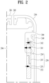
- FIG. 2 shows an antenna for short-range wireless communication such as Wi-Fi and Bluetooth among the antennas of the mobile terminal 100 in accordance with the present disclosure.
- the mobile terminal 100 in accordance with the present disclosure has an antenna for performing Wi-Fi/Bluetooth based wireless communication at the top portion of the mobile terminal 100.
- Wi-Fi WIFI stands for Wireless Fidelity. This is a technology called short-range communication network over which the device can access the wireless Internet within a certain distance using the radio wave or infrared transmission scheme in a site where the access point (AP) is installed.
- the main purpose of Wi-Fi is to allow the user to access information more easily and to allow the user device to coexist with peripheral devices to enhance compatibility therebetween, and to allow wireless access to applications and data, media, and streams.
- the access point (AP) is required. When the AP is available, a device supporting the Wi-Fi captures the reception radio wave and tries to access the Internet.
- the conventional WiFi antenna uses the SISO (serial in serial out scheme), thereby to have a slow transmission rate.
- SISO serial in serial out scheme
- the data transmission amount has increased exponentially by applying the MIMO technology to the WIFI technology.
- Bluetooth uses ISM (Industrial Scientific and Medical) frequency band of 2400 to 2483.5 MHz. The band may be divided into 79 channels to prevent interference between devices. Bluetooth may utilize a frequency band similar to that of WiFi and may perform wireless communication using the same antenna as that of the WiFi.
- ISM International Scientific and Medical
- the present disclosure is characterized in that a Wi-Fi antenna is implemented using two antennas to improve the wireless communication performance based on the Wi-Fi.
- the two antennas may include a first antenna 240 as a portion of the side case and a second antenna 250 sharing a ground line 241 with the first antenna 240 to implement the Wi-Fi antenna.
- a middle frame 290 and a side case 200 are shown.
- the middle frame 290 and the side case 200 are spaced apart from each other. In another example, they may be partially and integrally connected to each other.
- the side case 200 includes antennas 230 and 240 made of a conductive material such as metal, and slits 203 and 204 spacing the antennas 230 and 240 from each other.
- an integrated side case 200 may be produced by injecting a nonconductive material into the slit 203 and 204 between the antennas 230 and 240 in a dual injection scheme, as shown in FIG. 1B and FIG. 1C .
- the first antenna 240 located on the side case among the plurality of antennas is an antenna used for wireless communication based on Wi-Fi and Bluetooth.
- a first end of the first antenna 240 is open, while a second end thereof is connected to the middle frame 290. That is, the middle frame 290 and the first antenna 240 defines a slot whose the first end is opened and the second end is blocked.
- FIG. 3 is a diagram for explaining the operation and performance of the first antenna 240 of the mobile terminal 100 according to an embodiment of the present disclosure.
- FIG. 4 is a diagram for explaining the operation of the second antenna 250 of the mobile terminal 100 and the electric field distribution according to an embodiment of the present disclosure.
- the first antenna 240 in accordance with the present disclosure has an open first end near the slit 204. The second end thereof is connected to the middle frame 290 and thus is grounded.
- a third antenna adjacent to the second antenna 250 has a portion adjacent to the second antenna 250 and connected to the middle frame 290 via the ground line 241.
- the mutual interference between the third antenna and the second antenna 250 may be minimized such that the effect of the adjacent third antenna on the second antenna 250 may be reduced.
- the second end of the first antenna 240 is connected to the middle frame 290.
- the portion thereof connected to the middle frame 290 may serve as a ground line 241.
- an additional ground line 241 may be provided.
- the position of the feeding line 242 near the first end determines the resonance frequency of the first antenna 240.
- the feeding line 242 disposed adjacent to the ground line 241 is further included.
- a current flows from the ground line 241 along the first antenna 240.
- the radiation mainly occurs through the slit 204 and the intensity of the electric field at the slit 204 is the greatest.
- the spacing between the antennas may not be large.
- the first antenna 240 and the second antenna 250 are disposed adjacent to each other.
- the antennas transmitting and receiving signals at different frequency bands are disposed adjacent to each other, there is interference between them.
- the mutual interference between a plurality of antennas operating in the same frequency band may be more severe. Therefore, it is not easy to construct the antennas for transmitting and receiving signals at the same frequency band in the mobile terminal 100 having a small size.
- the second antenna 250 operating at the same frequency as that of the first antenna 240 may have an additional radiator sharing the ground line 241 to avoid mutual interference.
- FIG. 4 is a diagram illustrating a first antenna 240 of a mobile terminal 100 according to an embodiment of the present disclosure, wherein (a) is a perspective view thereof and (b) is a conceptual view schematically showing the first antenna 240 and second antenna 250.
- An end of the second antenna 250 is overlapped in the thickness direction with the slot formed by the first antenna 240 and the middle frame 290 and is spaced from the slot in the backward direction.
- the second antenna 250 may be located on the inner surface of the rear case 102 located on the rear surface of the middle frame 290.
- the second antenna 250 is composed of two patterns as shown in FIG. 4A .
- a first pattern 254 and second pattern 255 may be formed.
- a gap 253 as a separation space between first pattern and 254 second pattern 255 may be defined.
- the ground line 241 shared between the second antenna 250 and the first antenna 240 is connected to the first pattern 254 and the feeding line 252 is connected to the second pattern 255.
- An end of the second antenna 250 is disposed in a superposed manner with the slot formed by the first antenna 240 and the middle frame 290 in the thickness direction of the mobile terminal 100. That is, the second antenna 250 is spaced apart from the first antenna 240 in the back direction of the mobile terminal 100.
- the second antenna 250 may be located on the inner face of the rear case 102 located on the back face of the middle frame 290.
- the second antenna 250 may be realized by injecting the second antenna 250 to the inner face of the rear case 102 or by attaching the patterns thereto.
- the gap 253 serves as a capacitor.
- the left portion of FIG. 4(b) is the first antenna 240 and the right portion thereof is the second antenna 250.
- the first antenna 240 and the second antenna 250 have feeding lines 242 and 252 respectively, while the ground line 241 is shared therebetween.
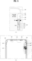
- FIG. 5 is a view for explaining the operation of the second antenna 250 of the mobile terminal 100 and the distribution of the electric field according to an embodiment of the present disclosure.
- (a) is a diagram showing a current flow when power is applied to the feeding line 252 of the second antenna 250.
- the radiator may partially operate as a slot antenna.
- the largest electric field is generated around the gap 253 because a large number of charges accumulate around the gap 253.
- a location from which the main radiation occurs that is, the location where the largest electric field is generated
- the slit 204 adjacent to the first end of the first antenna 240.
- a location from which the main radiation occurs that is, the location where the largest electric field is generated
- the gap 253 in the second antenna 250 is the locations from which the main radiation occurs (that is, the location where the largest electric field is generated) when the first antenna 240 and second antenna 250 operate.
- the second antenna 250 overlaps with the middle frame 290 as the ground, when viewed from the rear.
- the middle frame 290 is overlapped with the second antenna 250, the charges may be caught by the middle frame 290, such that the radiation performance may be deteriorated.
- the first antenna 240 and second antenna 250 may share the ground line 241 such that, with the help of the first antenna 240, the radiation from the second antenna 250 may occur as shown in FIG. 5b .
- the capacitance of the capacitor that is, the amount of the charge collected in the capacitor is determined by the distance between the two conductors and the area of each of the opposite conductors.
- the gap may be formed in a bent shape instead of a straight line, so that the entire length of the gap may be made larger. The larger the amount of the charges accumulated in the gap, the more radiation from the gap may occur.
- the isolation between the second antenna and the first antenna may be larger.
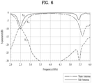
- FIG. 6 is a graph illustrating a mutual interference between the first antenna 240 and the second antenna 250 of a mobile terminal according to an embodiment of the present disclosure.
- Both of the first antenna 240 and second antenna 250 resonate at 2.5GHz and 5GHz.
- the graph has peaks and valley corresponding thereto.
- S 12 which represents the transfer coefficient at the point corresponding to the resonance frequency becomes larger at the resonance frequency, thereby degrading the performance of the first antenna 240 and the second antenna 250.
- the transfer coefficient is greater than -5 dB.
- the transfer coefficient is about -9 dB at 2.5 GHz and is lower than -9 dB at 5 GHz, so that the influence between the first antenna 240 and the second antenna 250 is substantially negligible.
- forming the gap in the second antenna 250 to change the radiation position as described above may reduce the reflection coefficient.
- FIG. 7 is a graph illustrating wireless communication efficiency of the first antenna 240 and the second antenna 250 of the mobile terminal according to an embodiment of the present disclosure.
- the solid line is a graph showing the theoretical radiation efficiency when the impedances of the antennas match with each other (in the ideal state), that is, the reflection coefficients S 11 and S 22 are - ⁇ .
- the dotted line represents the performance of the actually designed antennas. When implementing the actually designed antennas, the impedance matching is not perfect. Thus, the total efficiency is lower than the theoretical value.
- the first antenna 240 and the second antenna 250 both have the resonance frequency correctly located at 2.5 GHz, such that the impedance matching therebetween occurs.
- the actual efficiency is not much lower than the theoretical efficiency.
- the mobile terminal 100 may increase the data transmission rate by having the increased number of Wi-Fi antennas.
- antenna performance can be improved by minimizing interference between the antennas transmitting and receiving signals at the same frequency.
- the performance of the antennas can be secured and the size of the top bezel of the display unit can be reduced.
Landscapes
- Engineering & Computer Science (AREA)
- Signal Processing (AREA)
- Computer Networks & Wireless Communication (AREA)
- Telephone Set Structure (AREA)
- Telephone Function (AREA)
Claims (10)
- Terminal mobile comprenant :un boîtier (102) pour recevoir un composant électronique à l'intérieur ;un cadre intermédiaire (290) monté sur le boîtier (102) ;une carte principale montée sur le boîtier (102) ;une première antenne (240) formant une fente dans le cadre intermédiaire (290), dans lequel la première antenne (240) a une première extrémité espacée du cadre intermédiaire (290), et une seconde extrémité connectée au cadre intermédiaire (290) ;une seconde antenne (250) comportant un premier motif (254) et un second motif (255),dans lequel un interstice (253) est formé entre le premier motif (254) et le second motif (255) ;une première ligne d'alimentation (242) connectée entre la première antenne (240) et la carte principale pour transmettre un signal à celle-ci ;une ligne de masse (241) connectée entre la première antenne (240), le premier motif (254) du second motif (255) et le cadre intermédiaire (290) pour mettre à la masse la première antenne (240) et la seconde antenne (250) ; etune seconde ligne d'alimentation (252) connectée au second motif (255) de la seconde antenne (250),dans lequel au moins une partie de la seconde antenne (250) se superpose avec la fente.
- Terminal mobile selon la revendication 1, dans lequel la première antenne (240) s'étend dans une première direction, dans lequel le premier motif (254) et le second motif (255) sont agencés dans la première direction.
- Terminal mobile selon la revendication 2, dans lequel la ligne de masse (241) est placée entre la première ligne d'alimentation (242) et la seconde ligne d'alimentation (252) dans la première direction.
- Terminal mobile selon la revendication 1, dans lequel la première extrémité de la première antenne (240) et l'interstice (253) de la seconde antenne (250) ne se superposent pas l'un avec l'autre.
- Terminal mobile selon la revendication 1, dans lequel l'interstice (253) de la seconde antenne (250) s'étend sous une forme courbe.
- Terminal mobile selon la revendication 1, dans lequel le premier motif (254) de la seconde antenne (250) se superpose avec la fente.
- Terminal mobile selon la revendication 1, dans lequel au moins une partie de la seconde antenne (250) se superpose avec le cadre intermédiaire (290) et est située sur une face arrière du boîtier (102).
- Terminal mobile selon la revendication 1, dans lequel le boîtier (102) comporte un boîtier latéral (200), dans lequel la première antenne (240) définit une partie du boîtier latéral (200) exposée à un extérieur.
- Terminal mobile selon la revendication 1, dans lequel le boîtier (102) comporte un boîtier (102) arrière fait d'un matériau non métallique, dans lequel la seconde antenne (250) comporte un motif conducteur fixé au boîtier (102) arrière.
- Terminal mobile selon la revendication 1, dans lequel l'interstice (253) se superpose avec le cadre intermédiaire (290).
Applications Claiming Priority (1)
| Application Number | Priority Date | Filing Date | Title |
|---|---|---|---|
| PCT/KR2017/000942 WO2018139691A1 (fr) | 2017-01-26 | 2017-01-26 | Terminal mobile |
Publications (3)
| Publication Number | Publication Date |
|---|---|
| EP3576384A1 EP3576384A1 (fr) | 2019-12-04 |
| EP3576384A4 EP3576384A4 (fr) | 2020-09-16 |
| EP3576384B1 true EP3576384B1 (fr) | 2022-01-19 |
Family
ID=62979498
Family Applications (1)
| Application Number | Title | Priority Date | Filing Date |
|---|---|---|---|
| EP17893914.6A Active EP3576384B1 (fr) | 2017-01-26 | 2017-01-26 | Terminal mobile |
Country Status (5)
| Country | Link |
|---|---|
| US (1) | US10910697B2 (fr) |
| EP (1) | EP3576384B1 (fr) |
| KR (1) | KR102174643B1 (fr) |
| CN (1) | CN110226320B (fr) |
| WO (1) | WO2018139691A1 (fr) |
Families Citing this family (7)
| Publication number | Priority date | Publication date | Assignee | Title |
|---|---|---|---|---|
| CN108600460B (zh) * | 2018-05-07 | 2020-10-09 | 维沃移动通信有限公司 | 一种移动终端 |
| BR112020023108A2 (pt) * | 2018-05-15 | 2021-02-02 | Huawei Technologies Co., Ltd. | sistema de antena e dispositivo terminal |
| KR20210079998A (ko) * | 2019-12-20 | 2021-06-30 | 삼성전자주식회사 | 안테나 및 이를 포함하는 전자 장치 |
| KR20220061572A (ko) | 2020-11-06 | 2022-05-13 | 삼성전자주식회사 | 안테나를 포함하는 전자 장치 |
| KR20240008834A (ko) * | 2021-05-17 | 2024-01-19 | 엘지전자 주식회사 | 차량에 탑재되는 안테나 시스템 |
| KR20230027914A (ko) * | 2021-08-20 | 2023-02-28 | 삼성전자주식회사 | 안테나를 포함하는 전자 장치 |
| WO2024117723A1 (fr) * | 2022-11-28 | 2024-06-06 | 삼성전자 주식회사 | Dispositif électronique comprenant une antenne |
Family Cites Families (21)
| Publication number | Priority date | Publication date | Assignee | Title |
|---|---|---|---|---|
| JPH0633693B2 (ja) * | 1986-11-18 | 1994-05-02 | 東洋シャッター株式会社 | オ−バ−ドア |
| DE10039427A1 (de) | 2000-08-11 | 2002-02-21 | Siemens Ag | Antennenanordnung eines mobilen Kommunikationsendgerätes, insbesondere eines Mobiltelefons |
| CN100347992C (zh) | 2004-07-09 | 2007-11-07 | 清华大学 | 实现线速对数据流按规则库近似匹配的可配置的硬件结构 |
| CN100353610C (zh) * | 2004-07-22 | 2007-12-05 | 上海交通大学 | 小型高隔离度平面双天线 |
| JP5741200B2 (ja) | 2011-05-11 | 2015-07-01 | 富士通株式会社 | 通信装置 |
| CN102509881A (zh) | 2011-11-18 | 2012-06-20 | 鸿富锦精密工业(深圳)有限公司 | 具有多天线的电子装置 |
| EP3525285B1 (fr) | 2012-06-21 | 2021-05-12 | LG Electronics Inc. | Dispositif d'antenne et terminal portable en étant doté |
| JP6033693B2 (ja) * | 2013-01-22 | 2016-11-30 | 京セラ株式会社 | 電子機器 |
| KR102025706B1 (ko) * | 2013-01-30 | 2019-09-26 | 삼성전자주식회사 | 휴대용 단말기의 안테나 장치 |
| US20160254589A1 (en) * | 2013-07-17 | 2016-09-01 | AQ Corporation | Near field communication antenna and smartphone having same antenna |
| CN103441330A (zh) | 2013-08-06 | 2013-12-11 | 华为终端有限公司 | 无线通信设备 |
| CN104425885B (zh) * | 2013-09-06 | 2018-03-06 | 华为终端(东莞)有限公司 | 天线装置及移动终端 |
| KR20160067541A (ko) * | 2014-12-04 | 2016-06-14 | 엘지전자 주식회사 | 안테나 모듈 및 이를 이용한 이동 단말기 |
| US9735829B2 (en) | 2015-03-18 | 2017-08-15 | Samsung Electro-Mechanics Co., Ltd. | Electronic device including multi-feed, multi-band antenna using external conductor |
| KR101640709B1 (ko) * | 2015-04-06 | 2016-07-18 | 한양대학교 산학협력단 | 고감도 그라운드 방사 안테나 |
| US9866252B2 (en) * | 2015-04-22 | 2018-01-09 | Lg Electronics Inc. | Mobile terminal |
| KR102364413B1 (ko) * | 2015-05-27 | 2022-02-17 | 삼성전자주식회사 | 안테나 장치를 포함하는 전자 장치 |
| CN105305072B (zh) | 2015-09-18 | 2018-05-18 | 广东欧珀移动通信有限公司 | 一种天线及电子设备 |
| KR101622731B1 (ko) * | 2016-01-11 | 2016-05-19 | 엘지전자 주식회사 | 이동 단말기 |
| WO2017141601A1 (fr) * | 2016-02-18 | 2017-08-24 | パナソニックIpマネジメント株式会社 | Dispositif d'antenne et appareil électronique |
| CN105958201B (zh) | 2016-04-27 | 2019-12-24 | 上海安费诺永亿通讯电子有限公司 | 一种金属框手机天线 |
-
2017
- 2017-01-26 KR KR1020197020578A patent/KR102174643B1/ko active IP Right Grant
- 2017-01-26 CN CN201780084799.9A patent/CN110226320B/zh active Active
- 2017-01-26 WO PCT/KR2017/000942 patent/WO2018139691A1/fr unknown
- 2017-01-26 US US16/479,072 patent/US10910697B2/en active Active
- 2017-01-26 EP EP17893914.6A patent/EP3576384B1/fr active Active
Also Published As
| Publication number | Publication date |
|---|---|
| KR102174643B1 (ko) | 2020-11-05 |
| CN110226320B (zh) | 2021-01-12 |
| WO2018139691A1 (fr) | 2018-08-02 |
| EP3576384A1 (fr) | 2019-12-04 |
| CN110226320A (zh) | 2019-09-10 |
| US10910697B2 (en) | 2021-02-02 |
| EP3576384A4 (fr) | 2020-09-16 |
| US20200014093A1 (en) | 2020-01-09 |
| KR20190090870A (ko) | 2019-08-02 |
Similar Documents
| Publication | Publication Date | Title |
|---|---|---|
| US11600905B2 (en) | Mobile terminal | |
| US11024947B2 (en) | Mobile terminal | |
| US11362699B2 (en) | Mobile terminal | |
| US10312573B2 (en) | Mobile terminal | |
| US9755298B2 (en) | Antenna module and mobile terminal having the same | |
| EP3041083B1 (fr) | Module d'antenne et terminal mobile doté de celui-ci | |
| EP3576384B1 (fr) | Terminal mobile | |
| US20190036231A1 (en) | Array antenna and mobile terminal | |
| US20190115653A1 (en) | Mobile terminal | |
| US10840582B2 (en) | Mobile terminal | |
| US10879593B2 (en) | Mobile terminal | |
| US10976860B2 (en) | Electronic device | |
| US10700417B1 (en) | Mobile terminal | |
| EP3451636A1 (fr) | Terminal mobile | |
| US10341477B2 (en) | Mobile terminal |
Legal Events
| Date | Code | Title | Description |
|---|---|---|---|
| STAA | Information on the status of an ep patent application or granted ep patent |
Free format text: STATUS: THE INTERNATIONAL PUBLICATION HAS BEEN MADE |
|
| PUAI | Public reference made under article 153(3) epc to a published international application that has entered the european phase |
Free format text: ORIGINAL CODE: 0009012 |
|
| STAA | Information on the status of an ep patent application or granted ep patent |
Free format text: STATUS: REQUEST FOR EXAMINATION WAS MADE |
|
| 17P | Request for examination filed |
Effective date: 20190821 |
|
| AK | Designated contracting states |
Kind code of ref document: A1 Designated state(s): AL AT BE BG CH CY CZ DE DK EE ES FI FR GB GR HR HU IE IS IT LI LT LU LV MC MK MT NL NO PL PT RO RS SE SI SK SM TR |
|
| AX | Request for extension of the european patent |
Extension state: BA ME |
|
| DAV | Request for validation of the european patent (deleted) | ||
| DAX | Request for extension of the european patent (deleted) | ||
| A4 | Supplementary search report drawn up and despatched |
Effective date: 20200814 |
|
| RIC1 | Information provided on ipc code assigned before grant |
Ipc: H04M 1/02 20060101AFI20200810BHEP Ipc: H01Q 1/24 20060101ALI20200810BHEP Ipc: H01Q 1/52 20060101ALI20200810BHEP |
|
| GRAP | Despatch of communication of intention to grant a patent |
Free format text: ORIGINAL CODE: EPIDOSNIGR1 |
|
| STAA | Information on the status of an ep patent application or granted ep patent |
Free format text: STATUS: GRANT OF PATENT IS INTENDED |
|
| RIC1 | Information provided on ipc code assigned before grant |
Ipc: H04M 1/02 20060101AFI20210729BHEP Ipc: H01Q 1/52 20060101ALI20210729BHEP Ipc: H01Q 1/24 20060101ALI20210729BHEP Ipc: H01Q 1/44 20060101ALI20210729BHEP Ipc: H01Q 13/10 20060101ALI20210729BHEP |
|
| INTG | Intention to grant announced |
Effective date: 20210818 |
|
| GRAS | Grant fee paid |
Free format text: ORIGINAL CODE: EPIDOSNIGR3 |
|
| GRAA | (expected) grant |
Free format text: ORIGINAL CODE: 0009210 |
|
| STAA | Information on the status of an ep patent application or granted ep patent |
Free format text: STATUS: THE PATENT HAS BEEN GRANTED |
|
| AK | Designated contracting states |
Kind code of ref document: B1 Designated state(s): AL AT BE BG CH CY CZ DE DK EE ES FI FR GB GR HR HU IE IS IT LI LT LU LV MC MK MT NL NO PL PT RO RS SE SI SK SM TR |
|
| REG | Reference to a national code |
Ref country code: GB Ref legal event code: FG4D |
|
| REG | Reference to a national code |
Ref country code: CH Ref legal event code: EP |
|
| REG | Reference to a national code |
Ref country code: AT Ref legal event code: REF Ref document number: 1464442 Country of ref document: AT Kind code of ref document: T Effective date: 20220215 |
|
| REG | Reference to a national code |
Ref country code: IE Ref legal event code: FG4D |
|
| REG | Reference to a national code |
Ref country code: DE Ref legal event code: R096 Ref document number: 602017052614 Country of ref document: DE |
|
| REG | Reference to a national code |
Ref country code: LT Ref legal event code: MG9D |
|
| REG | Reference to a national code |
Ref country code: NL Ref legal event code: MP Effective date: 20220119 |
|
| REG | Reference to a national code |
Ref country code: AT Ref legal event code: MK05 Ref document number: 1464442 Country of ref document: AT Kind code of ref document: T Effective date: 20220119 |
|
| PG25 | Lapsed in a contracting state [announced via postgrant information from national office to epo] |
Ref country code: NL Free format text: LAPSE BECAUSE OF FAILURE TO SUBMIT A TRANSLATION OF THE DESCRIPTION OR TO PAY THE FEE WITHIN THE PRESCRIBED TIME-LIMIT Effective date: 20220119 |
|
| PG25 | Lapsed in a contracting state [announced via postgrant information from national office to epo] |
Ref country code: SE Free format text: LAPSE BECAUSE OF FAILURE TO SUBMIT A TRANSLATION OF THE DESCRIPTION OR TO PAY THE FEE WITHIN THE PRESCRIBED TIME-LIMIT Effective date: 20220119 Ref country code: RS Free format text: LAPSE BECAUSE OF FAILURE TO SUBMIT A TRANSLATION OF THE DESCRIPTION OR TO PAY THE FEE WITHIN THE PRESCRIBED TIME-LIMIT Effective date: 20220119 Ref country code: PT Free format text: LAPSE BECAUSE OF FAILURE TO SUBMIT A TRANSLATION OF THE DESCRIPTION OR TO PAY THE FEE WITHIN THE PRESCRIBED TIME-LIMIT Effective date: 20220519 Ref country code: NO Free format text: LAPSE BECAUSE OF FAILURE TO SUBMIT A TRANSLATION OF THE DESCRIPTION OR TO PAY THE FEE WITHIN THE PRESCRIBED TIME-LIMIT Effective date: 20220419 Ref country code: LT Free format text: LAPSE BECAUSE OF FAILURE TO SUBMIT A TRANSLATION OF THE DESCRIPTION OR TO PAY THE FEE WITHIN THE PRESCRIBED TIME-LIMIT Effective date: 20220119 Ref country code: HR Free format text: LAPSE BECAUSE OF FAILURE TO SUBMIT A TRANSLATION OF THE DESCRIPTION OR TO PAY THE FEE WITHIN THE PRESCRIBED TIME-LIMIT Effective date: 20220119 Ref country code: ES Free format text: LAPSE BECAUSE OF FAILURE TO SUBMIT A TRANSLATION OF THE DESCRIPTION OR TO PAY THE FEE WITHIN THE PRESCRIBED TIME-LIMIT Effective date: 20220119 Ref country code: BG Free format text: LAPSE BECAUSE OF FAILURE TO SUBMIT A TRANSLATION OF THE DESCRIPTION OR TO PAY THE FEE WITHIN THE PRESCRIBED TIME-LIMIT Effective date: 20220419 |
|
| PG25 | Lapsed in a contracting state [announced via postgrant information from national office to epo] |
Ref country code: PL Free format text: LAPSE BECAUSE OF FAILURE TO SUBMIT A TRANSLATION OF THE DESCRIPTION OR TO PAY THE FEE WITHIN THE PRESCRIBED TIME-LIMIT Effective date: 20220119 Ref country code: LV Free format text: LAPSE BECAUSE OF FAILURE TO SUBMIT A TRANSLATION OF THE DESCRIPTION OR TO PAY THE FEE WITHIN THE PRESCRIBED TIME-LIMIT Effective date: 20220119 Ref country code: GR Free format text: LAPSE BECAUSE OF FAILURE TO SUBMIT A TRANSLATION OF THE DESCRIPTION OR TO PAY THE FEE WITHIN THE PRESCRIBED TIME-LIMIT Effective date: 20220420 Ref country code: FI Free format text: LAPSE BECAUSE OF FAILURE TO SUBMIT A TRANSLATION OF THE DESCRIPTION OR TO PAY THE FEE WITHIN THE PRESCRIBED TIME-LIMIT Effective date: 20220119 Ref country code: AT Free format text: LAPSE BECAUSE OF FAILURE TO SUBMIT A TRANSLATION OF THE DESCRIPTION OR TO PAY THE FEE WITHIN THE PRESCRIBED TIME-LIMIT Effective date: 20220119 |
|
| REG | Reference to a national code |
Ref country code: CH Ref legal event code: PL |
|
| PG25 | Lapsed in a contracting state [announced via postgrant information from national office to epo] |
Ref country code: IS Free format text: LAPSE BECAUSE OF FAILURE TO SUBMIT A TRANSLATION OF THE DESCRIPTION OR TO PAY THE FEE WITHIN THE PRESCRIBED TIME-LIMIT Effective date: 20220519 |
|
| REG | Reference to a national code |
Ref country code: BE Ref legal event code: MM Effective date: 20220131 |
|
| REG | Reference to a national code |
Ref country code: DE Ref legal event code: R097 Ref document number: 602017052614 Country of ref document: DE |
|
| PG25 | Lapsed in a contracting state [announced via postgrant information from national office to epo] |
Ref country code: SM Free format text: LAPSE BECAUSE OF FAILURE TO SUBMIT A TRANSLATION OF THE DESCRIPTION OR TO PAY THE FEE WITHIN THE PRESCRIBED TIME-LIMIT Effective date: 20220119 Ref country code: SK Free format text: LAPSE BECAUSE OF FAILURE TO SUBMIT A TRANSLATION OF THE DESCRIPTION OR TO PAY THE FEE WITHIN THE PRESCRIBED TIME-LIMIT Effective date: 20220119 Ref country code: RO Free format text: LAPSE BECAUSE OF FAILURE TO SUBMIT A TRANSLATION OF THE DESCRIPTION OR TO PAY THE FEE WITHIN THE PRESCRIBED TIME-LIMIT Effective date: 20220119 Ref country code: MC Free format text: LAPSE BECAUSE OF FAILURE TO SUBMIT A TRANSLATION OF THE DESCRIPTION OR TO PAY THE FEE WITHIN THE PRESCRIBED TIME-LIMIT Effective date: 20220119 Ref country code: LU Free format text: LAPSE BECAUSE OF NON-PAYMENT OF DUE FEES Effective date: 20220126 Ref country code: EE Free format text: LAPSE BECAUSE OF FAILURE TO SUBMIT A TRANSLATION OF THE DESCRIPTION OR TO PAY THE FEE WITHIN THE PRESCRIBED TIME-LIMIT Effective date: 20220119 Ref country code: DK Free format text: LAPSE BECAUSE OF FAILURE TO SUBMIT A TRANSLATION OF THE DESCRIPTION OR TO PAY THE FEE WITHIN THE PRESCRIBED TIME-LIMIT Effective date: 20220119 Ref country code: CZ Free format text: LAPSE BECAUSE OF FAILURE TO SUBMIT A TRANSLATION OF THE DESCRIPTION OR TO PAY THE FEE WITHIN THE PRESCRIBED TIME-LIMIT Effective date: 20220119 |
|
| PLBE | No opposition filed within time limit |
Free format text: ORIGINAL CODE: 0009261 |
|
| STAA | Information on the status of an ep patent application or granted ep patent |
Free format text: STATUS: NO OPPOSITION FILED WITHIN TIME LIMIT |
|
| PG25 | Lapsed in a contracting state [announced via postgrant information from national office to epo] |
Ref country code: BE Free format text: LAPSE BECAUSE OF NON-PAYMENT OF DUE FEES Effective date: 20220131 Ref country code: AL Free format text: LAPSE BECAUSE OF FAILURE TO SUBMIT A TRANSLATION OF THE DESCRIPTION OR TO PAY THE FEE WITHIN THE PRESCRIBED TIME-LIMIT Effective date: 20220119 |
|
| 26N | No opposition filed |
Effective date: 20221020 |
|
| PG25 | Lapsed in a contracting state [announced via postgrant information from national office to epo] |
Ref country code: LI Free format text: LAPSE BECAUSE OF NON-PAYMENT OF DUE FEES Effective date: 20220131 Ref country code: CH Free format text: LAPSE BECAUSE OF NON-PAYMENT OF DUE FEES Effective date: 20220131 |
|
| PG25 | Lapsed in a contracting state [announced via postgrant information from national office to epo] |
Ref country code: IE Free format text: LAPSE BECAUSE OF NON-PAYMENT OF DUE FEES Effective date: 20220126 |
|
| PG25 | Lapsed in a contracting state [announced via postgrant information from national office to epo] |
Ref country code: SI Free format text: LAPSE BECAUSE OF FAILURE TO SUBMIT A TRANSLATION OF THE DESCRIPTION OR TO PAY THE FEE WITHIN THE PRESCRIBED TIME-LIMIT Effective date: 20220119 |
|
| PG25 | Lapsed in a contracting state [announced via postgrant information from national office to epo] |
Ref country code: IT Free format text: LAPSE BECAUSE OF FAILURE TO SUBMIT A TRANSLATION OF THE DESCRIPTION OR TO PAY THE FEE WITHIN THE PRESCRIBED TIME-LIMIT Effective date: 20220119 |
|
| PGFP | Annual fee paid to national office [announced via postgrant information from national office to epo] |
Ref country code: GB Payment date: 20231207 Year of fee payment: 8 |
|
| PGFP | Annual fee paid to national office [announced via postgrant information from national office to epo] |
Ref country code: FR Payment date: 20231206 Year of fee payment: 8 |
|
| PG25 | Lapsed in a contracting state [announced via postgrant information from national office to epo] |
Ref country code: MK Free format text: LAPSE BECAUSE OF FAILURE TO SUBMIT A TRANSLATION OF THE DESCRIPTION OR TO PAY THE FEE WITHIN THE PRESCRIBED TIME-LIMIT Effective date: 20220119 Ref country code: CY Free format text: LAPSE BECAUSE OF FAILURE TO SUBMIT A TRANSLATION OF THE DESCRIPTION OR TO PAY THE FEE WITHIN THE PRESCRIBED TIME-LIMIT Effective date: 20220119 |
|
| PGFP | Annual fee paid to national office [announced via postgrant information from national office to epo] |
Ref country code: DE Payment date: 20231205 Year of fee payment: 8 |
|
| PG25 | Lapsed in a contracting state [announced via postgrant information from national office to epo] |
Ref country code: HU Free format text: LAPSE BECAUSE OF FAILURE TO SUBMIT A TRANSLATION OF THE DESCRIPTION OR TO PAY THE FEE WITHIN THE PRESCRIBED TIME-LIMIT; INVALID AB INITIO Effective date: 20170126 |
|
| PG25 | Lapsed in a contracting state [announced via postgrant information from national office to epo] |
Ref country code: TR Free format text: LAPSE BECAUSE OF FAILURE TO SUBMIT A TRANSLATION OF THE DESCRIPTION OR TO PAY THE FEE WITHIN THE PRESCRIBED TIME-LIMIT Effective date: 20220119 |