EP3576121B1 - Schalter mit struktur zur wasserabdichtung und verhinderung von leichten lecks - Google Patents
Schalter mit struktur zur wasserabdichtung und verhinderung von leichten lecks Download PDFInfo
- Publication number
- EP3576121B1 EP3576121B1 EP17893897.3A EP17893897A EP3576121B1 EP 3576121 B1 EP3576121 B1 EP 3576121B1 EP 17893897 A EP17893897 A EP 17893897A EP 3576121 B1 EP3576121 B1 EP 3576121B1
- Authority
- EP
- European Patent Office
- Prior art keywords
- switch
- light emitting
- emitting member
- light
- cover plate
- Prior art date
- Legal status (The legal status is an assumption and is not a legal conclusion. Google has not performed a legal analysis and makes no representation as to the accuracy of the status listed.)
- Active
Links
Images




Classifications
-
- H—ELECTRICITY
- H01—ELECTRIC ELEMENTS
- H01H—ELECTRIC SWITCHES; RELAYS; SELECTORS; EMERGENCY PROTECTIVE DEVICES
- H01H13/00—Switches having rectilinearly-movable operating part or parts adapted for pushing or pulling in one direction only, e.g. push-button switch
- H01H13/02—Details
- H01H13/04—Cases; Covers
- H01H13/06—Dustproof, splashproof, drip-proof, waterproof or flameproof casings
-
- H—ELECTRICITY
- H01—ELECTRIC ELEMENTS
- H01H—ELECTRIC SWITCHES; RELAYS; SELECTORS; EMERGENCY PROTECTIVE DEVICES
- H01H13/00—Switches having rectilinearly-movable operating part or parts adapted for pushing or pulling in one direction only, e.g. push-button switch
- H01H13/02—Details
- H01H13/023—Light-emitting indicators
-
- H—ELECTRICITY
- H01—ELECTRIC ELEMENTS
- H01H—ELECTRIC SWITCHES; RELAYS; SELECTORS; EMERGENCY PROTECTIVE DEVICES
- H01H13/00—Switches having rectilinearly-movable operating part or parts adapted for pushing or pulling in one direction only, e.g. push-button switch
- H01H13/02—Details
- H01H13/12—Movable parts; Contacts mounted thereon
- H01H13/14—Operating parts, e.g. push-button
-
- H—ELECTRICITY
- H01—ELECTRIC ELEMENTS
- H01H—ELECTRIC SWITCHES; RELAYS; SELECTORS; EMERGENCY PROTECTIVE DEVICES
- H01H13/00—Switches having rectilinearly-movable operating part or parts adapted for pushing or pulling in one direction only, e.g. push-button switch
- H01H13/02—Details
- H01H13/26—Snap-action arrangements depending upon deformation of elastic members
-
- H—ELECTRICITY
- H01—ELECTRIC ELEMENTS
- H01H—ELECTRIC SWITCHES; RELAYS; SELECTORS; EMERGENCY PROTECTIVE DEVICES
- H01H13/00—Switches having rectilinearly-movable operating part or parts adapted for pushing or pulling in one direction only, e.g. push-button switch
- H01H13/02—Details
- H01H13/26—Snap-action arrangements depending upon deformation of elastic members
- H01H13/48—Snap-action arrangements depending upon deformation of elastic members using buckling of disc springs
-
- H—ELECTRICITY
- H01—ELECTRIC ELEMENTS
- H01H—ELECTRIC SWITCHES; RELAYS; SELECTORS; EMERGENCY PROTECTIVE DEVICES
- H01H13/00—Switches having rectilinearly-movable operating part or parts adapted for pushing or pulling in one direction only, e.g. push-button switch
- H01H13/70—Switches having rectilinearly-movable operating part or parts adapted for pushing or pulling in one direction only, e.g. push-button switch having a plurality of operating members associated with different sets of contacts, e.g. keyboard
- H01H13/83—Switches having rectilinearly-movable operating part or parts adapted for pushing or pulling in one direction only, e.g. push-button switch having a plurality of operating members associated with different sets of contacts, e.g. keyboard characterised by legends, e.g. Braille, liquid crystal displays, light emitting or optical elements
-
- H—ELECTRICITY
- H01—ELECTRIC ELEMENTS
- H01H—ELECTRIC SWITCHES; RELAYS; SELECTORS; EMERGENCY PROTECTIVE DEVICES
- H01H23/00—Tumbler or rocker switches, i.e. switches characterised by being operated by rocking an operating member in the form of a rocker button
- H01H23/02—Details
- H01H23/025—Light-emitting indicators
-
- H—ELECTRICITY
- H01—ELECTRIC ELEMENTS
- H01H—ELECTRIC SWITCHES; RELAYS; SELECTORS; EMERGENCY PROTECTIVE DEVICES
- H01H9/00—Details of switching devices, not covered by groups H01H1/00 - H01H7/00
- H01H9/16—Indicators for switching condition, e.g. "on" or "off"
- H01H9/161—Indicators for switching condition, e.g. "on" or "off" comprising light emitting elements
-
- H—ELECTRICITY
- H01—ELECTRIC ELEMENTS
- H01H—ELECTRIC SWITCHES; RELAYS; SELECTORS; EMERGENCY PROTECTIVE DEVICES
- H01H13/00—Switches having rectilinearly-movable operating part or parts adapted for pushing or pulling in one direction only, e.g. push-button switch
- H01H13/70—Switches having rectilinearly-movable operating part or parts adapted for pushing or pulling in one direction only, e.g. push-button switch having a plurality of operating members associated with different sets of contacts, e.g. keyboard
- H01H13/86—Switches having rectilinearly-movable operating part or parts adapted for pushing or pulling in one direction only, e.g. push-button switch having a plurality of operating members associated with different sets of contacts, e.g. keyboard characterised by the casing, e.g. sealed casings or casings reducible in size
-
- H—ELECTRICITY
- H01—ELECTRIC ELEMENTS
- H01H—ELECTRIC SWITCHES; RELAYS; SELECTORS; EMERGENCY PROTECTIVE DEVICES
- H01H2219/00—Legends
- H01H2219/054—Optical elements
- H01H2219/064—Optical isolation of switch sites
-
- H—ELECTRICITY
- H01—ELECTRIC ELEMENTS
- H01H—ELECTRIC SWITCHES; RELAYS; SELECTORS; EMERGENCY PROTECTIVE DEVICES
- H01H2223/00—Casings
- H01H2223/002—Casings sealed
-
- H—ELECTRICITY
- H01—ELECTRIC ELEMENTS
- H01H—ELECTRIC SWITCHES; RELAYS; SELECTORS; EMERGENCY PROTECTIVE DEVICES
- H01H2223/00—Casings
- H01H2223/002—Casings sealed
- H01H2223/003—Membrane embracing all keys
Definitions
- the present invention relates to a switch including a waterproof and light leak prevention structure, and more specifically to a switch including a light emitting member and a push switch on a mount, and including a structure that efficiently prevents a liquid or foreign matter from entering the inside from the outside, and prevents light emitted from the light emitting member from leaking in an unintended direction.
- a light emitting member or a push switch is provided on a mount, as illustrated in FIG. 1 and FIG. 2 .
- a conventional switch 10 includes a light emitting member 13 on a mount 12.
- the light emitting member 13 emits light in response to a predetermined control signal and emits light in the direction of the push switch knob 11.
- a light leak prevention structure 15 is further provided in a housing 14.
- a light leak prevention structure 25 is additionally provided inside the housing 24 to prevent light emitted from a light emitting member 23 from leaking in an unintended direction.
- US 2012/0090969 A1 shows a keyboard including a membrane circuit board, a luminous key, a light-emitting element and a plastic film layer.
- the luminous key has a keycap with a light-transmissible part.
- the light-emitting element is disposed on the membrane circuit board and arranged under the membrane circuit board for emitting a light beam.
- the plastic film layer is disposed on the membrane circuit board, and includes a convex structure, which is integrally formed with the plastic film layer.
- the light-emitting element is enclosed by the convex structure.
- the convex structure has a light-transmissible zone aligned with the light-emitting element.
- JP H01 154414 A shows a contact rubber with a light shielding paint.
- US 2016/0336124 A1 shows a key including a light guide positioned below a keycap.
- the light guide includes one or more sidewalls that exhibit high internal reflection.
- JP 2010 003592 A shows a switch according to the preamble of claim 1, which is provided with push knobs and a lens which guides light from a light source to the push knobs and illuminates the push knobs from the rear side.
- the lens is constituted of a body on the upper side of which the outgoing face of light is provided and an extension part of which the incident face of light is arranged at a position separated from the body and which guides light entered from the incident face to the body.
- a cylindrical wall to surround an optical path is installed in a range from the light source to the incident face of the lens along the optical path of the light emitted from the light source.
- Patent Document 1 Korean Laid-Open Patent Application Publication No. 10-2006-0032064 (Publication date: April 14, 2006 )
- the present invention is intended to provide a switch including a structure that efficiently prevents light emitted from a light emitting member inside the switch from leaking out and efficiently prevents foreign matter from entering the inside from the outside.
- a switch according to one aspect of the present invention is a switch according to claim 1.
- the cover plate is made of a flexible material having a predetermined restoring force.
- the material of the cover plate is made of rubber, for example.
- the rubber dome includes a pressing contact portion configured to be displaced downward by receiving a push operation of a user and having a predetermined area in a plan view, a support portion extending by a predetermined height from an upper surface of the cover plate and is joined with an outer peripheral surface of the pressing contact portion, and a pressing projection portion projecting by a predetermined length from a lower surface of the pressing contact portion, and configured to push the push switch along with the downward displacement of the pressing contact portion, thereby implementing a switching operation.
- the light emitting member cover is made of, for example, a transparent material.
- the light emitting member cover is joined together with, for example, an inside of the light leakage prevention protrusion.
- a bent portion configured to surround at least part of both ends of the mount is formed at both ends of the cover plate.
- a switch of the present invention by providing a rubber dome, a light emitting member cover, and a cover plate including and a light leak prevention protrusion, light emitted from the light emitting member is prevented from leaking out, and foreign matter is prevented from entering the inside from the outside.
- a switch of the present invention by providing a cover plate made of a flexible material having a predetermined elastic restoring force, push switching that flexibly responds to a user's pushing operation is implemented, and because shock absorption is performed against an external force applied from the outside and the like, the durability of the switch is significantly improved.
- a switch of the present invention by forming a rubber dome, a light emitting member cover, and a light leak prevention protrusion integrally, foreign matter is prevented from entering the inside from the outside.
- a switch of the present invention by providing a rubber dome including a pressing contact part, a support part, and a pressing projection part having a particular structure, switching that efficiently conveys a user's pushing operation is achieved.
- a switch of the present invention because a liquid or foreign matter is prevented from entering the inside from the outside by joining a pressing contact portion and a support portion together and forming a sealed space inside the rubber dome, the push switch can be protected, and a stable push switch operation can be ensured.
- a light emitting member cover made of a transparent material at a particular location a light emitting member can be protected from a liquid or foreign matter that may enter from the outside.
- a switch of the present invention by providing a light leak prevention projection formed at a height corresponding to a height of the rubber dome projecting upward, light emitted from the light emitting member can be efficiently prevented from leaking out.
- a waterproof and light leak prevention structure is stably implemented because the cover plate and the mount are stably adhered to each other.
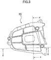
- FIG. 3 is a plan view illustrating a switch according to an embodiment of the present invention.
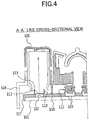
- FIG. 4 is a cross-sectional view of the A-A' line in FIG. 3
- FIG. 5 is a cross-sectional view of the B-B' line in FIG. 3 .
- FIG. 6 is a perspective view illustrating a cover plate according to an embodiment of the present invention.
- a switch 100 can efficiently prevent light emitted from a light emitting member 102 from leaking out, and prevent foreign matter from entering the inside from the outside by providing the switch 100 including the light emitting member 102 and a push switch 103 on a mount 101, and providing a cover plate 110 including a rubber dome 111, a light emitting member cover 112, and a light leak prevention projection 113 having a specific structure.
- the switch 100 is provided on the mount 101, and includes the cover plate 110 structured to cover the light emitting member 102 and the push switch 103.
- the cover plate 110 according to the present embodiment is preferably made of a flexible material having a predetermined elastic restoring force, and for example, the material is made of rubber.
- the material of the cover plate 110 is rubber, it is most preferable from the viewpoint of simultaneously obtaining waterproof and insulating effects.
- the switch 100 of the present invention by providing the cover plate 110 made of a flexible material having a predetermined elastic restoring force, push switching that flexibly responds to a user's pushing operation is implemented, and the durability of the switch is greatly improved because shock absorption works against an external force applied from the outside.
- the rubber dome 111, the light emitting member cover 112, and the light leak prevention protrusion 113 are formed on the cover plate 110, but are preferably integrally formed.
- the switch 100 of the present invention by integrally forming the rubber dome 111, the light emitting member cover 112 and the light leak protrusion 113, foreign matter can be efficiently prevented from entering the inside from the outside.
- the rubber dome 111 is located at a position corresponding to the push switch 103, and includes a pressing contact portion 114, a support portion 115, and a pressing projection portion 116 having a particular structure.
- the pressing contact portion 114 is displaced downward in response to a user's pushing operation, and has a predetermined area in a plane view.
- the support portion 115 is extended by a predetermined height from the upper surface of the cover plate 110 and has a structure integrated with the outer peripheral surface of the pressing contact portion 114.
- the support portion 115 is preferably made of a flexible material having a predetermined elastic restoring force. Specifically, when the pressing contact portion 114 is displaced downward, the support portion 115 is deformed, and when the user's push operation is released, the elastic restoring force of the support portion 115 causes the pressing contact portion 114 to return to its original position.
- the pressing projection portion 116 projects a predetermined length from the lower surface of the pressing contact portion 114, and presses the push switch 103 by moving the pressing contact portion 114 downward, thereby achieving a switching operation.
- the switch 100 of the present invention by providing the rubber dome 111 including the pressing contact portion 114, the support portion 115, and the pressing projection portion 116 having the particular structure, switching that efficiently transmits the user's pushing operation can be achieved.
- the pressing contact portion 114 and the support portion 115 are joined together, thereby forming a space within the rubber dome 111 having a sealed structure.
- the push switch 103 by joining the pressing contact portion 114 and the support portion 115 together and forming a sealed space structure inside, the push switch 103 can be protected, and a stable push switching operation can be ensured because a liquid or foreign matter is efficiently prevented from entering the space including the push switch 103.
- the light emitting member cover 112 has a structure that covers the light emitting member 102 at a predetermined distance from the upper surface of the light emitting member 102.
- the light emitting member cover 112 is made of a transparent material, light emitted from the light emitting member 102 is emitted in the intended direction.
- the switch 100 of the present invention in addition to being made of a transparent material, by providing the light emitting member cover 112 disposed in a particular position, the light emitting member 102 can be protected from a liquid or foreign matter that may enter the space including the light emitting member 102 from the outside.
- the light leak prevention protrusion 113 is configured to surround the periphery of the light emitting member 102 and has a structure extending upwardly up to a predetermined height, as illustrated in FIG. 4 and FIG. 5 .
- the light emitting member cover 112 is integrally formed inside the light leak prevention protrusion 113.
- the light leak prevention protrusion 113 is formed at a height corresponding to a height of the rubber dome 111 protruding upward.
- the height H1 the light leak proof 113 extending upward has a dimension of 100% to 110% relative to the height H2 of the rubber dome protruding upward.
- the height H1 of the light leak prevention protrusion 113 extending upward exceeds 110% relative to the height H2 of the rubber dome protruding upward, although light emitted from the light emitting member 102 can be prevented from leaking in an unintended direction, the length of the light leak preventive protrusion 113 extending upward becomes wastefully long, thereby resulting in inconvenience in an assembly process.
- the height H1 of the light leak prevention protrusion 113 extending upward is most preferably 100% to 110% relative to the height H2 of the rubber dome protruding upward.
- the switch 100 of the present invention by providing a light leak prevention protrusion 113 formed at a height corresponding to the height of the rubber dome 111 protruding upward, light emitted from the light emitting member can be efficiently prevented from leaking out.
- bent portions 117 structured to cover at least part of both ends of the mount 101 are formed at both ends of the cover plate 110.
Landscapes
- Push-Button Switches (AREA)
- Switch Cases, Indication, And Locking (AREA)
Claims (8)
- Schalter (100) mit einem lichtemittierenden Element (102) und einem Drückschalter (103) auf einer Halterung (101), aufweisend:eine Abdeckplatte (110), die auf der Halterung (101) vorgesehen ist und dazu ausgebildet ist, das lichtemittierende Element (102) und den Drückschalter (103) abzudecken,wobei die Abdeckplatte (110) aufweist:eine Gummikuppel (111), die an einer dem Drückschalter (103) entsprechenden Position angeordnet ist;eine Abdeckung (112) für das lichtemittierende Element, die dazu ausgebildet ist, das lichtemittierende Element (102) in einem vorbestimmten Abstand von einer oberen Oberfläche des lichtemittierenden Elements (102) zu bedecken; undeinen Lichtleckage-Verhinderungsvorsprung (113), der dazu ausgebildet ist, eine Peripherie des lichtemittierenden Elements (102) zu umgeben und sich bis zu einer vorbestimmten Höhe nach oben zu erstrecken;wobei die Gummikuppel (111), die Abdeckung (112) für das lichtemittieren - de Element und der Lichtleckage-Verhinderungsvorsprung (113) miteinan - der integriert ausgebildet sind,dadurch gekennzeichnet, dass eine Höhe (H1) des sich nach oben erstre - ckenden Lichtleckage-Verhinderungsvorsprungs (113) eine Abmessung von 100 % bis 110 % relativ zu einer Höhe (H2) der nach oben ragenden Gum - mikuppel (111) aufweist.
- Schalter (100) nach Anspruch 1,
wobei die Abdeckplatte (110) aus einem flexiblen Material mit einer vorbe - stimmten elastischen Rückstellkraft besteht. - Schalter (100) nach Anspruch 2,
wobei ein Material der Abdeckplatte (110) aus Gummi besteht. - Schalter (100) nach Anspruch 1,
wobei die Gummikuppel (111) Folgendes aufweist:einen Drückkontaktbereich (114), der dazu ausgebildet ist, durch Empfang einer Drückbetätigung von einem Nutzer nach unten verschoben zu wer - den, und der in einer Draufsicht eine vorbestimmte Fläche aufweist;einen Abstützbereich (115), der sich um eine vorbestimmte Höhe von einer oberen Oberfläche der Abdeckplatte (110) weg erstreckt und mit einer äu - ßeren Umfangsfläche des Drückkontaktbereichs (114) vereinigt ist; undeinen Drückvorsprungbereich (116), der um eine vorbestimmte Länge von einer unteren Oberfläche des Drückkontakt bereichs hervorsteht und dazu ausgebildet ist, den Drückschalter (103) zusammen mit der Abwärtsverschiebung des Drückkontaktbereichs mit Druck zu beaufschlagen und dadurch einen Schaltvorgang zu implementieren. - Schalter (100) nach Anspruch 4,
wobei der Drückkontaktbereich (114) und der Abstützbereich (115) mitein - ander vereinigt sind und ein abgedichteter Raum innerhalb der Gummikup - pel (111) gebildet ist. - Schalter (100) nach Anspruch 1,
wobei die Abdeckung (112) für das lichtemittierende Element aus einem transparenten Material besteht. - Schalter (100) nach Anspruch 1,
wobei die Abdeckung (112) für das lichtemittierende Element mit einer In - nenseite des Lichtleckage-Verhinderungsvorsprungs (113) verbunden ist. - Schalter (100) nach Anspruch 1,
wobei die Abdeckplatte ferner einen gebogenen Bereich (117) aufweist, der dazu ausgebildet ist, zumindest einen Teil der beiden Ende der Halterung (101) zu umgeben, und der an beiden Enden der Abdeckplatte (110) ausge - bildet ist.
Applications Claiming Priority (2)
| Application Number | Priority Date | Filing Date | Title |
|---|---|---|---|
| KR1020170011040A KR20180086947A (ko) | 2017-01-24 | 2017-01-24 | 방수 및 빛 샘 방지구조를 포함하는 스위치 |
| PCT/JP2017/043651 WO2018139060A1 (ja) | 2017-01-24 | 2017-12-05 | 防水および光漏れ防止の構造を含むスイッチ |
Publications (3)
| Publication Number | Publication Date |
|---|---|
| EP3576121A1 EP3576121A1 (de) | 2019-12-04 |
| EP3576121A4 EP3576121A4 (de) | 2020-11-04 |
| EP3576121B1 true EP3576121B1 (de) | 2021-11-24 |
Family
ID=62979187
Family Applications (1)
| Application Number | Title | Priority Date | Filing Date |
|---|---|---|---|
| EP17893897.3A Active EP3576121B1 (de) | 2017-01-24 | 2017-12-05 | Schalter mit struktur zur wasserabdichtung und verhinderung von leichten lecks |
Country Status (6)
| Country | Link |
|---|---|
| US (1) | US10923299B2 (de) |
| EP (1) | EP3576121B1 (de) |
| JP (1) | JP6695448B2 (de) |
| KR (2) | KR20180086947A (de) |
| CN (1) | CN110199370B (de) |
| WO (1) | WO2018139060A1 (de) |
Family Cites Families (10)
| Publication number | Priority date | Publication date | Assignee | Title |
|---|---|---|---|---|
| JPH01154414A (ja) * | 1987-11-20 | 1989-06-16 | Fuji Rubber Kk | 照光式接点ゴムの製造法 |
| JP3693857B2 (ja) * | 1999-07-01 | 2005-09-14 | アルプス電気株式会社 | 照光式スイッチユニット |
| KR101127986B1 (ko) * | 2004-10-11 | 2012-03-30 | 주식회사 대우일렉트로닉스 | 세탁기의 로터리 스위치 방수구조 |
| JP2010003592A (ja) * | 2008-06-20 | 2010-01-07 | Niles Co Ltd | スイッチ |
| JP5074309B2 (ja) * | 2008-06-20 | 2012-11-14 | ナイルス株式会社 | スイッチ |
| CN201608075U (zh) * | 2009-11-05 | 2010-10-13 | 苏州达方电子有限公司 | 按键及键盘 |
| US8692145B2 (en) * | 2010-10-15 | 2014-04-08 | Primax Electronics Ltd. | Keyboard |
| WO2016183490A1 (en) * | 2015-05-13 | 2016-11-17 | Leong Craig C | Uniform illumination of keys |
| KR20170011040A (ko) | 2015-07-21 | 2017-02-02 | 김우진 | 간접열 오리 구이기 |
| CN205303266U (zh) * | 2015-12-31 | 2016-06-08 | 黄山市瑞兴汽车电子有限公司 | 一种汽车中控开关组结构 |
-
2017
- 2017-01-24 KR KR1020170011040A patent/KR20180086947A/ko not_active Withdrawn
- 2017-12-05 JP JP2018564139A patent/JP6695448B2/ja active Active
- 2017-12-05 CN CN201780084426.1A patent/CN110199370B/zh active Active
- 2017-12-05 EP EP17893897.3A patent/EP3576121B1/de active Active
- 2017-12-05 KR KR1020197020174A patent/KR102202571B1/ko active Active
- 2017-12-05 WO PCT/JP2017/043651 patent/WO2018139060A1/ja not_active Ceased
-
2019
- 2019-07-01 US US16/458,414 patent/US10923299B2/en active Active
Also Published As
| Publication number | Publication date |
|---|---|
| JPWO2018139060A1 (ja) | 2019-06-27 |
| CN110199370B (zh) | 2021-05-18 |
| KR20180086947A (ko) | 2018-08-01 |
| EP3576121A4 (de) | 2020-11-04 |
| US20190326074A1 (en) | 2019-10-24 |
| EP3576121A1 (de) | 2019-12-04 |
| KR102202571B1 (ko) | 2021-01-13 |
| JP6695448B2 (ja) | 2020-05-20 |
| WO2018139060A1 (ja) | 2018-08-02 |
| US10923299B2 (en) | 2021-02-16 |
| CN110199370A (zh) | 2019-09-03 |
| KR20190086044A (ko) | 2019-07-19 |
Similar Documents
| Publication | Publication Date | Title |
|---|---|---|
| US10879019B2 (en) | Light-emitting assembly for keyboard | |
| US4771139A (en) | Keyboard with metal cover and improved switches | |
| US9509812B2 (en) | Case for a hand held device | |
| KR101142632B1 (ko) | 시트 스위치 모듈 | |
| US20120312670A1 (en) | Key structure with scissors-type connecting member | |
| US20220026994A1 (en) | Backlight module and illuminated keyboard | |
| US9704672B1 (en) | Backlit keyboard | |
| US20180190445A1 (en) | Pushbutton switch member | |
| US8664554B2 (en) | Electrical switch assembly comprising a 5-way toggle mechanism and illuminated flexible layer | |
| US10312030B2 (en) | Illuminated keypad module with limited light leakage | |
| EP3576121B1 (de) | Schalter mit struktur zur wasserabdichtung und verhinderung von leichten lecks | |
| KR20210079629A (ko) | 레이더 장치 | |
| US8680413B2 (en) | Illuminating push-button device and portable terminal | |
| CN112908756A (zh) | 按键结构 | |
| US10817028B2 (en) | Sealed light-emitting keypad module for mobile computing devices | |
| KR102005038B1 (ko) | 방수 및 방진 구조를 포함하는 스위치 | |
| JP6174324B2 (ja) | 携帯電子機器用入力装置および携帯電子機器 | |
| JP4658765B2 (ja) | 防水キーボード | |
| US20250364193A1 (en) | Switch device | |
| JP5619369B2 (ja) | シートスイッチ | |
| JP2004022381A (ja) | スイッチの光漏れ防止構造 | |
| JPH0473604A (ja) | 照光装置 | |
| JP2007194079A (ja) | 照明付スイッチ操作装置 | |
| CN110690066A (zh) | 开关装置 |
Legal Events
| Date | Code | Title | Description |
|---|---|---|---|
| STAA | Information on the status of an ep patent application or granted ep patent |
Free format text: STATUS: THE INTERNATIONAL PUBLICATION HAS BEEN MADE |
|
| PUAI | Public reference made under article 153(3) epc to a published international application that has entered the european phase |
Free format text: ORIGINAL CODE: 0009012 |
|
| STAA | Information on the status of an ep patent application or granted ep patent |
Free format text: STATUS: REQUEST FOR EXAMINATION WAS MADE |
|
| 17P | Request for examination filed |
Effective date: 20190723 |
|
| AK | Designated contracting states |
Kind code of ref document: A1 Designated state(s): AL AT BE BG CH CY CZ DE DK EE ES FI FR GB GR HR HU IE IS IT LI LT LU LV MC MK MT NL NO PL PT RO RS SE SI SK SM TR |
|
| AX | Request for extension of the european patent |
Extension state: BA ME |
|
| DAV | Request for validation of the european patent (deleted) | ||
| DAX | Request for extension of the european patent (deleted) | ||
| A4 | Supplementary search report drawn up and despatched |
Effective date: 20201005 |
|
| RIC1 | Information provided on ipc code assigned before grant |
Ipc: H01H 13/83 20060101ALI20200929BHEP Ipc: H01H 13/86 20060101ALN20200929BHEP Ipc: H01H 13/02 20060101AFI20200929BHEP Ipc: H01H 13/06 20060101ALN20200929BHEP |
|
| GRAP | Despatch of communication of intention to grant a patent |
Free format text: ORIGINAL CODE: EPIDOSNIGR1 |
|
| STAA | Information on the status of an ep patent application or granted ep patent |
Free format text: STATUS: GRANT OF PATENT IS INTENDED |
|
| RIC1 | Information provided on ipc code assigned before grant |
Ipc: H01H 13/02 20060101AFI20210609BHEP Ipc: H01H 13/83 20060101ALI20210609BHEP Ipc: H01H 13/06 20060101ALN20210609BHEP Ipc: H01H 13/86 20060101ALN20210609BHEP |
|
| INTG | Intention to grant announced |
Effective date: 20210701 |
|
| GRAS | Grant fee paid |
Free format text: ORIGINAL CODE: EPIDOSNIGR3 |
|
| GRAA | (expected) grant |
Free format text: ORIGINAL CODE: 0009210 |
|
| STAA | Information on the status of an ep patent application or granted ep patent |
Free format text: STATUS: THE PATENT HAS BEEN GRANTED |
|
| AK | Designated contracting states |
Kind code of ref document: B1 Designated state(s): AL AT BE BG CH CY CZ DE DK EE ES FI FR GB GR HR HU IE IS IT LI LT LU LV MC MK MT NL NO PL PT RO RS SE SI SK SM TR |
|
| REG | Reference to a national code |
Ref country code: GB Ref legal event code: FG4D |
|
| REG | Reference to a national code |
Ref country code: AT Ref legal event code: REF Ref document number: 1450491 Country of ref document: AT Kind code of ref document: T Effective date: 20211215 |
|
| REG | Reference to a national code |
Ref country code: DE Ref legal event code: R096 Ref document number: 602017049994 Country of ref document: DE |
|
| REG | Reference to a national code |
Ref country code: IE Ref legal event code: FG4D |
|
| REG | Reference to a national code |
Ref country code: LT Ref legal event code: MG9D |
|
| REG | Reference to a national code |
Ref country code: NL Ref legal event code: MP Effective date: 20211124 |
|
| REG | Reference to a national code |
Ref country code: AT Ref legal event code: MK05 Ref document number: 1450491 Country of ref document: AT Kind code of ref document: T Effective date: 20211124 |
|
| PG25 | Lapsed in a contracting state [announced via postgrant information from national office to epo] |
Ref country code: RS Free format text: LAPSE BECAUSE OF FAILURE TO SUBMIT A TRANSLATION OF THE DESCRIPTION OR TO PAY THE FEE WITHIN THE PRESCRIBED TIME-LIMIT Effective date: 20211124 Ref country code: LT Free format text: LAPSE BECAUSE OF FAILURE TO SUBMIT A TRANSLATION OF THE DESCRIPTION OR TO PAY THE FEE WITHIN THE PRESCRIBED TIME-LIMIT Effective date: 20211124 Ref country code: FI Free format text: LAPSE BECAUSE OF FAILURE TO SUBMIT A TRANSLATION OF THE DESCRIPTION OR TO PAY THE FEE WITHIN THE PRESCRIBED TIME-LIMIT Effective date: 20211124 Ref country code: BG Free format text: LAPSE BECAUSE OF FAILURE TO SUBMIT A TRANSLATION OF THE DESCRIPTION OR TO PAY THE FEE WITHIN THE PRESCRIBED TIME-LIMIT Effective date: 20220224 Ref country code: AT Free format text: LAPSE BECAUSE OF FAILURE TO SUBMIT A TRANSLATION OF THE DESCRIPTION OR TO PAY THE FEE WITHIN THE PRESCRIBED TIME-LIMIT Effective date: 20211124 |
|
| PG25 | Lapsed in a contracting state [announced via postgrant information from national office to epo] |
Ref country code: IS Free format text: LAPSE BECAUSE OF FAILURE TO SUBMIT A TRANSLATION OF THE DESCRIPTION OR TO PAY THE FEE WITHIN THE PRESCRIBED TIME-LIMIT Effective date: 20220324 Ref country code: SE Free format text: LAPSE BECAUSE OF FAILURE TO SUBMIT A TRANSLATION OF THE DESCRIPTION OR TO PAY THE FEE WITHIN THE PRESCRIBED TIME-LIMIT Effective date: 20211124 Ref country code: PT Free format text: LAPSE BECAUSE OF FAILURE TO SUBMIT A TRANSLATION OF THE DESCRIPTION OR TO PAY THE FEE WITHIN THE PRESCRIBED TIME-LIMIT Effective date: 20220324 Ref country code: PL Free format text: LAPSE BECAUSE OF FAILURE TO SUBMIT A TRANSLATION OF THE DESCRIPTION OR TO PAY THE FEE WITHIN THE PRESCRIBED TIME-LIMIT Effective date: 20211124 Ref country code: NO Free format text: LAPSE BECAUSE OF FAILURE TO SUBMIT A TRANSLATION OF THE DESCRIPTION OR TO PAY THE FEE WITHIN THE PRESCRIBED TIME-LIMIT Effective date: 20220224 Ref country code: NL Free format text: LAPSE BECAUSE OF FAILURE TO SUBMIT A TRANSLATION OF THE DESCRIPTION OR TO PAY THE FEE WITHIN THE PRESCRIBED TIME-LIMIT Effective date: 20211124 Ref country code: LV Free format text: LAPSE BECAUSE OF FAILURE TO SUBMIT A TRANSLATION OF THE DESCRIPTION OR TO PAY THE FEE WITHIN THE PRESCRIBED TIME-LIMIT Effective date: 20211124 Ref country code: HR Free format text: LAPSE BECAUSE OF FAILURE TO SUBMIT A TRANSLATION OF THE DESCRIPTION OR TO PAY THE FEE WITHIN THE PRESCRIBED TIME-LIMIT Effective date: 20211124 Ref country code: GR Free format text: LAPSE BECAUSE OF FAILURE TO SUBMIT A TRANSLATION OF THE DESCRIPTION OR TO PAY THE FEE WITHIN THE PRESCRIBED TIME-LIMIT Effective date: 20220225 Ref country code: ES Free format text: LAPSE BECAUSE OF FAILURE TO SUBMIT A TRANSLATION OF THE DESCRIPTION OR TO PAY THE FEE WITHIN THE PRESCRIBED TIME-LIMIT Effective date: 20211124 |
|
| PG25 | Lapsed in a contracting state [announced via postgrant information from national office to epo] |
Ref country code: SM Free format text: LAPSE BECAUSE OF FAILURE TO SUBMIT A TRANSLATION OF THE DESCRIPTION OR TO PAY THE FEE WITHIN THE PRESCRIBED TIME-LIMIT Effective date: 20211124 Ref country code: SK Free format text: LAPSE BECAUSE OF FAILURE TO SUBMIT A TRANSLATION OF THE DESCRIPTION OR TO PAY THE FEE WITHIN THE PRESCRIBED TIME-LIMIT Effective date: 20211124 Ref country code: RO Free format text: LAPSE BECAUSE OF FAILURE TO SUBMIT A TRANSLATION OF THE DESCRIPTION OR TO PAY THE FEE WITHIN THE PRESCRIBED TIME-LIMIT Effective date: 20211124 Ref country code: EE Free format text: LAPSE BECAUSE OF FAILURE TO SUBMIT A TRANSLATION OF THE DESCRIPTION OR TO PAY THE FEE WITHIN THE PRESCRIBED TIME-LIMIT Effective date: 20211124 Ref country code: DK Free format text: LAPSE BECAUSE OF FAILURE TO SUBMIT A TRANSLATION OF THE DESCRIPTION OR TO PAY THE FEE WITHIN THE PRESCRIBED TIME-LIMIT Effective date: 20211124 Ref country code: CZ Free format text: LAPSE BECAUSE OF FAILURE TO SUBMIT A TRANSLATION OF THE DESCRIPTION OR TO PAY THE FEE WITHIN THE PRESCRIBED TIME-LIMIT Effective date: 20211124 |
|
| REG | Reference to a national code |
Ref country code: CH Ref legal event code: PL |
|
| REG | Reference to a national code |
Ref country code: DE Ref legal event code: R097 Ref document number: 602017049994 Country of ref document: DE |
|
| PG25 | Lapsed in a contracting state [announced via postgrant information from national office to epo] |
Ref country code: MC Free format text: LAPSE BECAUSE OF FAILURE TO SUBMIT A TRANSLATION OF THE DESCRIPTION OR TO PAY THE FEE WITHIN THE PRESCRIBED TIME-LIMIT Effective date: 20211124 |
|
| REG | Reference to a national code |
Ref country code: BE Ref legal event code: MM Effective date: 20211231 |
|
| PLBE | No opposition filed within time limit |
Free format text: ORIGINAL CODE: 0009261 |
|
| STAA | Information on the status of an ep patent application or granted ep patent |
Free format text: STATUS: NO OPPOSITION FILED WITHIN TIME LIMIT |
|
| GBPC | Gb: european patent ceased through non-payment of renewal fee |
Effective date: 20220224 |
|
| PG25 | Lapsed in a contracting state [announced via postgrant information from national office to epo] |
Ref country code: LU Free format text: LAPSE BECAUSE OF NON-PAYMENT OF DUE FEES Effective date: 20211205 Ref country code: IE Free format text: LAPSE BECAUSE OF NON-PAYMENT OF DUE FEES Effective date: 20211205 Ref country code: AL Free format text: LAPSE BECAUSE OF FAILURE TO SUBMIT A TRANSLATION OF THE DESCRIPTION OR TO PAY THE FEE WITHIN THE PRESCRIBED TIME-LIMIT Effective date: 20211124 |
|
| 26N | No opposition filed |
Effective date: 20220825 |
|
| PG25 | Lapsed in a contracting state [announced via postgrant information from national office to epo] |
Ref country code: SI Free format text: LAPSE BECAUSE OF FAILURE TO SUBMIT A TRANSLATION OF THE DESCRIPTION OR TO PAY THE FEE WITHIN THE PRESCRIBED TIME-LIMIT Effective date: 20211124 Ref country code: FR Free format text: LAPSE BECAUSE OF NON-PAYMENT OF DUE FEES Effective date: 20220124 Ref country code: BE Free format text: LAPSE BECAUSE OF NON-PAYMENT OF DUE FEES Effective date: 20211231 |
|
| PG25 | Lapsed in a contracting state [announced via postgrant information from national office to epo] |
Ref country code: LI Free format text: LAPSE BECAUSE OF NON-PAYMENT OF DUE FEES Effective date: 20211231 Ref country code: CH Free format text: LAPSE BECAUSE OF NON-PAYMENT OF DUE FEES Effective date: 20211231 |
|
| PG25 | Lapsed in a contracting state [announced via postgrant information from national office to epo] |
Ref country code: GB Free format text: LAPSE BECAUSE OF NON-PAYMENT OF DUE FEES Effective date: 20220224 |
|
| PG25 | Lapsed in a contracting state [announced via postgrant information from national office to epo] |
Ref country code: IT Free format text: LAPSE BECAUSE OF FAILURE TO SUBMIT A TRANSLATION OF THE DESCRIPTION OR TO PAY THE FEE WITHIN THE PRESCRIBED TIME-LIMIT Effective date: 20211124 |
|
| PG25 | Lapsed in a contracting state [announced via postgrant information from national office to epo] |
Ref country code: CY Free format text: LAPSE BECAUSE OF FAILURE TO SUBMIT A TRANSLATION OF THE DESCRIPTION OR TO PAY THE FEE WITHIN THE PRESCRIBED TIME-LIMIT Effective date: 20211124 |
|
| PG25 | Lapsed in a contracting state [announced via postgrant information from national office to epo] |
Ref country code: HU Free format text: LAPSE BECAUSE OF FAILURE TO SUBMIT A TRANSLATION OF THE DESCRIPTION OR TO PAY THE FEE WITHIN THE PRESCRIBED TIME-LIMIT; INVALID AB INITIO Effective date: 20171205 |
|
| PG25 | Lapsed in a contracting state [announced via postgrant information from national office to epo] |
Ref country code: MK Free format text: LAPSE BECAUSE OF FAILURE TO SUBMIT A TRANSLATION OF THE DESCRIPTION OR TO PAY THE FEE WITHIN THE PRESCRIBED TIME-LIMIT Effective date: 20211124 |
|
| PG25 | Lapsed in a contracting state [announced via postgrant information from national office to epo] |
Ref country code: TR Free format text: LAPSE BECAUSE OF FAILURE TO SUBMIT A TRANSLATION OF THE DESCRIPTION OR TO PAY THE FEE WITHIN THE PRESCRIBED TIME-LIMIT Effective date: 20211124 |
|
| PG25 | Lapsed in a contracting state [announced via postgrant information from national office to epo] |
Ref country code: MT Free format text: LAPSE BECAUSE OF FAILURE TO SUBMIT A TRANSLATION OF THE DESCRIPTION OR TO PAY THE FEE WITHIN THE PRESCRIBED TIME-LIMIT Effective date: 20211124 |
|
| PGFP | Annual fee paid to national office [announced via postgrant information from national office to epo] |
Ref country code: DE Payment date: 20251211 Year of fee payment: 9 |