EP3575790A2 - Insert pour un récipient de stockage des éléments d'essai de biocapteur - Google Patents
Insert pour un récipient de stockage des éléments d'essai de biocapteur Download PDFInfo
- Publication number
- EP3575790A2 EP3575790A2 EP19187634.1A EP19187634A EP3575790A2 EP 3575790 A2 EP3575790 A2 EP 3575790A2 EP 19187634 A EP19187634 A EP 19187634A EP 3575790 A2 EP3575790 A2 EP 3575790A2
- Authority
- EP
- European Patent Office
- Prior art keywords
- component
- storage container
- article
- interior region
- elements
- Prior art date
- Legal status (The legal status is an assumption and is not a legal conclusion. Google has not performed a legal analysis and makes no representation as to the accuracy of the status listed.)
- Pending
Links
Images


Classifications
-
- B—PERFORMING OPERATIONS; TRANSPORTING
- B01—PHYSICAL OR CHEMICAL PROCESSES OR APPARATUS IN GENERAL
- B01L—CHEMICAL OR PHYSICAL LABORATORY APPARATUS FOR GENERAL USE
- B01L9/00—Supporting devices; Holding devices
- B01L9/52—Supports specially adapted for flat sample carriers, e.g. for plates, slides, chips
-
- B—PERFORMING OPERATIONS; TRANSPORTING
- B01—PHYSICAL OR CHEMICAL PROCESSES OR APPARATUS IN GENERAL
- B01L—CHEMICAL OR PHYSICAL LABORATORY APPARATUS FOR GENERAL USE
- B01L3/00—Containers or dishes for laboratory use, e.g. laboratory glassware; Droppers
- B01L3/50—Containers for the purpose of retaining a material to be analysed, e.g. test tubes
- B01L3/508—Containers for the purpose of retaining a material to be analysed, e.g. test tubes rigid containers not provided for above
-
- B—PERFORMING OPERATIONS; TRANSPORTING
- B01—PHYSICAL OR CHEMICAL PROCESSES OR APPARATUS IN GENERAL
- B01L—CHEMICAL OR PHYSICAL LABORATORY APPARATUS FOR GENERAL USE
- B01L99/00—Subject matter not provided for in other groups of this subclass
-
- G—PHYSICS
- G01—MEASURING; TESTING
- G01N—INVESTIGATING OR ANALYSING MATERIALS BY DETERMINING THEIR CHEMICAL OR PHYSICAL PROPERTIES
- G01N33/00—Investigating or analysing materials by specific methods not covered by groups G01N1/00 - G01N31/00
- G01N33/48—Biological material, e.g. blood, urine; Haemocytometers
- G01N33/483—Physical analysis of biological material
- G01N33/487—Physical analysis of biological material of liquid biological material
- G01N33/4875—Details of handling test elements, e.g. dispensing or storage, not specific to a particular test method
- G01N33/48778—Containers specially adapted therefor, e.g. for dry storage
-
- A—HUMAN NECESSITIES
- A61—MEDICAL OR VETERINARY SCIENCE; HYGIENE
- A61B—DIAGNOSIS; SURGERY; IDENTIFICATION
- A61B50/00—Containers, covers, furniture or holders specially adapted for surgical or diagnostic appliances or instruments, e.g. sterile covers
- A61B50/30—Containers specially adapted for packaging, protecting, dispensing, collecting or disposing of surgical or diagnostic appliances or instruments
-
- B—PERFORMING OPERATIONS; TRANSPORTING
- B01—PHYSICAL OR CHEMICAL PROCESSES OR APPARATUS IN GENERAL
- B01L—CHEMICAL OR PHYSICAL LABORATORY APPARATUS FOR GENERAL USE
- B01L2200/00—Solutions for specific problems relating to chemical or physical laboratory apparatus
- B01L2200/02—Adapting objects or devices to another
- B01L2200/021—Adjust spacings in an array of wells, pipettes or holders, format transfer between arrays of different size or geometry
- B01L2200/022—Variable spacings
-
- B—PERFORMING OPERATIONS; TRANSPORTING
- B01—PHYSICAL OR CHEMICAL PROCESSES OR APPARATUS IN GENERAL
- B01L—CHEMICAL OR PHYSICAL LABORATORY APPARATUS FOR GENERAL USE
- B01L2200/00—Solutions for specific problems relating to chemical or physical laboratory apparatus
- B01L2200/02—Adapting objects or devices to another
- B01L2200/025—Align devices or objects to ensure defined positions relative to each other
-
- B—PERFORMING OPERATIONS; TRANSPORTING
- B01—PHYSICAL OR CHEMICAL PROCESSES OR APPARATUS IN GENERAL
- B01L—CHEMICAL OR PHYSICAL LABORATORY APPARATUS FOR GENERAL USE
- B01L2200/00—Solutions for specific problems relating to chemical or physical laboratory apparatus
- B01L2200/02—Adapting objects or devices to another
- B01L2200/028—Modular arrangements
-
- B—PERFORMING OPERATIONS; TRANSPORTING
- B01—PHYSICAL OR CHEMICAL PROCESSES OR APPARATUS IN GENERAL
- B01L—CHEMICAL OR PHYSICAL LABORATORY APPARATUS FOR GENERAL USE
- B01L2300/00—Additional constructional details
- B01L2300/04—Closures and closing means
- B01L2300/041—Connecting closures to device or container
- B01L2300/043—Hinged closures
-
- B—PERFORMING OPERATIONS; TRANSPORTING
- B01—PHYSICAL OR CHEMICAL PROCESSES OR APPARATUS IN GENERAL
- B01L—CHEMICAL OR PHYSICAL LABORATORY APPARATUS FOR GENERAL USE
- B01L2300/00—Additional constructional details
- B01L2300/06—Auxiliary integrated devices, integrated components
- B01L2300/0609—Holders integrated in container to position an object
-
- B—PERFORMING OPERATIONS; TRANSPORTING
- B01—PHYSICAL OR CHEMICAL PROCESSES OR APPARATUS IN GENERAL
- B01L—CHEMICAL OR PHYSICAL LABORATORY APPARATUS FOR GENERAL USE
- B01L2300/00—Additional constructional details
- B01L2300/08—Geometry, shape and general structure
- B01L2300/0809—Geometry, shape and general structure rectangular shaped
- B01L2300/0825—Test strips
-
- B—PERFORMING OPERATIONS; TRANSPORTING
- B01—PHYSICAL OR CHEMICAL PROCESSES OR APPARATUS IN GENERAL
- B01L—CHEMICAL OR PHYSICAL LABORATORY APPARATUS FOR GENERAL USE
- B01L2300/00—Additional constructional details
- B01L2300/08—Geometry, shape and general structure
- B01L2300/0832—Geometry, shape and general structure cylindrical, tube shaped
-
- B—PERFORMING OPERATIONS; TRANSPORTING
- B01—PHYSICAL OR CHEMICAL PROCESSES OR APPARATUS IN GENERAL
- B01L—CHEMICAL OR PHYSICAL LABORATORY APPARATUS FOR GENERAL USE
- B01L2300/00—Additional constructional details
- B01L2300/08—Geometry, shape and general structure
- B01L2300/0848—Specific forms of parts of containers
- B01L2300/0851—Bottom walls
-
- B—PERFORMING OPERATIONS; TRANSPORTING
- B01—PHYSICAL OR CHEMICAL PROCESSES OR APPARATUS IN GENERAL
- B01L—CHEMICAL OR PHYSICAL LABORATORY APPARATUS FOR GENERAL USE
- B01L2300/00—Additional constructional details
- B01L2300/08—Geometry, shape and general structure
- B01L2300/0848—Specific forms of parts of containers
- B01L2300/0858—Side walls
Definitions
- This application generally relates to an improved storage container for biosensor test elements, and more particularly relates to a storage container for containing and maintaining blood glucose test strips.
- Glucose monitoring is a fact of everyday life for diabetic individuals, and the accuracy of such monitoring can literally mean the difference between life and death. Failure to test blood glucose levels accurately and on a regular basis can result in serious diabetes-related complications, including cardiovascular disease, kidney disease, nerve damage and blindness.
- the Diabetes Control and Complications Trial was a clinical study conducted from 1983 to 1993 by the National Institute of Diabetes and Digestive and Kidney Diseases (NIDDK).
- the DCCT compared intensive to conventional treatments.
- Patients on intensive treatment kept glucose levels as close to normal as possible with at least three insulin injections a day or an insulin pump, and frequent self-monitoring of blood glucose.
- Intensive treatment aimed to keep hemoglobin A1c (HbA1c), which reflects average blood glucose over a 2- to 3-month period, as close to normal as possible.
- Conventional treatment consisted of one or two insulin injections a day with once-a-day urine or blood glucose testing.
- a number of biosensors such as glucose meters, are currently available that permit an individual to test the glucose level in a small sample of blood.
- Many of the meter designs currently available make use of a disposable test element which, in combination with the meter, measures the amount of glucose in the blood sample electrochemically or optically.
- the information displayed as a consequence of a successful blood glucose measurement is the respective blood glucose value, typically shown in mg/dL or mmol units, and perhaps the time and date the measurement was performed.
- This information in combination with calculation of planned or known intake of carbohydrates or planned or known activities and knowledge of other situational or individual factors, is in most cases sufficient to allow diabetics to adjust or derive their dietary intake and/or an immediate dose of insulin to inject to control blood glucose level on the short-term. Also, in case of low glucose values, diabetics can detect the need for intake of sugar to avoid hypoglycemia.
- a component for a storage container which is configured to receive vertically oriented articles.
- the component includes a tubular sidewall extending longitudinally from a base, with the sidewall including an inner surface and an outer surface, and the base including a support surface and an underside.
- the component further includes at least one spacer portion extending from the underside of the base and configured for engagement with an interior surface of a corresponding storage container.
- the component also includes at least one pair of retainer elements extending laterally from the inner surface of the sidewall and inwardly into an interior region of the component, and with the retainer elements being oppositely oriented and configured to retain a vertically oriented article therebetween by frictional engagement with opposite longitudinal edges of the article.
- Each of the retainer elements comprises a tip portion sized and shaped to engage a corresponding one of the longitudinal edges of the article, and the retainer elements are sized and shaped for resilient deflection during insertion and removal of the article therebetween.
- the retainer elements are spaced apart to removably receive the article therebetween having a nominal width between the opposite longitudinal edges, and the retainer elements are adjustable relative to one another to define a variable separation distance or angular orientation therebetween for engagement with a different vertically oriented article defining a different nominal width between opposite longitudinal edges thereof, and wherein an insertion force for resilient deflection of the retainer elements during insertion of the article is less than a removal force for resilient deflection of the retainer elements during removal of the article.
- a storage container for biosensor test elements includes a container component having a tubular sidewall defining an interior region extending generally along a longitudinal axis with a plurality of biosensor test elements contained within the interior region, and at least one retainer element extending laterally from an inner surface of the tubular sidewall and inwardly into the interior region, with each of the retainer elements having a tip portion positioned within the interior region and engaged with longitudinal edges of the biosensor test elements, and the tip portion sized and shaped to engage the longitudinal edges of the biosensor test elements during insertion of one or more of the biosensor test elements into the interior region whereby the insertion occurs via application of an insertion force, and the tip portion is sized and shaped to engage the longitudinal edges of the biosensor test elements during removal of one or more of the biosensor test elements from the interior region whereby the removal occurs via application of a removal force that is greater than the insertion force.
- a storage container for biosensor test elements includes a primary container component defining an inner chamber arranged generally along a longitudinal axis, and an insert container component positioned within the inner chamber of the primary container component and defining an interior region extending generally along the longitudinal axis for containing a plurality of the biosensor test elements.
- the insert container component includes a main body portion defining the interior region and further includes a spacer portion extending axially from the main body portion and having an adjustable height dimension. The spacer portion is positioned in abutment against an adjacent portion of the primary container component to position the insert container component at a select height within the inner chamber of the primary container component.
- a storage container for biosensor test elements includes a container component having a tubular sidewall defining an interior region arranged generally along a longitudinal axis for containing a plurality of biosensor test elements, with the interior region having an overall height dimension, an overall width dimension, and an overall length dimension.
- the container component includes a plurality of divider elements extending inwardly from the tubular sidewall into the interior region and offset from one another along the overall length dimension, and with the divider elements extending along no more than one-half of the overall height dimension or across less than the overall width dimension, and the divider elements are configured for engagement with the biosensor test elements to aid in maintaining the biosensor test elements in a substantially upright orientation within the interior region.
- the storage container includes a primary container component and an insert container component positioned within an interior region of the primary container component and including features that contain and retain biosensor test strips therein.
- the storage container 10 for containing and retaining a plurality of vertically oriented articles therein.
- the storage container 10 extends along a central longitudinal axis L and generally includes a primary container 12 and an insert or liner component 14 positioned within an interior region of the primary container 12 and configured to contain and retain a plurality of vertically oriented articles 16 therein.
- the primary container 12 and the insert component 14 are each formed of a polymeric or plastic material including, for example, polypropylene or polyethylene.
- suitable materials are also contemplated including, for example, composite materials or metallic materials.
- the vertically oriented articles 16 contained within the storage container 10 are biosensor test elements configured to measure glucose levels in blood when used in association with a blood glucose meter (not shown) or other suitable measurement devices.
- the biosensor test elements 16 are provided as electrochemical test strips that are useable with a blood glucose meter to perform a blood glucose measurement utilizing electrochemical techniques.
- the test strips 16 have a rectangular shape and include opposite end edges 16a, 16b defining a relatively uniform strip length l s , and opposite side or longitudinal edges 16c, 16d defining a relatively uniform strip width w s extending along the strip length l s .
- test strips having other suitable shapes and configurations are also contemplated.
- the storage container 10 is illustrated and described for use in association with blood glucose (bG) test strips, it should be understood that the storage container 10 may also be used to store other types and configurations of biosensor test elements in lieu of or in addition to the biosensor test strips 16. Additionally, the storage container 10 may be used to store other types of analytical elements, diagnostic devices or other medical or pharmacological devices.
- bG blood glucose
- test strips 16 may perform blood glucose measurements utilizing electrochemical techniques. In another embodiment, the test strips 16 may perform blood glucose measurements utilizing optical techniques.
- a test strip 16 configured for use with electrochemical measurement techniques is the ACCU-CHEK® Aviva test strip, as described in U.S. Patent Application Publication No. 2005/0016844 , the contents of which are hereby incorporated herein by reference in their entirety.
- One example of a test strip 16 configured for use with optical measurement techniques is the ACCU-CHEK® Compact test strip, as described in U.S. Patent No. 7,008,799 , the contents of which are hereby incorporated herein by reference in their entirety.
- Each of these exemplary test strips are distributed in the United States by Roche Diagnostics Corporation of Indianapolis, Indiana.
- a desiccant can optionally be used in association with the storage container 10 to eliminate or reduce the humidity or moisture content within the interior region of the storage container 10 to preserve the integrity of the biosensor test strips 16 and/or to keep the partial pressure of water vapor relatively low compared to ambient conditions. More specifically, a desiccant may be incorporated directly into the storage container 10 and/or may be provided anywhere within the interior region of the storage container 10. In one embodiment, one or more portions of the primary container 12 and/or one or more portions of the insert component 14 may be partially or entirely formed from an injection moldable desiccant material.
- one or more of the walls of the primary container 12 and/or one or more walls of the insert component 14 may be formed from a desiccant-entrained polymer material, although other suitable configurations and materials are also contemplated.
- a separate desiccant element or component may be placed within the interior region of the storage container 10 and in communication with the biosensor test strips 16 including, for example, a desiccant packet or sachet, a desiccant canister, a desiccant pellet or pellets, a particulate material including a desiccant, or other elements or structures including a desiccant.
- desiccant various types and compositions of desiccant are contemplated for use in association with the storage container 10 including, for example, porous paper, cellulosic fiber, a desiccant entrained polymer, porous plastic, molecular sieves, silica gels, clays, starches, calcium sulfate, calcium oxides and/or calcium chloride, just to name a few nonlimiting possibilities.
- various types, sizes and configurations of the insert component 14 may be used interchangeably with the primary container 12 to accommodate a variety of types, sizes and configurations of the biosensor test strips 16.
- manufacturing costs and inventory levels associated with this arrangement of the storage container 10 may be significantly reduced due to the fact that one type/size of the primary container 12 may be used in association with multiple types/sizes of the insert component 14.
- the insert component 14 may be provided as a disposable component that is discarded when the insert component 14 no longer contains any of the biosensor test strips 16, and a new insert component 14 containing a new set of biosensor test strips 16 may be positioned within the primary container 12.
- the insert component 14 can simply be refilled with a new set of biosensor test strips 16.
- the primary container 12 has a height extending along the longitudinal axis L and generally includes a body 20 and a removable cap 40 movably attached to the body 20.
- the body 20 has a lower end portion 20a and an upper end portion 20b, and generally includes a substantially planar bottom wall or base 22 adjacent the lower end portion 20a, and a tubular sidewall 24 extending axially from the bottom wall 22 toward the upper end portion 20b and defining a top or upper surface 25.
- the bottom wall 22 and the sidewall 24 together define a cylindrical configuration extending generally along the longitudinal axis L and having an inner chamber 26 defining an upper dispensing opening 28 adjacent the upper end portion 20b.
- the body 20 may also include a shoulder or lip 30 extending annularly about the sidewall 24 adjacent the dispensing opening 28 for engagement with the cap 40 to close off the dispensing opening 28 and enclose the inner chamber 26.
- the body 20 may further include one or more sealing members such as, for example, a gasket, an o-ring or a sealable foil (not show) positioned on or adjacent the upper surface 25 or the shoulder 30 or along the bottom portion of the cap 40 to provide sealing engagement between the body 20 and the cap 40.
- the sealing members may be provided to establish a seal between the body 20 and the cap 40 to prevent moisture and/or containments from entering the interior region of the storage container 10, and/or to provide a hermetic seal to isolate the biosensor test strips 16 from the external environment.
- the sealing members may be formed of rubber, plastic, polymeric, synthetic or metallic materials. However, other suitable materials are also contemplated.
- the body 20 has an oblong form factor including an elongate dimension (i.e., a length) extending along a major transverse axis T 1 from a front portion 32 to a rear portion 34, and a transverse dimension (i.e., a width) extending along a minor transverse axis T 2 from a first side portion 36 to an opposite second side portion 38.
- the major and minor transverse axes T 1 , T 2 intersect one another at a central longitudinal axis L.
- the body 20 has a generally oval or elliptical-shaped outer cross sectional profile.
- the body 20 may be provided with a symmetrical form factor including, for example, a circular-cylindrical cross section, a square cross section, or other suitable symmetrical cross-sectional shapes and configurations.
- the body 20 has a first height adjacent the front portion 32 and a greater second height adjacent the rear portion 34 to thereby provide the body 20 of the primary container 12 with a varying height dimension.
- the body 20 is provided with a substantially uniform height.
- the removable cap 40 has a lower end portion 40a and an upper end portion 40b, and generally includes a substantially planar upper wall 42 adjacent the upper end portion 40b, and a tubular sidewall or skirt 44 extending from the upper wall 42 toward the lower end portion 40a and defining a bottom or lower surface 45.
- the upper wall 42 and the sidewall 44 together define a cylindrical configuration having an interior region 46 defining a lower lid opening 48 adjacent the lower end portion 40a.
- the cap 40 may also include an inner shoulder or lip (not shown) extending annularly about an inner surface of the sidewall 44 adjacent the lower lid opening 48 for engagement with the upper surface 25 defined by the sidewall 24 of the container body 20.
- the cap 40 serves to close off the dispensing opening 28 of the container body 20 and enclose the inner chamber 26 of the primary container 12.
- the cap 40 may further include one or more sealing members (not shown) such as, for example, a gasket, an o-ring or a sealable foil positioned on or adjacent the lower surface 45 (or the inner shoulder or lip) to provide sealing engagement between the body 20 and the cap 40.
- the sealing members may be formed of rubber, plastic, polymeric, synthetic or metallic materials. However, other suitable materials are also contemplated.
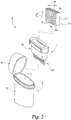
- the cap 40 is attached to the body 20 via a flexible coupling element or hinge 50 that allows the cap 40 to pivot relative to the body 20 between an open position ( FIG. 3 ) and a closed position (not shown).
- the hinge 50 pivotally attaches the cap 40 to the body 20 to provide the primary container 12 with a flip-top configuration wherein the cap 40 is allowed to pivot about a pivot axis P between open and closed positions relative to the body 20.
- the pivot axis P is arranged generally parallel with the minor transverse axis T 2 of the body 20.
- the pivot axis P may be arranged generally parallel with the major transverse axis T 1 of the body 20, or may be arranged at an oblique angle relative to the major and/or minor transverse axes T 1 , T 2 .
- the cap 40 is attached to the body 20 by other suitable attachment techniques, or still other embodiments wherein the cap 40 is separate from the body 20 until fully engaged to the body 20 in the closed position.
- the upper dispensing opening 28 is unobstructed to provide ready access to the test strips 16 contained therein.
- the upper dispensing opening 28 is covered or closed off to isolate the inner chamber 26 from ambient conditions to protect and maintain the test strips 16 within the storage container 10 and/or to prevent moisture or contaminants from entering the storage container 10.
- the cap 40 has an oblong form factor that substantially corresponds to the oblong form factor illustrated and described above with regard to the body 20.
- the cap 40 has an oval shape.
- other shapes are also contemplated including, for example, an elliptical shape or a rectangular shape.
- the cap 40 may be provided with a symmetrical form factor including, for example, a circular cylindrical shape, a square shape, or other suitable shapes or configurations.
- the cap 40 has a first height adjacent a front portion 52 and a lesser second height adjacent a rear portion 54 to thereby provide the cap 40 with a varying cap height.
- the cap 40 is provided with a substantially uniform height.
- the varying height of the cap 40 cooperates with the varying height of the body 20 to provide the primary container 12 with a substantially uniform overall height profile.
- the body 20 and the cap 40 are provided with features that cooperate with one another to provisionally maintain the cap 40 in the closed position to prevent or inhibit inadvertent opening of the cap 40.
- the body 20 and the cap 40 may be provide with detent features, interlocking features, snap features, or fastening features that provisionally maintain the cap 40 in the closed position relative to the body 20. Additionally, variations in the engagement arrangement between cap 40 and the body 20 are also contemplated.
- the cap 40 can be configured to engage the body 20 via a threaded arrangement, a twist lock arrangement, a bayonet lock arrangement, a friction fit arrangement, or other suitable engagement arrangements.
- the cap 40 may be provided with a passage (not shown) extending therethrough and communicating with the inner chamber 26 of the body 20, and with a closing member (not shown) cooperating with the passage such that one or more of the test strips 16 can be removed from the inner chamber 26 without having to disengage the cap 40 from the body 20.
- the closing member may be in the form of a plug, valve, or other suitable closeable access devices.
- the insert component 14 is positioned within the inner chamber 26 in the body 20 of the primary container 12, and is configured to contain and retain a plurality of the biosensor test strips 16 therein. As will be discussed in greater detail below, in one embodiment, the insert component 14 is generally designed to accommodate test strips 16 having varying sizes (e.g., varying test strip lengths and widths).
- various sizes and configurations of the insert component 14 may be provided which are interchangeable with the primary container 12 such that the same primary container 12 may be used to universally/ interchangeably receive various sizes and configurations of the insert component 14, which in turn receives a particular size and configuration of the test strips 16 therein.
- the insert component 14 has a height extending along the longitudinal axis L and generally includes a main body 60 having a lower end portion 60a and an upper end portion 60b, and a spacer portion 120 extending axially from the lower end portion 60a of the main body 60.
- the main body 60 includes an interior region configured to receive and maintain the test strips 16 therein, and the spacer portion 120 rests against the bottom wall 22 of the primary container 12 to position the main body 60 (and the test strips 16 contained therein) at a select height relative to the primary container 12.
- the main body 60 and the spacer portion 120 are formed integral with one another to define a single-piece monolithic structure.
- the main body 60 and the spacer portion 120 comprise separate structures that are couple together via fastening, pinning, fusing, welding, adhering, or other suitable attachment methods to form an integrated insert component 14.
- the insert component 14 need not necessarily include a spacer portion 120.
- the main body 60 has a height extending along the longitudinal axis L, a length extending generally along a first transverse axis T 1 , and a width extending generally along a second transverse axis T 2 .
- the main body 60 further includes a substantially planar bottom wall or base 62 defining an inner support surface 63 and an underside 65a, and a tubular sidewall 64 extending axially from the bottom wall 62 toward the upper end portion 60b and defining a top or upper end surface 65b.
- the bottom wall 62 and the sidewall 64 together define a cylindrical configuration extending generally along the longitudinal axis L and having an interior region 66 defining an upper dispensing opening 68 at the upper end surface 65b.
- the main body 60 may be provided with a number of retainer elements 80 ( FIGS. 7-9 ) including tip portions 82 extending inwardly from an inner surface of the sidewall 64 and laterally into the interior region 66 in the direction of the second transverse axis T 2 , and also extending along the length of the sidewall 64 in the direction of the first transverse axis T 1 , with the tip portions 82 positioned and configured for engagement with the biosensor test strips 16 to aid in retaining the test strips 16 within the interior region 66 of the main body 60.
- the main body 60 may also be provided with a series of low profile divider elements or lateral projections 100 ( FIGS.
- the main body 60 may be further provided with one or more locking ribs or splines 110 ( FIGS.
- the main body 60 of the insert component 14 has an oblong form factor that substantially corresponds to the oblong form factor defined by the body 20 of the primary container 12, including a depth dimension extending along a major axis corresponding to the first transverse axis T 1 from a front portion 72 of the main body 60 to a rear portion 74 of the main body 60, and a width dimension extending along a minor axis corresponding to the second transverse axis T 2 from a first side portion 76 to an opposite second side portion 78.
- the major and minor transverse axes intersect one another at the central longitudinal axis L.
- the main body 60 has a generally oval-shaped cross section.
- the main body 60 may be provided with a symmetrical form factor including, for example, a circular-cylindrical cross section, a square cross section, or other suitable symmetrical cross-sectional shapes and configurations.
- the insert component 14 may be provided with a height profile that generally corresponds to the height profile of the primary container 12 wherein the upper surface 65b of the main body 60 of the insert component 14 is arranged substantially flush with the upper surface 25 of the body 20 of the primary container 12 ( FIG.
- the upper surface 65b of the main body 60 may be recessed below or elevated above the upper surface 25 of the body 20.
- the insert component 14 is provided with a substantially uniform height profile and/or a height profile that does not correspond with the height profile of the body 20 of the primary container 12.
- the main body 60 of the insert component 14 includes a number of retainer elements 80 ( FIGS. 7-9 ) including tip or end portions 82 extending laterally from an inner surface of the sidewall 64 and inwardly into the interior region 66 of the main body 60 in the direction of the second transverse axis T 2 , and also extending along the length of the sidewall 64 in the direction of the first transverse axis T 1 , with the tip portions 82 of the retainer element 80 positioned and configured for frictional engagement with the biosensor test strips 16 to aid in retaining the test strips 16 within the interior region 66 of the main body 60.
- the retainer elements 80 are sized, configured and positioned for frictional engagement with the longitudinal side edges 16c, 16d of the biosensor test strips 16 to aid in retaining/securing the test strips 16 within the interior region 66 of the main body 60 to prevent accidental spillage and/or unintended removal of the test strips 16 from the interior region 66.
- the retainer elements 80 provide relatively unrestricted access to the test strips 16 for retrieval of one or more of the test strips 16 from the storage container 10, and further provide less restrictive insertion of the test strips 16 into the interior region 66 of the insert component 14 to facilitate loading of the test strips 16 into the storage container 10.
- the retainer elements 80 are sized, configured and positioned to provide a lower strip insertion force compared to a higher strip retrieval force, the likes of which will be discussed in greater detail below.
- the insert component 14 is provided with an opposing pair of the retainer elements 80a, 80b ( FIG. 8 ) that are recessed below the upper end surface 65b of the main body 60 and arranged on opposite sides of the interior region 66 for frictional engagement with oppositely facing side edges 16c, 16d of the biosensor test strips 16.
- the insert component 14 is provided with a second opposing pair of the retainer elements that are axially offset from the first opposing pair of retainer elements 80a, 80b in a direction along the longitudinal axis L toward the lower end portion 60a of the main body 60.
- the insert component 14 may be provided with additional opposing pairs of the retainer elements 80a, 80b that are offset from one another in a direction along the vertical longitudinal axis L.
- the retainer elements 80 are mirror images of one another relative to the vertical longitudinal axis L, and that the features and aspects associated with the retainer element 80 apply to both of the retainer elements 80a, 80b.
- the retainer elements 80 each include a mounting portion 84 positioned within corresponding lateral openings 69 formed in the sidewall 64 of the main body 60, with the tip or end portion 82 extending into the interior region 66 of the main body 60 for frictional engagement with a corresponding one of the longitudinal side edges 16c, 16d of the test strips 16.
- the distance separating the tip portions 82 of the retainer elements 80a, 80b and/or the angle at which the retainer elements 80a, 80b extend into the interior region 66 of the main body 60 may be adjusted to accommodate test strips 16 having different strip widths w s (i.e., the nominal width dimension between the longitudinal side edges 16c, 16d).
- Such adjustment of the distance separating the tip portions 82 of the retainer elements 80a, 80b and/or the angular orientation of the retainer elements 80a, 80b may be accomplished by varying the position and/or angular orientation of the retainer elements 80a, 80b relative to the insert component 14, or by removing and replacing the retainer elements 80a, 80b with retainer elements having a different configuration defining a different separation distance and/or angular orientation relative to the insert component 14 to accommodate test strips 16 having different nominal strip widths w s between the longitudinal edges 16c, 16d.
- the retainer elements 80 each include a tip or end portion 82 extending into the interior region 66 of the main body 60 for frictional engagement with the longitudinal side edges 16c, 16d of the test strips 16, and a mounting portion 84 positioned within a corresponding lateral opening 69 formed in the sidewall 64 of the main body 60 of the insert component 14.
- the retainer element 80 may be secured to the main body 60 via fastening, pinning, fusing, welding, adhering, or other suitable attachment techniques.
- the distance separating the tip portions 82 of the retainer elements 80a, 80b and/or the angle at which the retainer elements 80a, 80b extend into the interior region 66 of the main body 60 may be adjusted to accommodate test strips 16 having different nominal strip widths w s .
- the retainer elements 80a, 80b may be designed to be adjustable relative to the insert component 14 (i.e., adjustable position and/or orientation), or designed for disengagement and removal from the insert component 14 for replacement by a different configuration of the retainer elements 80a, 80b to accommodate test strips 16 having different nominal strip widths w s .
- the retainer element 80 includes a tip or end portion 82 and a mounting portion 84, with the tip portion 82 extending laterally from an inner surface of the sidewall 64' and inwardly into the interior region 66' of the main body 60' for engagement with the biosensor test strips 16 (not shown).
- the mounting portion 84 is positioned within a corresponding lateral opening 69' formed in the sidewall 64' of the main body 60' of the insert component 14'.
- the mounting portion 84 includes a lip 86 extending generally along the longitudinal axis L and arranged substantially flush with the inner surface of the sidewall 64'.
- the lip 86 provides additional support and structural integrity to the retainer element 80 and facilities secure engagement with the sidewall 64' of the main body 60'.
- the mounting portion 84 further includes an axial flange 88 positioned along an exterior surface of the sidewall 64' of the main body 60' and extending generally along the longitudinal axis L to provide additional support and structural integrity to the retainer element 80 and to further facilitate secure engagement with the sidewall 64' of the main body 60'.
- the main body 60' of the insert component 14' may be provided with a clip or locking element 61' that is selectively engagable with the axial flange 88 to maintain the retainer element 80 in secure engagement with the insert component 14'.
- the retainer element 80 may be designed to be adjustable relative to the insert component 14 (i.e., adjustable position and/or orientation), or designed for disengagement and removal from the insert component 14 for replacement by a different configuration of the retainer elements 80 to accommodate test strips 16 having different nominal strip widths w s .
- retainer elements 80 Although a specific configuration of the retainer elements 80 has been illustrated and described herein, it should be understood that other configurations of the retainer element 80 and other suitable techniques for attaching the retainer element 80 to the insert container component are also contemplated as falling within the scope of the present invention.
- the tip portion 82 includes an upper surface 90 and a lower surface 92 that are each tapered at an oblique angle relative to the longitudinal axis L. Additionally, in a more specific embodiment, the upper and lower surfaces are each rounded, and the tip portion 82 may further include a rounded distal end surface 94 extending between the upper and lower surfaces 90, 92. The upper and lower surfaces 90, 92 and the end surface 94 cooperate with one another to provide the retainer element 80 with a fin-shaped outer profile.
- the rounded upper surface 90 is provided with a relatively steep taper angle ⁇ 1 (e.g., 50° from the vertical longitudinal axis L) to facilitate relatively unobstructed and less restrictive loading of the test strips 16 into the interior region 66 of the main body 60
- the rounded lower surface 92 is provided with a relatively shallower taper angle ⁇ 2 (e.g., 105° from the vertical longitudinal axis L) to retain/secure the test strips 16 within the interior region 66 of the main body 60 to prevent accidental spillage and/or unintended or involuntary removal of the test strips from the storage container 10.
- the rounded upper surface 90 and the distal end surface 94 each have a convex profile, while the rounded lower surface 92 has a concave profile.
- the tip portion 82 has an overall height measured between the upper and lower surfaces 90, 92 of approximately 0.26 mm, and an overall width measured from the inner surface of the sidewall 64 of the main body 60 to the distal-most end of the retainer element 80 of approximately 0.50 mm.
- shape/configuration of the retainer element 80 and the height/width dimensions are exemplary in nature, and that other shapes, configurations and sizes of the retainer element 80 are also contemplated as falling with the scope of the present invention.
- the test strips 16 may be loaded into the interior region 66 of the main body 60 via a relatively low strip insertion force to enhance or facilitate loading of the test strips 16 into the storage container 10, while the test strips 16 are retained within the interior region 66 of the main body 60 via a relatively higher removal or retrieval force to prevent accidental spillage and/or unintended or involuntary removal of the test strips 16 from the storage container 10.
- the retainer elements 80a, 80b are sized and shaped for resilient deflection during insertion and during removal of the test strips 16 into/from the interior region 66.
- frictional engagement of the tip or end portions 82 of the retainer elements 80a, 80b with the longitudinal side edges 16c, 16d of the test strips 16 aids in maintaining the test strips 16 in a substantially vertical orientation within the storage container 10 so as to maintain the upper end portions of the test strips 16 in a position that allows for easy access and grasping of an individual test strip 16 by the user to facilitate removal of a selected test strip from the storage container 10.
- the retainer elements 80a, 80b also allow relatively free uninhibited movement of the test strips 16 in a first direction D 1 (i.e., in a downward direction along the longitudinal axis L toward the bottom wall 62) to facilitate insertion or loading of the test strips 16 into the storage container 10, while inhibiting or restricting movement of the test strips 16 in an opposite second direction D 2 (i.e., in an upward direction along the longitudinal axis L toward the dispensing opening 68) to retain/secure the test strips 16 within the storage container 10.
- a first direction D 1 i.e., in a downward direction along the longitudinal axis L toward the bottom wall 62
- D 2 i.e., in an upward direction along the longitudinal axis L toward the dispensing opening 68
- retainer elements 80 have been illustrated and described as having a particular shape and configuration, other shapes and configurations are also contemplated.
- FIG. 10 another embodiment of a retainer element 80' is illustrated for use in association with the storage container 10.
- the retainer element 80' may be configured similar to the retainer element 80, including a tip or end portion 82' and a mounting portion 84'.
- the tip portion 82' of the retainer element 80' is provided with a triangular-shaped outer profile including a tapered upper surface upper surface 90' and a tapered lower surface 92'.
- tapered upper and lower surfaces 90', 92' are illustrated as being generally symmetrical to one another and defining substantially equal taper angles, it should be understood that other non-symmetrical embodiments are also contemplated wherein the tapered upper and lower surfaces 90', 92' may be provided with different taper angles.
- FIG. 11 shown therein is another embodiment of a retainer element 80" suitable for use in association with the storage container 10.
- the retainer element 80" may be configured similar to the retainer element 80, including a tip or end portion 82" and a mounting portion 84".
- the tip portion 82" of the retainer element 80" is provided with a oval-shaped or elliptical-shaped outer profile including a tapered upper surface upper surface 90" and a tapered lower surface 92".
- the tapered upper surface 90" and the tapered lower surface 92" are each rounded and define a convex profile.
- other suitable shapes and configurations are also contemplated.
- tapered upper and lower surfaces 90", 92" are illustrated as being generally symmetrical to one another and defining substantially equal taper angles, it should be understood that other non-symmetrical embodiments are also contemplated wherein the tapered upper and lower surfaces 90", 92" may be provided with different taper angles. It should be understood that other embodiments of retainer elements suitable for use in association with the storage container 10 are also contemplated, including retainer elements having end portions that are provided with outer profiles defining other shapes and configurations, including circular configurations, polygonal configurations, curvilinear configurations, or other suitable shapes and configurations.
- the main body 60 of the insert component 14 may be provided with a series of low profile divider elements or lateral projections 100 ( FIGS. 7 and 8 ) extending inwardly from an inner surface of the sidewall 64 and into the interior region 66 of the main body 60 along at least a portion of the overall width dimension w of the interior region 66 (i.e., the interior dimension between inner surfaces of the opposite first and second sides 64a, 64b of the sidewall 64).
- the divider elements 100 are offset from one another along the length dimension l of the interior region 66 (i.e., the interior dimension between opposite end walls 64c, 64d of the sidewall 64) and also extending along a least a portion of the overall height dimension of the interior region 66 (i.e., the interior dimension between the bottom support surface 63 of the bottom wall 62 and the upper surface 65b of the sidewall 64) for engagement with the biosensor test strips 16 to aid in maintaining the test strips 16 in a substantially upright orientation within the interior region 66 of the insert component 14 generally parallel with the longitudinal axis L.
- the low profile divider elements 100 extend across only a portion of the overall width dimension of the interior region 66 of the insert component 14 and do not extend across the entire width dimension w of the interior region 66. In one specific embodiment, the low profile divider elements 100 extend across less than one-half of the width dimension w of the interior region 66, and in a more specific embodiment extend across less than one-quarter of the width dimension w of the interior region 66. However, in other embodiments, the low profile divider elements 100 may extend substantially entirely across the width dimension w of the interior region 66.
- the low profile divider elements 100 extend from the support surface 63 of the bottom wall 62.
- the low profile divider elements 100 may be offset from the support surface 63 of the bottom wall 62 (i.e., the low profile divider elements 100 may be spaced from the support surface 63), and may positioned at various elevations within the interior region 66.
- the low profile divider elements 100 extend along significantly less than the overall height dimension h of the interior region 66.
- the low profile divider elements 100 extend along less than one-half of the height dimension h of the interior region 66, and in a more specific embodiment extend along less than one-quarter of the height dimension h of the interior region 66, and in a still more specific embodiment extend along less than one-eighth of the height dimension h of the interior region 66.
- the low profile divider elements 100 may extend substantially entirely along the entire height dimension h of the interior region 66.
- the low profile divider elements 100 are provided with varying heights.
- the insert component 14 is provided with a number of high profile divider elements 102 extending inwardly from an inner surface of the sidewall 64 and into the interior region 66, and having a height that is greater than the height of low profile divider elements 100.
- the high profile divider elements 102 are positioned in the central section of the interior region 66.
- other positions of the high profile divider elements 102 are also contemplated.
- the high profile divider elements 102 extends along greater than one-half of the height dimension h of the interior region 66.
- other heights of the high profile divider elements 102 are also contemplated.
- a first set 100a of the low profile divider elements 100 extends laterally from a first sidewall 64a and into the interior region 66
- a second set 100b of the low profile divider elements 100 extends laterally from an opposite second sidewall 64b and into the interior region 66.
- the low profile divider elements 100 may extend from only one of the first and second sidewalls 64a, 64b.
- the low profile divider elements 100 may extend from the support surface 63 of the bottom wall 62, but do not contact or extend from either of the first and second sidewalls 64a, 64b.
- the first set 100a of the low profile divider elements are aligned in an opposing manner with the second set 100b of the low profile divider elements.
- the first set 100a of the low profile divider elements may be offset from the second set 100b of the low profile divider elements (i.e., the first set 100a of the low profile divider elements may be aligned with the spaces or gaps between the second set 100b of the low profile divider elements).
- the biosensor test strips 16 are positioned within the interior region 66 of the insert component 14 and are maintained in a substantially vertical orientation via the low profile divider elements 100 and/or the high profile divider elements 102 to prevent the test strips 16 from falling lengthwise into the interior region 66 as the number of test strips 16 contained within the interior region 66 is gradually decreased, yet the divider elements 100, 102 do not impede removal of individual strips from the interior region 66 by the user.
- the divider elements 100, 102 extend across less than the entire width dimension of the interior region 66 and along less than the entire height dimension, the divider elements 100, 102 do not hinder or otherwise obstruct (either physically or visually) removal of the biosensor test strips 16 from the interior region 66.
- the divider elements 100, 102 act as stabilizers to maintain the test strips 16 in a substantially vertical or upright orientation and in a neat and compact arrangement within the insert component 14 for presentation to the user, while still allowing for easy access and removal of an individual test strip 16 from the insert component 14. Additionally, in order to facilitate loading of the test strips 16 into the interior region 66 of the insert component 14, the upper surfaces of the low profile divider elements 100 and/or the high profile divider elements 102 may be angled or tapered.
- the main body 60 of the insert component 14 may be provided with one or more raised locking ribs or splines 110 ( FIGS. 4-6 ) extending outwardly from an outer surface of the sidewall 64 in the direction of the second transverse axis T 2 and also extending along the height of the sidewall 64 in the direction of the longitudinal axis L for engagement with an inner surface of the body 20 of the primary container 12 to aid in maintaining the insert component 14 within the inner chamber 26 of the primary container 12.
- the locking ribs 110 extend along less than the overall height profile of the main body 60, but may alternatively extend substantially entirely along the overall height profile of the main body 60.
- the locking ribs 110 are preferably located along an upper portion of the main body 60 to facilitate stability of the insert component 14 within the primary container 12, as well as to stabilize and/or strengthen the tubular sidewall 24 of the primary container 12 against inward deflection.
- the locking ribs 110 are preferably positioned below the seal region between the body 20 and the cap 40 of the primary container 12 to avoid interference with and/or distortion of the seal which might otherwise compromise the integrity of the seal.
- the main body 60 includes a pair of locking ribs 110a, 110b extending outwardly from each of the opposite sidewalls of the insert component 14 and positioned adjacent the front and rear portions 32, 34.
- the main body 60 may be provided with any number of the locking ribs 110 positioned along other portions of the main body 60.
- the locking ribs 110 may be provided with a roughened or pointed tip portion 112 to facilitate secure locking engagement with the inner surface of the primary container 12 to securely maintain the insert component 14 within the inner chamber 26 of the primary container 12.
- the insert component 14 may be provided with a spacer portion 120 ( FIGS. 4-6 ) extending axially from the lower end portion 60a of the main body 60 and which abuts against the bottom wall 22 of the primary container 12 (or other portions of the primary container 12) to position the main body 60 (and the test strips 16 contained therein) at a select height relative to the primary container 12.
- the spacer portion 120 comprises a flange or strut extending axially from the underside surface 65a defined by the bottom wall 62 of the main body 60.
- the strut 120 has a substantially rectangular configuration and projects axially from the underside 65a of the bottom wall 62 generally along the longitudinal axis L, and defines a strut height h s measured along the longitudinal axis L from the underside 65a of the bottom wall 62 to the distal end surface 122 of the strut 120.
- the distal end surface 122 of the strut 120 abuts/rests against an inner surface of the bottom wall 22 of the primary container 12 to thereby position the main body 60 of the insert component 14 (and the test strips 16 contained therein) at a select height relative to the primary container 12.
- the insert component 14 is preferably positioned within the primary container 12 at a select height where at least the upper end edges 16a of the test strips 16 are located above the upper surface 25 of the body 20 of the primary container 12 to allow for easy access and grasping of an individual test strip 16 by the user, but with the upper end edges 16a of the test strips 16 positioned below the upper wall 42 of the cap 40 when the cap 40 is in a closed position to prevent bending or damaging of the test strips 16.
- the strut 120 has been illustrated and described as having a substantially rectangular configuration, it should be understood that outer shapes and configurations of the strut 120 are also contemplated.
- the strut 120 includes a series of break-off or removable tabs or strips 124 that are separated/spaced from one another along the longitudinal axis L by interface regions 126 configured to allow for the selective removal of one or more of the removable tabs 124 from the strut 120.
- the interface regions 126 comprise frangible regions or regions of reduced strength that separate adjacent pairs of the removable tabs 124.
- the frangible regions 126 define a series of pre-defined fracture initiator zones configured to facilitate initiation of a fracture or break along a select one of the frangible regions 126 upon application of a sufficient torsional or bending force onto the select frangible region so as to allow for removal of a select length of the strut 120 distal of the fracture zone via removal of one or more of the removable tabs 124.
- the distal-most tab 124 may be provided with a notch or recessed region 128 extending along a portion of the length of the strut 120.
- the regions of reduced strength defined by the frangible regions 126 are each formed by a localized reduced thickness of the strut 120.
- the localized reduced thickness of the frangible regions 126 are provided by grooves or scores extending laterally along opposite sides of the strut 120 in a direction transverse to the longitudinal axis L.
- the grooves 126 may be defined along a single side of the strut 120.
- the grooves 126 are illustrated as extending along the entire length dimension of the strut 120, it should be understood that in other embodiments, the grooves 126 may extend along only a portion of the length dimension of the strut 120, or may be intermittently dispersed along the length dimension of the strut 120.
- the frangible regions 126 can take on configurations other than grooves, including other structural features that provided a weakened region intermediate adjacent pairs of the removable tabs 124.
- the frangible regions 126 may comprise localized reductions in the material thickness of the wall of the strut 120 between adjacent pairs of the removable tabs 124, or localized regions of reduced strength intermediate adjacent pairs of the removable tabs 124.
- the interface regions 126 may take on configurations other than the frangible regions.
- the interface regions 126 may be configured to allow for the selective removal of one or more of the removable tabs 124 from the strut 120 other than by breaking or fracturing.
- one or more of the removable tabs 124 can be removed or broken off at a select one of the frangible regions 126 and removed to thereby change the strut height h s of the strut 120, which in turn positions the insert component 14 at a lower recessed position within the primary container 12 to accommodate test strips 16 having a greater strip length l s wherein at least the upper edges 16a of the test strips 16 are located above the upper surface 25 of the body 20 of the primary container 12 to allow for easy access and grasping of an individual test strip 16 by the user.
- the strut height h s can be selectively and easily adjusted via removal of one or more of the removable tabs 124 to accommodate a wide variety of test strip length l s while presenting at least the end edges 16a of the test strips 16 at a generally uniform height within the storage container 10 (i.e., at a select distance above the upper surface 25 of the body 20 of the primary container 12) without having to change or reconfigure the primary container 12.
- providing the insert component 14 with a strut 120 having an adjustable strut height h s provides the storage container 10 with the ability to be used in association with a wide variety of test strip length l s .
- the removable tabs 124 and/or the frangible regions 126 may be configured for releasable engagement with a force application instrument (not shown) to initiate breaking, fracturing or removal of one or more of the strut 120 along a select one of the frangible regions 126.
- a force application instrument not shown
- one or more of the removable tabs 124 may be broken off of or otherwise removed from the strut 120 via direct application of a manual force.
- the strut 120 includes three of the removable tabs 124. However, it should be understood that the strut 120 may be provided with any number of the removable tabs 124, including one, two, or four or more of the removable tabs 124.
- FIG. 12 shown therein is another form of a storage container 200 for containing and retaining a plurality of vertically oriented articles therein.
- the storage container 200 extends along a central longitudinal axis L and generally includes a primary container 212 and an insert component 214 positioned within an interior region of the primary container 212 and configured to contain and retain a plurality of vertically oriented articles such as, for example, the biosensor test strips 16 illustrated and described above.
- the primary container 212 generally includes a body 220 having a substantially planar bottom wall or base 222, and a tubular sidewall 224 extending axially from the bottom wall 222.
- the bottom wall 222 and the sidewall 224 together define a cylindrical configuration defining an inner chamber 226 extending generally along a longitudinal axis L.
- the primary container 212 may include a cap (not shown) removably engagable with the body 220 to close off the storage container 200 to prevent moisture and/or containments from entering the interior region of the storage container 200.
- the body 220 has an oblong form factor defining a generally oval or elliptical-shaped outer cross sectional profile. However, other shapes and cross sections are also contemplated.
- the insert component 214 is positioned within the inner chamber 226 of the body 220 of the primary container 212, and is configured to contain and retain a plurality of the biosensor test strips 16 therein.
- the insert component 214 generally includes a main body 260 having a substantially planar bottom wall or base 262 and a tubular sidewall 264 extending axially from the bottom wall 262.
- the bottom wall 262 and the sidewall 264 together define a cylindrical configuration defining an interior region 266 extending generally along the longitudinal axis L and sized and configured to receive and maintain the biosensor test elements 16 therein.
- the main body 260 is provided with a pair of retainer elements 280a, 280b positioned on opposite sides of the tubular sidewall 264 relative to the longitudinal axis L.
- the retainer elements 280a, 280b in turn define a first pair of retainer tip portion 282a extending laterally into the interior region 266, and a second pair of retainer tip portions 282b extending laterally into the interior region 266 and axially offset from the first pair of retainer tip portions 282a.
- the first pair of retainer tip portions 282a are positioned adjacent an upper end surface of the sidewall 264 and are arranged in general opposition with one another on opposite sides of the longitudinal axis L
- the second pair of retainer tip portions 282b are positioned adjacent the bottom wall 262 and are arranged in general opposition with one another on opposite sides of the longitudinal axis L.
- the pair of retainer elements 280a, 280b further include a mounting portion or axial flange 284 configured to interconnect the upper and lower retainer tip portions 282a, 282b with one another. Additionally, the retainer elements 280a, 280b are positioned within corresponding lateral openings 269 extending through opposite sides of the tubular sidewall 264 such that the first and second pairs of retainer tip portions 282a, 282b extend inwardly from inner surfaces of the sidewall 264 and into the interior region 266.
- the upper and lower retainer tip portions 282a, 282b defined by the retainer elements 280a, 280b extend into the interior region 266 of the insert 214 at an oblique angle relative to the longitudinal axis L.
- the upper and lower retainer tip portions 282a, 282b extend into the interior region 266 at approximately a 135° taper angle relative to the longitudinal axis L.
- other oblique angles are also contemplated.
- test strips 16 may be loaded into the interior region 266 of the main body 260 via a relatively low strip insertion force to enhance or facilitate loading of the test strips into the storage container 200, while the test strips 16 are retained within the interior region 266 of the main body 260 via a relatively higher removal or retrieval force to prevent accidental spillage and/or unintended or involuntary removal of the test strips 16 from the storage container 200.
- the retainer tip portions 282a, 282b are sized and shaped for resilient deflection during insertion and during removal of the test strips into/out of the interior region 266.
- frictional engagement of the retainer tip portions 282a, 282b with the longitudinal side edges 16c, 16d of the test strips 16 aids in maintaining the test strips 16 in a substantially vertical orientation within the storage container 200 so as to maintain the upper end portions of the test strips in a position that allows for easy access and grasping of an individual test strip by the user to facilitate removal of a selected test strip from the storage container 200.
- the storage container 300 for containing and retaining a plurality of vertically oriented articles therein.
- the storage container 300 generally includes a primary container 312 and an insert component 314 positioned within an interior region of the primary container 312 and configured to contain and retain a plurality of vertically oriented articles such as, for example, the biosensor test strips 16 illustrated and described above.
- the primary container 312 generally includes a body 320 having a substantially planar bottom wall or base 322, and a tubular sidewall 324 extending axially from the bottom wall 322.
- the bottom wall 322 and the sidewall 324 together define a cylindrical configuration defining an inner chamber 326 extending generally along the longitudinal axis L.
- the primary container 312 may include a cap (not shown) removably engagable with the body 320 to close off the storage container 300 to prevent moisture and/or containments from entering the interior region of the storage container 300.
- the body 320 has an oblong form factor defining a generally oval or elliptical-shaped outer cross sectional profile. However, other shapes and cross sections are also contemplated.
- the insert component 314 is positioned within the inner chamber 326 of the body 320 of the primary container 312, and is configured to contain and retain a plurality of the biosensor test strips 16 therein.
- the insert component 314 generally includes a main body 360 having a substantially planar bottom wall or base 362 and a tubular sidewall 364 extending axially from the bottom wall 362.
- the bottom wall 362 and the sidewall 364 together define a cylindrical configuration defining an interior region 366 extending generally along the longitudinal axis L and sized and configured to receive and maintain the biosensor test elements 16 therein.
- the main body 360 is provided with a first pair of retainer elements 380a, 380b positioned on opposite sides of the tubular sidewall 364 adjacent an upper end of the sidewall 364, and a second pair of retainer elements 380c, 380d positioned on opposite sides of the tubular sidewall 364 adjacent the bottom wall 362.
- the retainer elements 380a-380d in turn define a first pair of retainer tip portion 382a extending laterally into the interior region 366, and a second pair of retainer tip portions 382b extending laterally into the interior region 366 and axially offset from the first pair of retainer tip portions 382a.
- the first pair of the retainer tip portions 382a are positioned adjacent an upper end surface of the sidewall 364 and are arranged in general opposition with one another on opposite sides of the longitudinal axis L
- the second pair of retainer tip portions 382b are positioned adjacent the bottom wall 362 and are arranged in general opposition with one another on opposite sides of the longitudinal axis L.
- Each of the retainer elements 380a-380d further includes a mounting portion 384 configured to mount the retainer tip portions 382a, 382b to the tubular sidewall 364.
- the upper and lower pairs of the retainer tip portions 382a, 382b extend into the interior region 366 of the insert 314 and include upper and lower surfaces that are each arranged at an oblique angle relative to the longitudinal axis L.
- the upper surface has a convex configuration and the lower surface has a concave configuration, with the upper and lower surfaces intersecting at a relatively pointed distal end.
- other shapes and configurations of the upper and lower surfaces are also contemplated.
- test strips 16 may be loaded into the interior region 366 of the main body 360 via a relatively low strip insertion force to enhance or facilitate loading of the test strips 16 into the storage container 300, while the test strips 16 are retained within the interior region 366 of the main body 360 via a relatively higher removal or retrieval force to prevent accidental spillage and/or unintended or involuntary removal of the test strips 16 from the storage container 300.
- the retainer tip portions 382a, 382b are sized and shaped for resilient deflection during insertion and during removal of the test strips 16 into/out of the interior region 366.
- frictional engagement of the retainer tip portions 382a, 382b with the longitudinal side edges 16c, 16d of the test strips 16 aids in maintaining the test strips 16 in a substantially vertical orientation within the storage container 300 so as to maintain the upper end portions of the test strips 16 in a position that allows for easy access and grasping of an individual test strip by the user to facilitate removal of a selected test strip from the storage container 300.
- the main body 360 of the insert component 314 is provided with a series of low profile divider elements or lateral projections 390a, 390b extending inwardly from an inner surface of the sidewall 364 and into the interior region 366.
- the divider elements 390a, 390b are offset from one another along the length dimension of the interior region 366 and also extend along a least a portion of the overall height dimension of the interior region 366.
- the divider elements 390a, 390b are configured for engagement with the biosensor test strips 16 to aid in maintaining the test strips 16 in a substantially upright orientation within the interior region 366 of the insert component 314 generally parallel with the longitudinal axis L.
- respective pairs of the divider elements 390a, 390b are arranged in opposition to one another across the interior region 366 relative to the longitudinal axis L.
Landscapes
- Health & Medical Sciences (AREA)
- Chemical & Material Sciences (AREA)
- Engineering & Computer Science (AREA)
- Life Sciences & Earth Sciences (AREA)
- Biomedical Technology (AREA)
- Physics & Mathematics (AREA)
- Clinical Laboratory Science (AREA)
- Chemical Kinetics & Catalysis (AREA)
- Analytical Chemistry (AREA)
- General Health & Medical Sciences (AREA)
- Hematology (AREA)
- Biophysics (AREA)
- General Physics & Mathematics (AREA)
- Molecular Biology (AREA)
- Urology & Nephrology (AREA)
- Food Science & Technology (AREA)
- Medicinal Chemistry (AREA)
- Biochemistry (AREA)
- Optics & Photonics (AREA)
- Immunology (AREA)
- Pathology (AREA)
- Investigating Or Analysing Biological Materials (AREA)
- Sampling And Sample Adjustment (AREA)
- Packages (AREA)
- Details Of Rigid Or Semi-Rigid Containers (AREA)
Applications Claiming Priority (3)
| Application Number | Priority Date | Filing Date | Title |
|---|---|---|---|
| US13/305,005 US9914126B2 (en) | 2011-11-28 | 2011-11-28 | Storage container for biosensor test elements |
| EP12790797.0A EP2786138B1 (fr) | 2011-11-28 | 2012-11-23 | Insert pour un récipient de stockage des éléments d'essai de biocapteur |
| PCT/EP2012/004846 WO2013079177A1 (fr) | 2011-11-28 | 2012-11-23 | Élément inséré pour récipient de stockage pour éléments d'essai de biocapteur |
Related Parent Applications (2)
| Application Number | Title | Priority Date | Filing Date |
|---|---|---|---|
| EP12790797.0A Division-Into EP2786138B1 (fr) | 2011-11-28 | 2012-11-23 | Insert pour un récipient de stockage des éléments d'essai de biocapteur |
| EP12790797.0A Division EP2786138B1 (fr) | 2011-11-28 | 2012-11-23 | Insert pour un récipient de stockage des éléments d'essai de biocapteur |
Publications (2)
| Publication Number | Publication Date |
|---|---|
| EP3575790A2 true EP3575790A2 (fr) | 2019-12-04 |
| EP3575790A3 EP3575790A3 (fr) | 2020-02-26 |
Family
ID=47222010
Family Applications (2)
| Application Number | Title | Priority Date | Filing Date |
|---|---|---|---|
| EP12790797.0A Active EP2786138B1 (fr) | 2011-11-28 | 2012-11-23 | Insert pour un récipient de stockage des éléments d'essai de biocapteur |
| EP19187634.1A Pending EP3575790A3 (fr) | 2011-11-28 | 2012-11-23 | Insert pour un récipient de stockage des éléments d'essai de biocapteur |
Family Applications Before (1)
| Application Number | Title | Priority Date | Filing Date |
|---|---|---|---|
| EP12790797.0A Active EP2786138B1 (fr) | 2011-11-28 | 2012-11-23 | Insert pour un récipient de stockage des éléments d'essai de biocapteur |
Country Status (5)
| Country | Link |
|---|---|
| US (2) | US9914126B2 (fr) |
| EP (2) | EP2786138B1 (fr) |
| ES (1) | ES2752450T3 (fr) |
| PL (1) | PL2786138T3 (fr) |
| WO (1) | WO2013079177A1 (fr) |
Families Citing this family (7)
| Publication number | Priority date | Publication date | Assignee | Title |
|---|---|---|---|---|
| US9914126B2 (en) * | 2011-11-28 | 2018-03-13 | Roche Diabetes Care, Inc. | Storage container for biosensor test elements |
| AU356004S (en) * | 2013-11-18 | 2014-06-18 | Novartis Ag | Container |
| CN110068674B (zh) * | 2014-06-05 | 2020-09-08 | 豪夫迈·罗氏有限公司 | 可交换的测试元件保持器 |
| JP6863977B2 (ja) * | 2015-12-08 | 2021-04-21 | エフ.ホフマン−ラ ロシュ アーゲーF. Hoffmann−La Roche Aktiengesellschaft | テスト素子保持用仕切り |
| CN106697512A (zh) * | 2017-01-23 | 2017-05-24 | 苏州诺纳可电子科技有限公司 | 一种铁片发包夹 |
| CN107878900A (zh) * | 2017-11-07 | 2018-04-06 | 郭旭红 | 一种适合肾内科用多功能药剂分类装置 |
| DE212018000362U1 (de) * | 2017-11-28 | 2020-06-30 | Koki Holdings Co., Ltd. | Zentrifugenprobenbehälter, Zentrifugenrotor, der diesen verwendet, und Zentrifuge |
Citations (14)
| Publication number | Priority date | Publication date | Assignee | Title |
|---|---|---|---|---|
| US4999482A (en) | 1988-05-24 | 1991-03-12 | Goldstar Co, Ltd. | Optical scanning system for a bar code reader |
| US5352351A (en) | 1993-06-08 | 1994-10-04 | Boehringer Mannheim Corporation | Biosensing meter with fail/safe procedures to prevent erroneous indications |
| US5424035A (en) | 1993-03-31 | 1995-06-13 | Boehringer Mannheim Gmbh | Test strip analysis system |
| US5438271A (en) | 1993-06-08 | 1995-08-01 | Boehringer Mannheim Corporation | Biosensing meter which detects proper electrode engagement and distinguishes sample and check strips |
| US5463467A (en) | 1993-06-29 | 1995-10-31 | Boehringer Mannheim Gmbh | Light source pulsed with irregular pulse sequence in analog photometric signal evaluation for a test carrier analysis system |
| US5889585A (en) | 1996-09-24 | 1999-03-30 | Lre Technology Partner Gmbh | Method and apparatus for the measurement of blood sugar |
| USRE36268E (en) | 1988-03-15 | 1999-08-17 | Boehringer Mannheim Corporation | Method and apparatus for amperometric diagnostic analysis |
| US5997817A (en) | 1997-12-05 | 1999-12-07 | Roche Diagnostics Corporation | Electrochemical biosensor test strip |
| US6055060A (en) | 1996-07-16 | 2000-04-25 | Boehringer Mannheim Gmbh | Analytical system with means for detecting too small sample volumes |
| US6645368B1 (en) | 1997-12-22 | 2003-11-11 | Roche Diagnostics Corporation | Meter and method of using the meter for determining the concentration of a component of a fluid |
| US6662439B1 (en) | 1999-10-04 | 2003-12-16 | Roche Diagnostics Corporation | Laser defined features for patterned laminates and electrodes |
| US20050016844A1 (en) | 2003-06-20 | 2005-01-27 | Burke David W. | Reagent stripe for test strip |
| US6906802B2 (en) | 2000-12-08 | 2005-06-14 | Roche Diagnostic Operations, Inc. | System for analyzing sample liquids containing a position control unit |
| US7008799B1 (en) | 1997-12-04 | 2006-03-07 | Roche Diagnostics Gmbh | Analytical test element with a capillary channel |
Family Cites Families (50)
| Publication number | Priority date | Publication date | Assignee | Title |
|---|---|---|---|---|
| US375412A (en) * | 1887-12-27 | Allen p | ||
| US1450674A (en) * | 1921-11-18 | 1923-04-03 | Howard F Marston | Size-reducible box |
| US1827396A (en) * | 1929-04-22 | 1931-10-13 | American Tobacco Co | Telescopically collapsible box |
| US2487107A (en) * | 1947-02-11 | 1949-11-08 | Andrea Charles J D | Receptacle for cotton rolls |
| US2727547A (en) * | 1953-08-21 | 1955-12-20 | American Optical Corp | Containers |
| US3096960A (en) * | 1961-07-03 | 1963-07-09 | Thurlow R Kinney | Implement holder |
| US3918920A (en) * | 1974-01-07 | 1975-11-11 | Beckman Instruments Inc | Holder for sample containers of different sizes |
| US4911344A (en) | 1988-03-23 | 1990-03-27 | Tek-Aids Inc. | Strip dispenser box |
| US5080232A (en) * | 1989-06-01 | 1992-01-14 | Nalge Company | Test tube rack and retainer |
| US5316146A (en) * | 1991-03-06 | 1994-05-31 | Ulster Scientific, Inc. | Vial transporter |
| US5275367A (en) * | 1992-02-14 | 1994-01-04 | Frye Bruce J | Self securing holding device and method |
| DE4328815A1 (de) * | 1993-08-27 | 1995-03-02 | Boehringer Mannheim Gmbh | System zur Bevorratung von Testelementen |
| DE19546684A1 (de) | 1995-12-14 | 1997-06-19 | Boehringer Mannheim Gmbh | Vorratsbehältnis für streifenförmige Testelemente |
| DE19730696B4 (de) * | 1997-07-17 | 2011-06-01 | Rösler, Peter | Vorrichtung zur Aufnahme von langgestreckten Gegenständen |
| US7063234B2 (en) | 2000-12-29 | 2006-06-20 | Csp Technologies, Inc. | Meter strip dispenser assembly |
| US6502711B1 (en) * | 2001-04-20 | 2003-01-07 | Kerry J. C. Mc Rae | Container holding apparatus |
| US6908008B2 (en) | 2001-12-21 | 2005-06-21 | Lifescan, Inc. | Test device with means for storing and dispensing diagnostic strips |
| US6872358B2 (en) | 2002-01-16 | 2005-03-29 | Lifescan, Inc. | Test strip dispenser |
| GB2390602A (en) | 2002-04-02 | 2004-01-14 | Inverness Medical Ltd | Test strip dispenser vial and cassette |
| US7172728B2 (en) | 2002-04-02 | 2007-02-06 | Lifescan, Inc. | Test strip containers and methods of using the same |
| WO2004000680A1 (fr) | 2002-06-25 | 2003-12-31 | Capitol Plastic Products Llc | Recipient non cylindrique ouvrable et resistant a l'humidite pour biens de consommation courante |
| US7628292B2 (en) | 2003-03-03 | 2009-12-08 | Airsec S.A. | Device for dispensing oblong objects, comprising one main opening and at least one other elongated opening |
| US7118522B2 (en) * | 2003-04-15 | 2006-10-10 | Beckman Coulter, Inc. | Centrifuge adapter |
| US7516845B2 (en) * | 2004-03-31 | 2009-04-14 | Inverness Medical Limited | Medical device package with deformable projections |
| US7582262B2 (en) | 2004-06-18 | 2009-09-01 | Roche Diagnostics Operations, Inc. | Dispenser for flattened articles |
| DE602006014717D1 (de) | 2005-03-22 | 2010-07-15 | Bayer Healthcare Llc | Kartusche mit rad zum öffnungsverschluss |
| US20070080093A1 (en) * | 2005-10-11 | 2007-04-12 | Agamatrix, Inc. | Vial for test strips |
| US7501093B2 (en) | 2005-10-18 | 2009-03-10 | Agamatrix, Inc. | Vial for test strips |
| US7484620B2 (en) * | 2005-11-14 | 2009-02-03 | Black & Decker Inc. | Accessory storage case |
| WO2008092470A1 (fr) | 2007-01-29 | 2008-08-07 | Egomedical Swiss Ag | Récipient rescellable pour stocker des éléments de test sensibles à l'humidité |
| EP2031389B1 (fr) | 2007-09-03 | 2012-01-25 | Airsec S.A.S. | Contenant pour bandes de test |
| USD599322S1 (en) | 2007-12-27 | 2009-09-01 | Sony Corporation | Optical disc player with radio receiver |
| US20110127269A1 (en) | 2008-05-15 | 2011-06-02 | Michael Bucholtz | Vial with non-round seal |
| USD599032S1 (en) | 2008-05-16 | 2009-08-25 | Csp Technologies, Inc. | Vial |
| US20100000905A1 (en) * | 2008-07-03 | 2010-01-07 | Abbott Diabetes Care, Inc. | Strip vial and cap |
| WO2010065309A1 (fr) * | 2008-12-02 | 2010-06-10 | Bayer Healthcare Llc | Systèmes de contenants pour détecteurs d’analytes munis d’un élévateur de détecteur et procédés de stockage |
| US8236254B2 (en) * | 2009-05-14 | 2012-08-07 | Abbott Diabetes Care Inc. | Cap-linked test strip carrier for vial augmentation |
| US8622231B2 (en) * | 2009-09-09 | 2014-01-07 | Roche Diagnostics Operations, Inc. | Storage containers for test elements |
| US20110127175A1 (en) | 2009-11-30 | 2011-06-02 | Roche Diagnostics Operations, Inc. | Test strip container with expandable insert and methods of manufacturing and utilization thereof |
| US8844725B2 (en) * | 2010-01-20 | 2014-09-30 | Roche Diagnostics Operations, Inc. | Test strip container with strip retainer and methods of manufacturing and utilization thereof |
| US8394343B2 (en) * | 2010-04-27 | 2013-03-12 | Roche Diagnostics Operations, Inc. | Integrated test strip container with retaining insert |
| US8757386B2 (en) * | 2010-09-30 | 2014-06-24 | Abbott Diabetes Care Inc. | Analyte test strip containers and inserts |
| PE20141796A1 (es) * | 2011-06-14 | 2014-12-12 | Ax Lab Innovation Aps | Conjunto contenedor y metodo asociado |
| US9745101B2 (en) * | 2011-11-09 | 2017-08-29 | Csp Technologies, Inc. | Container with insert |
| US9914126B2 (en) * | 2011-11-28 | 2018-03-13 | Roche Diabetes Care, Inc. | Storage container for biosensor test elements |
| WO2014134455A1 (fr) * | 2013-03-01 | 2014-09-04 | Csp Technologies, Inc. | Contenant pourvu d'éléments insérables |
| CN110068674B (zh) * | 2014-06-05 | 2020-09-08 | 豪夫迈·罗氏有限公司 | 可交换的测试元件保持器 |
| US20160031627A1 (en) * | 2014-08-04 | 2016-02-04 | Huan-Fu Yeh | Moisture Proof Container |
| CN205257032U (zh) * | 2015-12-10 | 2016-05-25 | 三诺生物传感股份有限公司 | 一种试条盒 |
| CN205257033U (zh) * | 2015-12-10 | 2016-05-25 | 三诺生物传感股份有限公司 | 一种试条盒 |
-
2011
- 2011-11-28 US US13/305,005 patent/US9914126B2/en active Active
-
2012
- 2012-11-23 ES ES12790797T patent/ES2752450T3/es active Active
- 2012-11-23 EP EP12790797.0A patent/EP2786138B1/fr active Active
- 2012-11-23 EP EP19187634.1A patent/EP3575790A3/fr active Pending
- 2012-11-23 WO PCT/EP2012/004846 patent/WO2013079177A1/fr unknown
- 2012-11-23 PL PL12790797T patent/PL2786138T3/pl unknown
-
2018
- 2018-02-02 US US15/887,221 patent/US10071380B2/en active Active
Patent Citations (14)
| Publication number | Priority date | Publication date | Assignee | Title |
|---|---|---|---|---|
| USRE36268E (en) | 1988-03-15 | 1999-08-17 | Boehringer Mannheim Corporation | Method and apparatus for amperometric diagnostic analysis |
| US4999482A (en) | 1988-05-24 | 1991-03-12 | Goldstar Co, Ltd. | Optical scanning system for a bar code reader |
| US5424035A (en) | 1993-03-31 | 1995-06-13 | Boehringer Mannheim Gmbh | Test strip analysis system |
| US5438271A (en) | 1993-06-08 | 1995-08-01 | Boehringer Mannheim Corporation | Biosensing meter which detects proper electrode engagement and distinguishes sample and check strips |
| US5352351A (en) | 1993-06-08 | 1994-10-04 | Boehringer Mannheim Corporation | Biosensing meter with fail/safe procedures to prevent erroneous indications |
| US5463467A (en) | 1993-06-29 | 1995-10-31 | Boehringer Mannheim Gmbh | Light source pulsed with irregular pulse sequence in analog photometric signal evaluation for a test carrier analysis system |
| US6055060A (en) | 1996-07-16 | 2000-04-25 | Boehringer Mannheim Gmbh | Analytical system with means for detecting too small sample volumes |
| US5889585A (en) | 1996-09-24 | 1999-03-30 | Lre Technology Partner Gmbh | Method and apparatus for the measurement of blood sugar |
| US7008799B1 (en) | 1997-12-04 | 2006-03-07 | Roche Diagnostics Gmbh | Analytical test element with a capillary channel |
| US5997817A (en) | 1997-12-05 | 1999-12-07 | Roche Diagnostics Corporation | Electrochemical biosensor test strip |
| US6645368B1 (en) | 1997-12-22 | 2003-11-11 | Roche Diagnostics Corporation | Meter and method of using the meter for determining the concentration of a component of a fluid |
| US6662439B1 (en) | 1999-10-04 | 2003-12-16 | Roche Diagnostics Corporation | Laser defined features for patterned laminates and electrodes |
| US6906802B2 (en) | 2000-12-08 | 2005-06-14 | Roche Diagnostic Operations, Inc. | System for analyzing sample liquids containing a position control unit |
| US20050016844A1 (en) | 2003-06-20 | 2005-01-27 | Burke David W. | Reagent stripe for test strip |
Also Published As
| Publication number | Publication date |
|---|---|
| EP2786138B1 (fr) | 2019-09-04 |
| WO2013079177A1 (fr) | 2013-06-06 |
| US20130134159A1 (en) | 2013-05-30 |
| US20180154365A1 (en) | 2018-06-07 |
| PL2786138T3 (pl) | 2020-02-28 |
| US9914126B2 (en) | 2018-03-13 |
| ES2752450T3 (es) | 2020-04-06 |
| US10071380B2 (en) | 2018-09-11 |
| EP2786138A1 (fr) | 2014-10-08 |
| EP3575790A3 (fr) | 2020-02-26 |
Similar Documents
| Publication | Publication Date | Title |
|---|---|---|
| US10071380B2 (en) | Storage container for biosensor test elements | |
| American Diabetes Association | 7. Diabetes technology: standards of medical care in diabetes—2019 | |
| EP2475596B1 (fr) | Contenants de stockage pour éléments de test | |
| EP3106871B1 (fr) | Procédé de vérification de la précision du fonctionnement d'un dispositif de surveillance d'analyte | |
| US20190282768A1 (en) | Pen needle assembly | |
| DK2919741T3 (en) | Capsule for a container for enteral nutrition | |
| WO2007096832A1 (fr) | Contenant pour stockage de bâtonnets diagnostiques usagés | |
| CA2218248A1 (fr) | Support de flacon | |
| JP3896152B2 (ja) | 採血具の逆流防止構造、ルアー針、採血針及び採血ホルダー | |
| CA2852075C (fr) | Ensemble de prelevement sanguin | |
| US8919607B2 (en) | Analyte test strip vial | |
| EP2370328B1 (fr) | Récipient de type tambour pour À©léments analytiques | |
| CN111032126B (zh) | 用于具有较少防腐剂的药物的多次使用药物递送装置 | |
| EP3836838B1 (fr) | Système de collecte de fluide biologique et ensemble de stabilisation | |
| US20100047918A1 (en) | Test-sensor cartridge | |
| US20110040316A1 (en) | Method and Apparatus for a Single Handed Squeeze Lancet | |
| JP7129050B2 (ja) | 針廃棄用容器 | |
| WO2018230607A1 (fr) | Contenant de mise au rebut d'aiguille | |
| CN117597195A (zh) | 用于毛细血管采血的样本容器 | |
| CN117794457A (zh) | 毛细血管血液采集装置 |
Legal Events
| Date | Code | Title | Description |
|---|---|---|---|
| PUAI | Public reference made under article 153(3) epc to a published international application that has entered the european phase |
Free format text: ORIGINAL CODE: 0009012 |
|
| STAA | Information on the status of an ep patent application or granted ep patent |
Free format text: STATUS: THE APPLICATION HAS BEEN PUBLISHED |
|
| AC | Divisional application: reference to earlier application |
Ref document number: 2786138 Country of ref document: EP Kind code of ref document: P |
|
| AK | Designated contracting states |
Kind code of ref document: A2 Designated state(s): AL AT BE BG CH CY CZ DE DK EE ES FI FR GB GR HR HU IE IS IT LI LT LU LV MC MK MT NL NO PL PT RO RS SE SI SK SM TR |
|
| PUAL | Search report despatched |
Free format text: ORIGINAL CODE: 0009013 |
|
| AK | Designated contracting states |
Kind code of ref document: A3 Designated state(s): AL AT BE BG CH CY CZ DE DK EE ES FI FR GB GR HR HU IE IS IT LI LT LU LV MC MK MT NL NO PL PT RO RS SE SI SK SM TR |
|
| RIC1 | Information provided on ipc code assigned before grant |
Ipc: B65D 1/24 20060101ALI20200120BHEP Ipc: G01N 33/487 20060101AFI20200120BHEP Ipc: B01L 9/00 20060101ALI20200120BHEP Ipc: B65D 25/10 20060101ALI20200120BHEP Ipc: B65D 83/08 20060101ALI20200120BHEP Ipc: B01L 99/00 20100101ALI20200120BHEP Ipc: B65D 43/16 20060101ALI20200120BHEP |
|
| STAA | Information on the status of an ep patent application or granted ep patent |
Free format text: STATUS: REQUEST FOR EXAMINATION WAS MADE |
|
| 17P | Request for examination filed |
Effective date: 20200825 |
|
| RBV | Designated contracting states (corrected) |
Designated state(s): AL AT BE BG CH CY CZ DE DK EE ES FI FR GB GR HR HU IE IS IT LI LT LU LV MC MK MT NL NO PL PT RO RS SE SI SK SM TR |
|
| STAA | Information on the status of an ep patent application or granted ep patent |
Free format text: STATUS: EXAMINATION IS IN PROGRESS |
|
| 17Q | First examination report despatched |
Effective date: 20230615 |