EP3575717A2 - Procédé et dispositif de séparation d'air avec un échangeur de chaleur principal divisé - Google Patents
Procédé et dispositif de séparation d'air avec un échangeur de chaleur principal divisé Download PDFInfo
- Publication number
- EP3575717A2 EP3575717A2 EP19177393.6A EP19177393A EP3575717A2 EP 3575717 A2 EP3575717 A2 EP 3575717A2 EP 19177393 A EP19177393 A EP 19177393A EP 3575717 A2 EP3575717 A2 EP 3575717A2
- Authority
- EP
- European Patent Office
- Prior art keywords
- heat exchanger
- exchanger section
- nitrogen
- fraction
- rich
- Prior art date
- Legal status (The legal status is an assumption and is not a legal conclusion. Google has not performed a legal analysis and makes no representation as to the accuracy of the status listed.)
- Granted
Links
- 238000000034 method Methods 0.000 title claims abstract description 72
- 230000008569 process Effects 0.000 title claims abstract description 66
- IJGRMHOSHXDMSA-UHFFFAOYSA-N Atomic nitrogen Chemical compound N#N IJGRMHOSHXDMSA-UHFFFAOYSA-N 0.000 claims abstract description 530
- 229910052757 nitrogen Inorganic materials 0.000 claims abstract description 267
- 239000001301 oxygen Substances 0.000 claims abstract description 54
- 229910052760 oxygen Inorganic materials 0.000 claims abstract description 54
- QVGXLLKOCUKJST-UHFFFAOYSA-N atomic oxygen Chemical compound [O] QVGXLLKOCUKJST-UHFFFAOYSA-N 0.000 claims abstract description 52
- 238000000926 separation method Methods 0.000 claims abstract description 16
- 238000004821 distillation Methods 0.000 claims abstract description 11
- 239000006227 byproduct Substances 0.000 claims description 95
- 239000000047 product Substances 0.000 claims description 45
- 238000010438 heat treatment Methods 0.000 claims description 32
- 239000007789 gas Substances 0.000 claims description 31
- 239000000203 mixture Substances 0.000 claims description 23
- 238000001816 cooling Methods 0.000 claims description 13
- 238000002156 mixing Methods 0.000 claims description 3
- 239000007788 liquid Substances 0.000 description 29
- 238000012546 transfer Methods 0.000 description 13
- XKRFYHLGVUSROY-UHFFFAOYSA-N Argon Chemical compound [Ar] XKRFYHLGVUSROY-UHFFFAOYSA-N 0.000 description 10
- 239000012530 fluid Substances 0.000 description 10
- 238000010586 diagram Methods 0.000 description 8
- 229910052786 argon Inorganic materials 0.000 description 5
- 241000894007 species Species 0.000 description 5
- 238000005057 refrigeration Methods 0.000 description 4
- MYMOFIZGZYHOMD-UHFFFAOYSA-N Dioxygen Chemical compound O=O MYMOFIZGZYHOMD-UHFFFAOYSA-N 0.000 description 3
- 241000196324 Embryophyta Species 0.000 description 3
- 238000013459 approach Methods 0.000 description 3
- 230000008901 benefit Effects 0.000 description 3
- 230000000052 comparative effect Effects 0.000 description 3
- 230000014509 gene expression Effects 0.000 description 3
- 238000004519 manufacturing process Methods 0.000 description 3
- 150000002829 nitrogen Chemical class 0.000 description 3
- 230000009467 reduction Effects 0.000 description 3
- 238000010992 reflux Methods 0.000 description 3
- 239000002699 waste material Substances 0.000 description 3
- 238000012986 modification Methods 0.000 description 2
- 230000004048 modification Effects 0.000 description 2
- 238000012856 packing Methods 0.000 description 2
- 239000000126 substance Substances 0.000 description 2
- XLYOFNOQVPJJNP-UHFFFAOYSA-N water Substances O XLYOFNOQVPJJNP-UHFFFAOYSA-N 0.000 description 2
- 241000183024 Populus tremula Species 0.000 description 1
- 230000004888 barrier function Effects 0.000 description 1
- 238000009835 boiling Methods 0.000 description 1
- 230000006835 compression Effects 0.000 description 1
- 238000007906 compression Methods 0.000 description 1
- 238000005094 computer simulation Methods 0.000 description 1
- 239000000498 cooling water Substances 0.000 description 1
- 238000013461 design Methods 0.000 description 1
- 230000000694 effects Effects 0.000 description 1
- 230000006872 improvement Effects 0.000 description 1
- 239000012535 impurity Substances 0.000 description 1
- 230000010354 integration Effects 0.000 description 1
- 239000012263 liquid product Substances 0.000 description 1
- 239000000463 material Substances 0.000 description 1
- 238000011160 research Methods 0.000 description 1
- 238000004088 simulation Methods 0.000 description 1
- 238000001179 sorption measurement Methods 0.000 description 1
- 230000003068 static effect Effects 0.000 description 1
- 230000001502 supplementing effect Effects 0.000 description 1
- 238000010792 warming Methods 0.000 description 1
Images


Classifications
-
- F—MECHANICAL ENGINEERING; LIGHTING; HEATING; WEAPONS; BLASTING
- F25—REFRIGERATION OR COOLING; COMBINED HEATING AND REFRIGERATION SYSTEMS; HEAT PUMP SYSTEMS; MANUFACTURE OR STORAGE OF ICE; LIQUEFACTION SOLIDIFICATION OF GASES
- F25J—LIQUEFACTION, SOLIDIFICATION OR SEPARATION OF GASES OR GASEOUS OR LIQUEFIED GASEOUS MIXTURES BY PRESSURE AND COLD TREATMENT OR BY BRINGING THEM INTO THE SUPERCRITICAL STATE
- F25J3/00—Processes or apparatus for separating the constituents of gaseous or liquefied gaseous mixtures involving the use of liquefaction or solidification
- F25J3/02—Processes or apparatus for separating the constituents of gaseous or liquefied gaseous mixtures involving the use of liquefaction or solidification by rectification, i.e. by continuous interchange of heat and material between a vapour stream and a liquid stream
- F25J3/04—Processes or apparatus for separating the constituents of gaseous or liquefied gaseous mixtures involving the use of liquefaction or solidification by rectification, i.e. by continuous interchange of heat and material between a vapour stream and a liquid stream for air
- F25J3/04642—Recovering noble gases from air
- F25J3/04648—Recovering noble gases from air argon
- F25J3/04654—Producing crude argon in a crude argon column
- F25J3/04709—Producing crude argon in a crude argon column as an auxiliary column system in at least a dual pressure main column system
-
- F—MECHANICAL ENGINEERING; LIGHTING; HEATING; WEAPONS; BLASTING
- F25—REFRIGERATION OR COOLING; COMBINED HEATING AND REFRIGERATION SYSTEMS; HEAT PUMP SYSTEMS; MANUFACTURE OR STORAGE OF ICE; LIQUEFACTION SOLIDIFICATION OF GASES
- F25J—LIQUEFACTION, SOLIDIFICATION OR SEPARATION OF GASES OR GASEOUS OR LIQUEFIED GASEOUS MIXTURES BY PRESSURE AND COLD TREATMENT OR BY BRINGING THEM INTO THE SUPERCRITICAL STATE
- F25J3/00—Processes or apparatus for separating the constituents of gaseous or liquefied gaseous mixtures involving the use of liquefaction or solidification
- F25J3/02—Processes or apparatus for separating the constituents of gaseous or liquefied gaseous mixtures involving the use of liquefaction or solidification by rectification, i.e. by continuous interchange of heat and material between a vapour stream and a liquid stream
- F25J3/04—Processes or apparatus for separating the constituents of gaseous or liquefied gaseous mixtures involving the use of liquefaction or solidification by rectification, i.e. by continuous interchange of heat and material between a vapour stream and a liquid stream for air
- F25J3/04006—Providing pressurised feed air or process streams within or from the air fractionation unit
- F25J3/04048—Providing pressurised feed air or process streams within or from the air fractionation unit by compression of cold gaseous streams, e.g. intermediate or oxygen enriched (waste) streams
- F25J3/0406—Providing pressurised feed air or process streams within or from the air fractionation unit by compression of cold gaseous streams, e.g. intermediate or oxygen enriched (waste) streams of nitrogen
-
- F—MECHANICAL ENGINEERING; LIGHTING; HEATING; WEAPONS; BLASTING
- F25—REFRIGERATION OR COOLING; COMBINED HEATING AND REFRIGERATION SYSTEMS; HEAT PUMP SYSTEMS; MANUFACTURE OR STORAGE OF ICE; LIQUEFACTION SOLIDIFICATION OF GASES
- F25J—LIQUEFACTION, SOLIDIFICATION OR SEPARATION OF GASES OR GASEOUS OR LIQUEFIED GASEOUS MIXTURES BY PRESSURE AND COLD TREATMENT OR BY BRINGING THEM INTO THE SUPERCRITICAL STATE
- F25J3/00—Processes or apparatus for separating the constituents of gaseous or liquefied gaseous mixtures involving the use of liquefaction or solidification
- F25J3/02—Processes or apparatus for separating the constituents of gaseous or liquefied gaseous mixtures involving the use of liquefaction or solidification by rectification, i.e. by continuous interchange of heat and material between a vapour stream and a liquid stream
- F25J3/04—Processes or apparatus for separating the constituents of gaseous or liquefied gaseous mixtures involving the use of liquefaction or solidification by rectification, i.e. by continuous interchange of heat and material between a vapour stream and a liquid stream for air
- F25J3/04006—Providing pressurised feed air or process streams within or from the air fractionation unit
- F25J3/04078—Providing pressurised feed air or process streams within or from the air fractionation unit providing pressurized products by liquid compression and vaporisation with cold recovery, i.e. so-called internal compression
- F25J3/04084—Providing pressurised feed air or process streams within or from the air fractionation unit providing pressurized products by liquid compression and vaporisation with cold recovery, i.e. so-called internal compression of nitrogen
-
- F—MECHANICAL ENGINEERING; LIGHTING; HEATING; WEAPONS; BLASTING
- F25—REFRIGERATION OR COOLING; COMBINED HEATING AND REFRIGERATION SYSTEMS; HEAT PUMP SYSTEMS; MANUFACTURE OR STORAGE OF ICE; LIQUEFACTION SOLIDIFICATION OF GASES
- F25J—LIQUEFACTION, SOLIDIFICATION OR SEPARATION OF GASES OR GASEOUS OR LIQUEFIED GASEOUS MIXTURES BY PRESSURE AND COLD TREATMENT OR BY BRINGING THEM INTO THE SUPERCRITICAL STATE
- F25J3/00—Processes or apparatus for separating the constituents of gaseous or liquefied gaseous mixtures involving the use of liquefaction or solidification
- F25J3/02—Processes or apparatus for separating the constituents of gaseous or liquefied gaseous mixtures involving the use of liquefaction or solidification by rectification, i.e. by continuous interchange of heat and material between a vapour stream and a liquid stream
- F25J3/04—Processes or apparatus for separating the constituents of gaseous or liquefied gaseous mixtures involving the use of liquefaction or solidification by rectification, i.e. by continuous interchange of heat and material between a vapour stream and a liquid stream for air
- F25J3/04006—Providing pressurised feed air or process streams within or from the air fractionation unit
- F25J3/04078—Providing pressurised feed air or process streams within or from the air fractionation unit providing pressurized products by liquid compression and vaporisation with cold recovery, i.e. so-called internal compression
- F25J3/0409—Providing pressurised feed air or process streams within or from the air fractionation unit providing pressurized products by liquid compression and vaporisation with cold recovery, i.e. so-called internal compression of oxygen
-
- F—MECHANICAL ENGINEERING; LIGHTING; HEATING; WEAPONS; BLASTING
- F25—REFRIGERATION OR COOLING; COMBINED HEATING AND REFRIGERATION SYSTEMS; HEAT PUMP SYSTEMS; MANUFACTURE OR STORAGE OF ICE; LIQUEFACTION SOLIDIFICATION OF GASES
- F25J—LIQUEFACTION, SOLIDIFICATION OR SEPARATION OF GASES OR GASEOUS OR LIQUEFIED GASEOUS MIXTURES BY PRESSURE AND COLD TREATMENT OR BY BRINGING THEM INTO THE SUPERCRITICAL STATE
- F25J3/00—Processes or apparatus for separating the constituents of gaseous or liquefied gaseous mixtures involving the use of liquefaction or solidification
- F25J3/02—Processes or apparatus for separating the constituents of gaseous or liquefied gaseous mixtures involving the use of liquefaction or solidification by rectification, i.e. by continuous interchange of heat and material between a vapour stream and a liquid stream
- F25J3/04—Processes or apparatus for separating the constituents of gaseous or liquefied gaseous mixtures involving the use of liquefaction or solidification by rectification, i.e. by continuous interchange of heat and material between a vapour stream and a liquid stream for air
- F25J3/04151—Purification and (pre-)cooling of the feed air; recuperative heat-exchange with product streams
- F25J3/04187—Cooling of the purified feed air by recuperative heat-exchange; Heat-exchange with product streams
- F25J3/04218—Parallel arrangement of the main heat exchange line in cores having different functions, e.g. in low pressure and high pressure cores
-
- F—MECHANICAL ENGINEERING; LIGHTING; HEATING; WEAPONS; BLASTING
- F25—REFRIGERATION OR COOLING; COMBINED HEATING AND REFRIGERATION SYSTEMS; HEAT PUMP SYSTEMS; MANUFACTURE OR STORAGE OF ICE; LIQUEFACTION SOLIDIFICATION OF GASES
- F25J—LIQUEFACTION, SOLIDIFICATION OR SEPARATION OF GASES OR GASEOUS OR LIQUEFIED GASEOUS MIXTURES BY PRESSURE AND COLD TREATMENT OR BY BRINGING THEM INTO THE SUPERCRITICAL STATE
- F25J3/00—Processes or apparatus for separating the constituents of gaseous or liquefied gaseous mixtures involving the use of liquefaction or solidification
- F25J3/02—Processes or apparatus for separating the constituents of gaseous or liquefied gaseous mixtures involving the use of liquefaction or solidification by rectification, i.e. by continuous interchange of heat and material between a vapour stream and a liquid stream
- F25J3/04—Processes or apparatus for separating the constituents of gaseous or liquefied gaseous mixtures involving the use of liquefaction or solidification by rectification, i.e. by continuous interchange of heat and material between a vapour stream and a liquid stream for air
- F25J3/04151—Purification and (pre-)cooling of the feed air; recuperative heat-exchange with product streams
- F25J3/04187—Cooling of the purified feed air by recuperative heat-exchange; Heat-exchange with product streams
- F25J3/0423—Subcooling of liquid process streams
-
- F—MECHANICAL ENGINEERING; LIGHTING; HEATING; WEAPONS; BLASTING
- F25—REFRIGERATION OR COOLING; COMBINED HEATING AND REFRIGERATION SYSTEMS; HEAT PUMP SYSTEMS; MANUFACTURE OR STORAGE OF ICE; LIQUEFACTION SOLIDIFICATION OF GASES
- F25J—LIQUEFACTION, SOLIDIFICATION OR SEPARATION OF GASES OR GASEOUS OR LIQUEFIED GASEOUS MIXTURES BY PRESSURE AND COLD TREATMENT OR BY BRINGING THEM INTO THE SUPERCRITICAL STATE
- F25J3/00—Processes or apparatus for separating the constituents of gaseous or liquefied gaseous mixtures involving the use of liquefaction or solidification
- F25J3/02—Processes or apparatus for separating the constituents of gaseous or liquefied gaseous mixtures involving the use of liquefaction or solidification by rectification, i.e. by continuous interchange of heat and material between a vapour stream and a liquid stream
- F25J3/04—Processes or apparatus for separating the constituents of gaseous or liquefied gaseous mixtures involving the use of liquefaction or solidification by rectification, i.e. by continuous interchange of heat and material between a vapour stream and a liquid stream for air
- F25J3/04151—Purification and (pre-)cooling of the feed air; recuperative heat-exchange with product streams
- F25J3/04187—Cooling of the purified feed air by recuperative heat-exchange; Heat-exchange with product streams
- F25J3/04236—Integration of different exchangers in a single core, so-called integrated cores
-
- F—MECHANICAL ENGINEERING; LIGHTING; HEATING; WEAPONS; BLASTING
- F25—REFRIGERATION OR COOLING; COMBINED HEATING AND REFRIGERATION SYSTEMS; HEAT PUMP SYSTEMS; MANUFACTURE OR STORAGE OF ICE; LIQUEFACTION SOLIDIFICATION OF GASES
- F25J—LIQUEFACTION, SOLIDIFICATION OR SEPARATION OF GASES OR GASEOUS OR LIQUEFIED GASEOUS MIXTURES BY PRESSURE AND COLD TREATMENT OR BY BRINGING THEM INTO THE SUPERCRITICAL STATE
- F25J3/00—Processes or apparatus for separating the constituents of gaseous or liquefied gaseous mixtures involving the use of liquefaction or solidification
- F25J3/02—Processes or apparatus for separating the constituents of gaseous or liquefied gaseous mixtures involving the use of liquefaction or solidification by rectification, i.e. by continuous interchange of heat and material between a vapour stream and a liquid stream
- F25J3/04—Processes or apparatus for separating the constituents of gaseous or liquefied gaseous mixtures involving the use of liquefaction or solidification by rectification, i.e. by continuous interchange of heat and material between a vapour stream and a liquid stream for air
- F25J3/04248—Generation of cold for compensating heat leaks or liquid production, e.g. by Joule-Thompson expansion
- F25J3/04284—Generation of cold for compensating heat leaks or liquid production, e.g. by Joule-Thompson expansion using internal refrigeration by open-loop gas work expansion, e.g. of intermediate or oxygen enriched (waste-)streams
- F25J3/0429—Generation of cold for compensating heat leaks or liquid production, e.g. by Joule-Thompson expansion using internal refrigeration by open-loop gas work expansion, e.g. of intermediate or oxygen enriched (waste-)streams of feed air, e.g. used as waste or product air or expanded into an auxiliary column
- F25J3/04296—Claude expansion, i.e. expanded into the main or high pressure column
-
- F—MECHANICAL ENGINEERING; LIGHTING; HEATING; WEAPONS; BLASTING
- F25—REFRIGERATION OR COOLING; COMBINED HEATING AND REFRIGERATION SYSTEMS; HEAT PUMP SYSTEMS; MANUFACTURE OR STORAGE OF ICE; LIQUEFACTION SOLIDIFICATION OF GASES
- F25J—LIQUEFACTION, SOLIDIFICATION OR SEPARATION OF GASES OR GASEOUS OR LIQUEFIED GASEOUS MIXTURES BY PRESSURE AND COLD TREATMENT OR BY BRINGING THEM INTO THE SUPERCRITICAL STATE
- F25J3/00—Processes or apparatus for separating the constituents of gaseous or liquefied gaseous mixtures involving the use of liquefaction or solidification
- F25J3/02—Processes or apparatus for separating the constituents of gaseous or liquefied gaseous mixtures involving the use of liquefaction or solidification by rectification, i.e. by continuous interchange of heat and material between a vapour stream and a liquid stream
- F25J3/04—Processes or apparatus for separating the constituents of gaseous or liquefied gaseous mixtures involving the use of liquefaction or solidification by rectification, i.e. by continuous interchange of heat and material between a vapour stream and a liquid stream for air
- F25J3/04248—Generation of cold for compensating heat leaks or liquid production, e.g. by Joule-Thompson expansion
- F25J3/04284—Generation of cold for compensating heat leaks or liquid production, e.g. by Joule-Thompson expansion using internal refrigeration by open-loop gas work expansion, e.g. of intermediate or oxygen enriched (waste-)streams
- F25J3/0429—Generation of cold for compensating heat leaks or liquid production, e.g. by Joule-Thompson expansion using internal refrigeration by open-loop gas work expansion, e.g. of intermediate or oxygen enriched (waste-)streams of feed air, e.g. used as waste or product air or expanded into an auxiliary column
- F25J3/04303—Lachmann expansion, i.e. expanded into oxygen producing or low pressure column
-
- F—MECHANICAL ENGINEERING; LIGHTING; HEATING; WEAPONS; BLASTING
- F25—REFRIGERATION OR COOLING; COMBINED HEATING AND REFRIGERATION SYSTEMS; HEAT PUMP SYSTEMS; MANUFACTURE OR STORAGE OF ICE; LIQUEFACTION SOLIDIFICATION OF GASES
- F25J—LIQUEFACTION, SOLIDIFICATION OR SEPARATION OF GASES OR GASEOUS OR LIQUEFIED GASEOUS MIXTURES BY PRESSURE AND COLD TREATMENT OR BY BRINGING THEM INTO THE SUPERCRITICAL STATE
- F25J3/00—Processes or apparatus for separating the constituents of gaseous or liquefied gaseous mixtures involving the use of liquefaction or solidification
- F25J3/02—Processes or apparatus for separating the constituents of gaseous or liquefied gaseous mixtures involving the use of liquefaction or solidification by rectification, i.e. by continuous interchange of heat and material between a vapour stream and a liquid stream
- F25J3/04—Processes or apparatus for separating the constituents of gaseous or liquefied gaseous mixtures involving the use of liquefaction or solidification by rectification, i.e. by continuous interchange of heat and material between a vapour stream and a liquid stream for air
- F25J3/04248—Generation of cold for compensating heat leaks or liquid production, e.g. by Joule-Thompson expansion
- F25J3/04284—Generation of cold for compensating heat leaks or liquid production, e.g. by Joule-Thompson expansion using internal refrigeration by open-loop gas work expansion, e.g. of intermediate or oxygen enriched (waste-)streams
- F25J3/04309—Generation of cold for compensating heat leaks or liquid production, e.g. by Joule-Thompson expansion using internal refrigeration by open-loop gas work expansion, e.g. of intermediate or oxygen enriched (waste-)streams of nitrogen
-
- F—MECHANICAL ENGINEERING; LIGHTING; HEATING; WEAPONS; BLASTING
- F25—REFRIGERATION OR COOLING; COMBINED HEATING AND REFRIGERATION SYSTEMS; HEAT PUMP SYSTEMS; MANUFACTURE OR STORAGE OF ICE; LIQUEFACTION SOLIDIFICATION OF GASES
- F25J—LIQUEFACTION, SOLIDIFICATION OR SEPARATION OF GASES OR GASEOUS OR LIQUEFIED GASEOUS MIXTURES BY PRESSURE AND COLD TREATMENT OR BY BRINGING THEM INTO THE SUPERCRITICAL STATE
- F25J3/00—Processes or apparatus for separating the constituents of gaseous or liquefied gaseous mixtures involving the use of liquefaction or solidification
- F25J3/02—Processes or apparatus for separating the constituents of gaseous or liquefied gaseous mixtures involving the use of liquefaction or solidification by rectification, i.e. by continuous interchange of heat and material between a vapour stream and a liquid stream
- F25J3/04—Processes or apparatus for separating the constituents of gaseous or liquefied gaseous mixtures involving the use of liquefaction or solidification by rectification, i.e. by continuous interchange of heat and material between a vapour stream and a liquid stream for air
- F25J3/04248—Generation of cold for compensating heat leaks or liquid production, e.g. by Joule-Thompson expansion
- F25J3/04375—Details relating to the work expansion, e.g. process parameter etc.
- F25J3/04393—Details relating to the work expansion, e.g. process parameter etc. using multiple or multistage gas work expansion
-
- F—MECHANICAL ENGINEERING; LIGHTING; HEATING; WEAPONS; BLASTING
- F25—REFRIGERATION OR COOLING; COMBINED HEATING AND REFRIGERATION SYSTEMS; HEAT PUMP SYSTEMS; MANUFACTURE OR STORAGE OF ICE; LIQUEFACTION SOLIDIFICATION OF GASES
- F25J—LIQUEFACTION, SOLIDIFICATION OR SEPARATION OF GASES OR GASEOUS OR LIQUEFIED GASEOUS MIXTURES BY PRESSURE AND COLD TREATMENT OR BY BRINGING THEM INTO THE SUPERCRITICAL STATE
- F25J3/00—Processes or apparatus for separating the constituents of gaseous or liquefied gaseous mixtures involving the use of liquefaction or solidification
- F25J3/02—Processes or apparatus for separating the constituents of gaseous or liquefied gaseous mixtures involving the use of liquefaction or solidification by rectification, i.e. by continuous interchange of heat and material between a vapour stream and a liquid stream
- F25J3/04—Processes or apparatus for separating the constituents of gaseous or liquefied gaseous mixtures involving the use of liquefaction or solidification by rectification, i.e. by continuous interchange of heat and material between a vapour stream and a liquid stream for air
- F25J3/04406—Processes or apparatus for separating the constituents of gaseous or liquefied gaseous mixtures involving the use of liquefaction or solidification by rectification, i.e. by continuous interchange of heat and material between a vapour stream and a liquid stream for air using a dual pressure main column system
- F25J3/04412—Processes or apparatus for separating the constituents of gaseous or liquefied gaseous mixtures involving the use of liquefaction or solidification by rectification, i.e. by continuous interchange of heat and material between a vapour stream and a liquid stream for air using a dual pressure main column system in a classical double column flowsheet, i.e. with thermal coupling by a main reboiler-condenser in the bottom of low pressure respectively top of high pressure column
-
- F—MECHANICAL ENGINEERING; LIGHTING; HEATING; WEAPONS; BLASTING
- F25—REFRIGERATION OR COOLING; COMBINED HEATING AND REFRIGERATION SYSTEMS; HEAT PUMP SYSTEMS; MANUFACTURE OR STORAGE OF ICE; LIQUEFACTION SOLIDIFICATION OF GASES
- F25J—LIQUEFACTION, SOLIDIFICATION OR SEPARATION OF GASES OR GASEOUS OR LIQUEFIED GASEOUS MIXTURES BY PRESSURE AND COLD TREATMENT OR BY BRINGING THEM INTO THE SUPERCRITICAL STATE
- F25J3/00—Processes or apparatus for separating the constituents of gaseous or liquefied gaseous mixtures involving the use of liquefaction or solidification
- F25J3/02—Processes or apparatus for separating the constituents of gaseous or liquefied gaseous mixtures involving the use of liquefaction or solidification by rectification, i.e. by continuous interchange of heat and material between a vapour stream and a liquid stream
- F25J3/04—Processes or apparatus for separating the constituents of gaseous or liquefied gaseous mixtures involving the use of liquefaction or solidification by rectification, i.e. by continuous interchange of heat and material between a vapour stream and a liquid stream for air
- F25J3/04763—Start-up or control of the process; Details of the apparatus used
- F25J3/04866—Construction and layout of air fractionation equipments, e.g. valves, machines
- F25J3/04872—Vertical layout of cold equipments within in the cold box, e.g. columns, heat exchangers etc.
-
- F—MECHANICAL ENGINEERING; LIGHTING; HEATING; WEAPONS; BLASTING
- F25—REFRIGERATION OR COOLING; COMBINED HEATING AND REFRIGERATION SYSTEMS; HEAT PUMP SYSTEMS; MANUFACTURE OR STORAGE OF ICE; LIQUEFACTION SOLIDIFICATION OF GASES
- F25J—LIQUEFACTION, SOLIDIFICATION OR SEPARATION OF GASES OR GASEOUS OR LIQUEFIED GASEOUS MIXTURES BY PRESSURE AND COLD TREATMENT OR BY BRINGING THEM INTO THE SUPERCRITICAL STATE
- F25J2200/00—Processes or apparatus using separation by rectification
- F25J2200/32—Processes or apparatus using separation by rectification using a side column fed by a stream from the high pressure column
-
- F—MECHANICAL ENGINEERING; LIGHTING; HEATING; WEAPONS; BLASTING
- F25—REFRIGERATION OR COOLING; COMBINED HEATING AND REFRIGERATION SYSTEMS; HEAT PUMP SYSTEMS; MANUFACTURE OR STORAGE OF ICE; LIQUEFACTION SOLIDIFICATION OF GASES
- F25J—LIQUEFACTION, SOLIDIFICATION OR SEPARATION OF GASES OR GASEOUS OR LIQUEFIED GASEOUS MIXTURES BY PRESSURE AND COLD TREATMENT OR BY BRINGING THEM INTO THE SUPERCRITICAL STATE
- F25J2200/00—Processes or apparatus using separation by rectification
- F25J2200/34—Processes or apparatus using separation by rectification using a side column fed by a stream from the low pressure column
-
- F—MECHANICAL ENGINEERING; LIGHTING; HEATING; WEAPONS; BLASTING
- F25—REFRIGERATION OR COOLING; COMBINED HEATING AND REFRIGERATION SYSTEMS; HEAT PUMP SYSTEMS; MANUFACTURE OR STORAGE OF ICE; LIQUEFACTION SOLIDIFICATION OF GASES
- F25J—LIQUEFACTION, SOLIDIFICATION OR SEPARATION OF GASES OR GASEOUS OR LIQUEFIED GASEOUS MIXTURES BY PRESSURE AND COLD TREATMENT OR BY BRINGING THEM INTO THE SUPERCRITICAL STATE
- F25J2200/00—Processes or apparatus using separation by rectification
- F25J2200/50—Processes or apparatus using separation by rectification using multiple (re-)boiler-condensers at different heights of the column
-
- F—MECHANICAL ENGINEERING; LIGHTING; HEATING; WEAPONS; BLASTING
- F25—REFRIGERATION OR COOLING; COMBINED HEATING AND REFRIGERATION SYSTEMS; HEAT PUMP SYSTEMS; MANUFACTURE OR STORAGE OF ICE; LIQUEFACTION SOLIDIFICATION OF GASES
- F25J—LIQUEFACTION, SOLIDIFICATION OR SEPARATION OF GASES OR GASEOUS OR LIQUEFIED GASEOUS MIXTURES BY PRESSURE AND COLD TREATMENT OR BY BRINGING THEM INTO THE SUPERCRITICAL STATE
- F25J2200/00—Processes or apparatus using separation by rectification
- F25J2200/90—Details relating to column internals, e.g. structured packing, gas or liquid distribution
-
- F—MECHANICAL ENGINEERING; LIGHTING; HEATING; WEAPONS; BLASTING
- F25—REFRIGERATION OR COOLING; COMBINED HEATING AND REFRIGERATION SYSTEMS; HEAT PUMP SYSTEMS; MANUFACTURE OR STORAGE OF ICE; LIQUEFACTION SOLIDIFICATION OF GASES
- F25J—LIQUEFACTION, SOLIDIFICATION OR SEPARATION OF GASES OR GASEOUS OR LIQUEFIED GASEOUS MIXTURES BY PRESSURE AND COLD TREATMENT OR BY BRINGING THEM INTO THE SUPERCRITICAL STATE
- F25J2245/00—Processes or apparatus involving steps for recycling of process streams
- F25J2245/42—Processes or apparatus involving steps for recycling of process streams the recycled stream being nitrogen
-
- F—MECHANICAL ENGINEERING; LIGHTING; HEATING; WEAPONS; BLASTING
- F25—REFRIGERATION OR COOLING; COMBINED HEATING AND REFRIGERATION SYSTEMS; HEAT PUMP SYSTEMS; MANUFACTURE OR STORAGE OF ICE; LIQUEFACTION SOLIDIFICATION OF GASES
- F25J—LIQUEFACTION, SOLIDIFICATION OR SEPARATION OF GASES OR GASEOUS OR LIQUEFIED GASEOUS MIXTURES BY PRESSURE AND COLD TREATMENT OR BY BRINGING THEM INTO THE SUPERCRITICAL STATE
- F25J2250/00—Details related to the use of reboiler-condensers
- F25J2250/30—External or auxiliary boiler-condenser in general, e.g. without a specified fluid or one fluid is not a primary air component or an intermediate fluid
- F25J2250/40—One fluid being air
-
- F—MECHANICAL ENGINEERING; LIGHTING; HEATING; WEAPONS; BLASTING
- F25—REFRIGERATION OR COOLING; COMBINED HEATING AND REFRIGERATION SYSTEMS; HEAT PUMP SYSTEMS; MANUFACTURE OR STORAGE OF ICE; LIQUEFACTION SOLIDIFICATION OF GASES
- F25J—LIQUEFACTION, SOLIDIFICATION OR SEPARATION OF GASES OR GASEOUS OR LIQUEFIED GASEOUS MIXTURES BY PRESSURE AND COLD TREATMENT OR BY BRINGING THEM INTO THE SUPERCRITICAL STATE
- F25J2250/00—Details related to the use of reboiler-condensers
- F25J2250/30—External or auxiliary boiler-condenser in general, e.g. without a specified fluid or one fluid is not a primary air component or an intermediate fluid
- F25J2250/50—One fluid being oxygen
Definitions
- the present disclosure relates generally to a process and apparatus for the separation of air to produce an oxygen product, and optionally a nitrogen product and/or argon product. More specifically, the present disclosure relates to a process and apparatus for the separation of air to produce an oxygen product, and optionally a nitrogen product and/or argon product using an improved heat exchange process and apparatus.
- a well-known cryogenic process for the production of both oxygen and nitrogen is the double-column cycle.
- the double-column cycle process uses a distillation column system having a higher-pressure column, a lower-pressure column, and a reboiler-condenser, which thermally links the higher-pressure column to the lower-pressure column.
- Early versions of the double-column cycle produced both nitrogen and oxygen as vapors from the lower pressure column. More recently, it has become commonplace to withdraw the oxygen product from the distillation column system as a liquid, raise the pressure of the liquid oxygen by using either static head or a pump, and vaporize the oxygen in a main heat exchanger system, for example, by cooling and liquefying a compressed feed air stream.
- This technique for producing pressurized oxygen is often referred to as "internal oxygen compression" or "pumped-LOX" and is discussed in the literature.
- Refrigeration is required in an air separation plant to compensate for heat leak around the plant and the production of liquid products such as liquid oxygen, liquid nitrogen, and liquid argon.
- Refrigeration can be provided by compressing, cooling and expanding part of the feed air using an air expander. This feed air stream is typically cooled in the main heat exchanger system to an intermediate temperature before sending the feed air stream to the expander.
- Refrigeration can also be provided by expanding a nitrogen-enriched vapor stream from the higher-pressure column. This nitrogen-enriched stream is warmed to an intermediate temperature in the main heat exchanger system and sent to a gaseous nitrogen (GAN) expander. The discharge from the GAN expander is then warmed to substantially ambient temperature in the main heat exchanger system.
- GAN gaseous nitrogen
- the high-pressure heat exchanger contains some key higher-pressure streams, namely the boiling/warming oxygen fluid and the cooling/condensing pressurized air stream.
- One or more lower-pressure gas streams may also pass through the high-pressure heat exchanger for thermal balancing.
- the low-pressure heat exchanger cools the medium pressure air feed and warms various lower-pressure gas streams. Depending on cost and thermal efficiency, any remaining lower pressure streams can be distributed between the high-pressure and the low-pressure heat exchanger as desired.
- a split main heat exchanger design is disclosed in U.S. Pat. No. 4,555,256 , incorporated herein by reference to the extent that the disclosure therein does not conflict with the teachings of the present application.
- liquid streams are required to be sent from the higher-pressure column to the lower-pressure column. These streams include a liquid oxygen-enriched stream from the bottom, a liquid nitrogen-rich stream from the top, and a column side-stream liquid which is less-oxygen enriched than the columns bottoms. Due to the large pressure difference between the higher- and lower-pressure columns, it is well-known in the art to employ one or more subcoolers to subcool one or more of these liquid streams to improve overall efficiency by reducing flash losses from pressure reduction.
- the cooling is typically provided by heat exchange with one or more portions of a lower-pressure nitrogen-rich gas stream produced from the upper region of the lower-pressure column.
- the subcooler can also be divided into two separate subcoolers, and they can either be standalone heat exchangers, or integrated as part of the higher-pressure or the lower-pressure heat exchanger.
- a common method disclosed in the literature for thermally balancing the streams between the lower-pressure and higher-pressure heat exchangers is to split a low-pressure nitrogen-rich gas stream between the two heat exchangers.
- This low-pressure nitrogen-rich stream is typically a nitrogen-rich gas stream withdrawn from an upper region of the lower-pressure column, such as the so-called waste stream or the low-pressure nitrogen product stream.
- the present disclosure relates to the separation of a compressed feed air stream to produce an oxygen product, and optionally nitrogen and/or argon products.
- the term "and/or" placed between a first entity and a second entity includes any of the meanings of (1) only the first entity, (2) only the second entity, and (3) the first entity and the second entity.
- the term "and/or” placed between the last two entities of a list of 3 or more entities means at least one of the entities in the list including any specific combination of entities in this list.
- “A, B and/or C” has the same meaning as “A and/or B and/or C” and comprises the following combinations of A, B and C: (1) only A, (2) only B, (3) only C, (4) A and B and not C, (5) A and C and not B, (6) B and C and not A, and (7) A and B and C.
- phrases "at least one of" preceding a list of features or entities means one or more of the features or entities in the list of entities, but not necessarily including at least one of each and every entity specifically listed within the list of entities and not excluding any combinations of entities in the list of entities.
- “at least one of A, B, or C” (or equivalently “at least one of A, B, and C” or equivalently “at least one of A, B, and/or C") has the same meaning as “A and/or B and/or C" and comprises the following combinations of A, B and C: (1) only A, (2) only B, (3) only C, (4) A and B and not C, (5) A and C and not B, (6) B and C and not A, and (7) A and B and C.
- the phrase "at least a portion" means "a portion or all.”
- the at least a portion of a stream may have the same composition with the same concentration of each of the species as the stream from which it is derived.
- the at least a portion of a stream may have a different concentration of species than that of the stream from which it is derived.
- the at least a portion of a stream may include only specific species of the stream from which it is derived.
- a "divided portion" of a stream is a portion having the same chemical composition and species concentrations as the stream from which it was taken.
- a "separated portion" of a stream is a portion having a different chemical composition and different species concentrations than the stream from which it was taken.
- first,” “second,” “third,” etc. are used to distinguish from among a plurality of steps and/or features, and is not indicative of the total number, or relative position in time and/or space unless expressly stated as such.
- depleted means having a lesser mole % concentration of the indicated component than the original stream from which it was formed. “Depleted” does not mean that the stream is completely lacking the indicated component.
- indirect heat transfer is heat transfer from one stream to another stream where the streams are not mixed together. Indirect heat transfer includes, for example, transfer of heat from a first fluid to a second fluid in a heat exchanger where the fluids are separated by plates or tubes.
- Direct heat transfer is heat transfer from one stream to another stream where the streams are intimately mixed together. Direct heat transfer includes, for example, humidification where water is sprayed directly into a hot air stream and the heat from the air evaporates the water.
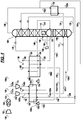
- FIGS. 1 , 2A-C , 3A-D , and 4 illustrate various embodiments of the present process and apparatus for separation of a compressed feed air stream 105 to produce an oxygen product 170, and an optional nitrogen product 180.
- the figures illustrate both required and optional features of the present process and apparatus.
- the compressed feed air stream 105 may be formed by compressing air 100 in a main air compressor 102 and removing impurities, such as CO 2 and H 2 O from the air in adsorption unit 104.
- the compressed feed air stream 105 is divided into two or more portions.
- a first portion 107a may be compressed in one or more booster compressors 110 and the compressed first portion 107b passed into a first (warmer) end of a first heat exchanger section 184.
- the first portion 107b is cooled in the first heat exchanger section 184, and subsequently withdrawn from a second (colder) end of the first heat exchanger section 184.
- the compressed first portion 107b may be at least partially condensed in the first heat exchanger section 184.
- the thermodynamic state of the fluid (107c) leaving the second (colder) end of heat exchanger section 184 is generally all liquid for any pressure below the critical pressure of air.
- the temperature is generally as cold or colder than the critical temperature (approximately -140°C) and preferably below -160°C.
- the first heat exchanger section 184 may be part or all of a so-called higher-pressure heat exchanger.
- the higher-pressure heat exchanger may be a so-called plate-fin heat exchanger or any other type of suitable heat exchanger known in the art.
- the first portion 107c withdrawn from the second (colder) end of the first heat exchanger section 184 is passed to a multi-column separation system comprising a lower-pressure column 188 and a higher-pressure column 190.
- the first portion 107c may be passed to the higher-pressure column 190 and/or the lower-pressure column of the multi-column separation system.
- the first portion 107c may be a liquid stream, a supercritical dense fluid, or a partially condensed stream. In FIGS. 1 , 2A-C , 3A-D , and 4 , the first portion 107c is passed to the higher-pressure column 190.
- the first portion 107c withdrawn from the second (colder) end of the heat exchanger 184 may be expanded prior to being passed to the higher-pressure column 190 and/or the lower-pressure column 188.
- the first portion 107c of the compressed feed air stream 105 may be expanded in a valve 112, dense fluid expander, or other device known in the art to expand a fluid.
- the first portion 107c may be introduced into the higher-pressure column 190 and/or the lower-pressure column 188 as a predominantly liquid air feed.
- the first portion 107c may be cooled in first subcooler heat exchange section 192, supplementing or replacing stream 124.
- the first portion 107c may be cooled in the second subcooler heat exchange section 194.
- a second portion 108a of the compressed feed air stream 105 is passed into a first (warmer) end of a second heat exchanger section 186.
- the pressure of the second portion 108a of the compressed feed air stream 105 may be less than the pressure of the first portion 107b of the compressed feed air stream (105).
- the second portion 108a is cooled in the second heat exchanger section 186, and subsequently withdrawn from a second (colder) end of the second heat exchanger section 186.
- the thermodynamic state of the fluid leaving the second (colder) end of the second heat exchanger section 186 is generally subcritical pressure, typically 4 to 10 atmospheres pressure, and generally no more than 10 mole% liquid, and preferably no more than 3 mole% liquid.
- the second heat exchanger section 186 may be part or all of a so-called lower-pressure core heat exchanger.
- the lower-pressure core heat exchanger may be a so-called plate-fin heat exchanger or any other type of heat exchanger known in the art.
- the lower-pressure heat exchanger may have a lower operating pressure rating than the higher-pressure heat exchanger.
- the lower-pressure heat exchanger may be a lower cost unit than the higher-pressure heat exchanger.
- Capital cost savings for the heat exchanger system can be achieved for heat exchanger systems using a higher-pressure heat exchanger and a lower-pressure heat exchanger as compared to a heat exchanger system where all of the heat exchangers are rated for higher pressure operation.
- the first heat exchanger section 184 and the second heat exchanger section 186 are part of physically and thermodynamically separate heat exchangers.
- a first heat exchanger comprises first exchanger section 184 and the second heat exchanger comprises the second heat exchanger section 186.
- the first heat exchanger may be rated for higher pressures than the second heat exchanger. Though it is obvious to one of ordinary skill in the art, the first heat exchanger section is also physically and thermodynamically separate from the second heat exchanger section.
- the second portion 108b withdrawn from the second (colder) end of the second heat exchanger section 186 is passed to the higher-pressure column 190 of the multi-column separation system.
- a third portion 109a of the compressed feed air stream 105 may be compressed in one or more booster compressors 114 and passed into the first (warmer) end of the first heat exchanger section 184.
- the third portion 109b may be cooled in the first heat exchanger section 184, and subsequently withdrawn from a position intermediate the first (warmer) end and the second (colder) end of the first heat exchanger section 184.
- booster compressor 110 and booster compressor 114 are shown as separate machines in FIGS. 1 , 2A , 2B , 2C , and 4 , the two booster compressors can be a single machine. Both the high pressure air stream 107b and the medium pressure air stream 109b may be at the same pressure and come from the final stage discharge of the single booster compressor. Alternatively, stream 109b may be discharged from an intermediate stage of a single multi-stage booster compressor and stream 107b from the final stage of the single multi-stage booster compressor.
- the booster compressors may be driven by one or both of expander 132 or expander 116.
- the third portion 109c withdrawn from the position intermediate the first (warmer) end and the second (colder) end of the first heat exchanger section 184 may be expanded in an expander 116 where it is further cooled, while producing work.
- the third portion 109d after expanding may be passed to the higher-pressure column 190 and/or the lower-pressure column 188.
- Expander 116 may be a dissipative, generator-loaded, or process-loaded expander.
- the third portion 109d after expanding and the second portion 108b may be blended prior to being passed to the higher-pressure column 190.
- the combined stream comprising the second portion 108b and third portion 109d may be introduced as a predominantly vapor feed air into the higher-pressure column 190 at an elevation in the higher-pressure column 190 below that of the first portion 107c of the compressed feed air stream 105.
- an oxygen-enriched fraction 122 is withdrawn as a liquid from the bottom section of the higher-pressure column 190 and passed to a lower-pressure column 188 of the multi-column separation system.
- the oxygen-enriched fraction 122 may be introduced into a middle section of the lower-pressure column 188.
- the higher-pressure column 190 and the lower-pressure column 188 are each distillation-type columns. They can be constructed of systems and materials that are well known in the art (for example: sieve trays, bubble-cap trays, valve trays, random packing, structured packing).
- the higher-pressure column 190 is so-called "higher-pressure” because it has an operating pressure higher than the lower-pressure column 188.
- the lower-pressure column 188 is so-called "lower-pressure” because it has an operating pressure lower than the higher-pressure column 190.
- the multi-column separation system may also include one or more additional columns for producing an argon byproduct. At least one additional column may be a standalone column, or part of the lower pressure column 188 where a physical barrier is installed in the lower-pressure column to separate the sections in the lower pressure column.
- an oxygen-rich fraction 166 is withdrawn from a bottom section of the lower pressure column 188.
- the oxygen-rich fraction 166 is passed to the second (colder) end of the first heat exchanger section 184, heated in the first heat exchanger section 184, and subsequently withdrawn from the first (warmer) end of the first heat exchanger section 184 as oxygen product 170.
- the pressure of the oxygen-rich fraction 166 withdrawn from the lower pressure column 188 may be increased by passing the oxygen-rich fraction 166 through pump 168.
- the oxygen-rich fraction 166 may be a liquid stream or a supercritical dense fluid.
- a nitrogen-enriched fraction 128a is withdrawn from the higher-pressure column 190.
- the nitrogen-enriched fraction 128a may be withdrawn from the higher-pressure column 190 at an elevation below the elevation that the nitrogen-rich fraction 127 is withdrawn.
- the nitrogen-enriched fraction 128a may be withdrawn from the same location as nitrogen-rich fraction 127 and have the same composition as nitrogen-rich fraction 127.
- the nitrogen-enriched fraction 128a withdrawn from the higher-pressure column 190 is passed to the second (colder) end of the first heat exchanger section 184, heated in the first heat exchanger section 184, and withdrawn from a position intermediate the first (warmer) end and the second (colder) end of the first heat exchanger section 184.
- the nitrogen-enriched fraction 128b withdrawn from the position intermediate the first (warmer) end and the second (colder) end of the first heat exchanger section 184 is expanded in an expander 132 to produce work and reduce the pressure of the nitrogen-enriched fraction 128b.
- Expander 132 may be a dissipative, generator-loaded, or process-loaded expander.
- At least a first portion 128e of the expanded nitrogen-enriched fraction 128c is passed to the second (colder) end of the second heat exchanger section 186, heated in the second heat exchanger section 186, and withdrawn from the first (warmer) end of the second heat exchanger section 186.
- all of the expanded nitrogen-enriched fraction 128c is passed to the second (colder) end of the second heat exchanger section 186.
- FIGS. 1 , 2A , 2B , and 3A-D all of the expanded nitrogen-enriched fraction 128c is passed to the second (colder) end of the second heat exchanger section 186.
- the nitrogen-enriched fraction 128c is blended with another stream 152b, described below, and a first portion 128e of the expanded nitrogen-enriched fraction 128c (as part of the blend) is passed to the second (colder) end of the second heat exchanger section 186 and a second portion 128d of the expanded nitrogen-enriched fraction 128c (as part of the blend) is passed to the second (colder) end of the first heat exchanger section 184.
- a first portion 128e of the expanded nitrogen-enriched fraction 128c is passed to the second (colder) end of the second heat exchanger section 186, heated in the second heat exchanger section 186, and withdrawn from the first (warmer) end of the second heat exchanger section 186 as part of waste stream 260.
- a second portion 128d of the expanded nitrogen-enriched fraction 128c is passed to the second (colder) end of the first heat exchanger section 184, heated in the first heat exchanger section 184, and withdrawn from the first (warmer) end of the first heat exchanger section 184 as a part of waste stream 162.
- a nitrogen-rich byproduct 150 may be withdrawn from the upper region of the lower-pressure column 188.
- the nitrogen-rich byproduct 150 may be divided into a first fraction 152a and a second fraction 151a.
- the upper region is defined as section bound by a point where nitrogen-enriched intermediate stream 124 enters the lower-pressure column and the lower-pressure column top end. Typically, the top end is the location where stream 148 enters the lower-pressure column.
- the first fraction 152a of the nitrogen-rich byproduct 150 may be passed to a first (colder) end of a first subcooler heat exchanger section 192, heated in the first subcooler heat exchanger section 192, and withdrawn from a second (warmer) end of the first subcooler heat exchanger section 192.
- the at least a portion of the first fraction 152b of the nitrogen-rich byproduct 150 is passed from the second (warmer) end of the first subcooler heat exchanger section 192 to the second (colder) end of the first heat exchanger section 184, heated in the first heat exchanger section 184, and withdrawn from the first (warmer) end of the first heat exchanger section 184 as a first nitrogen-rich discharge byproduct gas 162.
- a second portion 152d of the first fraction 152b of the nitrogen-rich byproduct 150 is passed from the second (warmer) end of the first subcooler heat exchanger section 192 to the second (colder) end of the second heat exchanger section 186, heated in the second heat exchanger section 186, and withdrawn from the first (warmer) end of the second heat exchanger section 186 as a third nitrogen-rich discharge product gas 260.
- the second portion 152d of the first fraction 152b of the nitrogen-rich byproduct 150 is blended with the expanded nitrogen-enriched fraction 128c from the expander 132 and passed together through the second (colder) end of the second heat exchanger section 186.
- the first fraction 152b of the nitrogen-rich byproduct 150 from the second (warmer) end of the first subcooler heat exchanger section 192 is blended with the nitrogen-enriched fraction 128c from the expander 132 to form a nitrogen-rich mixture 258.
- a first portion 259 of the nitrogen-rich mixture 258 is passed to the second (colder) end of the first heat exchanger section 184, heated in the first heat exchanger section 184, and withdrawn from the first (warmer) end of the first heat exchanger section 184 as a first nitrogen-rich discharge gas 162.
- a second portion 256 of the nitrogen-rich mixture 258 is passed to the second (colder) end of the second heat exchanger section 186, heated in the second heat exchanger section 186, and withdrawn from the first (warmer) end of the second heat exchanger section 186 as a third nitrogen-rich discharge gas 260.
- the advantage of blending the first fraction 152b of the nitrogen-rich byproduct 150 with the nitrogen-enriched fraction 128c from the expander 132 is to provide the greatest flexibility to control the flow split of streams 128c and 152b between the first heat exchanger section 184 and the second heat exchanger section 186. This flexibility will lead to the most efficient operation.
- the second fraction 151a of the nitrogen-rich byproduct 150 may be passed to a first (colder) end of a second subcooler heat exchanger section 194, heated in the second subcooler heat exchanger section 194, and withdrawn from a second (warmer) end of the second subcooler heat exchanger section 194.
- the second fraction 151b of the nitrogen-rich byproduct 150 may be passed from the second (warmer) end of the second subcooler heat exchanger section 194 to the second (colder) end of the second heat exchanger section 186, heated in the second heat exchanger section 186, and withdrawn from the first (warmer) end of the second heat exchanger section 186 as a second nitrogen-rich discharge byproduct gas 158.
- a low pressure nitrogen product can be produced by withdrawing a nitrogen-rich gas stream (not shown) from the top end of upper region of the lower-pressure column 188, optionally heating this nitrogen-rich gas stream in the first subcooler heat exchanger section 192 and/or second subcooler heat exchanger section194, or a third subcooler heat exchanger, and subsequently heating the nitrogen-rich gas stream further in the first heat exchanger section 184 and/or the second heat exchanger section 186.
- the nitrogen-rich byproduct 150 may be removed from the lower-pressure column 188 as a vapor-side draw from a location in the upper region below where the nitrogen-rich gas stream is withdrawn. If the flow rate of the nitrogen-rich gas stream is of sufficient magnitude, one of the first fraction 152a of the nitrogen-rich byproduct 150 and the second fraction 151a of the nitrogen-rich byproduct 150 may be eliminated and replaced with this nitrogen-rich gas stream.
- a nitrogen-rich fraction 127 may be withdrawn from the top end of the higher-pressure column 190.
- a second portion 129 of the nitrogen-rich fraction 127 may be passed to the second (colder) end of the second heat exchanger section 186, heated in the second heat exchanger section 186, and subsequently withdrawn from the first (warmer) end of the second heat exchanger section 186 as a gaseous nitrogen product 180.
- second portion 129 may be heated in the second heat exchanger section 186.
- gaseous nitrogen product 180 using an alternate technique called pumped-LIN.
- an additional liquid is withdrawn from stream 144, optionally pumped to a pressure greater than that of the higher-pressure column 190 and may be subsequently passed to the second (colder) end of the first heat exchanger section 184, heated in the first heat exchanger section 184, and subsequently withdrawn from the first (warmer) end of the first heat exchanger section 184 as a gaseous nitrogen product 180.
- the nitrogen-rich fraction 127 or a first portion 140 of the nitrogen-rich fraction 127 withdrawn from the top end of the higher-pressure column 190 may be passed to a reboiler-condenser 142 of the multi-column distillation system.
- the nitrogen-rich fraction 127 or a first portion 140 of the nitrogen-rich fraction 127 may be condensed in the reboiler-condenser 142, and withdrawn from the reboiler-condenser 142 as nitrogen-rich liquid 144.
- the reboiler-condenser 142 thermally couples the lower-pressure column 188 and the higher-pressure column 190.
- a large part (greater than 40 mole%) of the nitrogen-rich liquid (144) is returned to the top of the higher-pressure column 190 as reflux.
- a part 146 of the nitrogen-rich liquid 144 may be passed to a second (warmer) end of the second subcooler heat exchanger section 194, cooled in the second subcooler heat exchanger section 194, and withdrawn from the first (colder) end of the second subcooler heat exchanger section 194.
- the part 146 of the nitrogen-rich liquid 144 withdrawn from the first (colder) end of the second subcooler heat exchanger section 194 may be passed to the top end of the lower-pressure column 188 as reflux.
- a part 146 of the nitrogen-rich liquid 144 may be passed to a second (warmer) end of the first subcooler heat exchanger section 192, cooled in the first subcooler heat exchanger section 192, and withdrawn from the first (colder) end of the first subcooler heat exchanger section 192.
- stream 146 which is passed through the second subcooler heat exchanger section 194 being formed from the stream withdrawn from the reboiler-condenser
- this stream may alternatively be taken from an intermediate location in the higher-pressure column.
- stream 146 may be taken as a liquid draw from the location of stream 128a off-take. In such an event, all of the nitrogen-rich liquid 144 is returned to the top of the higher-pressure column 190 as reflux.
- a nitrogen-enriched intermediate 124 may be withdrawn from the higher-pressure column 190 from an elevation in the higher-pressure column which is above that of the predominantly liquid air feed.
- the nitrogen-enriched intermediate 124 may be passed to the second (warmer) end of the first subcooler heat exchanger section 192, cooled in the first subcooler heat exchanger section 192, withdrawn from the first (colder) end of the first subcooler heat exchanger section 192, and passed to an intermediate section of the lower-pressure column 188.
- the nitrogen-enriched intermediate 124 may be passed to the second (warmer) end of the second subcooler heat exchanger section 194, cooled in the second subcooler heat exchanger section 194, withdrawn from the first (colder) end of the second subcooler heat exchanger section 194, and passed to an intermediate section of the lower-pressure column 188.
- the first subcooler heat exchanger section 192 may be structurally integrated with the first heat exchanger section 184.
- the second subcooler heat exchanger section 194 may be structurally integrated with the second heat exchanger section 186.
- FIG. 3A illustrates the same heat exchanger subprocess of FIG. 2A where the subcooler heat exchanger sections 192 and 194 are separate from the heat exchanger sections 184 and 186.
- the second subcooler heat exchanger section 194 is integrated with the second heat exchanger section 186 as a single heat exchanger 386.
- the horizontal dotted line shown in the heat exchanger 386 represents the boundary, or interface, between the second subcooler heat exchanger section 194 and the second heat exchanger section 186.
- the part 146 of the nitrogen-rich liquid fraction 144 is passed to the second (warmer) end of the second subcooler heat exchanger section 194 of the heat exchanger 386, bypassing the second heat exchanger section 186, and is withdrawn from the first (colder) end of the second subcooler heat exchanger section 194 of the heat exchanger 386.
- the second fraction 151a of the nitrogen-rich byproduct 150 is passed to the first (colder) end of the second subcooler heat exchanger section 194 of the heat exchanger 386 and is withdrawn from the first (warmer) end of the second heat exchanger section 186 of the heat exchanger 386.
- the expanded nitrogen-enriched fraction 128c, the second portion 152d of the first fraction 152a of the nitrogen-rich byproduct 150, and the second portion 129 of the nitrogen-rich fraction 127 are each passed to the second (colder) end of the second heat exchanger section 186 of the heat exchanger 386, bypassing the second subcooler heat exchanger section 194, and withdrawn from the first (warmer) end of the second heat exchanger section 186 of the heat exchanger 386.
- the second portion 108b of the compressed feed air stream is passed to the first (warmer) end of the second heat exchanger section 186 and is withdrawn from the second (colder) end of the second heat exchanger section 186 of the heat exchanger 386 bypassing the second subcooler heat exchanger section 194 of the heat exchanger 386.
- This type of heat exchanger arrangement is commonly used to reduce capital costs.
- the heat transfer efficiency of the heat exchanger arrangement shown in FIG. 3B for the second subcooler heat exchanger section 194 and second heat exchanger section 186 is essentially equivalent to the heat exchanger arrangement shown in FIG. 3A .
- the first subcooler heat exchanger section 192 is integrated with the first heat exchanger section 184 as a single heat exchanger 384.
- the horizontal dotted line shown in the heat exchanger 384 represents the boundary between the first subcooler heat exchanger section 192 and the first heat exchanger section 184.
- the dotted line represents the interface between the second (warmer) end of the first subcooler heat exchanger section 192 and the second (colder) end of the first heat exchanger section 184.
- the first fraction 152a of the nitrogen-rich byproduct 150 is passed to the first (colder) end of the first subcooler heat exchanger section 192 of the heat exchanger 384.
- a first portion 152c of the first fraction 152b of the nitrogen-rich byproduct 150 passes from the second (warmer) end of the first subcooler heat exchanger section 192 of the heat exchanger 384 to the second (colder) end of the first heat exchanger section 184 and is withdrawn from the first (warmer) end of the first heat exchanger section 184 of the heat exchanger 384 as the first nitrogen-rich discharge byproduct gas 162.
- a second portion 152d of the first fraction 152b of the nitrogen-rich byproduct 150 is withdrawn from the second (warmer) end of the first subcooler heat exchanger section 184 of the heat exchanger 384 bypassing the first heat exchanger section 184.
- the nitrogen-enriched fraction 128c and the oxygen-rich fraction 166 are each passed to the second (colder) end of the first heat exchanger section 184 of the heat exchanger 384, bypassing the first subcooler heat exchanger section 192, and withdrawn from the first (warmer) end of the first heat exchanger section 184 of the heat exchanger 384.
- This type of heat exchanger arrangement is commonly used to reduce capital costs.
- the heat transfer efficiency of the heat exchanger arrangement shown in FIG. 3C for the first subcooler heat exchanger section 192 and first heat exchanger section 184 is essentially equivalent to the heat exchanger arrangement shown in FIG. 3A .
- first subcooler heat exchanger section 192 is integrated with the first heat exchanger section 184 as a single heat exchanger 384 and the second subcooler heat exchanger section 194 is integrated with the second heat exchanger section 186 as a single heat exchanger 386.
- the description for the integrated heat exchanger 384 for FIG. 3C and the description for the integrated heat exchanger 386 for FIG. 3B applies to the integrated heat exchangers 384 and 386.
- the heat transfer efficiency of the heat exchanger arrangement shown in FIG. 3D for the integrated heat exchangers 384 and 386 are essentially equivalent to the heat exchanger arrangement shown in FIG. 3A for separated heat exchangers.
- the integrated heat exchanger 386 in FIG. 3B is applied to the process flow diagram of FIG. 2C .
- the apparatus comprises a multi-column distillation system comprising a lower-pressure column 188 and a higher-pressure column 190, a first heat exchanger, a second heat exchanger, and an expander 132.
- the first heat exchanger comprises a first heat exchanger section 184.
- the first heat exchanger section 184 has a first (warmer) end and a second (colder) end.
- the first (warmer) end is operatively disposed to receive a first portion 107b of the compressed feed air stream 105.
- the apparatus may comprise a booster compressor 110 and the first (warmer) end may be operatively disposed to receive the first portion 107b from a booster compressor 110.
- At least one of the lower-pressure column 188 or the higher-pressure column 190 is operatively disposed to receive the first portion 107c of the compressed feed air stream 105 from the second (colder) end of the first heat exchanger section 184.
- the second (colder) end of the first heat exchanger section 184 is operatively disposed to receive an oxygen-rich fraction 166 from the lower-pressure column 188 and the first (warmer) end of the first heat exchanger section 184 is operatively disposed to discharge the oxygen product 170.
- the second (colder) end of the first heat exchanger section 184 is operatively disposed to receive a nitrogen-enriched fraction 128a from the higher-pressure column 190.
- the second heat exchanger comprises a second heat exchanger section 186.
- the second heat exchanger may have a lower operating pressure rating than the first heat exchanger.
- the second heat exchanger section 186 has a first (warmer) end and a second (colder) end.
- the first (warmer) end is operatively disposed to receive a second portion 108a of the compressed feed air stream 105.
- the pressure of the second portion 108a of the compressed feed air stream 105 may be less than the pressure of the first portion 107b of the compressed feed air stream 105.
- the higher-pressure column 190 is operatively disposed to receive the second portion 108b of the compressed feed air stream 105 from the second (colder) end of the second heat exchanger section 186.
- the expander 132 has an inlet and an outlet.
- the inlet of the expander 132 is operatively disposed to receive the nitrogen-enriched fraction 128b withdrawn from a position intermediate the first (warmer) end and the second (colder) end of the first heat exchanger section 184.
- the second (colder) end of the second heat exchanger section 186 may be operatively disposed to receive the at least a portion of the nitrogen-enriched fraction 128c from the outlet of the expander 132.
- the second (colder) end of the second heat exchanger section 186 may be operatively disposed to receive a first portion 128e of the expanded nitrogen-enriched fraction 128c from the outlet of the expander 132, and the second (colder) end of the first heat exchanger section 184 may be operatively disposed to receive a second portion 128d of the nitrogen-enriched fraction 128c from the outlet of the expander 132.
- the apparatus may further comprise a second expander 116 having an inlet and an outlet.
- the first (warmer) end of the first heat exchanger section 184 may be operatively disposed to receive a third portion 109b of the compressed feed air stream 105 and discharge the third portion 109c from a position intermediate the first (warmer) end and the second (colder) end of the first heat exchanger section 184.
- the inlet of the second expander 116 may be operatively disposed to receive the third portion 109c withdrawn from the position intermediate the first (warmer) end and the second (colder) end of the first heat exchanger section 184.
- At least one of the higher-pressure column 190 or the lower-pressure column 188 may be operatively disposed to receive the third portion 109d from the outlet of the second expander 116.
- the apparatus may further comprise a first subcooler heat exchanger section 192 and a second subcooler heat exchanger section 194.
- the first subcooler heat exchanger section 192 has a first (colder) end and a second (warmer) end.
- the first (colder) end of the first subcooler heat exchanger section 192 may be operatively disposed to receive a first fraction 152a of a nitrogen-rich byproduct 150 from the upper region of the lower-pressure column and discharge the first fraction 152b from the second (warmer) end of the first subcooler heat exchanger section 192.
- the second (colder) end of the first heat exchanger section 184 may be operatively disposed to receive the at least a portion of first fraction 152b from the second (warmer) end of the first subcooler heat exchanger section 192.
- the second subcooler heat exchanger section 194 has a first (colder) end and a second (warmer) end.
- the first (colder) end of the second subcooler heat exchanger section 194 may be operatively disposed to receive a second fraction 151a of the nitrogen-rich byproduct 150 and discharge the second fraction 151b from the second (warmer) end of the second subcooler heat exchanger section 194.
- the second (colder) end of the second heat exchanger section 186 may be operatively disposed to receive at the second fraction 151b from the second (warmer) end of the second subcooler heat exchanger section 194.
- the second (colder) end of the second heat exchanger section 186 may be operatively disposed to receive a second portion 152d of the first fraction 152b from the second (warmer) end of the first subcooler heat exchanger section 192 and the second (colder) end of the first heat exchanger section 184 may be operatively disposed to receive a first portion 152c of the first fraction 152b from the second (warmer) end of the first subcooler heat exchanger section 192.
- Case 1 corresponds to the process shown in FIG. 5 , where the first and second heat exchanger sections are combined into one single heat exchanger section 584 and first and second subcooler heat exchanger sections are combined into one single subcooler heat exchanger section 596.
- Reference numbers for streams in FIG. 5 in common with the earlier figures have the same reference number as in the earlier figures.
- Case 4 The results shown in the 4 th column, Case 4, are for a comparative case shown in FIG. 7 .
- the results show the modest effect of only splitting stream 258 between the two heat exchangers.
- Case 4 can be envisioned as the embodiment of FIG. 4 except expander 132 draws its flow from the second heat exchanger section 186, as in the prior art case.
- the power is reduced by 120 kW compared to Case 2 (Prior Art).
- FIG. 4 Power kW 56,417 57,563 57,175 57,443 56,882 Penalty compared to Case 1 kW - 1,146 758 1,026 405 Improvement compared to Case 2 kW 1,146 - 388 120 741 Dry Air flow (105) Nm 3 /hr 483,477 481,731 482,950 482,137 483,705 MP Air flow (108a) Nm 3 /hr 309,030 278,692 292,946 280,165 295,738 MP Air pressure (108a) bara 5.6 5.6 5.6 5.5 JT Air flow Nm 3 /hr 135,003 114,274 129,088 114,571 127,441 JT Air pressure (107b) bara 75 75 75 75 75 75 Air Expander flow (109b) Nm 3 /hr 39,444 88,764 60,916 87,401 60,526 Air
Landscapes
- Engineering & Computer Science (AREA)
- Physics & Mathematics (AREA)
- Mechanical Engineering (AREA)
- Thermal Sciences (AREA)
- General Engineering & Computer Science (AREA)
- Health & Medical Sciences (AREA)
- Emergency Medicine (AREA)
- Separation By Low-Temperature Treatments (AREA)
Applications Claiming Priority (1)
| Application Number | Priority Date | Filing Date | Title |
|---|---|---|---|
| US15/993,993 US11054182B2 (en) | 2018-05-31 | 2018-05-31 | Process and apparatus for separating air using a split heat exchanger |
Publications (3)
| Publication Number | Publication Date |
|---|---|
| EP3575717A2 true EP3575717A2 (fr) | 2019-12-04 |
| EP3575717A3 EP3575717A3 (fr) | 2020-03-11 |
| EP3575717B1 EP3575717B1 (fr) | 2024-03-06 |
Family
ID=66676438
Family Applications (1)
| Application Number | Title | Priority Date | Filing Date |
|---|---|---|---|
| EP19177393.6A Active EP3575717B1 (fr) | 2018-05-31 | 2019-05-29 | Procédé et dispositif de séparation d'air avec un échangeur de chaleur principal divisé |
Country Status (3)
| Country | Link |
|---|---|
| US (1) | US11054182B2 (fr) |
| EP (1) | EP3575717B1 (fr) |
| CN (2) | CN110553466B (fr) |
Families Citing this family (4)
| Publication number | Priority date | Publication date | Assignee | Title |
|---|---|---|---|---|
| US10746461B2 (en) * | 2016-08-30 | 2020-08-18 | 8 Rivers Capital, Llc | Cryogenic air separation method for producing oxygen at high pressures |
| US11054182B2 (en) * | 2018-05-31 | 2021-07-06 | Air Products And Chemicals, Inc. | Process and apparatus for separating air using a split heat exchanger |
| US11029087B2 (en) * | 2018-11-16 | 2021-06-08 | L'air Liquide Societe Anonyme Pour L'etude Et L'exploitation Des Procedes Georges Claude | Method for utilizing waste air to improve the capacity of an existing air separation unit |
| US11512897B2 (en) * | 2021-01-14 | 2022-11-29 | Air Products And Chemicals, Inc. | Fluid recovery process and apparatus |
Citations (3)
| Publication number | Priority date | Publication date | Assignee | Title |
|---|---|---|---|---|
| US4555256A (en) | 1982-05-03 | 1985-11-26 | Linde Aktiengesellschaft | Process and device for the production of gaseous oxygen at elevated pressure |
| FR2778971A1 (fr) | 1998-05-20 | 1999-11-26 | Air Liquide | Installation de production d'un gaz, forme d'un constituant ou d'un melange de constituants de l'air sous une haute pression |
| EP2824407A1 (fr) | 2013-07-11 | 2015-01-14 | Linde Aktiengesellschaft | Procédé de génération d'au moins un produit de l'air, installation de décomposition de l'air, procédé et dispositif de production d'énergie électrique |
Family Cites Families (22)
| Publication number | Priority date | Publication date | Assignee | Title |
|---|---|---|---|---|
| US3086371A (en) | 1957-09-12 | 1963-04-23 | Air Prod & Chem | Fractionation of gaseous mixtures |
| GB1117561A (en) | 1963-12-24 | 1968-06-19 | Air Prod Ltd | Improvements in or relating to processes and plant for the fractionation of air |
| DE2557453C2 (de) * | 1975-12-19 | 1982-08-12 | Linde Ag, 6200 Wiesbaden | Verfahren zur Gewinnung von gasförmigem Sauerstoff |
| GB2057660B (en) * | 1979-05-17 | 1983-03-16 | Union Carbide Corp | Process and apparatus for producing low purity oxygen |
| US4400188A (en) | 1981-10-27 | 1983-08-23 | Air Products And Chemicals, Inc. | Nitrogen generator cycle |
| GB8921428D0 (en) * | 1989-09-22 | 1989-11-08 | Boc Group Plc | Separation of air |
| US5341646A (en) * | 1993-07-15 | 1994-08-30 | Air Products And Chemicals, Inc. | Triple column distillation system for oxygen and pressurized nitrogen production |
| US5355682A (en) | 1993-09-15 | 1994-10-18 | Air Products And Chemicals, Inc. | Cryogenic air separation process producing elevated pressure nitrogen by pumped liquid nitrogen |
| FR2711778B1 (fr) | 1993-10-26 | 1995-12-08 | Air Liquide | Procédé et installation de production d'oxygène et/ou d'azote sous pression. |
| US5956974A (en) * | 1998-01-22 | 1999-09-28 | Air Products And Chemicals, Inc. | Multiple expander process to produce oxygen |
| US5934104A (en) * | 1998-06-02 | 1999-08-10 | Air Products And Chemicals, Inc. | Multiple column nitrogen generators with oxygen coproduction |
| US6233970B1 (en) | 1999-11-09 | 2001-05-22 | Air Products And Chemicals, Inc. | Process for delivery of oxygen at a variable rate |
| US6962062B2 (en) | 2003-12-10 | 2005-11-08 | L'Air Liquide, Société Anonyme à Directoire et Conseil de Surveillance pour l'Etude et l'Exploitation des Proédés Georges Claude | Process and apparatus for the separation of air by cryogenic distillation |
| EP1767884A1 (fr) | 2005-09-23 | 2007-03-28 | L'Air Liquide Société Anon. à Directoire et Conseil de Surveillance pour l'Etude et l'Exploitation des Procédés Georges Claude | Procédé et dispositif pour la séparation cryogénique d'air |
| WO2007057730A1 (fr) | 2005-11-17 | 2007-05-24 | L'air Liquide, Societe Anonyme Pour L'etude Et L'exploitation Des Procedes Georges Claude | Procede et appareil de separation d'air par distillation cryogenique |
| EP2313724A2 (fr) | 2008-08-14 | 2011-04-27 | Linde Aktiengesellschaft | Procédé et dispositif de séparation de l'air à basse température |
| FR3010778B1 (fr) | 2013-09-17 | 2019-05-24 | Air Liquide | Procede et appareil de production d'oxygene gazeux par distillation cryogenique de l'air |
| JP6209476B2 (ja) | 2014-03-27 | 2017-10-04 | 株式会社ショーワ | センサユニット、トルク検出装置及び電動パワーステアリング装置 |
| EP3196574B1 (fr) * | 2016-01-21 | 2021-05-05 | Linde GmbH | Procédé et appareil de production d'azote gazeux sous pression par séparation cryogénique d'air |
| CN106949708B (zh) * | 2016-11-25 | 2020-02-11 | 乔治洛德方法研究和开发液化空气有限公司 | 一种对原有低温空分装置进行改装用以提高低压纯氮气产量的方法 |
| CN207365553U (zh) * | 2017-10-18 | 2018-05-15 | 上海宝钢气体有限公司 | 一种生产高纯氧和高纯氮的装置 |
| US11054182B2 (en) * | 2018-05-31 | 2021-07-06 | Air Products And Chemicals, Inc. | Process and apparatus for separating air using a split heat exchanger |
-
2018
- 2018-05-31 US US15/993,993 patent/US11054182B2/en active Active
-
2019
- 2019-05-29 EP EP19177393.6A patent/EP3575717B1/fr active Active
- 2019-05-30 CN CN201910462120.6A patent/CN110553466B/zh active Active
- 2019-05-30 CN CN201920800096.8U patent/CN210980535U/zh active Active
Patent Citations (3)
| Publication number | Priority date | Publication date | Assignee | Title |
|---|---|---|---|---|
| US4555256A (en) | 1982-05-03 | 1985-11-26 | Linde Aktiengesellschaft | Process and device for the production of gaseous oxygen at elevated pressure |
| FR2778971A1 (fr) | 1998-05-20 | 1999-11-26 | Air Liquide | Installation de production d'un gaz, forme d'un constituant ou d'un melange de constituants de l'air sous une haute pression |
| EP2824407A1 (fr) | 2013-07-11 | 2015-01-14 | Linde Aktiengesellschaft | Procédé de génération d'au moins un produit de l'air, installation de décomposition de l'air, procédé et dispositif de production d'énergie électrique |
Also Published As
| Publication number | Publication date |
|---|---|
| EP3575717A3 (fr) | 2020-03-11 |
| US11054182B2 (en) | 2021-07-06 |
| EP3575717B1 (fr) | 2024-03-06 |
| US20190368811A1 (en) | 2019-12-05 |
| CN110553466A (zh) | 2019-12-10 |
| CN210980535U (zh) | 2020-07-10 |
| CN110553466B (zh) | 2021-08-06 |
Similar Documents
| Publication | Publication Date | Title |
|---|---|---|
| EP3575717B1 (fr) | Procédé et dispositif de séparation d'air avec un échangeur de chaleur principal divisé | |
| KR101275364B1 (ko) | 초저온 공기 분리 시스템 | |
| US6662595B2 (en) | Process and device for obtaining a compressed product by low temperature separation of air | |
| KR100343276B1 (ko) | 가온된터빈재순환에의한극저온공기분리방법 | |
| TW542895B (en) | Obtaining argon using a three-column system for the fractionation of air and a crude argon column | |
| EP0644388A1 (fr) | Séparation cryogénique d'air | |
| JP2836781B2 (ja) | 空気分離方法 | |
| AU2010329766B2 (en) | Process and unit for the separation of air by cryogenic distillation | |
| US9360250B2 (en) | Process and apparatus for the separation of air by cryogenic distillation | |
| JPH0626759A (ja) | 空気分離方法 | |
| US20090071191A1 (en) | Cryogenic air separation process with excess turbine refrigeration | |
| JPH04227456A (ja) | 生成物ガスを生成するための極低温蒸留による空気分離方法及びそのための装置 | |
| US20060075779A1 (en) | Process for the cryogenic distillation of air | |
| CA3004415C (fr) | Procede et systeme d'apport de refrigeration supplementaire a une installation de separation d'air | |
| JP2002235982A (ja) | 三塔式空気低温精留システム | |
| US6718795B2 (en) | Systems and methods for production of high pressure oxygen | |
| US6305191B1 (en) | Separation of air | |
| US6397631B1 (en) | Air separation process | |
| JPH0682157A (ja) | 空気の分離 | |
| US20020053219A1 (en) | Method for plant and separating air by cryogenic distillation | |
| US6694776B1 (en) | Cryogenic air separation system for producing oxygen | |
| US20200080773A1 (en) | Cryogenic air separation unit with flexible liquid product make | |
| US5901577A (en) | Process and plant for air separation by cryogenic distillation | |
| US10995983B2 (en) | Method and apparatus for obtaining a compressed gas product by cryogenic separation of air | |
| US6192707B1 (en) | Cryogenic system for producing enriched air |
Legal Events
| Date | Code | Title | Description |
|---|---|---|---|
| PUAI | Public reference made under article 153(3) epc to a published international application that has entered the european phase |
Free format text: ORIGINAL CODE: 0009012 |
|
| STAA | Information on the status of an ep patent application or granted ep patent |
Free format text: STATUS: THE APPLICATION HAS BEEN PUBLISHED |
|
| AK | Designated contracting states |
Kind code of ref document: A2 Designated state(s): AL AT BE BG CH CY CZ DE DK EE ES FI FR GB GR HR HU IE IS IT LI LT LU LV MC MK MT NL NO PL PT RO RS SE SI SK SM TR |
|
| AX | Request for extension of the european patent |
Extension state: BA ME |
|
| PUAL | Search report despatched |
Free format text: ORIGINAL CODE: 0009013 |
|
| AK | Designated contracting states |
Kind code of ref document: A3 Designated state(s): AL AT BE BG CH CY CZ DE DK EE ES FI FR GB GR HR HU IE IS IT LI LT LU LV MC MK MT NL NO PL PT RO RS SE SI SK SM TR |
|
| AX | Request for extension of the european patent |
Extension state: BA ME |
|
| RIC1 | Information provided on ipc code assigned before grant |
Ipc: F25J 3/04 20060101AFI20200206BHEP |
|
| STAA | Information on the status of an ep patent application or granted ep patent |
Free format text: STATUS: REQUEST FOR EXAMINATION WAS MADE |
|
| 17P | Request for examination filed |
Effective date: 20200908 |
|
| RBV | Designated contracting states (corrected) |
Designated state(s): AL AT BE BG CH CY CZ DE DK EE ES FI FR GB GR HR HU IE IS IT LI LT LU LV MC MK MT NL NO PL PT RO RS SE SI SK SM TR |
|
| STAA | Information on the status of an ep patent application or granted ep patent |
Free format text: STATUS: EXAMINATION IS IN PROGRESS |
|
| 17Q | First examination report despatched |
Effective date: 20220330 |
|
| GRAP | Despatch of communication of intention to grant a patent |
Free format text: ORIGINAL CODE: EPIDOSNIGR1 |
|
| STAA | Information on the status of an ep patent application or granted ep patent |
Free format text: STATUS: GRANT OF PATENT IS INTENDED |
|
| INTG | Intention to grant announced |
Effective date: 20230928 |
|
| GRAS | Grant fee paid |
Free format text: ORIGINAL CODE: EPIDOSNIGR3 |
|
| GRAA | (expected) grant |
Free format text: ORIGINAL CODE: 0009210 |
|
| STAA | Information on the status of an ep patent application or granted ep patent |
Free format text: STATUS: THE PATENT HAS BEEN GRANTED |
|
| AK | Designated contracting states |
Kind code of ref document: B1 Designated state(s): AL AT BE BG CH CY CZ DE DK EE ES FI FR GB GR HR HU IE IS IT LI LT LU LV MC MK MT NL NO PL PT RO RS SE SI SK SM TR |
|
| P01 | Opt-out of the competence of the unified patent court (upc) registered |
Effective date: 20240131 |
|
| REG | Reference to a national code |
Ref country code: GB Ref legal event code: FG4D |
|
| REG | Reference to a national code |
Ref country code: NL Ref legal event code: FP |
|
| REG | Reference to a national code |
Ref country code: CH Ref legal event code: EP |
|
| REG | Reference to a national code |
Ref country code: IE Ref legal event code: FG4D |
|
| REG | Reference to a national code |
Ref country code: DE Ref legal event code: R096 Ref document number: 602019047629 Country of ref document: DE |
|
| PGFP | Annual fee paid to national office [announced via postgrant information from national office to epo] |
Ref country code: NL Payment date: 20240415 Year of fee payment: 6 |